EP0878237A2 - Base part for spray head, and spray head - Google Patents
Base part for spray head, and spray head Download PDFInfo
- Publication number
- EP0878237A2 EP0878237A2 EP98110812A EP98110812A EP0878237A2 EP 0878237 A2 EP0878237 A2 EP 0878237A2 EP 98110812 A EP98110812 A EP 98110812A EP 98110812 A EP98110812 A EP 98110812A EP 0878237 A2 EP0878237 A2 EP 0878237A2
- Authority
- EP
- European Patent Office
- Prior art keywords
- shower head
- water passage
- passage openings
- projection
- bottom part
- Prior art date
- Legal status (The legal status is an assumption and is not a legal conclusion. Google has not performed a legal analysis and makes no representation as to the accuracy of the status listed.)
- Granted
Links
Images

Classifications
-
- B—PERFORMING OPERATIONS; TRANSPORTING
- B05—SPRAYING OR ATOMISING IN GENERAL; APPLYING FLUENT MATERIALS TO SURFACES, IN GENERAL
- B05B—SPRAYING APPARATUS; ATOMISING APPARATUS; NOZZLES
- B05B1/00—Nozzles, spray heads or other outlets, with or without auxiliary devices such as valves, heating means
- B05B1/14—Nozzles, spray heads or other outlets, with or without auxiliary devices such as valves, heating means with multiple outlet openings; with strainers in or outside the outlet opening
- B05B1/18—Roses; Shower heads
- B05B1/185—Roses; Shower heads characterised by their outlet element; Mounting arrangements therefor
-
- B—PERFORMING OPERATIONS; TRANSPORTING
- B05—SPRAYING OR ATOMISING IN GENERAL; APPLYING FLUENT MATERIALS TO SURFACES, IN GENERAL
- B05B—SPRAYING APPARATUS; ATOMISING APPARATUS; NOZZLES
- B05B15/00—Details of spraying plant or spraying apparatus not otherwise provided for; Accessories
- B05B15/50—Arrangements for cleaning; Arrangements for preventing deposits, drying-out or blockage; Arrangements for detecting improper discharge caused by the presence of foreign matter
- B05B15/52—Arrangements for cleaning; Arrangements for preventing deposits, drying-out or blockage; Arrangements for detecting improper discharge caused by the presence of foreign matter for removal of clogging particles
- B05B15/528—Arrangements for cleaning; Arrangements for preventing deposits, drying-out or blockage; Arrangements for detecting improper discharge caused by the presence of foreign matter for removal of clogging particles by resilient deformation of the nozzle
-
- B—PERFORMING OPERATIONS; TRANSPORTING
- B05—SPRAYING OR ATOMISING IN GENERAL; APPLYING FLUENT MATERIALS TO SURFACES, IN GENERAL
- B05B—SPRAYING APPARATUS; ATOMISING APPARATUS; NOZZLES
- B05B15/00—Details of spraying plant or spraying apparatus not otherwise provided for; Accessories
- B05B15/60—Arrangements for mounting, supporting or holding spraying apparatus
- B05B15/62—Arrangements for supporting spraying apparatus, e.g. suction cups
Definitions
- the invention relates to a shower head with a water passage openings having bottom part made of an elastic material, the water passage openings Exit at the bottom of the shower head and over the bottom survive.
- shower heads can be found in almost every household as part of a shower head known for decades. Problems arise in particular with shower heads with hard to very hard tap water, from which very quickly and massively Eliminate limescale.
- the limescale deposits set the water passage openings and significantly impair the function of the shower head.
- EP-A-0 435 031 The principle known from EP-A-0 435 031 is based on a similar principle Shower head, at the bottom part of which there are hose-like outlet openings Material with a hardness of 20 to 100 shore are provided. By manual “rubbing" on the hose-like outlet openings should be in these deposited lime can be removed.
- the invention now goes a new way.
- shower head provided that the bottom part has an approximately ring-shaped Has projection that protrudes beyond the underside of the shower head and that the water passage openings along the length of the projection are distributed.
- the at least one ring segment but preferably the shape of a projection having a closed ring no longer carries the risk of damage, which is the case with the aforementioned extensions.
- the water passage openings are reinforced in such a way that the risk of damage to the bottom part when "rubbing" is not more exists.
- the annular projection can be easily made deform by manual “rubbing", whereby the lime particles in the Water passage openings detached and then fall out of them or be washed out.
- the bottom part at least one exposed at the bottom of the shower head at least has a water passage opening having a central section, which as Membrane is formed. Due to the elastic properties of the bottom part and the formation of the central section as a membrane, the water passage openings do not necessarily have to protrude over the underside of the shower head, can be a cleaning of the shower head from the lime particles in particular easily achieved by, for example, a finger over the membrane-like exposed, d. H.
- a shower head 1 according to the invention is shown in cross-sectional view.
- the shower head 1 the basic structure of which is known per se has a water supply 2.
- the shower head 1 is included a water passage openings 3 having bottom part 4.
- the Bottom part 4 consists of elastic material, preferably with a material hardness from 20 to 120 shore.
- the water passage openings 3 occur at the Bottom 5 of the shower head 1.
- the water passage openings 3 are, if at all, only very slightly over the bottom 5 of the shower head 1.
- the bottom part 4 itself is held in the shower head 1 and is in with the water supply 2 Connection.
- the bottom part 4 has at least one approximately ring-shaped Has projection 6, which over the bottom 5 of the shower head 1st protrudes, the water passage openings 3 over the length of the projection 6 are distributed.
- the projection 6 itself has at least one ring segment that extends over at least part of the underside 5 of the shower head 1 extends extensively.
- the projection 6 preferably has the shape of a closed ring on the circumference at the bottom 5 of the shower head 1 is arranged. Otherwise, it is also understood that the projection 6 can have the shape of an open ring.
- the ring-shaped projection which consists of solid material and only is penetrated by the water passage openings in some places due to the material properties of the bottom part 4 easily manually be deformed by "rubbing", which also changes the water passage openings 3 change in shape, which means that it is deposited Lime dissolves and is discharged.
- the water passage openings 3 occur in each case at the highest point of the projection 6, are at least in the circumferential direction surrounded by comparatively much elastic material of the bottom part 4, so that a break or damage to the projection when "rubbing" is not to be feared.
- the shower head 1 offers the water passage openings 3 over the circumference of the projection 6 to distribute evenly. It has been found that it is for good The blasting result is sufficient if the individual water passage openings 3 are spaced apart by an arc angle of 6 °. This way you get 60 Water passage openings 3, due to the function of the invention it is ensured that every 60 water openings after occasional "Rubbing" can be flowed through.
- the projection 6 is annular trained, but also the bottom part 4. So it's not necessarily required that the bottom part 4 over the entire surface of the bottom 5 of the shower head 1 extends. Because of the annular bottom part 4, it is possible the actual shower function in the area of the outer circumference of the shower head 1, while the central area for possible others Functions of the shower head 1 is available.
- the bottom part 4 has an area which is approximately U-shaped in cross section 7 on which in the embodiments of FIG. 1 (right representation) and Fig. 2 and 3 of the projection 6 connects.
- the bottom part 4 can be particularly simple Hold in a ring channel 8 provided in the housing of the shower head 1, which will be discussed in more detail below.
- the But bottom part 4 can also be designed as an annular disc to which the projection 6 joins downwards. Instead of a side clamp The bottom part 4 is then corresponding over the U-shaped area To hold or clamp in the housing of the shower head 1.
- the projection 6 is not only movable back and forth, but also in the shower head 1 can be pushed in.
- the water passage openings 3 have a narrowing in the flow direction Section 9 on.
- This narrowing section 9 acts in Art a Venturi nozzle, therefore leads to the acceleration of the water.
- the advantage this narrowing section 9 is that even at a low Amount of water a quite powerful water jet can be generated.
- the narrowing section 9 immediately adjoins the U-shaped one Area 7.
- the narrowing section 9 is in turn connected an outlet section 10.
- the outlet section is in its end region 11 10 beveled according to the desired water outlet direction.
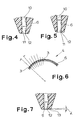
- FIGS. 3, 4 and 5 shows that the outlet section 10 in its end region 11 with different water passage openings 3 can also be designed differently.
- this beam pattern is 10 times in Projection 6 provided so that thirty water passage openings 3 with a Inclination of 8 ° with respect to the vertical, twenty water openings with an inclination of 5 ° and ten water passages with an inclination of 2 ° are provided.
- the one in FIG shown end region 11 has a bevel 12 with an angle of 16 °, so that there is a water jet direction of 8 °.
- 4 shows the bevel 12 in the end region 11 at an angle of 10 °, so that there is a Water jet direction of 5 ° results.
- the water passage openings 3 are designed such that there is an equal flow rate regardless of the water jet direction results. This is realized in that the lower surface of the water passage openings 3 the desired requirements in the area of the outlet accordingly beveled at a small angle ⁇ of 0 to 1 ° is. This results in the area of the bevel 12 subsequent to the End region 11 a protrusion 13 through which the water passage opening narrowed.
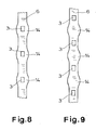
- the inside and / or on the outside of the projection 6 and / or the base part 4 at least one bulge 14 provided.
- the bulges 14 are not only aesthetic Effect, because they give the impression of "rubbing" when stripping lime, but also serve to move the annular bottom part 4 to avoid within the shower head 1. 8 also shows and 9 that the water passage openings 3 at least on their outlet side End in a rectangular shape.
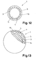
- FIGS. 10 to 13 are other embodiments of the shower head according to the invention 1 shown.
- the bottom part 4 in a lower support element 15 of the shower head 1 inserted and fixed in it.
- the main thing here is that the bottom part 4 has a central section 16 which is designed as a membrane.
- Water passage openings 3 can be aligned as described above.
- the design as a membrane makes it possible, with a correspondingly slight application of pressure to deform the membrane to the central portion 16, which for Removal of the lime deposited there leads.
- the base part 4 an area 7 of approximately U-shaped cross section.
- the middle section 16 lies between the two side legs of the U-shaped Area 7.
- the bottom part 4 is again designed as a ring, which is what the previously mentioned Has advantages.
- the middle section 16 stands over the bottom 5 of the shower head 1 over.
- the middle section 16 presses This is particularly easy if the middle section 16 and the bottom 5 merge into each other.
- the U-shaped region 7 or the bottom part 4 accidentally damaged.
- the central section of the area is also concave or can just be trained.
- a movement of the midsection can result from this result in water flowing through the shower head and the flow pressure on the inside of the central section acts so that it extends outwards bulges. If the water pressure changes now, this occurs due to the membrane properties a corresponding movement of the middle section, which also leads to limescale removal.
- the additional "scratching" to facilitate at least one knob 17 on the outside of the central section 16 may be provided, which over the underside 5 of the shower head 1 survives.
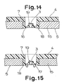
- FIGS. 14 and 15 While the annular design of the base part 4 from FIGS. 12 and 13 14 and 15, another embodiment is shown, in which basically also the central section 16 as a membrane is trained.
- FIGS. 14 and 15 applies to what has been said above with the exception that the bottom part 4 is not considered Ring is formed, has a plurality of middle sections that approximately are distributed over the entire underside 5 of the shower head.
- a plurality of openings 18 are provided in the corresponding Project U-shaped areas 7. Because of the U-shaped design, they are Areas flat and designed so that a user the middle sections 16th (with convex training).
- FIGS. 14 and 15 Concave formation of the middle section 16 applies to what has been said above.
- a collar 19 protruding into the interior of the area 7 is an extension the water passage opening 3 is provided.
- the collar 19 thus represents a reinforcement for the water passage opening 3 towards the inside.
- a corresponding support device 20 provided to fix the annular base parts 4 in the shower head 1 and in the case of a U-shaped design.
- the support device 20 preferably has one circumferential support ring with a plurality of passage openings 21st is provided, as can be seen in particular from FIGS. 10 and 11.
- the Support device 20 clamps the bottom part 4 in the ring channel 8 of the shower head 1 firmly.
- Steps 22 in the U-shaped area 7 for inserting the support device 20 be provided.
Abstract
Description
Die Erfindung betrifft einen Brausekopf mit einem Wasserdurchtrittsöffnungen aufweisenden Bodenteil aus einem elastischen Material, wobei die Wasserdurchtrittsöffnungen an der Unterseite des Brausekopfes austreten und über die Unterseite überstehen.The invention relates to a shower head with a water passage openings having bottom part made of an elastic material, the water passage openings Exit at the bottom of the shower head and over the bottom survive.
Brauseköpfe sind als Teil einer Brause in fast jedem Haushalt zu finden und seit Jahrzehnten bekannt. Probleme ergeben sich bei Brauseköpfen insbesondere bei hartem bis sehr hartem Leitungswasser, aus dem sich sehr rasch und massiv Kalkablagerungen ausscheiden. Die Kalkablagerungen setzen die Wasserdurchtrittsöffnungen zu und beeinträchtigen wesentlich die Funktion des Brausekopfes.Shower heads can be found in almost every household as part of a shower head known for decades. Problems arise in particular with shower heads with hard to very hard tap water, from which very quickly and massively Eliminate limescale. The limescale deposits set the water passage openings and significantly impair the function of the shower head.
Um die an sich nicht zu verhindernden Kalkablagerungen zu beseitigen, sind bereits verschiedene Vorschläge gemacht worden. Aus der EP - A- 0 443 538 ist bereits ein Brausekopf der eingangs genannten Art bekannt, wobei am Bodenteil angeformte Zapfen vorgesehen sind, durch die die Wasserdurchtrittsöffnungen hindurchgeführt sind und die über die Unterseite des Brausekopfes überstehen. Durch ein manuelles "Rubbeln" über die elastisch verformbaren Enden der Zapfen soll eine Entfernung der Kalkverkrustungen möglich sein.In order to remove the limescale deposits that cannot be prevented in themselves Various proposals have already been made. From EP-A-0 443 538 a shower head of the type mentioned is already known, wherein on Bottom part molded pins are provided through which the water passage openings are passed through and over the bottom of the shower head survive. By manually "rubbing" over the elastically deformable ends the cone should be able to remove limescale deposits.
Auf einem ähnlichen Prinzip beruht der aus der EP - A - 0 435 031 bekannte Brausekopf, an dessen Bodenteil schlauchartige Austrittsöffnungen aus einem Werkstoff mit einer Materialhärte von 20 bis 100 shore vorgesehen sind. Durch manuelles "Rubbeln" an den schlauchartigen Austrittsöffnungen soll in diesen abgelagerter Kalk abgelöst werden.The principle known from EP-A-0 435 031 is based on a similar principle Shower head, at the bottom part of which there are hose-like outlet openings Material with a hardness of 20 to 100 shore are provided. By manual "rubbing" on the hose-like outlet openings should be in these deposited lime can be removed.
Sowohl in der EP - A - 0 443 538, als auch in der EP - A - 0 435 031 stehen also die Wasserdurchtrittsöffnungen über zapfen- oder schlauchartige Verlängerungen über die Unterseite des Brausekopfes über. Das Problem bei den bekannten zapfen- oder schlauchartigen Verlängerungen besteht darin, daß es beim manuellen "Rubbeln", insbesondere aufgrund der Dünnwandigkeit der Verlängerungen zum Abknicken, Einreißen oder gänzlichem Abreißen der Verlängerungen kommen kann. Hierdurch kann nicht nur die Funktion des Brausekopfes, sondern auch die Möglichkeit der Beseitigung der Kalkablagerungen wesentlich beeinträchtigt werden.Both in EP-A-0 443 538 and in EP-A-0 435 031 So the water passage openings over cone-like or hose-like extensions over the bottom of the shower head over. The problem with the known cone-like or hose-like extensions is that it manual "rubbing", especially due to the thin walls of the extensions for kinking, tearing or completely tearing off the extensions can come. This can not only function the shower head, but the possibility of removing limescale is also significantly impaired will.
Die Erfindung geht nun einen neuen Weg. Erfindungsgemäß ist bei dem eingangs genannten Brausekopf vorgesehen, daß der Bodenteil einen etwa ringförmig ausgebildeten Vorsprung aufweist, der über die Unterseite des Brausekopfes übersteht und daß die Wasserdurchtrittsöffnungen über die Länge des Vorsprungs verteilt sind. Bei der Erfindung wird also nach wie vor die Möglichkeit des manuellen "Rubbelns" ausgenutzt, um Kalkablagerungen in den Wasserdurchtrittsöffnungen zu beseitigen. Allerdings besteht bei dem erfindungsgemäßen Brausekopf mit dem wenigstens ein Ringsegment, vorzugsweise aber die Form eines geschlossenen Ringes aufweisenden Vorsprung nicht mehr die Gefahr der Beschädigung, die bei den zuvor erwähnten Verlängerungen gegeben ist. Durch den umlaufenden Vorsprung sind die Wasserdurchtrittsöffnungen derart verstärkt, daß die Gefahr der Beschädigung des Bodenteils beim "Rubbeln" nicht mehr besteht. Da der Vorsprung aber aus dem gleichen elastischen Material besteht wie der Bodenteil, läßt sich der ringförmige Vorsprung ohne weiteres durch manuelles "Rubbeln" elastisch verformen, wodurch die Kalkpartikel in den Wasserdurchtrittsöffnungen abgelöst und dann aus diesen herausfallen oder herausgespült werden.The invention now goes a new way. According to the invention at the beginning called shower head provided that the bottom part has an approximately ring-shaped Has projection that protrudes beyond the underside of the shower head and that the water passage openings along the length of the projection are distributed. In the invention, the possibility of manual "rubbing" exploited to limescale deposits in the water passage openings to eliminate. However, there is in the shower head according to the invention with the at least one ring segment, but preferably the shape of a projection having a closed ring no longer carries the risk of damage, which is the case with the aforementioned extensions. By the circumferential projection, the water passage openings are reinforced in such a way that the risk of damage to the bottom part when "rubbing" is not more exists. But since the projection is made of the same elastic material like the bottom part, the annular projection can be easily made deform by manual "rubbing", whereby the lime particles in the Water passage openings detached and then fall out of them or be washed out.
Bei einer alternativen Ausführungsform ist vorgesehen, daß der Bodenteil wenigstens einen an der Unterseite des Brausekopfes freiliegenden, zumindest eine Wasserdurchtrittsöffnung aufweisenden Mittelabschnitt aufweist, der als Membran ausgebildet ist. Aufgrund der elastischen Eigenschaften des Bodenteils und der Ausbildung des Mittelabschnitts als Membran, wobei die Wasserdurchtrittsöffnungen nicht unbedingt über die Unterseite des Brausekopfes überstehen müssen, läßt sich eine Reinigung des Brausekopfes von den Kalkpartikeln in besonders einfacher Weise dadurch erreichen, daß man beispielsweise mit einem Finger über den membranartig ausgebildeten freiliegenden, d. h. für den Benutzer von außen frei zugänglichen Mittelabschnitt streicht und auf diesen gleichzeitig einen geringen Druck ausübt, so daß aufgrund der Elastizität des Materials des Bodenteils der Mittelabschnitt in den Brausekopf hineingedrückt wird, was zu einer Verformung des Mittelabschnitts und der darin befindlichen Wasserdurchtrittsöffnungen und damit zu einer Ablösung von Kalkablagerungen führt. Auch bei dieser Ausführungsform ist eine Beschädigung des Bodenteils mit einer damit verbundenen Beeinträchtigung der Brausefunktion des Brausekopfes nicht zu befürchten.In an alternative embodiment it is provided that the bottom part at least one exposed at the bottom of the shower head, at least has a water passage opening having a central section, which as Membrane is formed. Due to the elastic properties of the bottom part and the formation of the central section as a membrane, the water passage openings do not necessarily have to protrude over the underside of the shower head, can be a cleaning of the shower head from the lime particles in particular easily achieved by, for example, a finger over the membrane-like exposed, d. H. for the user from outside freely accessible middle section strokes and at the same time one exerts little pressure, so that due to the elasticity of the material of the bottom part the middle section is pressed into the shower head, resulting in a Deformation of the middle section and the water passage openings located therein and thus leads to the removal of limescale deposits. Also at this embodiment is damage to the bottom part with a so associated fear of the shower function of the shower head.
Weitere Merkmale, Vorteile und Anwendungsmöglichkeiten der vorliegenden Erfindung ergeben sich aus den Unteransprüchen, der nachfolgenden Beschreibung von Ausführungsbeispielen anhand der Zeichnung und der Zeichnung selbst. Dabei bilden alle beschriebenen und/oder bildlich dargestellten Merkmale für sich oder in beliebiger Kombination den Gegenstand der vorliegenden Erfindung unabhängig von ihrer Zusammenfassung in den Patentansprüchen oder deren Rückbeziehung.Further features, advantages and possible uses of the present invention result from the subclaims, the following description of exemplary embodiments based on the drawing and the drawing itself form all described and / or illustrated features for themselves or in any combination the subject of the present invention regardless of their summary in the claims or their Relationship.
Es zeigt
- Fig. 1
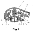
- eine Querschnittsansicht eines erfindungsgemäßen Brausekopfes, in dem zwei unterschiedliche Ausführungsformen dargestellt sind,
- Fig. 2
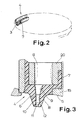
- eine perspektivische Querschnittsansicht eines nur teilweise dargestellten erfindungsgemäßen Bodenteils,
- Fig. 3
- eine Querschnittsansicht eines Teils eines erfindungsgemäßen Brausekopfes,
- Fig. 4
- eine Querschnittsansicht eines Teils des Bodenteils mit einer Wasserdurchtrittsöffnung,
- Fig. 5
- eine Querschnittsansicht eines anderen Teils des erfindungsgemäßen Bodenteils mit einer anderen Wasserdurchtrittsöffnung,
- Fig. 6
- eine schematische Darstellung des Strahlbildes des erfindungsgemäßen Brausekopfes,
- Fig. 7
- eine Querschnittsansicht eines Teils des Bodenteils,
- Fig. 8
- eine gestreckte Ansicht eines ringförmigen Vorsprungs des erfindungsgemäßen Bodenteils,
- Fig. 9
- eine weitere gestreckte Ansicht einer anderen Ausführungsform des erfindungsgemäßen Bodenteils,
- Fig. 10
- eine perspektivische Querschnittsansicht eines Teils einer anderen Ausführungsform des erfindungsgemäßen Brausekopfes,
- Fig. 11
- eine der Fig. 9 entsprechende Ansicht einer weiteren Ausführungsform des erfindungsgemäßen Brausekopfes,
- Fig. 12
- eine Unteransicht eines erfindungsgemäßen Brausekopfes,
- Fig. 13
- eine weitere Unteransicht einer anderen Ausführungsform des erfindungsgemäßen Brausekopfes,
- Fig. 14
- eine Querschnittsansicht einer weiteren Ausführungsform des erfindungsgemäßen Brausekopfes und
- Fig. 15
- eine Querschnittsansicht einer weiteren Ausführungsform des erfindungsgemäßen Brausekopfes.
- Fig. 1
- 2 shows a cross-sectional view of a shower head according to the invention, in which two different embodiments are shown,
- Fig. 2
- 2 shows a perspective cross-sectional view of a base part according to the invention which is only partially shown,
- Fig. 3
- 2 shows a cross-sectional view of part of a shower head according to the invention,
- Fig. 4
- 2 shows a cross-sectional view of part of the base part with a water passage opening,
- Fig. 5
- 2 shows a cross-sectional view of another part of the base part according to the invention with a different water passage opening,
- Fig. 6
- 2 shows a schematic representation of the spray pattern of the shower head according to the invention,
- Fig. 7
- a cross-sectional view of part of the bottom part,
- Fig. 8
- 2 shows a stretched view of an annular projection of the base part according to the invention,
- Fig. 9
- FIG. 2 shows another extended view of another embodiment of the base part according to the invention,
- Fig. 10
- 2 shows a perspective cross-sectional view of part of another embodiment of the shower head according to the invention,
- Fig. 11
- 9 shows a view corresponding to FIG. 9 of a further embodiment of the shower head according to the invention,
- Fig. 12
- a bottom view of a shower head according to the invention,
- Fig. 13
- another bottom view of another embodiment of the shower head according to the invention,
- Fig. 14
- a cross-sectional view of another embodiment of the shower head according to the invention and
- Fig. 15
- a cross-sectional view of a further embodiment of the shower head according to the invention.
In Fig. 1 ist ein erfindungsgemäßer Brausekopf 1 in Querschnittsansicht dargestellt.
Der Brausekopf 1, dessen grundsätzlicher Aufbau an sich bekannt
ist, weist eine Wasserzuführung 2 auf. Weiterhin ist der Brausekopf 1 mit
einem Wasserdurchtrittsöffnungen 3 aufweisenden Bodenteil 4 versehen. Der
Bodenteil 4 besteht aus elastischem Material, vorzugsweise mit einer Materialhärte
von 20 bis 120 shore. Die Wasserdurchtrittsöffnungen 3 treten an der
Unterseite 5 des Brausekopfes 1 aus. Außerdem stehen die Wasserdurchtrittsöffnungen
3 zumindest bei der rechten Ausführungsform gemäß Fig. 1 über die
Unterseite 5 des Brausekopfes 1 über. Bei der in Fig. 1 dargestellten linken
Ausführungsform stehen die Wasserdurchtrittsöffnungen 3, wenn überhaupt, nur
ganz geringfügig über die Unterseite 5 des Brausekopfes 1 über. Der Bodenteil 4
an sich ist im Brausekopf 1 gehalten und steht mit der Wasserzuführung 2 in
Verbindung.In Fig. 1 a
Wesentlich ist nun, daß der Bodenteil 4 wenigstens einen etwa ringförmig ausgebildeten
Vorsprung 6 aufweist, der über die Unterseite 5 des Brausekopfes 1
übersteht, wobei die Wasserdurchtrittsöffnungen 3 über die Länge des Vorsprungs 6
verteilt angeordnet sind. Der Vorsprung 6 an sich weist wenigstens ein Ringsegment
auf, das sich zumindest über einen Teil der Unterseite 5 des Brausekopfes 1
umfangartig erstreckt. Vorzugsweise weist der Vorsprung 6 aber die Form eines
geschlossenen Ringes auf, der umfangsmäßig an der Unterseite 5 des Brausekopfes
1 angeordnet ist. Im übrigen versteht es sich aber auch, daß der Vorsprung 6
die Form eines geöffneten Ringes haben kann.It is essential that the
Der ringförmige Vorsprung, der an sich aus Vollmaterial besteht und lediglich
an einigen Stellen von den Wasserdurchtrittsöffnungen durchstoßen ist, kann
aufgrund der Materialeigenschaften des Bodenteils 4 ohne weiteres manuell
durch "Rubbeln" verformt werden, wobei sich auch die Wasserdurchtrittsöffnungen
3 in ihrer Form verändern, was zur Folge hat, daß sich darin abgelagerter
Kalk löst und ausgetragen wird. Die Wasserdurchtrittsöffnungen 3 treten jeweils
an der höchsten Stelle des Vorsprungs 6 aus, sind also zumindest in Umfangsrichtung
von vergleichsweise viel elastischem Material des Bodenteils 4 umgeben,
so daß ein Abbrechen bzw. eine Beschädigung des Vorsprungs beim "Rubbeln"
nicht zu befürchten ist.The ring-shaped projection, which consists of solid material and only
is penetrated by the water passage openings in some places
due to the material properties of the
Um eine gute Wasserverteilung des Brausekopfes 1 zu gewährleisten, bietet es
sich an, die Wasserdurchtrittsöffnungen 3 über den Umfang des Vorsprungs 6
gleichmäßig zu verteilen. Dabei ist festgestellt worden, daß es für ein gutes
Strahlergebnis ausreichend ist, wenn die einzelnen Wasserdurchtrittsöffnungen 3
um einen Bogenwinkel von 6° beabstandet sind. Auf diese Weise erhält man 60
Wasserdurchtrittsöffnungen 3, wobei aufgrund der erfindungsgemäßen Funktion
sichergestellt ist, daß immer alle 60 Wasserdurchtrittsöffnungen nach gelegentlichem
"Rubbeln" durchströmt werden.To ensure a good water distribution of the
Wie insbesondere aus Fig. 2 erkennbar ist, ist nicht nur der Vorsprung 6 ringförmig
ausgebildet, sondern auch der Bodenteil 4. Es ist also nicht unbedingt
erforderlich, daß sich der Bodenteil 4 über die gesamte Fläche der Unterseite 5
des Brausekopfes 1 erstreckt. Durch den ringförmigen Bodenteil 4 ist es also
möglich, die eigentliche Brausefunktion in den Bereich des äußeren Umfanges
des Brausekopfes 1 zu verlegen, während der mittige Bereich für mögliche andere
Funktionen des Brausekopfes 1 zur Verfügung steht.As can be seen in particular from FIG. 2, not only the
Wie insbesondere in den Fig. 1 bis 3, 10 und 11 sowie 14 und 15 erkennbar ist,
weist der Bodenteil 4 einen im Querschnitt etwa U-förmig ausgebildeten Bereich
7 auf, an den sich bei den Ausführungsformen der Fig. 1 (rechte Darstellung)
sowie Fig. 2 und 3 der Vorsprung 6 anschließt. Durch die U-förmige
Ausbildung des Bereichs 7 läßt sich der Bodenteil 4 in besonders einfacher
Weise in einem im Gehäuse des Brausekopfes 1 vorgesehenen Ringkanal 8 halten,
worauf weiter unten noch näher eingegangen wird. Außerdem läßt sich der
Vorsprung 6 aufgrund des U-förmigen Bereichs 7 gut in den Brausekopf 1 hineindrücken,
was das Ablösen von Kalk erleichtert. Es versteht sich, daß der
Bodenteil 4 aber auch an sich als Ringscheibe ausgebildet sein kann, an die
sich der Vorsprung 6 nach unten hin anschließt. Statt einer seitlichen Klemmung
über den U-förmigen Bereich ist der Bodenteil 4 dann in entsprechender
Weise im Gehäuse des Brausekopfes 1 zu halten bzw. zu klemmen. Wichtig
ist, daß der Vorsprung 6 nicht nur hin- und herbewegbar, sondern auch in den
Brausekopf 1 hineindrückbar ist.As can be seen in particular in FIGS. 1 to 3, 10 and 11 and 14 and 15,
the
Die Wasserdurchtrittsöffnungen 3 weisen einen sich in Durchflußrichtung verengenden
Abschnitt 9 auf. Dieser sich verengende Abschnitt 9 wirkt in Art
einer Venturi-Düse, führt also zur Beschleunigung des Wassers. Der Vorteil
dieses sich verengenden Abschnitts 9 liegt darin, daß auch bei einer geringen
Wassermenge ein recht kräftiger Wasserstrahl erzeugt werden kann.
Der sich verengende Abschnitt 9 schließt sich unmittelbar an den U-förmigen
Bereich 7 an. An den sich verengenden Abschnitt 9 wiederum schließt sich
ein Austrittsabschnitt 10 an. In seinem Endbereich 11 ist der Austrittsabschnitt
10 entsprechend der gewünschten Wasseraustrittsrichtung angeschrägt.
Dabei zeigt ein Vergleich der Fig. 3, 4 und 5, daß der Austrittsabschnitt 10
in seinem Endbereich 11 bei unterschiedlichen Wasserdurchtrittsöffnungen 3
auch unterschiedlich ausgebildet sein kann.The
Vorzugsweise ist um ein gutes Strahlbild des Brausekopfes 1 zu erhalten, vorgesehen,
daß benachbarte Wasserdurchtrittsöffnungen 3 unterschiedliche Wasserstrahlrichtungen
aufweisen. Dies wird über entsprechende Anschrägungen 12 im
Endbereich 11 der jeweiligen Wasserdurchtrittsöffnungen 3 erreicht. Bei Versuchen
ist festgestellt worden, daß gute Strahlergebnisse erreicht werden, wenn
die Wasserstrahlrichtung der einzelnen Wasserdurchtrittsöffnungen 3 zwischen
0 und 16° liegt, wobei in einer besonders bevorzugten Ausführungsform ein sich
periodisch wiederholendes Strahlbild mit Wasserstrahlrichtungen der einzelnen
Wasserdurchtrittsöffnungen 3 von 8°, 5°, 8°, 5°, 8° und 2° vorgesehen ist (vgl.
Fig. 6). Bei dem erwähnten Bogenwinkel von 6° ist dieses Strahlbild 10 mal im
Vorsprung 6 vorgesehen, so daß dreißig Wasserdurchtrittsöffnungen 3 mit einer
Neigung von 8° gegenüber der Senkrechten, zwanzig Wasserdurchtrittsöffnungen mit
einer Neigung von 5° und zehn Wasserdurchtrittsöffnungen mit einer Neigung von
2° vorgesehen sind. Im dargestellten Ausführungsbeispiel weist der in Fig. 3
dargestellte Endbereich 11 eine Anschrägung 12 mit einem Winkel von 16° auf,
so daß sich eine Wasserstrahlrichtung von 8° ergibt. In Fig. 4 weist die Anschrägung
12 im Endbereich 11 einen Winkel von 10° auf, so daß sich hier eine
Wasserstrahlrichtung von 5° ergibt. Schließlich ist bei der in Fig. 5 dargestellten
Ausführungsform die Anschrägung 12 unter einem Winkel von 4° gegenüber
der Senkrechten geneigt, so daß sich eine Wasserstrahlrichtung von 2°
ergibt. Der sich verengende Abschnitt 9 ist bei jeder einzelnen Wasserdurchtrittsöffnung
3 gleich. In Abhängigkeit der gewünschten Wasserstrahlrichtung
ist der Austrittsabschnitt 10 bei den einzelnen Wasserdurchtrittsöffnungen
unterschiedlich ausgebildet, der Endbereich 11 also länger oder kürzer.Preferably, in order to obtain a good spray pattern of the
Aufgrund der unterschiedlichen Ausbildung der Austrittsabschnitte 10 bzw.
der einzelnen Endbereiche 11 können sich unterschiedliche Strömungswiderstände
ergeben. Die Wasserdurchtrittsöffnungen 3 sind jedoch derart ausgebildet,
daß sich unabhängig von der Wasserstrahlrichtung eine gleiche Durchflußrate
ergibt. Dies ist dadurch realisiert, daß die untere Fläche der Wasserdurchtrittsöffnungen
3 im Bereich des Austritts den gewünschten Erfordernissen
entsprechend unter einem kleinen Winkel α von 0 bis 1° angeschrägt
ist. Hierdurch ergibt sich im Bereich der Anschrägung 12 anschließend an den
Endbereich 11 ein Überstand 13, durch den sich die Wasserdurchtrittsöffnung
verengt.Due to the different design of the
Wie sich insbesondere aus den Fig. 8, 9 und 13 ergibt, ist innenseitig und/oder
außenseitig des Vorsprungs 6 und/oder des Bodenteils 4 wenigstens eine Ausbuchtung
14 vorgesehen. Die Ausbuchtungen 14 haben nicht nur einen ästhetischen
Effekt, sie vermitteln nämlich beim Abstreifen von Kalk den Eindruck des "Rubbelns",
sondern dienen auch dazu, ein Verschieben des ringförmigen Bodenteils 4
innerhalb des Brausekopfes 1 zu vermeiden. Außerdem ergibt sich aus den Fig. 8
und 9, daß die Wasserdurchtrittsöffnungen 3 zumindest an ihrem austrittsseitigen
Ende eine Rechteckform aufweisen.As can be seen in particular from FIGS. 8, 9 and 13, the inside and / or
on the outside of the
In den Fig. 10 bis 13 sind andere Ausführungsformen des erfindungsgemäßen Brausekopfes
1 dargestellt. Bei der in den Fig. 10 und 11 dargestellten Ausführungsform
ist der Bodenteil 4 in ein unteres Trägerelement 15 des Brausekopfes 1
eingelegt und darin fixiert. Wesentlich ist hierbei vor allem, daß der Bodenteil
4 einen Mittelabschnitt 16 aufweist, der als Membran ausgebildet ist. In
diesem Mittelabschnitt 16 befinden sich die Wasserdurchtrittsöffnungen 3. Die
Wasserdurchtrittsöffnungen 3 können wie zuvor beschrieben ausgerichtet sein.
Die Ausbildung als Membran ermöglicht es, bei entsprechend geringfügiger Druck-Druckausübung
auf den Mittelabschnitt 16 die Membran zu verformen, was zum
Ablösen des sich dort abgelagerten Kalks führt.10 to 13 are other embodiments of the shower head according to the
Aus den erwähnten Gründen der einfachen Befestigung weist der Bodenteil 4
einen im Querschnitt etwa U-förmig ausgebildeten Bereich 7 auf. Der Mittelabschnitt
16 liegt dabei zwischen den beiden seitlichen Schenkeln des U-förmigen
Bereichs 7. Auch in den dargestellten Ausführungsbeispielen der Fig. 10
und 11 ist der Bodenteil 4 wiederum als Ring ausgebildet, was die zuvor erwähnten
Vorteile hat. Bei beiden Ausführungsformen steht der Mittelabschnitt 16
über die Unterseite 5 des Brausekopfes 1 über. Bei diesen Ausführungsformen
kann das "Rubbeln" in besonders einfacher Weise erfolgen, indem man lediglich
über die Unterseite 5 des Brausekopfes 1 streicht und dabei den Mittelabschnitt
16 eindrückt. Dies ist besonders einfach dann möglich, wenn der Mittelabschnitt
16 und die Unterseite 5 stufenlos ineinander übergehen. Hierdurch
kann auch vermieden werden, daß der U-förmige Bereich 7 bzw. der Bodenteil
4 unbeabsichtigt beschädigt werden.For the reasons of simple attachment mentioned, the
Nicht dargestellt ist, daß der Mittelabschnitt des Bereichs auch konkav oder
eben ausgebildet sein kann. Bei der konkaven oder ebenen Ausbildung des Mittelabschnitts
kann sich eine Bewegung des Mittelabschnitts schon dadurch
ergeben, daß Wasser durch den Brausekopf strömt und der Strömungsdruck auf
die Innenseite des Mittelabschnitts wirkt, so daß sich dieser nach außen
wölbt. Verändert sich der Wasserdruck nun, tritt aufgrund der Membraneigenschaften
des Mittelabschnitts eine entsprechende Bewegung auf, die ebenfalls
zur Kalkablösung führt. In jedem Fall kann, aber um das zusätzliche "Rubbeln"
zu erleichtern, wenigstens ein Noppen 17 auf der Außenseite des Mittelabschnitts
16 vorgesehen sein, der über die Unterseite 5 des Brausekopfes 1
übersteht.It is not shown that the central section of the area is also concave or
can just be trained. In the concave or flat design of the middle section
a movement of the midsection can result from this
result in water flowing through the shower head and the flow pressure on
the inside of the central section acts so that it extends outwards
bulges. If the water pressure changes now, this occurs due to the membrane properties
a corresponding movement of the middle section, which also
leads to limescale removal. In any case, but for the additional "scratching"
to facilitate at least one
Während aus den Fig. 12 und 13 die ringförmige Ausbildung des Bodenteils 4
gut hervorgeht, ist in den Fig. 14 und 15 eine andere Ausführungsform gezeigt,
bei der grundsätzlich ebenfalls der Mittelabschnitt 16 als Membran
ausgebildet ist. Für die in den Fig. 14 und 15 dargestellten Ausführungsformen
gilt an sich das zuvor Gesagte mit der Ausnahme, daß der Bodenteil 4 nicht als
Ring ausgebildet ist, eine Vielzahl von Mittelabschnitten aufweist, die etwa
über die gesamte Unterseite 5 des Brausekopfes verteilt sind. Im Trägerelement
15 sind eine Vielzahl von Öffnungen 18 vorgesehen, in die entsprechende
U-förmige Bereiche 7 hineinragen. Aufgrund der U-förmigen Ausbildung sind die
Bereiche flächig und so ausgelegt, daß ein Benutzer die Mittelabschnitte 16
(bei konvexer Ausbildung) eindrücken kann. Bei der in den Fig. 14 und 15 dargestellten
konkaven Ausbildung des Mittelabschnitts 16 gilt das zuvor Gesagte.While the annular design of the
Um die in den einzelnen Bereichen 7 vorgesehenen Wasserdurchtrittsöffnungen 3
keiner unbeabsichtigten Beschädigung durch den manuellen Druck von außen und/
oder den Wasserdruck und der damit verbundenen Bewegung des Mittelabschnitts 16
auszusetzen, ist ein in das Innere des Bereichs 7 ragender Kragen 19 in Verlängerung
der Wasserdurchtrittsöffnung 3 vorgesehen. Der Kragen 19 stellt also
eine Verstärkung für die Wasserdurchtrittsöffnung 3 nach innen hin dar.Around the
Um insbesondere die ringförmigen Bodenteile 4 im Brausekopf 1 zu fixieren und
bei U-förmiger Ausbildung offen zu halten, ist eine entsprechende Stützeinrichtung
20 vorgesehen. Die Stützeinrichtung 20 weist vorzugsweise einen
umlaufenden Stützring auf, der mit einer Vielzahl von Durchtrittsöffnungen 21
versehen ist, wie dies inbesondere aus den Fig. 10 und 11 hervorgeht. Die
Stützeinrichtung 20 klemmt den Bodenteil 4 im Ringkanal 8 des Brausekopfes 1
fest. Hierzu können, wie dies aus den Fig. 10 und 11 hervorgeht, entsprechende
Stufen 22 im U-förmigen Bereich 7 zum Einsetzen der Stützeinrichtung 20
vorgesehen sein.In particular, to fix the
Claims (7)
Applications Claiming Priority (5)
| Application Number | Priority Date | Filing Date | Title |
|---|---|---|---|
| DE4404966A DE4404966C2 (en) | 1994-02-17 | 1994-02-17 | Base part for a shower head |
| DE4404966 | 1994-02-17 | ||
| DE4419696 | 1994-06-04 | ||
| DE4419696A DE4419696C2 (en) | 1994-06-04 | 1994-06-04 | Shower head |
| EP95912160A EP0744997B1 (en) | 1994-02-17 | 1995-02-17 | Base part for a spray head, and spray head |
Related Parent Applications (2)
| Application Number | Title | Priority Date | Filing Date |
|---|---|---|---|
| EP95912160A Division-Into EP0744997B1 (en) | 1994-02-17 | 1995-02-17 | Base part for a spray head, and spray head |
| EP95912160.9 Division | 1995-08-24 |
Publications (3)
| Publication Number | Publication Date |
|---|---|
| EP0878237A2 true EP0878237A2 (en) | 1998-11-18 |
| EP0878237A3 EP0878237A3 (en) | 1998-12-30 |
| EP0878237B1 EP0878237B1 (en) | 2001-07-11 |
Family
ID=6510417
Family Applications (1)
| Application Number | Title | Priority Date | Filing Date |
|---|---|---|---|
| EP98110812A Revoked EP0878237B1 (en) | 1994-02-17 | 1995-02-17 | Base part for spray head, and spray head |
Country Status (2)
| Country | Link |
|---|---|
| EP (1) | EP0878237B1 (en) |
| DE (3) | DE4404966C2 (en) |
Cited By (1)
| Publication number | Priority date | Publication date | Assignee | Title |
|---|---|---|---|---|
| WO2004085753A1 (en) | 2003-03-25 | 2004-10-07 | Neoperl Gmbh | Sanitary water discharge unit, especially jet regulator or shower |
Families Citing this family (3)
| Publication number | Priority date | Publication date | Assignee | Title |
|---|---|---|---|---|
| DE19646655A1 (en) * | 1996-11-12 | 1998-05-14 | Grohe Kg Hans | Shower head |
| DE19901554A1 (en) * | 1999-01-16 | 2000-07-20 | Hansgrohe Ag | Shower head |
| DE102004056070B4 (en) * | 2004-11-15 | 2019-01-31 | Hansgrohe Se | Sanitary shower head |
Citations (2)
| Publication number | Priority date | Publication date | Assignee | Title |
|---|---|---|---|---|
| EP0435031A2 (en) | 1989-12-28 | 1991-07-03 | Friedrich Grohe Aktiengesellschaft | Shower head |
| EP0443538A1 (en) | 1990-02-22 | 1991-08-28 | MASCO GmbH | Shower head |
Family Cites Families (9)
| Publication number | Priority date | Publication date | Assignee | Title |
|---|---|---|---|---|
| US2402741A (en) * | 1944-10-03 | 1946-06-25 | Adolphe O Draviner | Spray head |
| US2559894A (en) * | 1948-02-25 | 1951-07-10 | Carl H Nordell | Shower head |
| FR1070363A (en) * | 1953-02-06 | 1954-07-23 | Shower device | |
| CH645176A5 (en) * | 1980-11-19 | 1984-09-14 | Kaeser Charles Sa | AUTOMATIC MIXER DEVICE. |
| DE3044310C2 (en) * | 1980-11-25 | 1984-09-27 | Friedrich Grohe Armaturenfabrik Gmbh & Co, 5870 Hemer | Shower equipment |
| DE3704782A1 (en) * | 1986-12-04 | 1988-09-15 | Johannes Neuenschwander | Economy shower with elastic head and economy nozzle |
| JPH0499243U (en) * | 1991-01-17 | 1992-08-27 | ||
| DE4308599A1 (en) * | 1992-11-04 | 1994-05-05 | Grohe Armaturen Friedrich | Shower head |
| DE9310367U1 (en) * | 1993-07-12 | 1993-09-02 | Hamm Manfred R Dr | Massage shower head with rotating knob-coated surface |
-
1994
- 1994-02-17 DE DE4404966A patent/DE4404966C2/en not_active Expired - Fee Related
-
1995
- 1995-02-17 DE DE59509619T patent/DE59509619D1/en not_active Expired - Fee Related
- 1995-02-17 DE DE59509412T patent/DE59509412D1/en not_active Revoked
- 1995-02-17 EP EP98110812A patent/EP0878237B1/en not_active Revoked
Patent Citations (2)
| Publication number | Priority date | Publication date | Assignee | Title |
|---|---|---|---|---|
| EP0435031A2 (en) | 1989-12-28 | 1991-07-03 | Friedrich Grohe Aktiengesellschaft | Shower head |
| EP0443538A1 (en) | 1990-02-22 | 1991-08-28 | MASCO GmbH | Shower head |
Cited By (1)
| Publication number | Priority date | Publication date | Assignee | Title |
|---|---|---|---|---|
| WO2004085753A1 (en) | 2003-03-25 | 2004-10-07 | Neoperl Gmbh | Sanitary water discharge unit, especially jet regulator or shower |
Also Published As
| Publication number | Publication date |
|---|---|
| EP0878237A3 (en) | 1998-12-30 |
| DE4404966A1 (en) | 1995-08-31 |
| DE4404966C2 (en) | 1997-02-13 |
| EP0878237B1 (en) | 2001-07-11 |
| DE59509412D1 (en) | 2001-08-16 |
| DE59509619D1 (en) | 2001-10-25 |
Similar Documents
| Publication | Publication Date | Title |
|---|---|---|
| DE4105183C2 (en) | Shower head | |
| EP0719586B1 (en) | Shower head | |
| EP0719589B1 (en) | Shower head | |
| DE1913713A1 (en) | Spray nozzle | |
| EP0216319A2 (en) | Aerator for the nozzle of a water tap | |
| DE2235217A1 (en) | SHOWER SYSTEM WITH DEVICE FOR REGULATING THE AMPLITUDE OF THE WATER JET | |
| DE3832426C2 (en) | ||
| EP0591877B1 (en) | Shower with self-cleaning shower head | |
| DE2610691B2 (en) | Device for guiding the pulp suspension in a headbox of a paper machine | |
| EP0878237A2 (en) | Base part for spray head, and spray head | |
| EP0744997B1 (en) | Base part for a spray head, and spray head | |
| DE1927695A1 (en) | Outflow mouthpiece for low-splash currents | |
| DE4419696C2 (en) | Shower head | |
| EP0995373B1 (en) | Device for assembling multi-function chairs in a row | |
| DE19646655A1 (en) | Shower head | |
| EP0885660B1 (en) | Shower head | |
| DE2710184C2 (en) | Locking device | |
| EP0646679A1 (en) | Strainer for water taps | |
| DE2111829C3 (en) | Self-cleaning spray head | |
| DE3425660A1 (en) | NOZZLE FOR PLASTIC SPRAYING MACHINES | |
| DE3304480C1 (en) | Clip for holding together sheets of paper or the like | |
| DE1459518A1 (en) | Device for aerating water flowing under pressure | |
| DE202014101221U1 (en) | toilet brush | |
| WO2022194629A1 (en) | Set for protecting a water pipe | |
| DE738277C (en) | Matrix for dental purposes |
Legal Events
| Date | Code | Title | Description |
|---|---|---|---|
| PUAI | Public reference made under article 153(3) epc to a published international application that has entered the european phase |
Free format text: ORIGINAL CODE: 0009012 |
|
| PUAL | Search report despatched |
Free format text: ORIGINAL CODE: 0009013 |
|
| 17P | Request for examination filed |
Effective date: 19980713 |
|
| AC | Divisional application: reference to earlier application |
Ref document number: 744997 Country of ref document: EP |
|
| AK | Designated contracting states |
Kind code of ref document: A2 Designated state(s): DE FR IT |
|
| AK | Designated contracting states |
Kind code of ref document: A3 Designated state(s): DE FR IT |
|
| 17Q | First examination report despatched |
Effective date: 19990907 |
|
| GRAG | Despatch of communication of intention to grant |
Free format text: ORIGINAL CODE: EPIDOS AGRA |
|
| GRAG | Despatch of communication of intention to grant |
Free format text: ORIGINAL CODE: EPIDOS AGRA |
|
| GRAH | Despatch of communication of intention to grant a patent |
Free format text: ORIGINAL CODE: EPIDOS IGRA |
|
| RAP1 | Party data changed (applicant data changed or rights of an application transferred) |
Owner name: IDEAL-STANDARD GMBH & CO. OHG |
|
| GRAH | Despatch of communication of intention to grant a patent |
Free format text: ORIGINAL CODE: EPIDOS IGRA |
|
| GRAA | (expected) grant |
Free format text: ORIGINAL CODE: 0009210 |
|
| AC | Divisional application: reference to earlier application |
Ref document number: 744997 Country of ref document: EP |
|
| AK | Designated contracting states |
Kind code of ref document: B1 Designated state(s): DE FR IT |
|
| PG25 | Lapsed in a contracting state [announced via postgrant information from national office to epo] |
Ref country code: IT Free format text: LAPSE BECAUSE OF FAILURE TO SUBMIT A TRANSLATION OF THE DESCRIPTION OR TO PAY THE FEE WITHIN THE PRESCRIBED TIME-LIMIT;WARNING: LAPSES OF ITALIAN PATENTS WITH EFFECTIVE DATE BEFORE 2007 MAY HAVE OCCURRED AT ANY TIME BEFORE 2007. THE CORRECT EFFECTIVE DATE MAY BE DIFFERENT FROM THE ONE RECORDED. Effective date: 20010711 Ref country code: FR Free format text: LAPSE BECAUSE OF FAILURE TO SUBMIT A TRANSLATION OF THE DESCRIPTION OR TO PAY THE FEE WITHIN THE PRESCRIBED TIME-LIMIT Effective date: 20010711 |
|
| REF | Corresponds to: |
Ref document number: 59509412 Country of ref document: DE Date of ref document: 20010816 |
|
| EN | Fr: translation not filed | ||
| PLBI | Opposition filed |
Free format text: ORIGINAL CODE: 0009260 |
|
| PLBF | Reply of patent proprietor to notice(s) of opposition |
Free format text: ORIGINAL CODE: EPIDOS OBSO |
|
| 26 | Opposition filed |
Opponent name: FRIEDRICH GROHE AG & CO. KG Effective date: 20020330 |
|
| PLBF | Reply of patent proprietor to notice(s) of opposition |
Free format text: ORIGINAL CODE: EPIDOS OBSO |
|
| PLBF | Reply of patent proprietor to notice(s) of opposition |
Free format text: ORIGINAL CODE: EPIDOS OBSO |
|
| PLBF | Reply of patent proprietor to notice(s) of opposition |
Free format text: ORIGINAL CODE: EPIDOS OBSO |
|
| PLBQ | Unpublished change to opponent data |
Free format text: ORIGINAL CODE: EPIDOS OPPO |
|
| PLAB | Opposition data, opponent's data or that of the opponent's representative modified |
Free format text: ORIGINAL CODE: 0009299OPPO |
|
| PLBI | Opposition filed |
Free format text: ORIGINAL CODE: 0009260 |
|
| 26 | Opposition filed |
Opponent name: GROHE WATER TECHNOLOGY AG & CO. KG Effective date: 20020330 |
|
| PLAY | Examination report in opposition despatched + time limit |
Free format text: ORIGINAL CODE: EPIDOSNORE2 |
|
| PLAY | Examination report in opposition despatched + time limit |
Free format text: ORIGINAL CODE: EPIDOSNORE2 |
|
| PLAY | Examination report in opposition despatched + time limit |
Free format text: ORIGINAL CODE: EPIDOSNORE2 |
|
| PLAY | Examination report in opposition despatched + time limit |
Free format text: ORIGINAL CODE: EPIDOSNORE2 |
|
| PLAY | Examination report in opposition despatched + time limit |
Free format text: ORIGINAL CODE: EPIDOSNORE2 |
|
| PGFP | Annual fee paid to national office [announced via postgrant information from national office to epo] |
Ref country code: DE Payment date: 20050128 Year of fee payment: 11 |
|
| PLAY | Examination report in opposition despatched + time limit |
Free format text: ORIGINAL CODE: EPIDOSNORE2 |
|
| RDAF | Communication despatched that patent is revoked |
Free format text: ORIGINAL CODE: EPIDOSNREV1 |
|
| RDAG | Patent revoked |
Free format text: ORIGINAL CODE: 0009271 |
|
| STAA | Information on the status of an ep patent application or granted ep patent |
Free format text: STATUS: PATENT REVOKED |
|
| 27W | Patent revoked |
Effective date: 20050807 |