EP0879665B1 - Welding power supply - Google Patents
Welding power supply Download PDFInfo
- Publication number
- EP0879665B1 EP0879665B1 EP98303877A EP98303877A EP0879665B1 EP 0879665 B1 EP0879665 B1 EP 0879665B1 EP 98303877 A EP98303877 A EP 98303877A EP 98303877 A EP98303877 A EP 98303877A EP 0879665 B1 EP0879665 B1 EP 0879665B1
- Authority
- EP
- European Patent Office
- Prior art keywords
- output
- welding
- inverter
- generator
- power supply
- Prior art date
- Legal status (The legal status is an assumption and is not a legal conclusion. Google has not performed a legal analysis and makes no representation as to the accuracy of the status listed.)
- Expired - Lifetime
Links
Images


Classifications
-
- B—PERFORMING OPERATIONS; TRANSPORTING
- B23—MACHINE TOOLS; METAL-WORKING NOT OTHERWISE PROVIDED FOR
- B23K—SOLDERING OR UNSOLDERING; WELDING; CLADDING OR PLATING BY SOLDERING OR WELDING; CUTTING BY APPLYING HEAT LOCALLY, e.g. FLAME CUTTING; WORKING BY LASER BEAM
- B23K9/00—Arc welding or cutting
- B23K9/095—Monitoring or automatic control of welding parameters
- B23K9/0956—Monitoring or automatic control of welding parameters using sensing means, e.g. optical
-
- B—PERFORMING OPERATIONS; TRANSPORTING
- B23—MACHINE TOOLS; METAL-WORKING NOT OTHERWISE PROVIDED FOR
- B23K—SOLDERING OR UNSOLDERING; WELDING; CLADDING OR PLATING BY SOLDERING OR WELDING; CUTTING BY APPLYING HEAT LOCALLY, e.g. FLAME CUTTING; WORKING BY LASER BEAM
- B23K9/00—Arc welding or cutting
- B23K9/10—Other electric circuits therefor; Protective circuits; Remote controls
- B23K9/1006—Power supply
Definitions
- the present invention relates generally to the art of welding power supplies. More specifically, it relates to inverter welding power supplies driven by an engine.
- Inverter-based power supplies There are different types of prior art welding power supplies. Two types of welding power supplies are phase controlled and inverter-based power supplies. Both types typically receive an ac line (60Hz) input. However, inverter power supplies can be controlled to a desired frequency, but phase controlled power supplies are limited to the input frequency. Also, phase controlled power supplies cannot be used for pulse spray processes. Inverter-based power supplies are often preferred because they are lighter, have a faster response, provide better weld characteristics, and are better suited for multiple processes (MIG, TIG, stick etc.).
- An inverter power supply receives a dc input (often called the dc bus), and switches the input to provide a pulsed or ac output.
- a dc input often called the dc bus
- Prior art inverter welding power supplies have been designed to receive a line frequency input 60 or 50 Hz), and to rectify that input to produce the dc bus.
- the inverted ac output can be used as the welding output.
- some prior art welding power supplies include a rectifier which rectifies the ac inverter output to provide a dc welding output.
- the dc input to the inverter is typically obtained by rectifying an ac line input.
- Many inverter power supplies have controls which allow the power supply to effectively convert the ac line power into useful dc (and sometimes ac) welding power.
- Engine driven generators used in welding are also common.
- An engine driven welding power supply is necessary for applications where the user needs to weld at multiple locations and finds it necessary to move the welding power supply.
- An auxiliary power output 110 or 220 VAC
- engine driven generators are used to drive a simple tapped reactor or phase controlled power supplies. They often require an engine and generator specifically designed for the welding power supply, which can be more expensive than using a standard engine/generator.
- Phase controlled engine drive welding power supplies necessarily include all of the disadvantages of phase controlled power supplies.
- Another prior art engine driven welding power supply is a dc welding power supply, wherein the dc output of the generator is used directly for a dc welding output.
- a welding power supply with field control, is shown in US-A-4,465,920.
- inverter welding power supplies have been connected to a generator output and used as engine driven inverter welding power supplies.
- the generator ac output serves as the ac inverter input (which is rectified to create the dc bus).
- This arrangement creates many problems.
- inverter based welding power supplies have heretofore been designed to receive the relatively stable and constant ac line voltages.
- a generator does not always produce such a stable and constant output.
- these engines usually operate at full throttle constantly, and are very inefficient.
- the common practice of providing an auxiliary power output on the generator has at least one disadvantage.
- the auxiliary power is single phase, 120 or 240 VAC at 50 or 60 Hz, and is used for power tools, lights etc.
- the single phase output unbalances the three phase output, and the result is harmonic distortion in all three phases.
- the distortion will cause one of the phases to have much higher peak voltage than the other two phases.
- the unusually high peak voltage may damage the inverter input capacitors, or require larger capacitors.
- the distortion is caused by a backward component of a magnetic field wave.
- a three phase load is present the three stator currents produce a magnetic field wave that rotates in the same direction as, and at the same speed as, the rotor.
- the magnetic field wave does not induce any voltage in the rotor.
- the magnetic field wave created by the stator currents does not move at the speed as and in the same direction as the rotor.
- the magnetic field produced by the stator currents when an unbalanced load is present may be resolved into two components: a forward component that is in the same direction and at the same speed as the rotor, and a backward component.
- the forward component behaves as a balanced three phase load, and does not cause a problem.
- the backward component is moving at the same speed as the rotor, but in the opposite direction. Thus, it has a motion relative to the rotor of twice the generator speed. This "moving" magnetic field will induce voltage in the rotor field winding, which causes the high output voltage.
- Damper cages have been used in generators (although not necessarily in the welding art) to counter-act or compensate for the effect of unbalanced loads.
- a method of providing welding power comprises a method of providing welding power comprises:
- a stand alone welding power supply comprises a stand alone welding power supply comprises:
- a speed control is provided for the primary mover and the controller includes an output coupled to the speed control, wherein the speed of the primary mover is controlled in response to the feedback signal.
- One embodiment provides for selecting between an idle and run speed in response to the feedback signal.
- Alternatives include controlling one or more of a throttle position, a fuel pump, an injection timer, a fuel to air ratio, fuel consumption and ignition timing.
- aspects of the invention include deriving the feedback from welding current, welding voltage, welding power, ripple current, ripple power, ripple voltage and/or functions thereof.
- the power and a function thereof may be obtained from a circuit that multiplies signals representative of voltage and current to obtain a signal representative of power, and a circuit that integrates the signal representative of power.
- the power supply includes one or more input energy storage devices that store energy after rectification and the controller causes the engine to increase speed when the energy stored decreases past a threshold.
- stand alone means a welding power supply that includes a generator, rather than a welding power supply which derives power from the ac line power line.
- a stand alone welding power supply produces power, rather than converts ac line power.
- a stand alone welding power supply may have the mechanical and electrical portions in a single case, it may be modular, or the engine, generator and electrical power supply may each be separate.
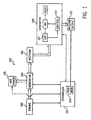
- FIG. 1 A block diagram of an engine inverter based welding power supply 100 is shown in Figure 1, where the thick black lines indicate power transmission, and the thin lines indicate control or feedback signals.
- Welding power supply 100 includes an engine 102, a generator 104, an aux power output 105, a rectifier 106, a converter 108, a controller . 110, and a welding output 112.
- engine 102 is a gas or diesel powered engine (a primary mover) that drives a shaft on which a rotor of generator 104 is mounted. Any engine suitable for the desired power output may be used, and in the preferred embodiment the engine is a commercially available diesel engine, model DH905 or DH1005, made by Kubota. This model includes a lever that is used to select between idling speed and a run (or higher) speed. As used herein run and running speed refer to a higher than idle speed.
- Generator 104 may be a typical generator having a rotor and stator, and, in the preferred embodiment, is designed by using a single phase generator such as that used in the MetroTM welding power supply available from the assignee of this invention.
- the auxiliary and welding winding of the MetroTM are replaced with three phase windings for this invention.
- the rotor is magnetically coupled with the stator, and a field current is supplied such that when the rotor is turned, an ac output current is produced.
- the electrical output of generator 104 is provided to a rectifier 106, which produces rectified dc power.
- the rectified dc power is provided to converter 108, which includes, in the preferred embodiment, at least one energy storage device such as a capacitor 107 for smoothing the ripple in the rectified signal to provide a dc bus.
- An alternative embodiment uses a dc generator instead of ac generator 104 and rectifier 111, or rectifier 111 may be part of generator 104, or between generator 104 and converter 108.
- Converter 108 also includes, in the preferred embodiment, an inverter 109 and rectifier 111 that convert the smoothed and rectified dc signal to a welding output (having an appropriate current and voltage).
- Converter 108 is in the preferred embodiment, a series resonant converter that inverts the dc bus and an output rectifier to produce a dc welding current as the welding output 112.
- An ac output is used in an alternative embodiment.
- a suitable series resonant converter is described in detail in GB-A-2309130, which is owned by the assignee of the present invention, and is hereby incorporated by reference. This converter is also available commercially, from the assignee of the present invention, as the XMT304TM power supply.
- a power control circuit 113 is included in converter 108 such that the welding current is selected by the operator, and the converter provides the desired current.
- Various control functions including a hot start and a protection system are also described therein. Modifications to the XMT304TM series resonant converter to adapt it to this invention includes removing the autolink feature and reducing the OCV command. Additional modifications are described below.
- One advantage of using the preferred power source is that it readily adaptable to use in a wide range of welding processes.
- a pulse spray process may be performed.
- Other processes include short arc, spray CV, spray CC, CC stick, CC TIG, pulse MIG, or pulse TIG (for example using a PC300TM controller).
- These process may be performed using the inventive engine driven inverter welding power supply.
- Other converters such as hard switched inverters, may also be used to implement the present invention. The specific converter or inverter selected is not important, so long as it is properly controlled to provide the desired output current.
- Converter is a switched circuit that converts an ac or dc input to a different ac or dc output.
- Inverter as used herein, is a switched circuit having a dc input and provides an ac output, or one that has an ac input and a rectifier to produce a dc signal that is then switched to produce an ac output that may.
- an inverter as used herein, may include an output rectifier to produce a dc output.
- Controller 110 is provided to control the engine in response to feedback from the welding output.
- Feedback includes a signal indicative of or responsive to an output or intermediate signal, which is provided to the controller and which control decisions are made in response thereto. Feedback is not intended to encompass the user observing the process and the user making adjustments in response to the observations.
- the feedback signal may be any welding operating parameter, such as current, voltage, frequency, power, ripple current, ripple magnitude, ripple voltage, ripple frequency, or functions thereof.
- the specific parameter fedback may be mathematically operated on as required by the control scheme.
- One alternative embodiment includes the control of the generator by controller 110, as shown by the arrow from controller 110 to generator 104.
- this control should be considered as an alternative to, or an optional addition to, the control of engine 102 by controller 110.
- the control scheme of the preferred embodiment is not intended to be limiting. Rather, the invention broadly encompasses feedback in a welding power supply to control an engine/generator.
- controller 110 includes a feedback circuit 114 that is connected to the welding studs to obtain a welding current and welding voltage feedback signal.
- the specific feedback circuit will be described in detail later.
- Feedback circuit 114 is, in an alternative embodiment, separate from controller 110. However, whether it is separate from, or part of, controller 110 is not important for the present invention. Also, controller 110 may be on the same circuit board as control circuit 113. It may be useful to make controller 110 part of control circuit 113 since they may share feedback signals.
- Controller 110 uses the feedback signal to determine the input power needed by converter 108. Then, the speed of engine 102 is adjusted to provide that needed power.
- an engine speed control is controlling the speed of the engine, which controls the power output of the generator.
- control circuit 113 causes engine 102 to operate at either an idle speed, or a run speed (close to or at full throttle).
- a solenoid may be used to move the run idle lever to the desired position.
- more than two positions (run/idle) or a continuous range of positions may be selected, based on the power needed.
- controller 110 includes using controller 110 to control at least one of a throttle position, a fuel pump, an injection timer, a fuel to air ratio, fuel consumption and ignition timing.
- the decision to operate at idle or run is made based on an integrated power in the preferred embodiment. This allows the operating speed of engine 102 to be determined from energy needed instead of instantaneous or peak power.
- converter 108 includes a "hot start” feature wherein the power draw at the start of a weld is momentarily high to aid in striking of the arc and preventing sticking of the arc. This will cause a high peak or instantaneous power draw.
- controller 110 integrates the power at welding output 112 (which is directly related to the energy drained from capacitor(s) 107). When the integrated power exceeds a threshold, based on how much energy can be drained from capacitor(s) 107, the engine is caused to operate at high speed. The engine continues to run at high speed until power being drawn is no longer above the threshold.
- the engine in the preferred embodiment, provides 4Kw of inverter output power in the idle mode.
- the converter does not output more than 4Kw of power the engine produces as much power as needed while idling.
- the inverter output power is integrated, to the extent it exceeds about 4Kw.
- the integrand exceeds a threshold, the engine is caused to run at a higher speed. The integrand is reset to zero periodically.
- FIG. 2A illustrates this control scheme. Power (at the welding studs) is plotted on the Y axis, and the X axis indicates time. The 4Kw idle output is shown with a dashed line. The graphs shows that the welding set point is below 4Kw, thus, on a long-term basis the engine can provide sufficient power while idling. However, as may be seen, the "hot start” causes the instantaneous power to exceed 4Kw. Controller 110 integrates the cross hatched area, which is the energy drain on the capacitors when the engine is idling. Figure 2B shows the integrand plotted over time. If the integrand exceeds the run threshold, then controller 110 causes engine 102 to operate at a higher speed.
- controller 110 includes circuitry to decide whether to run at idle or high speed based on the machine settings.
- controls typically on a power supply front panel
- the setting may be dialled or typed in, and controller 110 monitors one or more of these settings, and determines frcm a look-up table, microprocessor, or analog circuit whether or not the engine will need to operate at running speed, or if idling will suffice.
- the throttle lever is moved in accordance with that determination.
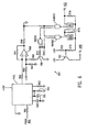
- Figure 3 is the circuit diagram of a multiplier 301 and an integrator 302 of controller 110.
- a signal V b is responsive to the welding output voltage, and is provided through a circuit including a plurality of resistors R1 (100K ohms), R2 (2K ohms), R3 (100K ohms), R4 (45K ohms), R4A (100K ohms) and R5 (3.32K ohms), a pair of op amps A1 and A2, a pair of capacitors C1 (330 ⁇ F) and C2 (47 pF), a diode D1 and a pair of transistors T1 and T2.
- the components are arranged such that the signal provided to the base of a transistor T5 is indicative of the voltage magnitude.
- a signal I fb is responsive to the welding output current, and is obtained using a LEM.
- I fb and is provided through an op amp A10, including a pair of resistors R10 (100K ohms) and R11 (1 50 ohms), and a capacitor C10 (22 Pf), a diode D10 to the collector of transistor T5.
- a feedback resistor R12 is also provided.
- Another transistor T10, a capacitor C11 (0.001 ⁇ F), a resistor R13 (10K ohms) and an op amp A11 are connected to the emitter of transistor T5 such that the output of op amp A11 is a signal indicative of and responsive to the power at the welding studs (i.e. a power feedback signal).
- the power feedback signal is provided to integrator circuit 302 which includes an op amp A15 and resistors R18 (10K ohms), R16 (562K ohms), R17 (12.1K ohms) and a feedback capacitor C18 0.1 ⁇ F).
- the output of op amp A15 is the integrated power when the power exceeds 4 Kw, and is used by controller 110 to determine when to cause the engine to operate at run speed.
- Resistors R16 (562K ohms) and R17 (12.1 K ohms) set the 4Kw level
- resistor R18 (10K ohms) and capacitor C18 (0.1 ⁇ F) provide an RC integrating time constant.
- the decision can be made by controller 110 using a simple comparator having a threshold as one input and the output of op amp A15 as the other input.
- FIG. 4 shows a voltage regulator 401 that regulates the voltage of generator 104.
- Voltage regulator 401 is part of controller 110 in the preferred embodiment, although it may be separate from controller 110.
- voltage regulator 401 controls the generator field current such that the output voltage of the generator is at a desired level.
- a rectifier/scaler 402 receives the three phase generator output voltage, and rectifies and scales it.
- a voltage command 404 receives as an input the signal indicating Whether the engine is in the run or idle mode, and provides a set point command signal to an adder 406.
- the set point command is one of two values, depending upon whether the engine is idling or running at high speed.
- Adder 406 also receives the scaled three phase voltage and its output is an error signal. The error signal is provided to a gain stage 407, and then to an adder 408.
- a frequency sensor 410 senses the frequency of the generator (which is indicative of engine speed) and provided a signal to a limiter 411 that is used by adder 408 to limit the field current.
- Frequency sensor 410 receives as another input the run/idle command, and different field current limits are set, depending on whether the engine is running at high speed or idling.
- adder 408 provides a field current command signal that is a function of the error, and is limited by the engine/generator frequency and the run/idle selection.
- the field current command signal is provided to an adder 412, which also receives a field current feedback signal.
- the output of adder 412 is the difference between the field current command and feedback, and is thus a field current error signal.
- the error signal is provided to another gain stage 41g.
- a PWM chip 416 compares the field current error signal to a threshold, and turns on and off a transistor as need. The transistor connects the 120 VAC field power to the field of generator 104.
- Rectifier/scaler 402 is shown schematically on Figure 5, and includes three identical circuits, each of which has a unique two of the three phases as inputs.
- each circuit includes nine feedback and scaling resistors (R20-50), two op amps (A20-A25), and a capacitor (C20-C22).
- the components have the following values: resistors R20, R24 and R28 are 332K ohms, resistors R21, R25 and R29 are 16. 2K ohms, resistors R22, R26 and R30 are 332K ohms, resistors R23, R27 and R31 are 16.
- resistors R33, R34 and R35 are 12.1K ohms
- resistors R36, R37 and R38 are 12.1K ohms
- resistors R41, R42 and R43 are 10K ohms
- resistors R44, R45 and R46 are 10K ohms
- resistors R48, R49 and R50 are 100K ohms
- capacitors C20, C21 and C22 are 0.01 ⁇ F.
- the output is summed and buffered by op amp A27 and resistor R47 (1 5K ohms) and capacitor C40 (0.01 ⁇ F).
- Voltage command 404 includes resistor R51 (10.8K ohms) and R52 (6.75K ohms) and a relay CR1. One of the contacts of CR1 is open, and the other closed, depending on whether idle or run is selected.
- Adder 406, gain stage 407, and adder 408 are also shown on Figure 5. They include an op amp A30, a feedback resistor R55 (3.32K ohms), a feedback capacitor C42 (1 ⁇ F), and a transistor T20. These components are configured to provide an output that is the error of the voltage command from the setpoint, limited by the frequency sense circuit 410.
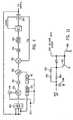
- Frequency sense circuit 410 is shown on Figure 6 and receives an input from scaler/rectifier 410. That input is provide through a resistor R61 (475K ohms) to a frequency-voltage converter chip FVC1.
- Frequency-voltage converter chip FVC1 is conventionally configured and includes associated components resistors R62 (10K ohms) and resistors R63, and capacitors C60 (0.1 ⁇ F) and C61 (1 ⁇ F).
- the output of FVC1 is provided to an op amp A60, which includes associated components resistors R64 (1K ohms), R65 (18.2K ohms), R66 (8.25 ohms), R67 (1M ohms) and R69 (2K ohms).
- the idle/run select signal is provided through a transistor T60 and resistors R70 (10K ohms) and R68 (7.5K ohms) to one input of op amp A60.
- Frequency sense circuit 410 also includes three NAND gates, NAND1, NAND2, and NAND3.
- the NAND gates, along with a pair of analog switches S60 and S61, and associated circuitry resistors R72 (20K ohms) and R73 (1.53K ohms), R75 (3.92K ohms), R76 (1.74K ohms) and transistor T61, are configured top provide the limiting signal to adder 408.
- One alternative embodiment includes using frequency sense circuit 410 or an alternative circuit to determine if the engine is slowing down to the point where a stall is likely. If controller 110 determines that a stall is likely, then the converter controller may be over-ridden such that the output is temporarily reduced, until the likelihood of a stall is reduced.
- Figure 7 is a schematic of adder 412 and gain stage 414, along with PWM chip 416.
- the field current feedback signal is scaled by an op amp A80 and resistors R8( (10K ohms), R81 (56K ohms) and R82 (10K ohms).
- Capacitor C80 is 0.01 ⁇ F.
- the output of op amp A80 is summed with the command signal from adder 408 by op amp A81 and a resistor R84 (100K ohms) to provide the error signal.
- An op amp A82, and resistors R85 (10K ohms) and R86 (10K ohms) provide the gain stage.
- the output of gain stage 414 is provided through a resistor R87 (3.32K ohms) to a PWM chip IC1 that is configured in a conventional manner to turn on and off a transistor T80 and provide a current to a field winding FW1, a pair of brushes B1 and B2, and a pair of slip rings S1 and S2, in accordance with a desired current level.
- One embodiment of the present invention includes the use of an RC delay circuit in the under voltage protection circuit that begins to charge when the under voltage switch is turned on. The capacitor continues to charge so long as the switch is on. After a sufficient delay, (1 sec ln the preferred embodiment) the under voltage lockout mechanism is activated.
- the delay circuit is shown in Figure 11 and the low voltage detect signal is provided through a diode D90 and a 1M ohm resistor R90 to charge a 1 ⁇ F capacitor C90. Then capacitor C90 is charged the low voltage protection shut off signal is provided, but a transient lasting less than the time it takes to charge capacitor C90 (1 sec) is ignored.
- Capacitor C90 is discharged rapidly through a 100K ohm resistor R92 and a diode D92, by a transistor T92.
- Transistor T92 is turned on by a 2K ohm resistor R93 when the low voltage is not detected.
- the preferred embodiment uses a 24 volt control board power for the under voltage input, which is derived from, and directly proportional to, the ac input voltage, to check for under voltage.
- the preferred embodiment includes the use of a single phase auxiliary power output, 120 VAC at 60 Hz, for power tools, lights etc. 240 VAC and/or 50 hz may also be provided.
- the auxiliary power may be taken directly from the generator, without pre-conditioning, or it may be pre-conditioned.
- a damper cage is provided, in the preferred embodiment, to counteract the unbalanced load.
- a damper cage is a series of low resistance conductors close to the surface of the rotor pole bodies.
- the damper cage acts as a low impedance winding on the rotor.
- the backward magnetic field wave from the stator currents induces large amounts of current in the damper cage bars. This current induces a magnetic field which tends to cancel the backward magnetic stator wave.
- the damper cage includes seven aluminum rods 0.25 inches in diameter placed in closed slots.
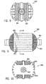
- Figures 8-10 show an end view, side view, and sectional view, respectively, of a rotor having a damper cage in accordance with the present invention.
- the rotor is mounted on a shaft 801 and includes winding 802.
- the seven aluminum bars 803 may be seen in Figures 9 and 10.
- the slots the bars are placed in are, in the preferred embodiment, 0.26 inches in diameter, and 0.03 below the surface.
- the damper cage is completed with an aluminum piece, cut to the same shape as the lamination, on each end.
- the rods are TIG welded to the end pieces.
- Alternative methods of construction include using copper rods silver soldered to copper end pieces, copper rods brazed or welded to a copper ring end piece, or aluminum die casting through the rotor holes.
- the embodiment shown is a two pole generator, but a generator with four or more poles could also be used.
- the preferred embodiment monitors the demand of the aux load, and if necessary causes the engine to run at high speed in response to the aux load.
- One alternative embodiment that also reduces distortion from the auxiliary power output is to include an aux power feedback circuit in controller 110. Another is to add a large capacitor on the leg which receives the higher voltage. Also, multiple stators may also reduce distortion caused by an unbalanced load.
- controller 110 uses the feedback to determine the desired engine speed.
- the selected speed may be one of at least two discreet speeds (idle/run e.g.) or from a continuous spectrum of speeds.
- the parameters used for feedback include one or more of inverter output and/or tank current, inverter output and/or tank voltage, inverter output and/or tank power, ripple parameters and frequency.
- the "tank" feedback signals may be particularly appropriate when the converter is a series resonator converter.
- Another alternative includes using an output transformer, and deriving the feedback signals (such as those described above) from the secondary side of the transformer).
- the feedback signa may, as described above, be a mathematical function of the operating parameter.
- Another alternative includes controlling at least one of a throttle position, a fuel pump, an injection timer, a fuel to air ratio, fuel consumption and ignition timings of the engine.
- the generator operating parameter may be field current, generator output (or inverter input) current, voltage, power, frequency, or aux current, voltage, power or frequency.
- the fedback signal may be a mathematical function of the operating parameter.
- the engine parameter being controlled may be speed, throttle position a fuel pump, an injection timer, a fuel to air ratio, fuel consumption and ignition timing.
- Another alternative is to control the generator in response to the welding and converter operating parameters described above.
- the field current is controlled in one alternative embodiment.
- Other alternatives include controlling the inverter so it operates more effectively with a generator input.
- One such alternative is described above, wherein the inverter is controlled so that it can operate at low voltages for a period of time.
- Another alternative is to provide a pre-regulator between the generator and the converter so that the input mimics ac line power.
- the preregulator may include power factor correction, a rectifier, large capacitors or energy storage devices, and a controlled bridge.
- One alternative embodiment includes a soft switched converter as the pre-regulator, and another is a voltage converter as the pre-regulator.
- the pre-regulator may be particularly useful when the aux power is derived directly from the generator.
- the aux power may be pre-regulated.
- Another alternative is using a 60Hz inverter to produce the aux power. Either single or three phase can be used as an input to the aux inverter.
Description
- The present invention relates generally to the art of welding power supplies. More specifically, it relates to inverter welding power supplies driven by an engine.
- There are different types of prior art welding power supplies. Two types of welding power supplies are phase controlled and inverter-based power supplies. Both types typically receive an ac line (60Hz) input. However, inverter power supplies can be controlled to a desired frequency, but phase controlled power supplies are limited to the input frequency. Also, phase controlled power supplies cannot be used for pulse spray processes. Inverter-based power supplies are often preferred because they are lighter, have a faster response, provide better weld characteristics, and are better suited for multiple processes (MIG, TIG, stick etc.).
- An inverter power supply receives a dc input (often called the dc bus), and switches the input to provide a pulsed or ac output. Prior art inverter welding power supplies have been designed to receive a
line frequency input 60 or 50 Hz), and to rectify that input to produce the dc bus. - The inverted ac output can be used as the welding output. However, some prior art welding power supplies include a rectifier which rectifies the ac inverter output to provide a dc welding output. The dc input to the inverter is typically obtained by rectifying an ac line input. Many inverter power supplies have controls which allow the power supply to effectively convert the ac line power into useful dc (and sometimes ac) welding power.
- Engine driven generators used in welding are also common. An engine driven welding power supply is necessary for applications where the user needs to weld at multiple locations and finds it necessary to move the welding power supply. An auxiliary power output (110 or 220 VAC) is usually provided for power tools, lights etc. Typically, engine driven generators are used to drive a simple tapped reactor or phase controlled power supplies. They often require an engine and generator specifically designed for the welding power supply, which can be more expensive than using a standard engine/generator. Phase controlled engine drive welding power supplies necessarily include all of the disadvantages of phase controlled power supplies.
- Another prior art engine driven welding power supply is a dc welding power supply, wherein the dc output of the generator is used directly for a dc welding output. Such a welding power supply, with field control, is shown in US-A-4,465,920.
- A few prior art inverter welding power supplies have been connected to a generator output and used as engine driven inverter welding power supplies. The generator ac output serves as the ac inverter input (which is rectified to create the dc bus). This arrangement creates many problems. First, inverter based welding power supplies have heretofore been designed to receive the relatively stable and constant ac line voltages. A generator does not always produce such a stable and constant output. Second, these engines usually operate at full throttle constantly, and are very inefficient.
- The common practice of providing an auxiliary power output on the generator has at least one disadvantage. The auxiliary power is single phase, 120 or 240 VAC at 50 or 60 Hz, and is used for power tools, lights etc. However, the single phase output unbalances the three phase output, and the result is harmonic distortion in all three phases. The distortion will cause one of the phases to have much higher peak voltage than the other two phases. The unusually high peak voltage may damage the inverter input capacitors, or require larger capacitors.
- The distortion is caused by a backward component of a magnetic field wave. Then a three phase load is present the three stator currents produce a magnetic field wave that rotates in the same direction as, and at the same speed as, the rotor. Thus, there is no relative motion between the rotor and the magnetic field wave, and the magnetic field wave does not induce any voltage in the rotor. However, when the load is unbalanced the magnetic field wave created by the stator currents does not move at the speed as and in the same direction as the rotor. The magnetic field produced by the stator currents when an unbalanced load is present may be resolved into two components: a forward component that is in the same direction and at the same speed as the rotor, and a backward component. The forward component behaves as a balanced three phase load, and does not cause a problem. The backward component is moving at the same speed as the rotor, but in the opposite direction. Thus, it has a motion relative to the rotor of twice the generator speed. This "moving" magnetic field will induce voltage in the rotor field winding, which causes the high output voltage. Damper cages have been used in generators (although not necessarily in the welding art) to counter-act or compensate for the effect of unbalanced loads.
- According to a first aspect of the invention a method of providing welding power comprises a method of providing welding power comprises:
- generating an electrical output with an engine and generator;
- inverting the electrical output to provide an ac inverter output; and
- controlling the engine using feedback indicative of a welding output operating parameter.
-
- According to a second aspect of this invention a stand alone welding power supply comprises a stand alone welding power supply comprises:
- a primary mover mechanically coupled to a rotating shaft;
- a generator having a rotor mechanically coupled to the shaft, and further having a stator magnetically coupled to the rotor, whereby the generator provides a generator output;
- an inverter having an inverter input in electrical communication with the generator output, wherein the inverter inverts power from the inverter input to provide an inverter output;
- a controller coupled to the primary mover to control it and having a feedback input; and
- a feedback circuit coupled to the welding output and the feedback input for providing a feedback signal responsive to at least one welding output operating parameter to the feedback input.
-
- Preferably a speed control is provided for the primary mover and the controller includes an output coupled to the speed control, wherein the speed of the primary mover is controlled in response to the feedback signal. One embodiment provides for selecting between an idle and run speed in response to the feedback signal. Alternatives include controlling one or more of a throttle position, a fuel pump, an injection timer, a fuel to air ratio, fuel consumption and ignition timing.
- Other aspects of the invention include deriving the feedback from welding current, welding voltage, welding power, ripple current, ripple power, ripple voltage and/or functions thereof. The power and a function thereof may be obtained from a circuit that multiplies signals representative of voltage and current to obtain a signal representative of power, and a circuit that integrates the signal representative of power.
- Preferably the power supply includes one or more input energy storage devices that store energy after rectification and the controller causes the engine to increase speed when the energy stored decreases past a threshold.
- A particular embodiment of a power supply in accordance with this invention will now be described with reference to the accompanying drawings, in which:-
- Figure 1 is 2 block diagram of the embodiment of the present invention;
- Figures 2A and 2B are graphs showing power and integrated power;
- Figure 3 is a schematic of part of a controller for controlling engine speed;
- Figure 4 is a control diagram for a generator field current controller;
- Figures 5-7 are circuit diagrams which implement the control diagram of Figure 4;
- Figure 8 is an end view of a damper cage;
- Figure 9 is a side end view of the damper cage of Figure 8;
- Figure 10 is a sectional view of the damper cage of Figure 8, taken along lines 10-10; and
- Figure 11 is a circuit diagram of a delay circuit used in the embodiment.
-
- This invention relates to a stand-alone welding power supply. As used herein, stand alone means a welding power supply that includes a generator, rather than a welding power supply which derives power from the ac line power line. In other words, a stand alone welding power supply produces power, rather than converts ac line power. Also, a stand alone welding power supply may have the mechanical and electrical portions in a single case, it may be modular, or the engine, generator and electrical power supply may each be separate.
- A block diagram of an engine inverter based
welding power supply 100 is shown in Figure 1, where the thick black lines indicate power transmission, and the thin lines indicate control or feedback signals. Weldingpower supply 100 includes anengine 102, agenerator 104, anaux power output 105, arectifier 106, aconverter 108, a controller . 110, and awelding output 112. Generally speaking,engine 102 is a gas or diesel powered engine (a primary mover) that drives a shaft on which a rotor ofgenerator 104 is mounted. Any engine suitable for the desired power output may be used, and in the preferred embodiment the engine is a commercially available diesel engine, model DH905 or DH1005, made by Kubota. This model includes a lever that is used to select between idling speed and a run (or higher) speed. As used herein run and running speed refer to a higher than idle speed. -
Generator 104 may be a typical generator having a rotor and stator, and, in the preferred embodiment, is designed by using a single phase generator such as that used in the Metro™ welding power supply available from the assignee of this invention. The auxiliary and welding winding of the Metro™ are replaced with three phase windings for this invention. The rotor is magnetically coupled with the stator, and a field current is supplied such that when the rotor is turned, an ac output current is produced. - The electrical output of
generator 104 is provided to arectifier 106, which produces rectified dc power. The rectified dc power is provided toconverter 108, which includes, in the preferred embodiment, at least one energy storage device such as acapacitor 107 for smoothing the ripple in the rectified signal to provide a dc bus. An alternative embodiment uses a dc generator instead ofac generator 104 and rectifier 111, or rectifier 111 may be part ofgenerator 104, or betweengenerator 104 andconverter 108. -
Converter 108 also includes, in the preferred embodiment, an inverter 109 and rectifier 111 that convert the smoothed and rectified dc signal to a welding output (having an appropriate current and voltage).Converter 108 is in the preferred embodiment, a series resonant converter that inverts the dc bus and an output rectifier to produce a dc welding current as thewelding output 112. An ac output is used in an alternative embodiment. A suitable series resonant converter is described in detail in GB-A-2309130, which is owned by the assignee of the present invention, and is hereby incorporated by reference. This converter is also available commercially, from the assignee of the present invention, as the XMT304™ power supply. As described in GB-A-2309130 apower control circuit 113 is included inconverter 108 such that the welding current is selected by the operator, and the converter provides the desired current. Various control functions including a hot start and a protection system are also described therein. Modifications to the XMT304™ series resonant converter to adapt it to this invention includes removing the autolink feature and reducing the OCV command. Additional modifications are described below. - One advantage of using the preferred power source is that it readily adaptable to use in a wide range of welding processes. For example, by including an Optima™ or 60M™ controller, each available from the present assignee, a pulse spray process may be performed. Other processes include short arc, spray CV, spray CC, CC stick, CC TIG, pulse MIG, or pulse TIG (for example using a PC300™ controller). These process may be performed using the inventive engine driven inverter welding power supply. Other converters, such as hard switched inverters, may also be used to implement the present invention. The specific converter or inverter selected is not important, so long as it is properly controlled to provide the desired output current. Converter, as used herein, is a switched circuit that converts an ac or dc input to a different ac or dc output. Inverter, as used herein, is a switched circuit having a dc input and provides an ac output, or one that has an ac input and a rectifier to produce a dc signal that is then switched to produce an ac output that may. Also, an inverter, as used herein, may include an output rectifier to produce a dc output.
-
Controller 110 is provided to control the engine in response to feedback from the welding output. Feedback, as used herein, includes a signal indicative of or responsive to an output or intermediate signal, which is provided to the controller and which control decisions are made in response thereto. Feedback is not intended to encompass the user observing the process and the user making adjustments in response to the observations. The feedback signal may be any welding operating parameter, such as current, voltage, frequency, power, ripple current, ripple magnitude, ripple voltage, ripple frequency, or functions thereof. The specific parameter fedback may be mathematically operated on as required by the control scheme. - One alternative embodiment includes the control of the generator by
controller 110, as shown by the arrow fromcontroller 110 togenerator 104. However, this control should be considered as an alternative to, or an optional addition to, the control ofengine 102 bycontroller 110. Also, the control scheme of the preferred embodiment is not intended to be limiting. Rather, the invention broadly encompasses feedback in a welding power supply to control an engine/generator. - Specifically, in the preferred embodiment,
controller 110 includes afeedback circuit 114 that is connected to the welding studs to obtain a welding current and welding voltage feedback signal. The specific feedback circuit will be described in detail later.Feedback circuit 114 is, in an alternative embodiment, separate fromcontroller 110. However, whether it is separate from, or part of,controller 110 is not important for the present invention. Also,controller 110 may be on the same circuit board ascontrol circuit 113. It may be useful to makecontroller 110 part ofcontrol circuit 113 since they may share feedback signals. -
Controller 110 uses the feedback signal to determine the input power needed byconverter 108. Then, the speed ofengine 102 is adjusted to provide that needed power. Generally, an engine speed control is controlling the speed of the engine, which controls the power output of the generator. Specifically, in the preferred embodiment,control circuit 113 causesengine 102 to operate at either an idle speed, or a run speed (close to or at full throttle). A solenoid may be used to move the run idle lever to the desired position. Alternatively, more than two positions (run/idle) or a continuous range of positions may be selected, based on the power needed. One alternative embodiment includes usingcontroller 110 to control at least one of a throttle position, a fuel pump, an injection timer, a fuel to air ratio, fuel consumption and ignition timing. - The decision to operate at idle or run is made based on an integrated power in the preferred embodiment. This allows the operating speed of
engine 102 to be determined from energy needed instead of instantaneous or peak power. - More specifically, as stated above,
converter 108 includes a "hot start" feature wherein the power draw at the start of a weld is momentarily high to aid in striking of the arc and preventing sticking of the arc. This will cause a high peak or instantaneous power draw. However, the total energy used in such a hot start is not of a sufficient magnitude to decrease the energy stored by capacitor(s) 107 to a level at which the inverter will not operate properly. Thus,controller 110 integrates the power at welding output 112 (which is directly related to the energy drained from capacitor(s) 107). When the integrated power exceeds a threshold, based on how much energy can be drained from capacitor(s) 107, the engine is caused to operate at high speed. The engine continues to run at high speed until power being drawn is no longer above the threshold. - The engine, in the preferred embodiment, provides 4Kw of inverter output power in the idle mode. Thus, so long as the converter does not output more than 4Kw of power the engine produces as much power as needed while idling. If more than 4Kw of power is output by
converter 108 for a short period of time (such as during the hot start) the engine does not need to speed up. Thus, the inverter output power is integrated, to the extent it exceeds about 4Kw. When the integrand exceeds a threshold, the engine is caused to run at a higher speed. The integrand is reset to zero periodically. - Figure 2A illustrates this control scheme. Power (at the welding studs) is plotted on the Y axis, and the X axis indicates time. The 4Kw idle output is shown with a dashed line. The graphs shows that the welding set point is below 4Kw, thus, on a long-term basis the engine can provide sufficient power while idling. However, as may be seen, the "hot start" causes the instantaneous power to exceed 4Kw.
Controller 110 integrates the cross hatched area, which is the energy drain on the capacitors when the engine is idling. Figure 2B shows the integrand plotted over time. If the integrand exceeds the run threshold, thencontroller 110 causesengine 102 to operate at a higher speed. - One alternative embodiment of
controller 110 includes circuitry to decide whether to run at idle or high speed based on the machine settings. When an operator is going to weld, they set controls (typically on a power supply front panel) indicating the welding parameters, such as current, process, voltage, etc. The setting may be dialled or typed in, andcontroller 110 monitors one or more of these settings, and determines frcm a look-up table, microprocessor, or analog circuit whether or not the engine will need to operate at running speed, or if idling will suffice. The throttle lever is moved in accordance with that determination. - Figure 3 is the circuit diagram of a
multiplier 301 and anintegrator 302 ofcontroller 110. A signal V b is responsive to the welding output voltage, and is provided through a circuit including a plurality of resistors R1 (100K ohms), R2 (2K ohms), R3 (100K ohms), R4 (45K ohms), R4A (100K ohms) and R5 (3.32K ohms), a pair of op amps A1 and A2, a pair of capacitors C1 (330 µF) and C2 (47 pF), a diode D1 and a pair of transistors T1 and T2. The components are arranged such that the signal provided to the base of a transistor T5 is indicative of the voltage magnitude. - A signal Ifb is responsive to the welding output current, and is obtained using a LEM. Ifb and is provided through an op amp A10, including a pair of resistors R10 (100K ohms) and R11 (1 50 ohms), and a capacitor C10 (22 Pf), a diode D10 to the collector of transistor T5. A feedback resistor R12 is also provided. Another transistor T10, a capacitor C11 (0.001 µF), a resistor R13 (10K ohms) and an op amp A11 are connected to the emitter of transistor T5 such that the output of op amp A11 is a signal indicative of and responsive to the power at the welding studs (i.e. a power feedback signal).
- The power feedback signal is provided to
integrator circuit 302 which includes an op amp A15 and resistors R18 (10K ohms), R16 (562K ohms), R17 (12.1K ohms) and a feedback capacitor C18 0.1 µF). The output of op amp A15 is the integrated power when the power exceeds 4 Kw, and is used bycontroller 110 to determine when to cause the engine to operate at run speed. Resistors R16 (562K ohms) and R17 (12.1 K ohms) set the 4Kw level, and resistor R18 (10K ohms) and capacitor C18 (0.1 µF) provide an RC integrating time constant. The decision can be made bycontroller 110 using a simple comparator having a threshold as one input and the output of op amp A15 as the other input. - Figure 4 shows a voltage regulator 401 that regulates the voltage of
generator 104. Voltage regulator 401 is part ofcontroller 110 in the preferred embodiment, although it may be separate fromcontroller 110. Generally, voltage regulator 401 controls the generator field current such that the output voltage of the generator is at a desired level. - Specifically, a rectifier/
scaler 402 receives the three phase generator output voltage, and rectifies and scales it. Avoltage command 404 receives as an input the signal indicating Whether the engine is in the run or idle mode, and provides a set point command signal to anadder 406. Thus, the set point command is one of two values, depending upon whether the engine is idling or running at high speed.Adder 406 also receives the scaled three phase voltage and its output is an error signal. The error signal is provided to again stage 407, and then to anadder 408. - A
frequency sensor 410 senses the frequency of the generator (which is indicative of engine speed) and provided a signal to alimiter 411 that is used byadder 408 to limit the field current.Frequency sensor 410 receives as another input the run/idle command, and different field current limits are set, depending on whether the engine is running at high speed or idling. Thus,adder 408 provides a field current command signal that is a function of the error, and is limited by the engine/generator frequency and the run/idle selection. - The field current command signal is provided to an
adder 412, which also receives a field current feedback signal. The output ofadder 412 is the difference between the field current command and feedback, and is thus a field current error signal. The error signal is provided to another gain stage 41g. APWM chip 416 compares the field current error signal to a threshold, and turns on and off a transistor as need. The transistor connects the 120 VAC field power to the field ofgenerator 104. - A circuit which implements this scheme is shown in Figures 5-7. Rectifier/
scaler 402 is shown schematically on Figure 5, and includes three identical circuits, each of which has a unique two of the three phases as inputs. Generally, each circuit includes nine feedback and scaling resistors (R20-50), two op amps (A20-A25), and a capacitor (C20-C22). The components have the following values: resistors R20, R24 and R28 are 332K ohms, resistors R21, R25 and R29 are 16. 2K ohms, resistors R22, R26 and R30 are 332K ohms, resistors R23, R27 and R31 are 16. 2K ohms, resistors R33, R34 and R35 are 12.1K ohms, resistors R36, R37 and R38 are 12.1K ohms, resistors R41, R42 and R43 are 10K ohms, resistors R44, R45 and R46 are 10K ohms, resistors R48, R49 and R50 are 100K ohms and capacitors C20, C21 and C22 are 0.01 µF. The output is summed and buffered by op amp A27 and resistor R47 (1 5K ohms) and capacitor C40 (0.01 µF). -
Voltage command 404 includes resistor R51 (10.8K ohms) and R52 (6.75K ohms) and a relay CR1. One of the contacts of CR1 is open, and the other closed, depending on whether idle or run is selected. -
Adder 406, gainstage 407, andadder 408 are also shown on Figure 5. They include an op amp A30, a feedback resistor R55 (3.32K ohms), a feedback capacitor C42 (1 µF), and a transistor T20. These components are configured to provide an output that is the error of the voltage command from the setpoint, limited by thefrequency sense circuit 410. -
Frequency sense circuit 410 is shown on Figure 6 and receives an input from scaler/rectifier 410. That input is provide through a resistor R61 (475K ohms) to a frequency-voltage converter chip FVC1. Frequency-voltage converter chip FVC1 is conventionally configured and includes associated components resistors R62 (10K ohms) and resistors R63, and capacitors C60 (0.1 µF) and C61 (1 µF). The output of FVC1 is provided to an op amp A60, which includes associated components resistors R64 (1K ohms), R65 (18.2K ohms), R66 (8.25 ohms), R67 (1M ohms) and R69 (2K ohms). The idle/run select signal is provided through a transistor T60 and resistors R70 (10K ohms) and R68 (7.5K ohms) to one input of op amp A60. -
Frequency sense circuit 410 also includes three NAND gates, NAND1, NAND2, and NAND3. The NAND gates, along with a pair of analog switches S60 and S61, and associated circuitry resistors R72 (20K ohms) and R73 (1.53K ohms), R75 (3.92K ohms), R76 (1.74K ohms) and transistor T61, are configured top provide the limiting signal to adder 408. One alternative embodiment includes usingfrequency sense circuit 410 or an alternative circuit to determine if the engine is slowing down to the point where a stall is likely. Ifcontroller 110 determines that a stall is likely, then the converter controller may be over-ridden such that the output is temporarily reduced, until the likelihood of a stall is reduced. - Figure 7 is a schematic of
adder 412 and gainstage 414, along withPWM chip 416. The field current feedback signal is scaled by an op amp A80 and resistors R8( (10K ohms), R81 (56K ohms) and R82 (10K ohms). Capacitor C80 is 0.01 µF. The output of op amp A80 is summed with the command signal fromadder 408 by op amp A81 and a resistor R84 (100K ohms) to provide the error signal. An op amp A82, and resistors R85 (10K ohms) and R86 (10K ohms) provide the gain stage. The output ofgain stage 414 is provided through a resistor R87 (3.32K ohms) to a PWM chip IC1 that is configured in a conventional manner to turn on and off a transistor T80 and provide a current to a field winding FW1, a pair of brushes B1 and B2, and a pair of slip rings S1 and S2, in accordance with a desired current level. - Many welding power supplies that operate on an ac power line include an under voltage protection circuit. thus, when the input voltage drops below a threshold a switch is turned on (or off) such that and the power supply controller shuts down the power supply. However, if the load of an engine driven welding power supply increases when the engine is idling, a transient voltage dip occurs. Thus, if the converter controller includes an under voltage protection circuit, it must be removed or modified to accommodate the relatively slow response of the engine.
- One embodiment of the present invention includes the use of an RC delay circuit in the under voltage protection circuit that begins to charge when the under voltage switch is turned on. The capacitor continues to charge so long as the switch is on. After a sufficient delay, (1 sec ln the preferred embodiment) the under voltage lockout mechanism is activated. The delay circuit is shown in Figure 11 and the low voltage detect signal is provided through a diode D90 and a 1M ohm resistor R90 to charge a 1 µF capacitor C90. Then capacitor C90 is charged the low voltage protection shut off signal is provided, but a transient lasting less than the time it takes to charge capacitor C90 (1 sec) is ignored. Capacitor C90 is discharged rapidly through a 100K ohm resistor R92 and a diode D92, by a transistor T92. Transistor T92 is turned on by a 2K ohm resistor R93 when the low voltage is not detected. The preferred embodiment uses a 24 volt control board power for the under voltage input, which is derived from, and directly proportional to, the ac input voltage, to check for under voltage.
- The preferred embodiment includes the use of a single phase auxiliary power output, 120 VAC at 60 Hz, for power tools, lights etc. 240 VAC and/or 50 hz may also be provided. The auxiliary power may be taken directly from the generator, without pre-conditioning, or it may be pre-conditioned. A damper cage is provided, in the preferred embodiment, to counteract the unbalanced load. Generally, a damper cage is a series of low resistance conductors close to the surface of the rotor pole bodies. The damper cage acts as a low impedance winding on the rotor. The backward magnetic field wave from the stator currents (caused by the single phase load) induces large amounts of current in the damper cage bars. This current induces a magnetic field which tends to cancel the backward magnetic stator wave.
- Specifically, in the preferred embodiment, the damper cage includes seven aluminum rods 0.25 inches in diameter placed in closed slots. Figures 8-10 show an end view, side view, and sectional view, respectively, of a rotor having a damper cage in accordance with the present invention. The rotor is mounted on a
shaft 801 and includes winding 802. The sevenaluminum bars 803 may be seen in Figures 9 and 10. The slots the bars are placed in are, in the preferred embodiment, 0.26 inches in diameter, and 0.03 below the surface. The damper cage is completed with an aluminum piece, cut to the same shape as the lamination, on each end. The rods are TIG welded to the end pieces. Alternative methods of construction include using copper rods silver soldered to copper end pieces, copper rods brazed or welded to a copper ring end piece, or aluminum die casting through the rotor holes. The embodiment shown is a two pole generator, but a generator with four or more poles could also be used. - The preferred embodiment monitors the demand of the aux load, and if necessary causes the engine to run at high speed in response to the aux load. One alternative embodiment that also reduces distortion from the auxiliary power output is to include an aux power feedback circuit in
controller 110. Another is to add a large capacitor on the leg which receives the higher voltage. Also, multiple stators may also reduce distortion caused by an unbalanced load. - One alternative embodiment is shown by the dashed control lines in Figure 1 between
controller 110 andconverter 108. The feedback signal is obtained from the inverter, rather than the welding output in this embodiment.Controller 110 uses the feedback to determine the desired engine speed. The selected speed may be one of at least two discreet speeds (idle/run e.g.) or from a continuous spectrum of speeds. The parameters used for feedback include one or more of inverter output and/or tank current, inverter output and/or tank voltage, inverter output and/or tank power, ripple parameters and frequency. The "tank" feedback signals may be particularly appropriate when the converter is a series resonator converter. Another alternative includes using an output transformer, and deriving the feedback signals (such as those described above) from the secondary side of the transformer). The feedback signa may, as described above, be a mathematical function of the operating parameter. Another alternative includes controlling at least one of a throttle position, a fuel pump, an injection timer, a fuel to air ratio, fuel consumption and ignition timings of the engine. - Other alternatives include controlling the engine based on a generator operating paraMeter feedback. The generator operating parameter may be field current, generator output (or inverter input) current, voltage, power, frequency, or aux current, voltage, power or frequency. As described above, the fedback signal may be a mathematical function of the operating parameter. Also as described above, the engine parameter being controlled may be speed, throttle position a fuel pump, an injection timer, a fuel to air ratio, fuel consumption and ignition timing.
- Another alternative is to control the generator in response to the welding and converter operating parameters described above. The field current is controlled in one alternative embodiment.
- Other alternatives include controlling the inverter so it operates more effectively with a generator input. One such alternative is described above, wherein the inverter is controlled so that it can operate at low voltages for a period of time. Another alternative is to provide a pre-regulator between the generator and the converter so that the input mimics ac line power. The preregulator may include power factor correction, a rectifier, large capacitors or energy storage devices, and a controlled bridge. One alternative embodiment includes a soft switched converter as the pre-regulator, and another is a voltage converter as the pre-regulator. The pre-regulator may be particularly useful when the aux power is derived directly from the generator. Alternatively, the aux power may be pre-regulated. Another alternative is using a 60Hz inverter to produce the aux power. Either single or three phase can be used as an input to the aux inverter.
Claims (11)
- A stand alone welding power supply comprising:an internal combustion engine primary mover (102) mechanically coupled to a rotating shaft;a generator (104) having a rotor mechanically coupled to the shaft, and further having a stator magnetically coupled to the rotor, whereby the generator (104) provides a generator output;an inverter (108) having an inverter input in electrical communication with the generator output, wherein the inverter inverts power from the inverter input to provide an inverter output;a controller (110) coupled to the primary mover (102) to control it and having a feedback input; anda feedback circuit (114) coupled to the welding output (112) and the feedback input for providing a feedback signal responsive to at least one welding output operating parameter to the feedback input.
- A power supply according to claim 1, wherein the primary mover (102) includes a speed control and the controller (110) includes an output coupled to the speed control, and wherein the speed of the primary mover (102) is controlled in response to the feedback signal.
- A power supply according to claim 2, wherein the speed control includes an idle/run selector for selecting between an idle speed and a run speed in response to the feedback signal.
- A power supply according to claim 2 or 3, further including a rectifier (106) that couples the inverter (18) to the generation output, wherein the inverter includes at least one input energy storage device that stores rectified energy and wherein the controller (110) causes the primary mover (102) to increase speed when the stored energy decreases past a threshold.
- A power supply according to any of the preceding claims, wherein the controller (110) includes means for controlling at least one of a throttle position, a fuel pump, an injection timer, a fuel-to-air ratio, fuel consumption and ignition timing of the primary mover (102).
- A power supply according to any one of the preceding claims, wherein the at least one operating parameter is welding current and/or welding voltage.
- A power supply according to claim 6, wherein the feedback circuit (114) includes a multiplier, wherein the multiplier multiplies signals representative of voltage and current to obtain a signal representative of power, and further wherein the feedback circuit (114) includes an integrator to integrate the signal representative of power.
- A power supply according to any one of the preceding claims, wherein a welding operating parameter is a function of a ripple in the output.
- A power supply according to any one of the preceding claims, further including a rectifier coupled to the inverter output to provide a dc welding output.
- A power supply according to any one of the preceding claims, wherein the generator (104) is a dc generator, or an ac dc generator, and the inverter incudes an input rectifier.
- A method of providing welding power comprising:generating an electrical output with an internal combustion engine (102) and generator (104);inverting the electrical output to provide an ac inverter output; andcontrolling the engine (102) using feedback indicative of a welding output operating parameter.
Applications Claiming Priority (2)
| Application Number | Priority Date | Filing Date | Title |
|---|---|---|---|
| US858129 | 1997-05-19 | ||
| US08/858,129 US5968385A (en) | 1997-05-19 | 1997-05-19 | Engine driven inverter welding power supply |
Publications (2)
| Publication Number | Publication Date |
|---|---|
| EP0879665A1 EP0879665A1 (en) | 1998-11-25 |
| EP0879665B1 true EP0879665B1 (en) | 2003-02-12 |
Family
ID=25327557
Family Applications (1)
| Application Number | Title | Priority Date | Filing Date |
|---|---|---|---|
| EP98303877A Expired - Lifetime EP0879665B1 (en) | 1997-05-19 | 1998-05-15 | Welding power supply |
Country Status (6)
| Country | Link |
|---|---|
| US (8) | US5968385A (en) |
| EP (1) | EP0879665B1 (en) |
| JP (1) | JP4920811B2 (en) |
| AU (1) | AU714274B2 (en) |
| CA (1) | CA2236938C (en) |
| DE (1) | DE69811287T2 (en) |
Cited By (1)
| Publication number | Priority date | Publication date | Assignee | Title |
|---|---|---|---|---|
| CN102500874A (en) * | 2011-11-10 | 2012-06-20 | 山东大学 | Intelligent magnetic biasing detection and processing device for inversion welding power supply |
Families Citing this family (62)
| Publication number | Priority date | Publication date | Assignee | Title |
|---|---|---|---|---|
| US5968385A (en) | 1997-05-19 | 1999-10-19 | Illinois Tool Works Inc. | Engine driven inverter welding power supply |
| AU757301B2 (en) * | 1997-07-23 | 2003-02-13 | Deon John Du Plessis | An electrical power generation unit |
| US6121691A (en) * | 1999-02-26 | 2000-09-19 | Illinois Tool Works Inc. | Power reduction circuit for engine acceleration |
| US6348671B1 (en) | 1999-09-23 | 2002-02-19 | Illinois Tool Works Inc. | Welder with engine power and utility power input |
| US6166349A (en) * | 1999-10-05 | 2000-12-26 | Illinois Tool Works Inc. | Hydraulically driven welding machine with feedback |
| US6489591B1 (en) * | 2000-04-10 | 2002-12-03 | Illinois Tool Works Inc. | Cooling air circuits for welding machine |
| JP2002103052A (en) * | 2000-09-27 | 2002-04-09 | Miyachi Technos Corp | Joining apparatus |
| DE10162214B4 (en) * | 2000-12-19 | 2014-02-13 | Denso Corporation | Motor vehicle engine / generator unit with synchronous machine |
| US6876096B2 (en) * | 2001-02-20 | 2005-04-05 | Deon John Du Plessis | Electrical power generation unit |
| US6531685B2 (en) | 2001-03-28 | 2003-03-11 | Illinois Tool Works Inc. | Separate exciter windings for weld and auxiliary power |
| US20020167174A1 (en) * | 2001-05-09 | 2002-11-14 | Haass Michael A. | Portable generator for commucications systems |
| US6603097B2 (en) | 2001-06-15 | 2003-08-05 | Illinois Tool Works, Inc. | Method and apparatus for controlling engine speed of a welding generator |
| US7042110B2 (en) * | 2003-05-07 | 2006-05-09 | Clipper Windpower Technology, Inc. | Variable speed distributed drive train wind turbine system |
| JP2005057900A (en) * | 2003-08-05 | 2005-03-03 | Kokusan Denki Co Ltd | Inverter generator driven by engine |
| EP1676023B1 (en) * | 2003-10-06 | 2018-04-04 | PowerSys, LLC | Power generation systems and methods of generating power |
| US7211764B2 (en) * | 2004-06-01 | 2007-05-01 | Illinois Tool Works Inc. | Engine driven welder/generator with high power accessory output operable at lower engine speeds |
| US7297899B2 (en) * | 2004-06-01 | 2007-11-20 | Illinois Tool Works Inc. | Operating parameter dependent variable output welding-type apparatus |
| US7858904B2 (en) * | 2005-01-20 | 2010-12-28 | Illinois Tool Works Inc. | System and method of controlling auxiliary/weld power outputs of a welding-type apparatus |
| US7202639B2 (en) * | 2005-04-26 | 2007-04-10 | Remy International, Inc. | Apparatus for determining wear in the frictional components of an alternator |
| FR2892574A1 (en) * | 2005-10-20 | 2007-04-27 | Leroy Somer Moteurs | DEVICE FOR CONTROLLING AN ELECTROGEN GROUP |
| US9981334B2 (en) * | 2006-09-21 | 2018-05-29 | Illinois Tool Works Inc. | Dual power integrated MIG welder and generator system |
| US20080308540A1 (en) * | 2007-06-15 | 2008-12-18 | Toru Hiroi | Engine driven welding machine |
| US8987638B2 (en) * | 2007-06-15 | 2015-03-24 | Denyo Kabushiki Kaisha | Engine driven welding machine |
| US20080314885A1 (en) * | 2007-06-21 | 2008-12-25 | Richard Hutchison | System and Method for Battery-Assisted, Engine-Driven Welding-Type Process |
| US8969762B2 (en) | 2007-07-06 | 2015-03-03 | Illinois Tool Works Inc. | Welder with intelligent battery charger |
| WO2009050182A2 (en) | 2007-10-17 | 2009-04-23 | Inventio Ag | Elevator having a suspension |
| US7834509B2 (en) * | 2008-02-28 | 2010-11-16 | Hamilton Sundstrand Corporation | Rotor assembly for electromechanical machine |
| US20090234533A1 (en) * | 2008-03-12 | 2009-09-17 | Illinois Tool Works Inc. | Programmed engine oil change notification system for an engine-driven welder/generator |
| US8115328B2 (en) * | 2009-01-30 | 2012-02-14 | Illinois Tool Works Inc. | Weld setting based engine-driven generator control system and method |
| US9796037B2 (en) * | 2009-01-30 | 2017-10-24 | Illinois Tool Works Inc. | Integrated engine-driven generator control system |
| US8125094B2 (en) * | 2009-01-30 | 2012-02-28 | Illinois Tool Works Inc. | Engine-driven generator speed control system and method |
| US8466700B2 (en) * | 2009-03-18 | 2013-06-18 | Infineon Technologies Ag | System that measures characteristics of output signal |
| US8502115B2 (en) * | 2009-06-11 | 2013-08-06 | Illinois Tool Works Inc. | Engine driven welder-generator with chopper circuit |
| CN101607338B (en) * | 2009-07-20 | 2012-05-02 | 重庆运达科技有限公司 | Starting system of diesel engine generator combined inverse system |
| US8461483B2 (en) * | 2009-07-24 | 2013-06-11 | Lincoln Global, Inc. | Engine driven welding power supplies with two piece shaft |
| US8426772B2 (en) * | 2009-09-02 | 2013-04-23 | Lincoln Global, Inc. | Auxiliary power supply for a welding machine |
| SE534501C2 (en) * | 2009-09-22 | 2011-09-13 | Safetrack Infrasystems Sisab Ab | Method and device for stick soldering |
| US9186743B2 (en) * | 2009-11-16 | 2015-11-17 | Illinois Tool Works Inc. | Welding and gouging systems with multiple power settings |
| US9421632B2 (en) | 2009-12-29 | 2016-08-23 | Lincoln Global, Inc. | Multi-output engine welder supplying full electrical power capacity to a single welding output |
| IT1400343B1 (en) * | 2010-05-27 | 2013-05-24 | Idm Srl | GENERATOR SET, PARTICULARLY FOR BATTERY CHARGER. |
| US10773327B2 (en) * | 2010-06-17 | 2020-09-15 | Illinois Tool Works Inc. | System and method for limiting welding output and ancillary features |
| US8746382B2 (en) * | 2010-12-23 | 2014-06-10 | Caterpillar Inc. | Switched reluctance generator priming strategy |
| US20120211472A1 (en) * | 2011-02-22 | 2012-08-23 | Lincoln Global, Inc. | Welding system with rotational speed converter for auxiliary power generator |
| CN103650329A (en) * | 2011-06-27 | 2014-03-19 | 开利公司 | Permanent magnet generator voltage regulation |
| US9457417B2 (en) * | 2012-03-14 | 2016-10-04 | Illinois Tool Works Inc. | Single electronic governor for multiple engines |
| US11179794B2 (en) * | 2012-06-29 | 2021-11-23 | Illinois Tool Works Inc | Welding system utilizing a distributed power bus |
| US9455604B2 (en) | 2012-10-16 | 2016-09-27 | Hamilton Sundstrand Corporation | Wound-field synchronous machine including rotor damper-sleeve |
| US10144083B2 (en) | 2013-02-22 | 2018-12-04 | Illinois Tool Works Inc. | Multi-operator engine driven welder system |
| DE102014200266A1 (en) * | 2013-09-13 | 2015-03-19 | Robert Bosch Gmbh | Arrangement for the operation of a welding system |
| CN103722322B (en) * | 2014-01-06 | 2015-07-08 | 山东大学 | Digital realization circuit and method of primary current feedback mode |
| US10124435B2 (en) * | 2014-02-24 | 2018-11-13 | Lincoln Global, Inc. | Automatic control on auxiliary voltage for engine driven welder |
| US9925613B2 (en) | 2014-03-28 | 2018-03-27 | Hobart Brothers Company | Inverter-based generator and welding system |
| US20160072420A1 (en) * | 2014-09-10 | 2016-03-10 | Briggs & Stratton Corporation | Generator with power output during engine idle |
| US10601353B2 (en) | 2016-04-29 | 2020-03-24 | Illinois Tool Works Inc. | Systems and methods to control auxiliary power output voltage using a welding output voltage |
| US10071435B2 (en) | 2016-05-13 | 2018-09-11 | Lincoln Global, Inc. | Welder-generator with start-stop |
| US10384290B2 (en) | 2016-08-15 | 2019-08-20 | Illinois Tool Works Inc. | Engine driven power supplies with output reduction |
| US10751827B2 (en) * | 2016-08-24 | 2020-08-25 | Illinois Tool Works Inc. | Variable speed engine driven generator for providing welding and auxiliary power |
| US20190061071A1 (en) * | 2017-08-28 | 2019-02-28 | Illinois Tool Works Inc. | Methods and systems for engine idling without a battery |
| US11253942B2 (en) * | 2017-09-08 | 2022-02-22 | Illinois Tool Works Inc. | Methods and apparatus for automatic control of a welding-type power supply |
| US11038437B2 (en) | 2018-05-25 | 2021-06-15 | Illinois Tool Works | AC inverter with active neutral balance |
| US11839939B2 (en) * | 2018-09-27 | 2023-12-12 | Illinois Tool Works Inc. | Systems, methods, and apparatus for pre-regulator control in welding-type power supplies |
| US11591976B2 (en) * | 2021-05-19 | 2023-02-28 | Illinois Tool Works Inc. | Methods and systems for a turbo gas engine driven welder |
Family Cites Families (47)
| Publication number | Priority date | Publication date | Assignee | Title |
|---|---|---|---|---|
| US2458658A (en) * | 1944-04-20 | 1949-01-11 | Air Reduction | Electric arc welding |
| US2804553A (en) * | 1955-10-05 | 1957-08-27 | William E Mcfarland | Idling device featuring actuatorcontrolled spring |
| FR1226873A (en) * | 1958-06-10 | 1960-08-16 | Soudure Autogene Elect | Welding generator set |
| US3597623A (en) * | 1968-01-27 | 1971-08-03 | Masa S R L | Power plant and generating unit |
| US3513325A (en) * | 1968-05-27 | 1970-05-19 | Leon O Tharp | Electric welding machine speed control means |
| US3728516A (en) * | 1970-10-16 | 1973-04-17 | A Daspit | Welding power source |
| US3889178A (en) * | 1971-09-03 | 1975-06-10 | Mcculloch Corp | Welding control circuit and method |
| DE2213265A1 (en) * | 1972-03-18 | 1973-09-20 | Schorch Gmbh | WELDING POWER SOURCE WITH A SYNCHRONOUS GENERATOR AS POWER GENERATOR |
| SE369994B (en) * | 1972-04-18 | 1974-09-23 | Elektriska Svetsnings Ab | |
| US3961154A (en) * | 1972-04-18 | 1976-06-01 | Elektriska Svetsningsaktiebolaget | Direct current power supply for manual arc welding |
| US3912980A (en) * | 1974-03-20 | 1975-10-14 | Air Prod & Chem | Direct current arc power supply |
| SU841855A1 (en) | 1977-02-07 | 1981-06-30 | Предприятие П/Я А-3959 | Machine for resistance butt welding |
| US4247752A (en) * | 1978-03-31 | 1981-01-27 | Westinghouse Electric Corp. | Constant current arc welder |
| US4465920A (en) * | 1978-09-22 | 1984-08-14 | Teledyne-Walterboro, A Division Of Teledyne Industries, Inc. | Electric welder with current-voltage feedback circuit that provides desired slope curve |
| JPS5570474A (en) * | 1978-11-20 | 1980-05-27 | Matsushita Electric Ind Co Ltd | Power supply for arc welding |
| JPS561270A (en) * | 1979-06-18 | 1981-01-08 | Matsushita Electric Ind Co Ltd | Direct current welding electric power source device |
| US4314195A (en) * | 1979-11-01 | 1982-02-02 | Hobart Brothers Company | Solid state control for motor-generator welder |
| JPS5847372A (en) * | 1981-09-17 | 1983-03-19 | Dainippon Screen Mfg Co Ltd | Method for improving sharpness of image scanning and recording device |
| JPS60108475A (en) * | 1983-11-16 | 1985-06-13 | Toshiba Chem Corp | Insulating paint for coil impregnation |
| DE3520572A1 (en) * | 1984-06-08 | 1985-12-12 | Mosa S.p.A., Cusago | Converter group |
| FI863294A (en) * | 1985-08-19 | 1987-02-20 | Stratford Voogt | KRAFT GENERATOR. |
| US4716274A (en) * | 1985-10-25 | 1987-12-29 | Gilliland Malcolm T | Distributed station welding system |
| US4794232A (en) * | 1986-09-17 | 1988-12-27 | Kinetic Energy Corporation | Control for gas metal arc welding system |
| US4994646A (en) * | 1988-05-19 | 1991-02-19 | Mitsubishi Denki Kabushiki Kaisha | Pulse arc discharge welding apparatus |
| JPH0819867B2 (en) * | 1988-10-04 | 1996-02-28 | 三菱電機株式会社 | Engine idle speed controller |
| US4952774A (en) * | 1989-03-14 | 1990-08-28 | Chicago Bridge & Iron Technical Service Company | Mobil power source for producing welding current for automatic, semi-automatic and manual welding |
| US5166567A (en) * | 1990-07-23 | 1992-11-24 | The Lincoln Electric Company | Engine welder |
| WO1992008563A1 (en) * | 1990-11-13 | 1992-05-29 | Institut Elektrosvarki Imeni E.O.Patona Akademii | Autonomous device for arc welding |
| US5376877A (en) * | 1992-06-11 | 1994-12-27 | Generac Corporation | Engine-driven generator |
| US5355075A (en) * | 1993-01-27 | 1994-10-11 | Hobart Brothers Company | Rotating telecommunications power supply |
| DE69424193T2 (en) * | 1993-10-18 | 2000-09-28 | Denyo Co Ltd | Welding device generator driven by a motor |
| US5408067A (en) * | 1993-12-06 | 1995-04-18 | The Lincoln Electric Company | Method and apparatus for providing welding current from a brushless alternator |
| US5444214A (en) * | 1993-12-06 | 1995-08-22 | The Lincoln Electric Company | Apparatus and method for synchronizing a firing circuit for a brushless alternator rectified D. C. welder |
| US5886504A (en) * | 1994-09-14 | 1999-03-23 | Coleman Powermate, Inc. | Throttle controlled generator system |
| JPH08251710A (en) * | 1995-01-10 | 1996-09-27 | Nippondenso Co Ltd | Apparatus for driving car |
| JP3248827B2 (en) * | 1995-01-18 | 2002-01-21 | 三菱電機株式会社 | Engine generator control device |
| US5670070A (en) * | 1995-08-31 | 1997-09-23 | The Lincoln Electric Company | Method and system for controlling the output of an engine driven welder |
| US5636114A (en) * | 1995-11-30 | 1997-06-03 | Electronic Measurements, Inc. | Lossless snubber circuit for use in power converters |
| US5861604A (en) * | 1997-03-24 | 1999-01-19 | Generac Corporation | Arc welder and method providing use-enhancing features |
| US5968385A (en) * | 1997-05-19 | 1999-10-19 | Illinois Tool Works Inc. | Engine driven inverter welding power supply |
| US6348671B1 (en) * | 1999-09-23 | 2002-02-19 | Illinois Tool Works Inc. | Welder with engine power and utility power input |
| US6236014B1 (en) * | 1999-12-20 | 2001-05-22 | Illinois Tool Works Inc. | Method and apparatus for providing welding/plasma power |
| US6329636B1 (en) * | 2000-03-31 | 2001-12-11 | Illinois Tool Works Inc. | Method and apparatus for receiving a universal input voltage in a welding plasma or heating power source |
| US6504132B1 (en) * | 2000-09-05 | 2003-01-07 | Lincoln Global, Inc. | Electric arc welder for variable AC input |
| US6548784B2 (en) * | 2001-04-05 | 2003-04-15 | Illinois Tool Works Inc. | Controlled output for welding |
| US6498321B1 (en) * | 2001-04-09 | 2002-12-24 | Lincoln Global, Inc. | System and method for controlling an electric arc welder |
| US6515259B1 (en) * | 2001-05-29 | 2003-02-04 | Lincoln Global, Inc. | Electric arc welder using high frequency pulses |
-
1997
- 1997-05-19 US US08/858,129 patent/US5968385A/en not_active Expired - Lifetime
-
1998
- 1998-05-06 CA CA002236938A patent/CA2236938C/en not_active Expired - Lifetime
- 1998-05-15 EP EP98303877A patent/EP0879665B1/en not_active Expired - Lifetime
- 1998-05-15 DE DE69811287T patent/DE69811287T2/en not_active Expired - Lifetime
- 1998-05-18 JP JP13568598A patent/JP4920811B2/en not_active Expired - Fee Related
- 1998-05-18 AU AU66011/98A patent/AU714274B2/en not_active Ceased
-
1999
- 1999-01-27 US US09/238,361 patent/US6111217A/en not_active Expired - Lifetime
-
2000
- 2000-04-04 US US09/542,974 patent/US6310321B1/en not_active Expired - Lifetime
-
2001
- 2001-09-24 US US09/962,997 patent/US6469401B2/en not_active Expired - Lifetime
-
2002
- 2002-09-30 US US10/262,355 patent/US6674179B2/en not_active Expired - Lifetime
-
2003
- 2003-07-29 US US10/629,367 patent/US6894401B2/en not_active Expired - Lifetime
-
2005
- 2005-05-03 US US11/120,551 patent/US7112945B2/en not_active Expired - Fee Related
-
2006
- 2006-09-20 US US11/533,624 patent/US7312419B2/en not_active Expired - Fee Related
Cited By (2)
| Publication number | Priority date | Publication date | Assignee | Title |
|---|---|---|---|---|
| CN102500874A (en) * | 2011-11-10 | 2012-06-20 | 山东大学 | Intelligent magnetic biasing detection and processing device for inversion welding power supply |
| CN102500874B (en) * | 2011-11-10 | 2014-07-02 | 山东大学 | Intelligent magnetic biasing detection and processing device for inversion welding power supply |
Also Published As
| Publication number | Publication date |
|---|---|
| US6674179B2 (en) | 2004-01-06 |
| US20020011732A1 (en) | 2002-01-31 |
| US7312419B2 (en) | 2007-12-25 |
| CA2236938A1 (en) | 1998-11-19 |
| US6310321B1 (en) | 2001-10-30 |
| AU6601198A (en) | 1998-11-19 |
| US20030075927A1 (en) | 2003-04-24 |
| US20050236383A1 (en) | 2005-10-27 |
| JP4920811B2 (en) | 2012-04-18 |
| US7112945B2 (en) | 2006-09-26 |
| US6469401B2 (en) | 2002-10-22 |
| EP0879665A1 (en) | 1998-11-25 |
| DE69811287D1 (en) | 2003-03-20 |
| CA2236938C (en) | 2003-12-02 |
| DE69811287T2 (en) | 2003-06-26 |
| US20070045259A1 (en) | 2007-03-01 |
| JPH1158004A (en) | 1999-03-02 |
| US20040060912A1 (en) | 2004-04-01 |
| AU714274B2 (en) | 1999-12-23 |
| US6894401B2 (en) | 2005-05-17 |
| US6111217A (en) | 2000-08-29 |
| US5968385A (en) | 1999-10-19 |
Similar Documents
| Publication | Publication Date | Title |
|---|---|---|
| EP0879665B1 (en) | Welding power supply | |
| CA2303738C (en) | Control of weld and auxiliary power output of a generator type welding power supply | |
| KR20010103575A (en) | Method and apparatus for receiving a universal input voltage in a welding, plasma or heating power source | |
| US20240058884A1 (en) | Systems, methods, and apparatus for pre-regulator control in welding-type power supplies | |
| US7297899B2 (en) | Operating parameter dependent variable output welding-type apparatus | |
| CN113452255B (en) | Split type multifunctional underwater arc welding power supply and working method thereof | |
| CA2180397C (en) | Method and apparatus for controlling the output of an engine driven power supply | |
| AU725788B2 (en) | Engine driven inverter welding power supply | |
| US20230063774A1 (en) | Systems and methods to mitigate audible noise in welding-type power supplies | |
| US6479794B1 (en) | Engine driven welding power supply with dig circuit | |
| CA2828085A1 (en) | Welding system with rotational speed converter for auxiliary power generator and method of operating the welding system | |
| JP2542552B2 (en) | Engine driven arc welder for TIG and hand welding with overload limiting device | |
| JP2023035727A (en) | Power supply unit | |
| MXPA00004855A (en) | Control of weld and auxiliary power output of a generator type welding power supply | |
| JPS6213105B2 (en) | ||
| HU193232B (en) | Electric welder |
Legal Events
| Date | Code | Title | Description |
|---|---|---|---|
| PUAI | Public reference made under article 153(3) epc to a published international application that has entered the european phase |
Free format text: ORIGINAL CODE: 0009012 |
|
| AK | Designated contracting states |
Kind code of ref document: A1 Designated state(s): DE FR GB IT |
|
| AX | Request for extension of the european patent |
Free format text: AL;LT;LV;MK;RO;SI |
|
| 17P | Request for examination filed |
Effective date: 19990517 |
|
| AKX | Designation fees paid |
Free format text: DE FR GB IT |
|
| GRAG | Despatch of communication of intention to grant |
Free format text: ORIGINAL CODE: EPIDOS AGRA |
|
| 17Q | First examination report despatched |
Effective date: 20020517 |
|
| GRAG | Despatch of communication of intention to grant |
Free format text: ORIGINAL CODE: EPIDOS AGRA |
|
| GRAH | Despatch of communication of intention to grant a patent |
Free format text: ORIGINAL CODE: EPIDOS IGRA |
|
| GRAH | Despatch of communication of intention to grant a patent |
Free format text: ORIGINAL CODE: EPIDOS IGRA |
|
| GRAA | (expected) grant |
Free format text: ORIGINAL CODE: 0009210 |
|
| AK | Designated contracting states |
Designated state(s): DE FR GB IT |
|
| REG | Reference to a national code |
Ref country code: GB Ref legal event code: FG4D |
|
| REF | Corresponds to: |
Ref document number: 69811287 Country of ref document: DE Date of ref document: 20030320 Kind code of ref document: P |
|
| ET | Fr: translation filed | ||
| PLBE | No opposition filed within time limit |
Free format text: ORIGINAL CODE: 0009261 |
|
| STAA | Information on the status of an ep patent application or granted ep patent |
Free format text: STATUS: NO OPPOSITION FILED WITHIN TIME LIMIT |
|
| 26N | No opposition filed |
Effective date: 20031113 |
|
| PG25 | Lapsed in a contracting state [announced via postgrant information from national office to epo] |
Ref country code: FR Free format text: LAPSE BECAUSE OF NON-PAYMENT OF DUE FEES Effective date: 20050131 |
|
| REG | Reference to a national code |
Ref country code: FR Ref legal event code: ST |
|
| REG | Reference to a national code |
Ref country code: FR Ref legal event code: D3 Effective date: 20130123 |
|
| PGRI | Patent reinstated in contracting state [announced from national office to epo] |
Ref country code: FR Effective date: 20130123 |
|
| REG | Reference to a national code |
Ref country code: FR Ref legal event code: PLFP Year of fee payment: 18 |
|
| PGFP | Annual fee paid to national office [announced via postgrant information from national office to epo] |
Ref country code: GB Payment date: 20150527 Year of fee payment: 18 |
|
| REG | Reference to a national code |
Ref country code: FR Ref legal event code: PLFP Year of fee payment: 19 |
|
| GBPC | Gb: european patent ceased through non-payment of renewal fee |
Effective date: 20160515 |
|
| REG | Reference to a national code |
Ref country code: FR Ref legal event code: PLFP Year of fee payment: 20 |
|
| PG25 | Lapsed in a contracting state [announced via postgrant information from national office to epo] |
Ref country code: GB Free format text: LAPSE BECAUSE OF NON-PAYMENT OF DUE FEES Effective date: 20160515 |
|
| PGFP | Annual fee paid to national office [announced via postgrant information from national office to epo] |
Ref country code: DE Payment date: 20170530 Year of fee payment: 20 Ref country code: FR Payment date: 20170525 Year of fee payment: 20 |
|
| PGFP | Annual fee paid to national office [announced via postgrant information from national office to epo] |
Ref country code: IT Payment date: 20170524 Year of fee payment: 20 |
|
| REG | Reference to a national code |
Ref country code: DE Ref legal event code: R071 Ref document number: 69811287 Country of ref document: DE |