EP0882280B1 - Method and system for improving hand cleanliness - Google Patents
Method and system for improving hand cleanliness Download PDFInfo
- Publication number
- EP0882280B1 EP0882280B1 EP97907720A EP97907720A EP0882280B1 EP 0882280 B1 EP0882280 B1 EP 0882280B1 EP 97907720 A EP97907720 A EP 97907720A EP 97907720 A EP97907720 A EP 97907720A EP 0882280 B1 EP0882280 B1 EP 0882280B1
- Authority
- EP
- European Patent Office
- Prior art keywords
- indicator
- deactivating
- signal
- user
- cleaning station
- Prior art date
- Legal status (The legal status is an assumption and is not a legal conclusion. Google has not performed a legal analysis and makes no representation as to the accuracy of the status listed.)
- Expired - Lifetime
Links
Images


Classifications
-
- G—PHYSICS
- G08—SIGNALLING
- G08B—SIGNALLING OR CALLING SYSTEMS; ORDER TELEGRAPHS; ALARM SYSTEMS
- G08B21/00—Alarms responsive to a single specified undesired or abnormal condition and not otherwise provided for
- G08B21/18—Status alarms
- G08B21/24—Reminder alarms, e.g. anti-loss alarms
- G08B21/245—Reminder of hygiene compliance policies, e.g. of washing hands
Definitions
- the present invention relates to a method for enhancing hand cleanliness in an environment requiring clean hands such as a restaurant or a hospital according to the preamble of claim 1 and to a corresponding system according to the preamble of claim 6, such a method and system being known from US-patent 5,202,666.
- U.S. Patent No. 5,202,666 discloses a method and apparatus for enhancing hygiene in food handling environments, hospitals, etc. where hand cleanliness is particularly crucial.
- the system of the '666 patent includes a sensor for generating a first signal upon automatically sensing that an individual has entered a washroom and for generating a second signal upon detection that the individual has exited the washroom.
- the system further includes a monitor for determining whether the individual has cleaned his/her hands in the washroom (or restroom) and a corresponding generator for producing a third signal upon detection by the monitor that the individual has cleaned his hands.
- An alarm or alert signal is emitted by an indicator worn by the individual when it is determined that the indicator has received the first and second signals, but not the third signal, thereby indicating possible contamination of the individual (i.e. because his/her hands were not cleaned in the washroom).
- a system of the '666 patent functions to indicate whether or not individuals who leave the food handling area and enter a bathroom/washroom clean their hands before leaving the bathroom/washroom. If the hands are not cleaned in the washroom, the alert or alarm signal is generated.
- U.S. Patent No. 5,202,666 do not take into consideration possible contamination which may occur between the washroom and the food handling area. For example, an individual, after leaving the bathroom/washroom, may decide to take out the trash and become contaminated with germs or the like in the process of doing so. If this were to occur, with the individual reentering the food handling area after taking out the trash, the indicator of the '666 patent would not generate an alarm signal indicating contamination. This is a problem.
- U.S. Patent No. 4,896,144 discloses a hand washing alert system including a warning system which is armed proximate a bathroom and deactivated upon actuation of hand washing facilities.
- the '144 system may be used in a bathroom with the warning system being activated upon either flushing of a toilet or entry into the bathroom and deactivated when it is determined that the person has washed his/her hands in the bathroom.
- the system disclosed in the '144 patent suffers from the problem discussed above relative to the '666 patent in that it does not take into consideration possible contamination which may occur between the washroom and the food handling area or other clean area such as an operating or patient room in a hospital.
- this object is solved in a method of the above mentioned kind by the characterizing features of claim 1 and in the system of the above mentioned kind by the characterizing features of claim 6.
- the hand cleaning station and deactivating device are located within a food handling area.
- Figure 1 is a schematic view illustrating a system/method for enhancing hand cleanliness in a food handling environment according to a first embodiment of this invention.
- Figure 2 is a schematic view illustrating a system/method for enhancing hand cleanliness in a food handling environment according to a second embodiment of this invention.
- Figure 3 is a schematic view illustrating a system/method for improving hand cleanliness in a food handling environment according to a third embodiment of this invention.
- Figure 4 is a flowchart illustrating steps taken by the systems shown in Figures 1-3 for the purpose of enhancing hand cleanliness in the food handling environment.
- Figure 5 is a perspective view illustrating the hand cleaning station and corresponding deactivating device of Figures 1-3.
- Figure 6 is a side elevational view of an indicator to be worn by user(s).
- Figure 7 is an electrical block diagram of the Figure 6 indicator.
- Figure 8 is an electrical block diagram of the deactivating device shown in Figures 1-3 and 5.
- Figure 9 is a schematic of a system/method for improving hand cleanliness in a hospital or doctor office environment according to another embodiment of this invention.
- Figure 10 is a flowchart illustrating steps taken according to yet another embodiment of this invention.
- FIG 11 is a block diagram of the indicator according to the Figure 10 embodiment.
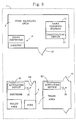
- Figure 1 is a schematic view of a system/method for enhancing hand cleanliness within food handling environment 1 according to a first embodiment of this invention.
- Environment 1 includes food handling area 3, restroom 5, trash area 7, indicator activating device 9 located outside of food handling area 3, hand cleaning station 11 located within food handling area 3, indicator deactivating device 13 operatively associated with hand cleaning station 11, and drink dispenser and cooktop devices 15 disposed within area 3.
- station 11 and deactivating device 13 may be located outside of area 3, but still proximate the food handling area (e.g. near doorway 19).
- Activating device 9 and deactivating device 13 are remotely located relative to one another.
- the system enhances hand cleanliness in food handling area 3 in that activating device 9 continuously outputs activating signal 16 for the purpose of activating passive indicator 17 (see Figure 6) worn by the user.
- indicator 17 is activated in the first embodiment as the user leaves food handling area 3 by way of doorway 19.
- an alarm signal e.g. audio, optical, or vibration type signal
- the user is free to use restroom/bathroom 5 and trash area 7 after leaving area 3 while the indicator is in an activated state.
- Indicator 17 can only be deactivated upon the user reentering food handling area 3 and using hand cleaning station 11.
- deactivating device 13 After the user cleans his/her hands at station 11, deactivating device 13 is triggered to emit signal 42 which "deactivates" indicator 17 such that the alarm signal is no longer emitted or scheduled to be emitted. Any user wearing an "activated” indicator 17 who reenters food handling area 3 and goes about his/her duties without cleaning their hands at station 11 will be targeted as potentially contaminated because their indicator 17 will remain activated and be emitting an alarm signal.
- the system/method according to this invention overcomes the problems discussed above relative to the prior art in that potential contamination of a user between restroom 5 and food handling area 3 is substantially eliminated by deactivating the indicator only upon the user utilizing station 11 which is located proximate or within food handling area 3. This takes care of the situation where the user leaves restroom 5, is contaminated in trash area 7, and thereafter enters food handling area 3.
- FIG. 2 illustrates a second embodiment of this invention similar to that shown in Figure 1, except that activating device 9 is replaced by a pair of activating devices 21 and 23 located in restroom 5 and trash area 7 respectively.
- Activators 21 and 23 each continuously emit activating signals 16.
- the indicator is activated by way of device 21 when the user enters or leaves restroom/bathroom 5 and/or by device 23 as the user enters or leaves trash area 7.
- the user Upon reentering food handling area 3 with passive indicator 17 in the activated state, the user must clean his/her hands at station 11 before device 13 deactivates the indicator via signal 42 thereby extinguishing its alarm signal.
- FIG. 3 is a schematic view of a third embodiment of this invention which differs from the first two embodiments in that indicator activation device 25 is provided in a common area of environment 1 outside of food handling area 3, whereby device 25 continuously emits activating signal(s) 16 which reach restroom 5, trash area 7, and doorway area 19.
- the activating signal(s) 16 output by device 25 are confined within substantially circular signal area 27.
- indicator 17 worn by any user who (i) leaves food handling area 3 by way of door 19; (ii) enters or leaves restroom 5 by way of door 29; or (iii) enters or leaves trash area 7 by way of door 31, is activated by signal 16.
- indicator 17 Upon reentering food handling area 3, indicator 17 remains in the activated and alarm signal emitting state unless deactivated by device 13 following use of station 11.
- Activating signal(s) 16 may be low power RF or alternatively infrared (IR) signals limited to a predetermined emittance area.
- IR infrared
- an RF or IR shielding device may be disposed in and about door area 19 (in a wall or door) so as to prevent signals 16 from entering area 3, and for preventing deactivating signals from station 11 reaching a tag 17 worn outside of area 3.
- FIG 4 is a flowchart illustrating the system of Figures 1-3 in operation.
- the process begins with the user or worker wearing indicator 17 in food handling area 3 while performing his/her duties at 33.
- the indicator 17 being worn by the user is activated by signal 16 in step 35.
- activating step 35 may take place either proximate the exterior of food handling area 3 (Figure 1), in restroom 5, in trash area 7 ( Figure 2), or in a common area 27 outside of food handling area 3 ( Figure 3).
- indicator 17 By receiving signal 16, indicator 17 is placed in an "activated" state which translates into the indicator either immediately or after a predetermined delay period emitting an alarm signal at 37.
- alarm signals include audio beeps, optical blinks, and vibration type signals.
- the predetermined delay period may be, for example, from about 3-15 minutes depending upon the particular application of the invention, although other time periods may also be used.
- indicator 17 When indicator 17 is in an activated state, the user is free to do just about anything except work in food handling area 3 without cleaning his/her hands. There is no cause for concern if indicator 17 is emitting an alarm signal, for example, when a user is taking out the trash (this is expected).
- indicator 17 Upon reentering food handling area 3, indicator 17 will continue to emit an alarm signal putting surrounding personnel on notice of the user's potential contamination until station 11 is utilized by the user for the purpose of cleaning his/her hands at 39.
- step 41 it is determined or detected when the user has completed cleaning his/her hands at station 11.
- deactivating device 13 is triggered to emit deactivating signal 42 in step 43 for the purpose of placing indicator 17 in a deactivated state. Thereafter, the user is free to resume his/her duties in food handling area 3 without having indicator 17 emit an alarm signal.
- Figure 5 is a perspective view of hand cleaning station 11 operatively coupled to deactivating device 13.
- hand cleaning station 11 includes cabinet 45, vertical support 47, sink 49, faucet 51, doors 53, sink top 55, infrared sensor 57 for determining when faucet 51 should output water, dispenser 59 for dispensing toweling 60, and infrared sensor 61 for determining when dispenser 59 should output toweling 60.
- Hand cleaning station 11 is described in further detail in U.S. Patent No. 5,031,258.
- deactivating device 13 is operatively associated with hand cleaning station 11 so that deactivating signal 42 is only emitted upon determination that the user has completed cleaning his/her hands at station 11.
- deactivating device 13 may be coupled to station 11 so that signal 42 is only emitted after infrared sensor 61 causes dispenser 59 to dispense toweling which is utilized by the user. Following the dispensing of toweling 60, deactivating device 13 may be triggered to output signal 42 thereby ensuring that the user's hands are clean before signal 42 is emitted.
- deactivating device 13 may be caused to output signal 42 only after sensor 57 has caused water to be output from faucet 51 and sensor 61 has caused toweling 60 to be output from dispenser 59. According to still further embodiments of this invention, deactivating device 13 may be activated upon the stoppage of water being output from faucet 51.
- the purpose of operatively associating deactivating device 13 with hand cleaning station 11 is to ensure that deactivating signal 42 is only emitted after the user has fully cleaned his/her hands.
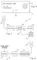
- FIG. 6 is an illustration of indicator 17 to be worn by a user or worker in environment 1.
- indicator 17 may have listed thereon the user's name, identification number, photograph, etc.
- each indicator 17 includes alarm signal output device 61.
- device 61 may be a speaker allowing indicator 17 to emit an audio alarm signal, or alternatively may be a light emitting diode (LED) permitting indicator 17 to emit an optical continuous or blinking alarm signal.
- Indicator 17 further includes receiver 63 for the purpose of receiving both activating signals 16 and deactivating signals 42.
- FIG. 7 is a block diagram of indicator 17, which includes receiver 63, switch/controller 65, timer 67, and alarm signal output device 61. Activating signals 16 are received by receiver 63, and forwarded to switch/controller 65. Depending upon the type of indicator 17, the indicator either immediately outputs an alarm signal via communication 69 to output device 61, or timer 67 is actuated so that the indicator will only begin to emit an alarm signal after a predetermined delay period of time. In both cases, the alarm signal is output via device 61.
- FIG. 8 is block diagram of deactivating device 13 according to certain embodiments of this invention.
- Detector 71 of deactivating device 13 first receives a signal from station 11 indicative of the user having completed cleaning his/her hands (e.g. the received signal having been triggered by the water being shut off or by the towel dispensing being completed).
- Detector 71 causes switch 73 to activate transmitter 75 which emits deactivating signal 42 for a predetermined period of time (e.g. five seconds).
- deactivating device 13 is operatively associated with station 11 so that signal 42 is only emitted after it has been determined that the user has utilized station 11.
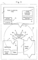
- Figure 9 is a schematic of a system/method for improving hand cleanliness in hospital environment (or doctor office environment) 84 according to another embodiment of this invention.
- the system according to this embodiment functions to help ensure that doctors/nurses wash their hands before handling each patient, so that germs are not conducted from one patient to another by way of medical personnel.
- hand cleaning station 11 with deactivating device 13 are located within (or proximate) patient area 85, while activating devices 9 and 89 are located outside of patient area 85.
- a plurality of additional patient areas 88 are provided in environment 84.
- each such area(s) 88 may have an activating device 89 disposed exterior thereof so that doctors and nurses always enter patient areas 88 and 85 with an activated indicator 17 thereby forcing them to wash their hands before handling the patient in order to deactivate their indicator 17.
- the indicator when a doctor (or nurse) wearing indicator 17 exits patient area 85, the indicator is activated by signal 16 emitted from device 9. Thereafter, the doctor is free to use restroom 5, go to lunch, take care of paper work, etc., with indicator 17 in the activated state.
- the indicator When the doctor reenters area 85, the indicator is activated by signal 16 (if it is not still activated) so that the doctor must use hand cleaning station 11 before device 13 deactivates the indicator. Accordingly, patients and hospital personnel are on notice that a doctor may be contaminated when his/her indicator 17 is emitting an alarm signal.
- all other patient areas 88 in environment 84 are equipped with hand cleaning stations 11 operatively associated with deactivating devices 13 so that medical personnel are forced to wash their hands before seeing each patient, in order to deactivate their indicator 17.
- Figure 10 is a flowchart illustrating another embodiment of this invention wherein indicator 17 is programmed to emit an alarm signal after a predetermined time period if not deactivated by signal 42.
- a predetermined time period may be set so that, for example, indicator 17 worn by a worker handling raw chicken will begin to emit an alarm signal if not deactivated by signal 42 after twenty minutes. This ensures that all chicken handling workers wash their hands at station 11 every twenty minutes thereby reducing the risk of germs, bacteria, etc. from spreading.
- a similar or different time period may be set for beef handling workers.
- the indicator 17 of a beef handling worker may begin to emit an alarm signal if not deactivated by signal 42 following expiration of a thirty minute time period.
- the time period chosen is a matter of design choice and a function of the food being handled. In this manner, the likelihood of germs or bacteria residing in raw chicken being passed on to other food via worker's hands is substantially reduced, thereby resulting in a safer environment 1.
- the process begins at 91 with indicator 17 being turned on or deactivated by signal 42 in area 3 (or 85).
- step 95 it is determined whether or not the indicator 17 is receiving or has just received a deactivation signal 42. If so, step 93 is revisited (i.e. timer 94 is reset). If no deactivation signal 42 has been received, then a determination is made at 97 whether or not T is greater than 0 (i.e. whether the time period has expired). If T is found to be greater than 0, then the countdown continues at step 99.
- step 97 T If, however, in step 97 T is found to be equal to 0 (the time period is expired), then the alarm signal is emitted at 101. The alarm signal will continue to be emitted at 101 until the wearer of the indicator 17 washes his/her hands at station 11 so that the indicator is deactivated by signal 42.
- step 95 is again performed for the purpose of determining whether or not the indicator is or has recently received a deactivation signal 42.
- users in area 3 are required to wash their hands every so often (as dictated by the predetermined time period) in order to keep the alarm signal from being emitted at 101.
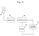
- FIG 11 is a block diagram of indicator 17 in accordance with the Figure 10 embodiment.
- receiver 63 and alarm output 61 are as in Figure 7.
- controller 92 and timer 94 are provided in the indicator.
- the predetermined time period is set by way of timer 94.
- timer 94 is programmed to begin its countdown at the predetermined time period (e.g. twenty minutes for raw chicken handling workers).
- Controller 92 functions to control the operation of timer 94 and alarm output 61.
- controller 92 functions to reset timer 94 when necessary and begins/end alarm output signals.
Abstract
Description
Claims (10)
- A method for enhancing hand cleanliness in an environment requiring clean hands such as a restaurant or a hospital, the method comprising the steps of:characterized by the steps ofproviding a clean area (3) where clean hands are required;providing an indicator (17) to be worn by a user in the clean area (3), the indicator being adapted for generating an alarm signal indicating that the user is potentially contaminated;providing a hand cleaning station (11) proximate or within the clean area (3); andemitting an alarm signal by way of the indicator (17) when it is determined that the user has not used the hand cleaning station (11);activating the indicator (17) worn by the user at a location outside of the clean area (3);deactivating the indicator (17) when it is determined that the user has utilized the hand cleaning station (11) so that the indicator (17) is switched to a deactivated state and the user has clean hands in the clean area; andemitting an alarm signal from the indicator (17) when the indicator (17) does not receive the deactivating signal during a predetermined time period.
- The method according to claim 1, characterized in that the deactivating step takes place inside the clean area (3).
- The method of claim 1 or 2, characterized in that the predetermined time period is counted down after activation of the indicator (17) and the predetermined time period is reset upon the indicator (17) receiving the deactivating signal in said deactivating step.
- The method according to any preceding claim, characterized in that the predetermined time period is less than about one hour.
- Method according to any preceding claim, characterized in that a first radio frequency or infrared signal is emitted in said activating step to activate the indicator (17) and that a second radio frequency or infrared signal different than the first activating signal is emitted in said deactivating step in order to deactivate the indicator (17).
- A system for enhancing hand cleanliness in an environment requiring clean hands such as a restaurant or a hospital, the system comprising:characterized in thata clean area (3) where clean hands are required;a hand cleaning station (11) located proximate or in the clean area (3); andan indicator (17) to be worn by a user in the clean area (3), said indicator (17) being adapted for generating an alarm signal if it does not receive a signal indicating that the hand cleaning station (11) has been used by the user;an activating device (9) is located outside the clean area emitting signals to activate the indicator (17);a deactivating device (13) is operatively associated with said hand cleaning station (11), said deactivating device (13) emitting a deactivating signal which deactivates said indicator (17) when the user has used said hand cleaning station (11), andthe indicator (17) emits the alarm signal when it does not receive a deactivating signal from the deactivating device (13) within a predetermined time period after an activation.
- The system according to claim 6, further comprising means for causing said indicator (17) to generate the alarm signal when the indicator (17) has not been activated for a predetermined period of time.
- The system of claim 6 or 7, further comprising means for causing said deactivating device (13) to emit said deactivating signal after it has been determined that the worker has dried his/her hands by way of a towel dispenser (59) or blower at said hand cleaning station (11).
- The system according to any of claims 6 to 8, further comprising an optical light emitting device, a vibrating device or a buzzer to generate the alarm signal.
- The system according to claim 7 characterized in that the means for causing said indicator (17) to generate the alarm signal includes a timer for counting down said predetermined time period and resetting means for resetting said timer each time the indicator (17) receives the deactivating signal.
Applications Claiming Priority (3)
| Application Number | Priority Date | Filing Date | Title |
|---|---|---|---|
| US08/605,991 US5812059A (en) | 1996-02-23 | 1996-02-23 | Method and system for improving hand cleanliness |
| US605991 | 1996-02-23 | ||
| PCT/US1997/002657 WO1997031350A1 (en) | 1996-02-23 | 1997-02-21 | Method and system for improving hand cleanliness |
Publications (2)
| Publication Number | Publication Date |
|---|---|
| EP0882280A1 EP0882280A1 (en) | 1998-12-09 |
| EP0882280B1 true EP0882280B1 (en) | 2001-11-28 |
Family
ID=24426055
Family Applications (1)
| Application Number | Title | Priority Date | Filing Date |
|---|---|---|---|
| EP97907720A Expired - Lifetime EP0882280B1 (en) | 1996-02-23 | 1997-02-21 | Method and system for improving hand cleanliness |
Country Status (10)
| Country | Link |
|---|---|
| US (1) | US5812059A (en) |
| EP (1) | EP0882280B1 (en) |
| JP (1) | JP3976787B2 (en) |
| AT (1) | ATE209806T1 (en) |
| CA (1) | CA2246338C (en) |
| DE (1) | DE69708606T2 (en) |
| DK (1) | DK0882280T3 (en) |
| ES (1) | ES2166978T3 (en) |
| PT (1) | PT882280E (en) |
| WO (1) | WO1997031350A1 (en) |
Families Citing this family (111)
| Publication number | Priority date | Publication date | Assignee | Title |
|---|---|---|---|---|
| US6236953B1 (en) | 1994-07-12 | 2001-05-22 | Compliance Control, Inc. | System for monitoring compliance with apparatuses having predetermined operating parameters |
| GB2324397A (en) * | 1997-04-16 | 1998-10-21 | Michael Richard Goodier | Hand washing reminder alarm |
| US7010369B2 (en) | 1997-11-07 | 2006-03-07 | Hill-Rom Services, Inc. | Medical equipment controller |
| US5952924A (en) * | 1997-12-04 | 1999-09-14 | Bennie R. Evans | Method and apparatus for enforcing hygiene |
| FR2772059B1 (en) * | 1997-12-08 | 2000-01-14 | Jacques Robaey | DEVICE FOR CONTROLLING ACCESS TO A TOILET CABINET |
| US6236317B1 (en) * | 1998-04-29 | 2001-05-22 | Food Safety Solution Corp. | Method and apparatus for monitoring actions taken by a user for enhancing hygiene |
| US6147607A (en) * | 1998-10-13 | 2000-11-14 | Lynn; John M. | Method and apparatus for helping to assure the washing of hands |
| US6031461A (en) * | 1998-10-13 | 2000-02-29 | Lynn; John M. | Method and apparatus for helping to assure the washing of hands |
| EP1245016A1 (en) * | 1999-10-29 | 2002-10-02 | Hill-Rom Services, Inc. | Hygiene monitoring system |
| US6727818B1 (en) | 1999-10-29 | 2004-04-27 | Hill-Rom Services, Inc. | Hygiene monitoring system |
| US6278372B1 (en) * | 2000-06-01 | 2001-08-21 | Ecolab Inc. | Methods and apparatus for promoting hygiene |
| US6577240B2 (en) * | 2000-06-30 | 2003-06-10 | David N. Armstrong | Hand antiseptic system and method |
| US6392546B1 (en) | 2000-09-07 | 2002-05-21 | Judson L. Smith | Hand washing compliance measurement and recording system |
| US6426701B1 (en) * | 2000-09-20 | 2002-07-30 | Ultraclenz Engineering Group | Handwash monitoring system |
| JP4564179B2 (en) * | 2000-10-17 | 2010-10-20 | サラヤ株式会社 | Fluid supply device |
| US6956498B1 (en) * | 2000-11-02 | 2005-10-18 | Sloan Valve Company | System for remote operation of a personal hygiene or sanitary appliance |
| WO2002059701A1 (en) * | 2001-01-23 | 2002-08-01 | Amron Corporation | Prompts for handwashing |
| EP1390277A1 (en) * | 2001-05-25 | 2004-02-25 | Hill-Rom Services, Inc. | A waste segregation compliance system |
| US20040150526A1 (en) * | 2003-01-17 | 2004-08-05 | De La Garza Javier Roberto | Method of informational advertising in restrooms |
| US7293645B2 (en) * | 2003-01-30 | 2007-11-13 | Judith Lee Harper | Method for monitoring hand hygiene compliance |
| US7774096B2 (en) | 2003-12-31 | 2010-08-10 | Kimberly-Clark Worldwide, Inc. | Apparatus for dispensing and identifying product in washrooms |
| US7783380B2 (en) * | 2003-12-31 | 2010-08-24 | Kimberly-Clark Worldwide, Inc. | System and method for measuring, monitoring and controlling washroom dispensers and products |
| US7690395B2 (en) | 2004-01-12 | 2010-04-06 | Masco Corporation Of Indiana | Multi-mode hands free automatic faucet |
| FR2872315B1 (en) * | 2004-06-24 | 2006-09-01 | Nicolas Bara | SYSTEM FOR VERIFYING COMPLIANCE WITH A PREDEFINED ACTION SEQUENCE |
| US20060067546A1 (en) * | 2004-09-27 | 2006-03-30 | Kimberly-Clark Worldwide, Inc. | Device for encouraging hand wash compliance |
| US20060067545A1 (en) * | 2004-09-27 | 2006-03-30 | Kimberly-Clark Worldwide, Inc. | Device for encouraging hand wash compliance |
| US7443305B2 (en) * | 2004-10-06 | 2008-10-28 | Verdiramo Vincent L | Hand wash monitoring system and method |
| US8294584B2 (en) * | 2004-10-12 | 2012-10-23 | Plost Gerald N | System, method and implementation for increasing a likelihood of improved hand hygiene in a desirably sanitary environment |
| US7423533B1 (en) | 2004-10-19 | 2008-09-09 | Cognetive Systems, Incorporated | System for monitoring and recording cross-contamination events |
| US7782214B1 (en) | 2004-12-31 | 2010-08-24 | Healthmark, Llc | Entertaining or advertising hygiene apparatus |
| GB2425388A (en) * | 2005-04-22 | 2006-10-25 | Rentokil Initial Uk Ltd | Monitoring of hand washing |
| US8502681B2 (en) | 2005-06-20 | 2013-08-06 | Biovigil, Llc | Hand cleanliness |
| US7286057B2 (en) * | 2005-06-20 | 2007-10-23 | Biovigil Llc | Hand cleanliness |
| US7616122B2 (en) | 2005-06-20 | 2009-11-10 | Biovigil, Llc | Hand cleanliness |
| US7936275B2 (en) * | 2005-06-20 | 2011-05-03 | Biovigil, Llc | Hand cleanliness |
| GB2432353B (en) * | 2005-11-22 | 2009-07-15 | James Howard Burton | Intelligent dispensing unit (I.D.U.) |
| US7825812B2 (en) * | 2006-03-16 | 2010-11-02 | Kirk Ogrin | System and method for hand hygiene compliance management and horizontal pump dispenser therefor |
| US7855651B2 (en) * | 2006-04-07 | 2010-12-21 | Cognetive Systems Incorporated | System for monitoring and recording hand hygiene performance |
| US8089473B2 (en) | 2006-04-20 | 2012-01-03 | Masco Corporation Of Indiana | Touch sensor |
| US8118240B2 (en) | 2006-04-20 | 2012-02-21 | Masco Corporation Of Indiana | Pull-out wand |
| US8162236B2 (en) | 2006-04-20 | 2012-04-24 | Masco Corporation Of Indiana | Electronic user interface for electronic mixing of water for residential faucets |
| US8365767B2 (en) | 2006-04-20 | 2013-02-05 | Masco Corporation Of Indiana | User interface for a faucet |
| US9243756B2 (en) | 2006-04-20 | 2016-01-26 | Delta Faucet Company | Capacitive user interface for a faucet and method of forming |
| WO2007127495A2 (en) * | 2006-05-03 | 2007-11-08 | Duke University & Duke University Health Systems | Rf controlled devices to increase compliance with handwashing protocols |
| US7818083B2 (en) | 2006-10-31 | 2010-10-19 | Resurgent Health & Medical, Llc | Automated washing system with compliance verification and automated compliance monitoring reporting |
| US7682464B2 (en) | 2006-10-31 | 2010-03-23 | Resurgent Health & Medical, Llc | Automated washing system with compliance verification |
| US7607442B2 (en) | 2006-10-31 | 2009-10-27 | Resurgent Health & Medical, Llc | Wash chamber for automated appendage-washing apparatus |
| US7698770B2 (en) | 2006-10-31 | 2010-04-20 | Resurgent Health & Medical, Llc | Automated appendage cleaning apparatus with brush |
| US7551092B1 (en) * | 2006-11-15 | 2009-06-23 | Henry Kevin M | Sanitary monitoring system to monitor the hand sanitation of health care workers or other required sanitary activities |
| US20080290112A1 (en) * | 2006-12-11 | 2008-11-27 | John Morris Lynn | Soap dispenser and method for helping assure clean hands |
| US9243392B2 (en) | 2006-12-19 | 2016-01-26 | Delta Faucet Company | Resistive coupling for an automatic faucet |
| WO2008094651A1 (en) | 2007-01-31 | 2008-08-07 | Masco Corporation Of Indiana | Capacitive sensing apparatus and method for faucets |
| US7806141B2 (en) | 2007-01-31 | 2010-10-05 | Masco Corporation Of Indiana | Mixing valve including a molded waterway assembly |
| CA2675417C (en) | 2007-03-28 | 2015-10-13 | Masco Corporation Of Indiana | Improved capacitive touch sensor |
| US8237558B2 (en) | 2007-03-30 | 2012-08-07 | University Health Network | Hand hygiene compliance system |
| WO2008119158A1 (en) | 2007-03-30 | 2008-10-09 | Toronto Rehabilitation Institute | Hand hygiene compliance system |
| US20090031020A1 (en) * | 2007-07-27 | 2009-01-29 | Luis Garcia | Apparatus and method for monitoring use of resources by healthcare employees |
| US7893842B2 (en) | 2007-10-05 | 2011-02-22 | Richard Deutsch | Systems and methods for monitoring health care workers and patients |
| CA2704577C (en) | 2007-11-05 | 2015-10-27 | Sloan Valve Company | Restroom convenience center |
| EP2235272A1 (en) | 2007-12-11 | 2010-10-06 | Masco Corporation Of Indiana | Capacitive coupling arrangement for a faucet |
| GB2457930A (en) * | 2008-02-29 | 2009-09-02 | Peter Sage-Passant | Handwash monitoring system |
| US20090224924A1 (en) * | 2008-03-10 | 2009-09-10 | Thorp Robert B | System and method for positively reinforcing hand-hygeine compliance |
| US8212653B1 (en) | 2008-03-20 | 2012-07-03 | The General Hospital Corp. | Protected zone system |
| US8377229B2 (en) | 2008-04-29 | 2013-02-19 | Resurgent Health & Medical, Llc | Ingress/egress system for hygiene compliance |
| US8639527B2 (en) | 2008-04-30 | 2014-01-28 | Ecolab Usa Inc. | Validated healthcare cleaning and sanitizing practices |
| CA2722489C (en) | 2008-04-30 | 2018-05-22 | Ecolab Inc. | Validated healthcare cleaning and sanitizing practices |
| WO2010015968A1 (en) * | 2008-08-05 | 2010-02-11 | Philips Intellectual Property & Standards Gmbh | Patient monitoring system |
| AU2009288787A1 (en) * | 2008-09-03 | 2010-03-11 | Hyginex Inc. | Methods and systems for monitoring hygiene habits |
| US20100094581A1 (en) * | 2008-10-06 | 2010-04-15 | Ron Cagle | Method for tracking and reporting personal hand hygiene dispenser electronic time-stamp data |
| CA2668078A1 (en) * | 2009-06-05 | 2010-12-05 | Georges Raymond Brow | Automated hand washing reminder system for an entranceway |
| US9873559B2 (en) * | 2009-06-09 | 2018-01-23 | Sca Hygiene Products Ab | Dispensing system and method for dispensing a product |
| EP2441062B1 (en) | 2009-06-12 | 2015-09-23 | Ecolab USA Inc. | Hand hygiene compliance monitoring |
| USRE48951E1 (en) | 2015-08-05 | 2022-03-01 | Ecolab Usa Inc. | Hand hygiene compliance monitoring |
| US8547220B1 (en) | 2009-06-18 | 2013-10-01 | The General Hospital Corporation | Ultrasonic compliance zone system |
| US8164439B2 (en) * | 2009-06-18 | 2012-04-24 | The General Hospital Corp. | Ultrasonic compliance zone system |
| US20100328443A1 (en) * | 2009-06-26 | 2010-12-30 | Lynam Donald S | System for monitoring patient safety suited for determining compliance with hand hygiene guidelines |
| US8350706B2 (en) * | 2009-06-30 | 2013-01-08 | Gojo Industries, Inc. | Hygiene compliance monitoring system |
| GB0913564D0 (en) * | 2009-08-04 | 2009-09-16 | Pulse Medical Technologies Ltd | System, apparatus and method for enabling hand hygiene |
| EP2481033A4 (en) * | 2009-09-25 | 2013-10-30 | 3M Innovative Properties Co | Hygiene monitoring systems and methods |
| JP2013508820A (en) * | 2009-10-15 | 2013-03-07 | スリーエム イノベイティブ プロパティズ カンパニー | Medical delivery monitoring system and method |
| US20110121974A1 (en) * | 2009-11-20 | 2011-05-26 | Versus Technology, Inc. | Real-time method and system for monitoring hygiene compliance within a tracking environment |
| US8140258B1 (en) | 2010-03-02 | 2012-03-20 | The General Hospital Corporation | Wayfinding system |
| US8776817B2 (en) | 2010-04-20 | 2014-07-15 | Masco Corporation Of Indiana | Electronic faucet with a capacitive sensing system and a method therefor |
| US8561626B2 (en) | 2010-04-20 | 2013-10-22 | Masco Corporation Of Indiana | Capacitive sensing system and method for operating a faucet |
| WO2011149884A2 (en) | 2010-05-24 | 2011-12-01 | Georgia-Pacific Consumer Products Lp | Hand hygiene compliance system |
| US9672726B2 (en) | 2010-11-08 | 2017-06-06 | Georgia-Pacific Consumer Products Lp | Hand hygiene compliance monitoring system |
| US20140210620A1 (en) | 2013-01-25 | 2014-07-31 | Ultraclenz Llc | Wireless communication for dispenser beacons |
| HK1150410A2 (en) * | 2011-05-04 | 2011-12-23 | Gen Sensing Ltd | System and method for reducing medical error |
| GB2510515B (en) | 2011-10-14 | 2017-07-26 | Caiwd Llc | Sanitization protocol monitoring/compliance systems, apparatuses, methods, and software |
| US20130229276A1 (en) * | 2012-03-02 | 2013-09-05 | Desiree Hunter | Systems and Methods for Providing Hand Washing and Sanitizing Alerts |
| US9135805B2 (en) | 2012-03-27 | 2015-09-15 | IntelligentM | Methods and systems for encouraging and enforcing hand hygiene |
| EP2859153A4 (en) | 2012-04-20 | 2016-06-22 | Masco Corp | Faucet including a pullout wand with capacitive sensing |
| WO2014037938A2 (en) | 2012-09-04 | 2014-03-13 | Hyginex Israel Ltd. | Infectious disease spread prevention |
| WO2015021528A1 (en) | 2013-08-12 | 2015-02-19 | University Health Network | Hand hygiene compliance |
| EP3117415B1 (en) | 2014-03-10 | 2023-10-18 | Gojo Industries, Inc. | Hygiene tracking compliance |
| US9830764B1 (en) | 2014-04-09 | 2017-11-28 | Gpcp Ip Holdings Llc | Universal dispenser interface |
| US9472089B2 (en) * | 2014-08-05 | 2016-10-18 | Raed H. AlHazme | Method and system for monitoring and enforcing hand hygiene and sanitization |
| CA2976186C (en) * | 2015-02-25 | 2024-02-20 | Kimberly-Clark Worldwide, Inc. | Method and system for consumer award program for washroom usage |
| KR101817577B1 (en) | 2015-03-30 | 2018-02-21 | 킴벌리-클라크 월드와이드, 인크. | Systems and methods for directing personnel to maintain washroom requirements |
| US9542828B1 (en) | 2015-06-22 | 2017-01-10 | Peter D. Haaland | System, device, and method for measurement of hand hygiene technique |
| US9773403B2 (en) | 2015-07-28 | 2017-09-26 | Hill-Rom Services, Inc. | Hygiene compliance system |
| US10607471B2 (en) | 2015-10-06 | 2020-03-31 | Hill-Rom Services, Inc. | Hand hygiene monitoring system with customizable thresholds |
| US10002518B1 (en) | 2016-02-18 | 2018-06-19 | OND Creative Solutions, LLC | System and method of biological and germ cross contamination control |
| US10332382B2 (en) | 2016-04-08 | 2019-06-25 | Hand-Scan, LLC | System and method for monitoring handwashing compliance including soap dispenser with integral hand-washing monitor and smart button system |
| US10235865B2 (en) | 2016-04-08 | 2019-03-19 | Hand Scan Llc | System and method for monitoring handwashing compliance |
| US11272815B2 (en) | 2017-03-07 | 2022-03-15 | Ecolab Usa Inc. | Monitoring modules for hand hygiene dispensers |
| US11069220B2 (en) | 2017-07-10 | 2021-07-20 | Biovigil Hygiene Technologies, Llc | Hand cleanliness monitoring |
| US10529219B2 (en) | 2017-11-10 | 2020-01-07 | Ecolab Usa Inc. | Hand hygiene compliance monitoring |
| US11284333B2 (en) | 2018-12-20 | 2022-03-22 | Ecolab Usa Inc. | Adaptive route, bi-directional network communication |
| CN112274079B (en) * | 2020-09-25 | 2022-04-05 | 华帝股份有限公司 | Cleaning control method for cooking equipment and cooking equipment applying same |
| US20220122447A1 (en) * | 2020-10-19 | 2022-04-21 | Gojo Industries, Inc. | Smart tags for covertly promoting hand hygiene compliance in food service industries |
Family Cites Families (14)
| Publication number | Priority date | Publication date | Assignee | Title |
|---|---|---|---|---|
| US3967478A (en) * | 1975-06-09 | 1976-07-06 | Guinn Stanley G | Door latching apparatus actuated by cleansing agent sensor |
| US4158197A (en) * | 1977-10-21 | 1979-06-12 | Mitsuhiro Takagaki | Pendant with an alarm built in |
| US4598275A (en) * | 1983-05-09 | 1986-07-01 | Marc Industries Incorporated | Movement monitor |
| US4654793A (en) * | 1984-10-15 | 1987-03-31 | Showdata, Inc. | System and method for registering and keeping track of the activities of attendees at a trade show, convention or the like |
| US4837559A (en) * | 1987-12-10 | 1989-06-06 | Green Sr James G | Personal security device |
| US4896144A (en) * | 1988-09-29 | 1990-01-23 | Bogstad Naomi C | Hand washing alert |
| US5031258A (en) * | 1989-07-12 | 1991-07-16 | Bauer Industries Inc. | Wash station and method of operation |
| US5135721A (en) * | 1990-01-18 | 1992-08-04 | Net/Tech International, Inc. | Sterilization and coating apparatus |
| US5103474A (en) * | 1990-05-08 | 1992-04-07 | Digital Products Corporation | Drive-by personnel monitoring system with radio link |
| US5202666A (en) * | 1991-01-18 | 1993-04-13 | Net/Tech International Inc. | Method and apparatus for enhancing hygiene |
| US5341126A (en) * | 1991-12-26 | 1994-08-23 | Boykin Roger O | Selective exit control system |
| US5307763A (en) * | 1992-05-13 | 1994-05-03 | Arthur David L | Restricted area alarm system |
| JP2723452B2 (en) * | 1993-08-23 | 1998-03-09 | 株式会社多川商事 | Self-sounding tag alarm device |
| US5610589A (en) * | 1995-02-09 | 1997-03-11 | Bennie R. Evans | Method and apparatus for enforcing hygiene |
-
1996
- 1996-02-23 US US08/605,991 patent/US5812059A/en not_active Expired - Lifetime
-
1997
- 1997-02-21 WO PCT/US1997/002657 patent/WO1997031350A1/en active IP Right Grant
- 1997-02-21 ES ES97907720T patent/ES2166978T3/en not_active Expired - Lifetime
- 1997-02-21 CA CA002246338A patent/CA2246338C/en not_active Expired - Lifetime
- 1997-02-21 EP EP97907720A patent/EP0882280B1/en not_active Expired - Lifetime
- 1997-02-21 DK DK97907720T patent/DK0882280T3/en active
- 1997-02-21 JP JP53031597A patent/JP3976787B2/en not_active Expired - Fee Related
- 1997-02-21 PT PT97907720T patent/PT882280E/en unknown
- 1997-02-21 AT AT97907720T patent/ATE209806T1/en not_active IP Right Cessation
- 1997-02-21 DE DE69708606T patent/DE69708606T2/en not_active Expired - Lifetime
Also Published As
| Publication number | Publication date |
|---|---|
| DE69708606D1 (en) | 2002-01-10 |
| DK0882280T3 (en) | 2002-03-25 |
| JP3976787B2 (en) | 2007-09-19 |
| WO1997031350A1 (en) | 1997-08-28 |
| PT882280E (en) | 2002-05-31 |
| CA2246338C (en) | 2005-05-31 |
| DE69708606T2 (en) | 2002-08-01 |
| JP2000505576A (en) | 2000-05-09 |
| EP0882280A1 (en) | 1998-12-09 |
| ATE209806T1 (en) | 2001-12-15 |
| ES2166978T3 (en) | 2002-05-01 |
| US5812059A (en) | 1998-09-22 |
| CA2246338A1 (en) | 1997-08-28 |
Similar Documents
| Publication | Publication Date | Title |
|---|---|---|
| EP0882280B1 (en) | Method and system for improving hand cleanliness | |
| US5670945A (en) | Self-monitoring hand-sanitizing station | |
| JP3281375B2 (en) | Method and apparatus for enhancing hygiene | |
| US9922534B2 (en) | Automatic hygiene compliance assistance | |
| US9715817B2 (en) | Hygiene monitoring system | |
| US7551092B1 (en) | Sanitary monitoring system to monitor the hand sanitation of health care workers or other required sanitary activities | |
| AU2010322439B2 (en) | Real-time method and system for monitoring hygiene compliance within a tracking environment | |
| US9940819B2 (en) | Systems and methods for encouraging hand washing compliance | |
| US6577240B2 (en) | Hand antiseptic system and method | |
| US6426701B1 (en) | Handwash monitoring system | |
| US11779167B2 (en) | Dispensing and monitoring systems and methods | |
| US20060272361A1 (en) | Handwash monitoring system | |
| CA2388763A1 (en) | Hygiene monitoring system | |
| JP2013506200A (en) | Hygiene monitoring system and method | |
| US20120002510A1 (en) | System and apparatus for automatically ensuring the appropriate duration for handwashing | |
| WO2015117112A1 (en) | Real-time method and system for monitoring hygiene compliance within a tracking environment utilizing various timers | |
| EP3531885B1 (en) | A system for enhancing hand hygiene |
Legal Events
| Date | Code | Title | Description |
|---|---|---|---|
| PUAI | Public reference made under article 153(3) epc to a published international application that has entered the european phase |
Free format text: ORIGINAL CODE: 0009012 |
|
| 17P | Request for examination filed |
Effective date: 19980904 |
|
| AK | Designated contracting states |
Kind code of ref document: A1 Designated state(s): AT BE CH DE DK ES FR GB IT LI PT SE |
|
| 17Q | First examination report despatched |
Effective date: 20001018 |
|
| GRAG | Despatch of communication of intention to grant |
Free format text: ORIGINAL CODE: EPIDOS AGRA |
|
| GRAG | Despatch of communication of intention to grant |
Free format text: ORIGINAL CODE: EPIDOS AGRA |
|
| GRAH | Despatch of communication of intention to grant a patent |
Free format text: ORIGINAL CODE: EPIDOS IGRA |
|
| GRAH | Despatch of communication of intention to grant a patent |
Free format text: ORIGINAL CODE: EPIDOS IGRA |
|
| GRAA | (expected) grant |
Free format text: ORIGINAL CODE: 0009210 |
|
| AK | Designated contracting states |
Kind code of ref document: B1 Designated state(s): AT BE CH DE DK ES FR GB IT LI PT SE |
|
| REF | Corresponds to: |
Ref document number: 209806 Country of ref document: AT Date of ref document: 20011215 Kind code of ref document: T |
|
| REG | Reference to a national code |
Ref country code: CH Ref legal event code: EP |
|
| REG | Reference to a national code |
Ref country code: GB Ref legal event code: IF02 |
|
| REF | Corresponds to: |
Ref document number: 69708606 Country of ref document: DE Date of ref document: 20020110 |
|
| ET | Fr: translation filed | ||
| REG | Reference to a national code |
Ref country code: DK Ref legal event code: T3 |
|
| REG | Reference to a national code |
Ref country code: ES Ref legal event code: FG2A Ref document number: 2166978 Country of ref document: ES Kind code of ref document: T3 |
|
| REG | Reference to a national code |
Ref country code: PT Ref legal event code: SC4A Free format text: AVAILABILITY OF NATIONAL TRANSLATION Effective date: 20020215 |
|
| PLBE | No opposition filed within time limit |
Free format text: ORIGINAL CODE: 0009261 |
|
| STAA | Information on the status of an ep patent application or granted ep patent |
Free format text: STATUS: NO OPPOSITION FILED WITHIN TIME LIMIT |
|
| 26N | No opposition filed | ||
| PGFP | Annual fee paid to national office [announced via postgrant information from national office to epo] |
Ref country code: DK Payment date: 20040123 Year of fee payment: 8 |
|
| PGFP | Annual fee paid to national office [announced via postgrant information from national office to epo] |
Ref country code: PT Payment date: 20040216 Year of fee payment: 8 |
|
| PGFP | Annual fee paid to national office [announced via postgrant information from national office to epo] |
Ref country code: AT Payment date: 20040220 Year of fee payment: 8 |
|
| PGFP | Annual fee paid to national office [announced via postgrant information from national office to epo] |
Ref country code: ES Payment date: 20040223 Year of fee payment: 8 Ref country code: CH Payment date: 20040223 Year of fee payment: 8 |
|
| PGFP | Annual fee paid to national office [announced via postgrant information from national office to epo] |
Ref country code: BE Payment date: 20040308 Year of fee payment: 8 |
|
| PG25 | Lapsed in a contracting state [announced via postgrant information from national office to epo] |
Ref country code: AT Free format text: LAPSE BECAUSE OF NON-PAYMENT OF DUE FEES Effective date: 20050221 |
|
| PG25 | Lapsed in a contracting state [announced via postgrant information from national office to epo] |
Ref country code: ES Free format text: LAPSE BECAUSE OF NON-PAYMENT OF DUE FEES Effective date: 20050222 |
|
| PG25 | Lapsed in a contracting state [announced via postgrant information from national office to epo] |
Ref country code: LI Free format text: LAPSE BECAUSE OF NON-PAYMENT OF DUE FEES Effective date: 20050228 Ref country code: DK Free format text: LAPSE BECAUSE OF NON-PAYMENT OF DUE FEES Effective date: 20050228 Ref country code: CH Free format text: LAPSE BECAUSE OF NON-PAYMENT OF DUE FEES Effective date: 20050228 Ref country code: BE Free format text: LAPSE BECAUSE OF NON-PAYMENT OF DUE FEES Effective date: 20050228 |
|
| PG25 | Lapsed in a contracting state [announced via postgrant information from national office to epo] |
Ref country code: PT Free format text: LAPSE BECAUSE OF NON-PAYMENT OF DUE FEES Effective date: 20050822 |
|
| BERE | Be: lapsed |
Owner name: *SLOAN VALVE CY Effective date: 20050228 |
|
| REG | Reference to a national code |
Ref country code: DK Ref legal event code: EBP |
|
| REG | Reference to a national code |
Ref country code: CH Ref legal event code: PL |
|
| REG | Reference to a national code |
Ref country code: PT Ref legal event code: MM4A Effective date: 20050822 |
|
| REG | Reference to a national code |
Ref country code: ES Ref legal event code: FD2A Effective date: 20050222 |
|
| BERE | Be: lapsed |
Owner name: *SLOAN VALVE CY Effective date: 20050228 |
|
| PGFP | Annual fee paid to national office [announced via postgrant information from national office to epo] |
Ref country code: SE Payment date: 20140227 Year of fee payment: 18 |
|
| REG | Reference to a national code |
Ref country code: FR Ref legal event code: PLFP Year of fee payment: 19 |
|
| PGFP | Annual fee paid to national office [announced via postgrant information from national office to epo] |
Ref country code: IT Payment date: 20150225 Year of fee payment: 19 |
|
| PGFP | Annual fee paid to national office [announced via postgrant information from national office to epo] |
Ref country code: FR Payment date: 20150217 Year of fee payment: 19 Ref country code: GB Payment date: 20150226 Year of fee payment: 19 |
|
| REG | Reference to a national code |
Ref country code: SE Ref legal event code: EUG |
|
| PG25 | Lapsed in a contracting state [announced via postgrant information from national office to epo] |
Ref country code: SE Free format text: LAPSE BECAUSE OF NON-PAYMENT OF DUE FEES Effective date: 20150222 |
|
| PGFP | Annual fee paid to national office [announced via postgrant information from national office to epo] |
Ref country code: DE Payment date: 20160226 Year of fee payment: 20 |
|
| GBPC | Gb: european patent ceased through non-payment of renewal fee |
Effective date: 20160221 |
|
| REG | Reference to a national code |
Ref country code: FR Ref legal event code: ST Effective date: 20161028 |
|
| PG25 | Lapsed in a contracting state [announced via postgrant information from national office to epo] |
Ref country code: IT Free format text: LAPSE BECAUSE OF NON-PAYMENT OF DUE FEES Effective date: 20160221 |
|
| PG25 | Lapsed in a contracting state [announced via postgrant information from national office to epo] |
Ref country code: FR Free format text: LAPSE BECAUSE OF NON-PAYMENT OF DUE FEES Effective date: 20160229 Ref country code: GB Free format text: LAPSE BECAUSE OF NON-PAYMENT OF DUE FEES Effective date: 20160221 |
|
| REG | Reference to a national code |
Ref country code: DE Ref legal event code: R071 Ref document number: 69708606 Country of ref document: DE |