EP0882955A1 - Level measuring apparatus using microwaves - Google Patents
Level measuring apparatus using microwaves Download PDFInfo
- Publication number
- EP0882955A1 EP0882955A1 EP97109195A EP97109195A EP0882955A1 EP 0882955 A1 EP0882955 A1 EP 0882955A1 EP 97109195 A EP97109195 A EP 97109195A EP 97109195 A EP97109195 A EP 97109195A EP 0882955 A1 EP0882955 A1 EP 0882955A1
- Authority
- EP
- European Patent Office
- Prior art keywords
- line
- section
- microwave
- shield
- antenna
- Prior art date
- Legal status (The legal status is an assumption and is not a legal conclusion. Google has not performed a legal analysis and makes no representation as to the accuracy of the status listed.)
- Granted
Links
Images


Classifications
-
- G—PHYSICS
- G01—MEASURING; TESTING
- G01F—MEASURING VOLUME, VOLUME FLOW, MASS FLOW OR LIQUID LEVEL; METERING BY VOLUME
- G01F23/00—Indicating or measuring liquid level or level of fluent solid material, e.g. indicating in terms of volume or indicating by means of an alarm
- G01F23/22—Indicating or measuring liquid level or level of fluent solid material, e.g. indicating in terms of volume or indicating by means of an alarm by measuring physical variables, other than linear dimensions, pressure or weight, dependent on the level to be measured, e.g. by difference of heat transfer of steam or water
- G01F23/28—Indicating or measuring liquid level or level of fluent solid material, e.g. indicating in terms of volume or indicating by means of an alarm by measuring physical variables, other than linear dimensions, pressure or weight, dependent on the level to be measured, e.g. by difference of heat transfer of steam or water by measuring the variations of parameters of electromagnetic or acoustic waves applied directly to the liquid or fluent solid material
- G01F23/284—Electromagnetic waves
Definitions
- the invention relates to a working with microwaves Level measuring device.
- Level measuring instruments working with microwaves are in almost all branches of industry, e.g. in chemistry and the Food industry. They usually serve to monitor fill levels in containers and / or display.
- Microwave levels are measured using a Antenna sent to the surface of a product and on the Echo waves reflected from the surface received. It will be one representing the echo amplitudes as a function of distance Echo function formed from which the likely useful echo and its duration can be determined. The runtime becomes the distance between the product surface and the antenna certainly.
- wave packets With pulse radar, short microwave transmission pulses are periodically hereinafter referred to as wave packets, sent, which is reflected by the product surface and received again after a distance-dependent runtime will.
- the received signal amplitude as a function of Time represents the echo function. Any value of this Echo function corresponds to the amplitude of one in one certain distance from the antenna reflected echoes.
- the FMCW process uses a continuous microwave sent, which is periodically linear frequency modulated, for example after a sawtooth function.
- the frequency of the received echo signal therefore points towards the Instantaneous frequency, which the transmission signal at the time of Has a frequency difference on the reception Duration of the echo signal depends.
- the frequency difference between transmit signal and receive signal by mixing both signals and evaluation of the Fourier spectrum of the Mixed signal can be obtained corresponds to that Distance of the reflecting surface from the antenna. Further correspond to the amplitudes of the spectral lines of the Fourier transform obtained frequency spectrum Echo amplitudes. This Fourier spectrum therefore represents in in this case represents the echo function.
- level gauges For security reasons, it is especially with Use of level gauges in environments in which There is a risk of explosion with a galvanic one Separation between the measuring device and the process, e.g. the Interior of a container whose level is to be measured, to attach. This prevents sparking.
- the requirements for galvanic isolation in Certain applications can be made from country to country Country may be different. They are usually in standards, e.g. the European industrial standard EN 50020.
- the galvanic is carried out Separation in an input module. It will all follow external electrical connections, i.e. usually at least two supply lines, at least one measurement signal line and a line over the Information on times of transmission of microwave pulses at Pulse radar or over a period beginning with the FMCW radar are transmitted, galvanically isolated.
- the microwave line one arranged on a first side of a circuit board
- the coplanar line is the one on each side of the Signal line a shield line is arranged, and the first and second capacitors are on the first Components arranged on the side of the circuit board.
- the Microwave line one arranged on a circuit board Microstrip line, on which on a first side of the Circuit board a signal line and a first capacitor are arranged and in which on a second of the first Side opposite side of the board at least one Shield line and at least one second capacitor is arranged.
- the microwave line a coplanar line arranged on a circuit board, one on each side of the signal line Shield line is arranged, the first with the Generator connected section in which the Signal line and the shield lines on a first Side of the board are arranged, and the second section connected to the antenna, in which the Signal line and the shield lines on a second of the first side opposite side of the board are arranged, the first and the second section overlap the microwave line, the first Capacitor through overlapping areas of the signal lines of the first and second sections and one in between located area of the board is formed and wherein the second capacitors through overlapping areas of the Shield lines of the first and second sections and Intermediate areas of the board are formed.
- the microwave line a first section in which the Microwave line one arranged on a circuit board Coplanar line is, on the first side of the Board a signal line and to each side of the Signal line one shield line is arranged, and they has a second section in which the Microwave line is a microstrip line, the one signal line running on the first side of the board and at least one on a second of the first page opposite side of the board Has shield line, the first and the second Section of the microwave line overlap, the first capacitor on the first side of the board is arranged, the second capacitors through overlapping areas of the shield lines of the first and of the second section and areas in between the board are formed, and being either the first Section with the antenna and the second section with the Generator or vice versa the second section with the Antenna and the first section connected to the generator is.
- the microwave line a coaxial line, one with the generator connected first section and one with the antenna connected second section.
- the first capacitor has two opposite each other in the middle of the plate arranged electrodes, one of which facing the generator Electrode with the signal line of the first Section and an antenna-facing electrode with the Signal line of the second section of the microwave line is connected
- the second capacitor has two each on an outer edge of the plate oppositely arranged ring electrodes, of which a generator-facing ring electrode with the Shield line of the first section and an antenna facing Ring electrode with the shield line of the second Section of the microwave line is connected.
- a between the shield line and the signal line of the second section of the microwave line existing Cavity filled with an insulator, especially with glass.
- An advantage of the invention is that the galvanic isolation on the radio frequency side, i.e. between the Generator and the antenna is done. In this place is only a single line, namely the microwave line, to be galvanically separated. As a result, the use of im Comparison to DC-DC converters or Optocouplers inexpensive capacitors possible.
- Another advantage is that existing ones Level gauges that have not previously been used in potentially explosive atmospheres Areas could be used with a galvanic isolation can be retrofitted.
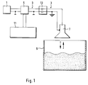
- Fig. 1 is a level measuring device working with microwaves shown schematically.
- the microwaves are generated by a generator 1.
- a generator 1 for example, this is a Pulse radar device, an FMCW device or a continuous vibrating microwave oscillator that sends a signal generated.
- the transmission signal is transmitted via a transceiver 5, e.g. a directional coupler, to one above a container 9 arranged antenna 7 transmitted.
- a transceiver 5 e.g. a directional coupler
- From the send-receive switch 5 leads a microwave line 3 to Antenna 7.
- This is for example one on a board arranged microstrip line, a coplanar line, a combination of microstrip and coplanar lines or a coaxial line.
- a coplanar line has three parallel to each other a planar line structure applied to a circuit board, a middle one is a signal line and two outer shield cables are in each case.
- a microstrip line has one on a first side a planar line structure arranged on a circuit board serves as a signal line. On one of the first pages opposite side of the board is another one planar line structure applied, which is usually is significantly wider than the signal line and as Shield wire is used.
- the container 9 contains a filling material whose level is too determine is. Microwaves emitted by the antenna 7 are reflected on the surface of the product and the Echo waves are picked up by the antenna 7. A The corresponding receive signal is via the send / receive switch 5 a reception and evaluation circuit 11 fed. This is from the same transmit / receive switch 5 Generator 1 generated transmission signal of the receive and Evaluation circuit 11 supplied. From the two signals is the distance between antenna 7 and product surface certainly. Since the distance between the antenna 7 and the Container bottom is known, this results directly from the level to be measured.
- the antenna 7 is e.g. one from an electrically conductive Material, e.g. made of aluminum or a stainless steel, existing horn or a rod-shaped antenna a dielectric, e.g. made of polytetrafluoroethylene (PTFE).
- an electrically conductive Material e.g. made of aluminum or a stainless steel
- existing horn or a rod-shaped antenna a dielectric, e.g. made of polytetrafluoroethylene (PTFE).
- PTFE polytetrafluoroethylene
- the latter antenna form is often also called dielectric stem radiator called.
- the microwave line 3 has a galvanic isolation 13.
- Figures 2 to 7 are five embodiments shown.
- the microwave line 3 has exemplary embodiments one signal line each and at least one Shield line on. There is one in each of the signal lines first capacitor for galvanic isolation of the Signal line inserted and in each shield line a second capacitor for electrical isolation of the respective shield line inserted.
- the capacitors have mechanically strong insulation, in the event of an error, e.g. with high overload, high resistance and have a high dielectric strength, e.g. from 500 V to.
- the Microwave line 3 one on a first side of one Circuit board 15 arranged coplanar line.
- One of the first Side opposite second side of the board 15 either free or with a metallic coating provided and with a reference potential, e.g. Dimensions, connected.
- the coplanar line consists of three in parallel applied to each other on the board 15 planar line structures.
- the middle line serves as Signal line 17a and on both sides of the signal line A shielding line 19a runs in each case 17a.
- the signal line 17a is on the first side of the Board 15 inserted a first capacitor 21a through which the signal line 17a is electrically isolated.
- the shield lines 19a are on the first side Board 15 inserted second capacitors 23a through the shield lines 19a are electrically isolated.
- the capacitors 21a, 23a are e.g. commercially available for Microwaves suitable also mountable on a board components referred to as surface-mounted devices.
- the generator-facing side On the generator-facing side are the Signal line 17a and shield lines 19a floating with the Generator 1 connected. Because of the freedom from earth Equipotential bonding lines, e.g. from a supply to Measuring device, largely unnecessary.
- the antenna facing Side On the antenna facing Side is the signal line 17a with an in the antenna 7 arranged in the figure, not shown Exciter element connected. The excitation element is used for this Microwaves from the microwave line 3 into the antenna 7 to couple and vice versa recorded by the antenna 7 To couple microwaves into the microwave line 3.
- the Shield lines 19a of the section II facing the antenna are connected to earth potential.
- the antenna 7 is on dielectric stem radiator, so is its metallic Attachment connected to the earth potential. Is the antenna 7 a horn, the metallic horn with the Earth potential connected.
- FIG. 3 shows a further exemplary embodiment of that in FIG. 1 shown microwave line 3.
- a microwave line 3 serves here one arranged on the board 15 Microstrip line.
- a signal line 17b is on one first side of the board 15 arranged.
- On the first one Side opposite second side of the board 15 is a shield line 19b is arranged.
- the microwave line 3 is also here by first and second capacitors 21b, 23b divided into two sections I, II, namely a first connected to the generator 1 section I and a second section II connected to the antenna 7.
- the capacitors 21b, 23b attached to the circuit board 15 and cause one galvanic isolation of the signal line 17b and Shield line 19b.
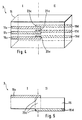
- Fig. 4 shows a further embodiment in which the Microwave line 3 arranged on a circuit board 15 Coplanar line is.
- the microwave line 3 is too here by first and second capacitors 21c, 23c in two Sections I, II divided, namely a first with the Generator 1 connected section I and a second one the antenna 7 connected section II.
- first section I a signal line 17c and two shield lines 19c on the first side of the board 15 arranged.
- second section II are one Signal line 17d and two shield lines 19d on the second side of the page opposite the first Board 15 arranged.
- the two sections I and II overlap.
- the antenna-facing ends of the Signal line 17c and the shield lines 19c of the first Section I are each facing the generator Ends of the corresponding signal line 17d or Shield line 19d of the second section II is arranged.
- the overlapping areas close one in between located area of the board 15.
- FIG. 5 shows a section through the microwave line 3 4, from which the overlap of sections I and II and the capacitors thus formed, using the example of Shield lines 19c, 19d and the second capacitor 23c, are shown.
- broadband transmission characteristics achieve by preferring the ends significantly wider than the actual lines are and have the shape of a quarter circle. Is too through this geometry the impedance jump at the transition less large and therefore less microwave radiation reflected.
- An advantage of the last described microwave line 3 is that no additional capacitors are required are, but instead the already existing board 15 is being used.
- the signal line is on the side facing the generator 17c and shield lines 19c floating with the generator 1 connected.
- On the side facing the antenna is the Signal line 17d with one arranged in the antenna 7 exciter element not shown in the figure.
- the excitation element serves microwaves from the To couple microwave line 3 in the antenna 7 and vice versa microwaves picked up by the antenna 7 in the To couple microwave line 3.
- the shield lines 19d of the antenna-facing section II are with Earth potential connected.
- the antenna 7 is on dielectric stem radiator, so is its metallic Attachment connected to the earth potential. Is the antenna 7 a horn, the metallic horn with the Earth potential connected.
- the microwave line 3 has a first with the generator 1 connected section I on, called the coplanar conduit is trained.
- a second one connected to the antenna 7 Section II of the microwave line 3 is as Microstrip line formed. Both sections I, II are arranged on the same board 15.
- a signal line 17e is both in the first and in the second section I, II on the first side of the board 15 arranged. In the first section I is on each side Signal line 17e each have a shield line 19e arranged.
- a shield line 19f arranged on the second side of the board 15 is in the second Section II .
- This consists of a metallic coated area of the second side of the board 15.
- the first and the second Sections I and II overlap.
- An antenna-facing End of each one on the first side of the board 15 arranged shield lines 19e thus covers the Metallically coated area, the shield line 19f of the second section II.
- shield line 19f can of course also be two or more individual e.g. strip-shaped shield cables on the second side of the Board 15 may be applied. It just has to be guaranteed be that there is sufficient overlap between the Shield lines 19e of the first section I and the or the shield lines of the second section II.
- the first capacitor 21e is on the first side of the Board 15 inserted into the signal line 17e.
- the second Capacitors 23e are through the overlapping areas of the Shield lines 19e of the first and 19f of the second Section II and intermediate areas of the Board 15 formed.
- the ends of the shield lines 19e facing the antenna are widened compared to the actual shield lines 19e and have the shape of a quarter circle.
- the impedance jump for microwave radiation at the transition from the first to the second section is less large and therefore less microwave radiation is reflected.
- the frequency range by this provides favorable transmission properties Geometry broadened.
- Other end geometries, e.g. those designed for a special use Microwave radiation are also adjusted applicable.
- microwave line 3 of Fig. 6 also used in reverse orientation will. This would correspond to that as a coplanar line trained first section I with the antenna 7 and second section II designed as a microstrip line to be connected ungrounded to generator 1.
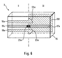
- the Microwave line 3 is a coaxial line. It shows one connected to the generator 1 first section I and a second section II connected to the antenna 7 on.
- the coaxial line has one in both sections Signal line 17g, 17h and a coaxially surrounding them Shield line 19g, 19h on.
- the plate 33 has two in the middle electrodes 35, 37 arranged opposite one another which form a first capacitor 21g through which the Signal lines 17g, 17h are electrically isolated.
- a second capacitor 23g is by two each on one outer edge of the insulating plate 33 each other oppositely arranged ring electrodes 39, 41 are formed. Through this, the shield lines 19g, 19h are galvanic Cut.
- the generator-facing in the middle of the plate 33 arranged electrode 35 is connected to the signal line 17g of the first section I and the antenna-facing electrode 37 is connected to the signal line 17h of the second section II the microwave line 3 connected. It is analog generator-facing ring electrode 39 with the shield line 17g of the first section I and an antenna-facing Ring electrode 41 is with the shield line 17h of the second Section II of the microwave line 3 connected.
- the first section I is for example one in the trade Available coaxial line, the outside of an insulation 25 is surrounded.
- the Signal line 17g of the first section I at the end e.g. provided with a hollow rivet 43.
- This has one tubular area on which the free end of the Tightly encloses signal line 17g and with it e.g. about a solder is electrically connected.
- a yourself radially outwardly extending shoulder of the hollow rivet 43 electrically conductive, e.g. also via a solder connection, with the generator-facing electrode 35 of the first Capacitor 21g connected.
- the microwave line 3 has a section without Isolation on. This section is in the shield wire 19g inserted a support tube 29. This is the reason Diameter of the antenna-facing end of the Shield line 19g widened slightly.
- the stripped Section of the microwave line is in a metal tube 27 arranged. This is put over the line end and then pressed, so that the end of the shield line 19g clamped between the metal tube 27 and the support tube 29 is. There is an electrically conductive connection between the support tube 29 and the shield line 19g.
- a metal sleeve 31 On the support tube 29 is in the direction facing the antenna a metal sleeve 31 with a slightly larger diameter molded. An annular disc-shaped face of the Metal sleeve 31 lies on the generator-facing Ring electrode 39 of the second capacitor 23g. It thus exists via the support tube 29 and the metal sleeve 31 an electrically conductive connection between the Shield cable 19g and the generator-facing Ring electrode 39.
- the one on the antenna-facing side of plate 33 arranged microwave line 3 can be just like that Microwave line 3 of the first section I a commercially available coaxial line. In this case their electrical connection to the electrode 37 and the Ring electrode 41 also in the manner described above respectively. The arrangement would then be symmetrical to the plate 33.
- the Section II of the microwave line 3 as a metal pin Signal line 17h on.
- This lies with a circular End face on the arranged in the middle of the plate 33 antenna-facing electrode 37.
- a shield cable 19h is a metal sleeve, e.g. from a stainless steel, provided with an annular disc-shaped end face rests on the antenna-facing ring electrode 41.
- an electrically conductive connection e.g. a Solder joint.
- the signal line 17h is e.g. electrically conductive with a arranged in the antenna 7 excitation pin connected.
- the plate 33 with the first and the second capacitor 21g, 23g as well as the adjacent areas in which the connection of the two sections I, II of Microwave line 3 to the first and second Capacitor 21g, 23g is made of an insulation 47, e.g. made of plastic, surrounded.
- an insulation 47 e.g. made of plastic
- the isolation 47 in an antenna facing Section an internal thread 49, by means of which they arranged on a on the shield line 19h External thread is screwed.
- Other types of attachment e.g. by means of snap or bayonet locks also possible.
- the shield line 19h of the second section II is with the Earth potential connected.
- the section facing the generator I the microwave line 3, however, is floating with the Microwave generator 1 connected.
- the described microwave lines 3 with galvanic Separation can also be added later existing level measuring device working with microwaves be introduced.
- the invention is also for those with microwaves working level gauges can be used, not only a single antenna serving as a transmitter and a receiver, but have two or more antennas. Each one the microwave line carrying the antennas would then be included one of the galvanic separations described above equip.
Abstract
Description
Die Erfindung betrifft ein mit Mikrowellen arbeitendes Füllstandsmeßgerät.The invention relates to a working with microwaves Level measuring device.
Mit Mikrowellen arbeitende Füllstandsmeßgeräte werden in fast allen Industriezweigen, z.B. in der Chemie und der Lebensmittelindustrie, eingesetzt. Sie dienen üblicherweise dazu Füllstände in Behältern zu überwachen und/oder anzuzeigen.Level measuring instruments working with microwaves are in almost all branches of industry, e.g. in chemistry and the Food industry. They usually serve to monitor fill levels in containers and / or display.
Bei der Füllstandsmessung werden Mikrowellen mittels einer Antenne zur Oberfläche eines Füllguts gesendet und an der Oberfläche reflektierte Echowellen empfangen. Es wird eine die Echoamplituden als Funktion der Entfernung darstellende Echofunktion gebildet, aus der das wahrscheinliche Nutzecho und dessen Laufzeit bestimmt werden. Aus der Laufzeit wird der Abstand zwischen der Füllgut-Oberfläche und der Antenne bestimmt.Microwave levels are measured using a Antenna sent to the surface of a product and on the Echo waves reflected from the surface received. It will be one representing the echo amplitudes as a function of distance Echo function formed from which the likely useful echo and its duration can be determined. The runtime becomes the distance between the product surface and the antenna certainly.
Es können alle bekannten verfahren angewendet werden, die es ermöglichen, verhältnismäßig kurze Entfernungen mittels reflektierter Mikrowellen zu messen. Die bekanntesten Beispiele sind das Pulsradar und das Frequenzmodulations-Dauerstrichradar (FMCW-Radar).All known methods can be used, the make it possible to use relatively short distances to measure reflected microwaves. The most popular Examples are pulse radar and frequency modulation continuous wave radar (FMCW radar).
Beim Pulsradar werden periodisch kurze Mikrowellen-Sendeimpulse, im folgenden als Wellenpakete bezeichnet, gesendet, die von der Füllgut-Oberfläche reflektiert und nach einer abstandsabhängigen Laufzeit wieder empfangen werden. Die empfangene Signalamplitude als Funktion der Zeit stellt die Echofunktion dar. Jeder Wert dieser Echofunktion entspricht der Amplitude eines in einem bestimmten Abstand von der Antenne reflektierten Echos.With pulse radar, short microwave transmission pulses are periodically hereinafter referred to as wave packets, sent, which is reflected by the product surface and received again after a distance-dependent runtime will. The received signal amplitude as a function of Time represents the echo function. Any value of this Echo function corresponds to the amplitude of one in one certain distance from the antenna reflected echoes.
Beim FMCW-Verfahren wird eine kontinuierliche Mikrowelle gesendet, die periodisch linear frequenzmoduliert ist, beispielsweise nach einer Sägezahnfunktion. Die Frequenz des empfangenen Echosignals weist daher gegenüber der Augenblicksfrequenz, die das Sendesignal zum Zeitpunkt des Empfangs hat, eine Frequenzdifferenz auf, die von der Laufzeit des Echosignals abhängt. Die Frequenzdifferenz zwischen Sendesignal und Empfangssignal, die durch Mischung beider Signale und Auswertung des Fourierspektrums des Mischsignals gewonnen werden kann, entspricht somit dem Abstand der reflektierenden Fläche von der Antenne. Ferner entsprechen die Amplituden der Spektrallinien des durch Fouriertransformation gewonnenen Frequenzspektrums den Echoamplituden. Dieses Fourierspektrum stellt daher in diesem Fall die Echofunktion dar.The FMCW process uses a continuous microwave sent, which is periodically linear frequency modulated, for example after a sawtooth function. The frequency of the received echo signal therefore points towards the Instantaneous frequency, which the transmission signal at the time of Has a frequency difference on the reception Duration of the echo signal depends. The frequency difference between transmit signal and receive signal by mixing both signals and evaluation of the Fourier spectrum of the Mixed signal can be obtained, corresponds to that Distance of the reflecting surface from the antenna. Further correspond to the amplitudes of the spectral lines of the Fourier transform obtained frequency spectrum Echo amplitudes. This Fourier spectrum therefore represents in in this case represents the echo function.
In der DE-A 42 41 910 ist ein mit Mikrowellen arbeitendes Füllstandsmeßgerät beschrieben welches umfaßt:
- einen Generator zur Erzeugung von Mikrowellen,
- mindestens eine Antenne zum Senden und Empfangen von Mikrowellen,
- eine Mikrowellenleitung,
- -- die vom Generator zur Antenne führt,
- -- die eine Signalleitung und mindestens eine Schirmleitung aufweist, und
- eine Empfangs- und Auswerteeinheit, die aus den empfangenen Mikrowellen einen Füllstand bestimmt und die ein Ausgangssignal erzeugt, das dem Füllstand entspricht.
- a generator for generating microwaves,
- at least one antenna for transmitting and receiving microwaves,
- a microwave line,
- - which leads from the generator to the antenna,
- - Which has a signal line and at least one shield line, and
- a receiving and evaluation unit which determines a fill level from the microwaves received and which generates an output signal which corresponds to the fill level.
Aus sicherheitstechnischen Gründen ist es insb. beim Einsatz von Füllstandsmeßgeräten in Umgebungen in denen Explosionsgefahr besteht erforderlich eine galvanische Trennung zwischen dem Meßgerät und dem Prozeß, z.B. dem Innenraum eines Behälters, dessen Füllstand zu messen ist, anzubringen. Hierdurch wird eine Funkenbildung vermieden. Die Anforderungen, die an galvanische Trennungen in bestimmten Anwendungen gestellt werden, können von Land zu Land verschieden sein. Sie sind üblicherweise in Normen, z.B. der Europäischen Industrienorm EN 50020, angegeben.For security reasons, it is especially with Use of level gauges in environments in which There is a risk of explosion with a galvanic one Separation between the measuring device and the process, e.g. the Interior of a container whose level is to be measured, to attach. This prevents sparking. The requirements for galvanic isolation in Certain applications can be made from country to country Country may be different. They are usually in standards, e.g. the European industrial standard EN 50020.
Bei handelsüblichen Meßgeräten erfolgt die galvanische Trennung in einem Eingangsmodul. Es werden sämtliche nach außen bestehenden elektrischen Verbindungen, d.h. üblicherweise mindestens zwei Versorgungsleitungen, mindestens eine Meßsignalleitung und eine Leitung über die Information über Sendezeitpunkte von Mikrowellenpulsen beim Pulsradar bzw. über einen Periodenbeginn beim FMCW-Radar übertragen werden, galvanisch getrennt.In the case of commercially available measuring devices, the galvanic is carried out Separation in an input module. It will all follow external electrical connections, i.e. usually at least two supply lines, at least one measurement signal line and a line over the Information on times of transmission of microwave pulses at Pulse radar or over a period beginning with the FMCW radar are transmitted, galvanically isolated.
Zur galvanischen Trennung der Versorgungsleitungen werden z.B. Gleichstrom-Gleichstrom-Wandler und zur galvanischen Trennung von Meßsignalleitungen z.B. Optokoppler eingesetzt. For electrical isolation of the supply lines e.g. DC-DC converter and for galvanic Separation of measuring signal lines e.g. Optocoupler used.
Aufgrund der Anzahl der Leitungen und deren Beschaffenheit sind nicht nur mehrere sondern auch relativ teure Bauteile zur galvanischen Trennung erforderlich.Due to the number of lines and their nature are not only several, but also relatively expensive components required for electrical isolation.
Es ist eine Aufgabe der Erfindung, ein mit Mikrowellen arbeitendes Füllstandsmeßgerät anzugeben, bei dem eine galvanische Trennung mittels einer sehr geringen Anzahl von kostengünstigen Bauteilen erfolgt.It is an object of the invention to use microwaves Specify working level meter, in which a galvanic isolation using a very small number of inexpensive components.
Hierzu besteht die Erfindung in einem mit Mikrowellen arbeitenden Füllstandsmeßgerät, welches umfaßt:
- einen Generator zur Erzeugung von Mikrowellen,
- mindestens eine Antenne zum Senden und Empfangen von Mikrowellen,
- eine Mikrowellenleitung,
- -- die vom Generator zur Antenne führt und
- -- die eine Signalleitung und mindestens eine Schirmleitung aufweist,
- einen in die Signalleitung eingefügten ersten Kondensator zur galvanische Trennung der Signalleitung,
- einen in jede Schirmleitung eingefügten zweiten Kondensator zur galvanische Trennung der jeweiligen Schirmleitung, und
- eine Empfangs- und Auswerteeinheit, die aus den empfangenen Mikrowellen einen Füllstand bestimmt und die ein Ausgangssignal erzeugt, das dem Füllstand entspricht.
- a generator for generating microwaves,
- at least one antenna for transmitting and receiving microwaves,
- a microwave line,
- - Which leads from the generator to the antenna and
- which has a signal line and at least one shield line,
- a first capacitor inserted in the signal line for galvanic isolation of the signal line,
- a second capacitor inserted in each shield line for galvanic isolation of the respective shield line, and
- a receiving and evaluation unit which determines a fill level from the microwaves received and which generates an output signal which corresponds to the fill level.
Gemäß einer ersten Ausgestaltung ist die Mikrowellenleitung eine auf einer ersten Seite einer Platine angeordnete Koplanar-Leitung ist, bei der zu jeder Seite der Signalleitung je eine Schirmleitung angeordnet ist, und der erste und die zweiten Kondensatoren sind auf der ersten Seite der Platine angeordnete Bauteile.According to a first embodiment, the microwave line one arranged on a first side of a circuit board The coplanar line is the one on each side of the Signal line a shield line is arranged, and the first and second capacitors are on the first Components arranged on the side of the circuit board.
Gemäß einer zweiten Ausgestaltung ist die Mikrowellenleitung eine auf einer Platine angeordnete Mikrostreifenleitung, bei der auf einer ersten Seite der Platine eine Signalleitung und ein erster Kondensator angeordnet sind und bei der auf einer zweiten der ersten Seite gegenüberliegenden Seite der Platine mindestens eine Schirmleitung und mindestens ein zweiter Kondensator angeordnet ist.According to a second embodiment, the Microwave line one arranged on a circuit board Microstrip line, on which on a first side of the Circuit board a signal line and a first capacitor are arranged and in which on a second of the first Side opposite side of the board at least one Shield line and at least one second capacitor is arranged.
Gemäß einer dritten Ausgestaltung ist die Mikrowellenleitung eine auf einer Platine angeordnete Koplanar-Leitung, bei der zu jeder Seite der Signalleitung je eine Schirmleitung angeordnet ist, die einen ersten mit dem Generator verbundenen Abschnitt aufweist, in dem die Signalleitung und die Schirmleitungen auf einer ersten Seite der Platine angeordnet sind, und die einen zweiten mit der Antenne verbundenen Abschnitt aufweist, in dem die Signalleitung und die Schirmleitungen auf einer zweiten der ersten Seite gegenüberliegenden Seite der Platine angeordnet sind, wobei der erste und der zweite Abschnitt der Mikrowellenleitung überlappen, wobei der erste Kondensator durch überlappende Bereiche der Signalleitungen des ersten und des zweiten Abschnitts und einen dazwischen befindlichen Bereich der Platine gebildet ist und wobei die zweiten Kondensatoren durch überlappende Bereiche der Schirmleitungen des ersten und des zweiten Abschnitts und dazwischen befindliche Bereiche der Platine gebildet sind. According to a third embodiment, the microwave line a coplanar line arranged on a circuit board, one on each side of the signal line Shield line is arranged, the first with the Generator connected section in which the Signal line and the shield lines on a first Side of the board are arranged, and the second section connected to the antenna, in which the Signal line and the shield lines on a second of the first side opposite side of the board are arranged, the first and the second section overlap the microwave line, the first Capacitor through overlapping areas of the signal lines of the first and second sections and one in between located area of the board is formed and wherein the second capacitors through overlapping areas of the Shield lines of the first and second sections and Intermediate areas of the board are formed.
Gemäß einer vierten Ausgestaltung weist die Mikrowellenleitung einen ersten Abschnitt auf, in dem die Mikrowellenleitung eine auf einer Platine angeordnete Koplanar-Leitung ist, bei der auf einer ersten Seite der Platine eine Signalleitung und zu jeder Seite der Signalleitung je eine Schirmleitung angeordnet ist, und sie weist einen einen zweiten Abschnitt auf, in dem die Mikrowellenleitung eine Mikrostreifenleitung ist, die eine auf der ersten Seite der Platine verlaufende Signalleitung und mindestens eine auf einer zweiten der ersten Seite gegenüberliegenden Seite der Platine angeordnete Schirmleitung aufweist, wobei der erste und der zweite Abschnitt der Mikrowellenleitung überlappen, wobei der erste Kondensator auf der ersten Seite der Platine angeordnet ist, wobei die zweiten Kondensatoren durch überlappende Bereiche der Schirmleitungen des ersten und des zweiten Abschnitts und dazwischen befindliche Bereiche der Platine gebildet sind, und wobei entweder der erste Abschnitt mit der Antenne und der zweite Abschnitt mit dem Generator oder umgekehrt der zweite Abschnitt mit der Antenne und der erste Abschnitt mit dem Generator verbunden ist.According to a fourth embodiment, the microwave line a first section in which the Microwave line one arranged on a circuit board Coplanar line is, on the first side of the Board a signal line and to each side of the Signal line one shield line is arranged, and they has a second section in which the Microwave line is a microstrip line, the one signal line running on the first side of the board and at least one on a second of the first page opposite side of the board Has shield line, the first and the second Section of the microwave line overlap, the first capacitor on the first side of the board is arranged, the second capacitors through overlapping areas of the shield lines of the first and of the second section and areas in between the board are formed, and being either the first Section with the antenna and the second section with the Generator or vice versa the second section with the Antenna and the first section connected to the generator is.
Gemäß einer fünften Ausgestaltung ist die Mikrowellenleitung eine Koaxialleitung,die einen mit dem Generator verbundenen ersten Abschnitt und einen mit der Antenne verbundenen zweiten Abschnitt aufweist. Zwischen dem ersten und dem zweiten Abschnitt ist eine Platte aus einem Isolator angeordnet, der erste Kondensator weist zwei jeweils in der Mitte der Platte einander gegenüberliegend angeordnete Elektroden auf, von denen eine generatorzugewandte Elektrode mit der Signalleitung des ersten Abschnitts und eine antennen-zugewandte Elektrode mit der Signalleitung des zweiten Abschnitts der Mikrowellenleitung verbunden ist, und der zweite Kondensator weist zwei jeweils auf einem äußeren Rand der Platte einander gegenüberliegend angeordnete Ringelektroden auf, von denen eine generator-zugewandte Ringelektrode mit der Schirmleitung des ersten Abschnitts und eine antennenzugewandte Ringelektrode mit der Schirmleitung des zweiten Abschnitts der Mikrowellenleitung verbunden ist.According to a fifth embodiment, the microwave line a coaxial line, one with the generator connected first section and one with the antenna connected second section. Between the first and the second section is a plate of one Insulator arranged, the first capacitor has two opposite each other in the middle of the plate arranged electrodes, one of which facing the generator Electrode with the signal line of the first Section and an antenna-facing electrode with the Signal line of the second section of the microwave line is connected, and the second capacitor has two each on an outer edge of the plate oppositely arranged ring electrodes, of which a generator-facing ring electrode with the Shield line of the first section and an antenna facing Ring electrode with the shield line of the second Section of the microwave line is connected.
Gemäß einer Weiterbildung der fünften Ausgestaltung ist ein zwischen der Schirmleitung und der Signalleitung des zweiten Abschnitts der Mikrowellenleitung bestehender Hohlraum mit einem Isolator, insb. mit Glas, ausgefüllt.According to a development of the fifth embodiment, a between the shield line and the signal line of the second section of the microwave line existing Cavity filled with an insulator, especially with glass.
Ein Vorteil der Erfindung besteht darin, daß die galvanische Trennung hochfrequenz-seitig, also zwischen dem Generator und der Antenne erfolgt. An diesem Ort ist nur eine einzige Leitung, nämlich die Mikrowellenleitung, galvanisch zu trennen. Hierdurch ist der Einsatz von im Vergleich zu Gleichstrom-Gleichstromwandlern oder Optokopplern kostengünstigen Kondensatoren möglich.An advantage of the invention is that the galvanic isolation on the radio frequency side, i.e. between the Generator and the antenna is done. In this place is only a single line, namely the microwave line, to be galvanically separated. As a result, the use of im Comparison to DC-DC converters or Optocouplers inexpensive capacitors possible.
Ein weiterer Vorteil besteht darin, daß vorhandene Füllstandsmeßgeräte, die bisher nicht in explosionsgefährdeten Bereichen eingesetzt werden konnten, mit einer galvanischen Trennung nachgerüstet werden können. Another advantage is that existing ones Level gauges that have not previously been used in potentially explosive atmospheres Areas could be used with a galvanic isolation can be retrofitted.
Die Erfindung und weitere Vorteile werden nun anhand der Figuren der Zeichnung, in denen fünf Ausführungsbeispiele dargestellt sind, näher erläutert; gleiche Elemente sind in den Figuren mit gleichen Bezugszeichen versehen.
- Fig. 1
- zeigt schematisch ein mit Mikrowellen arbeitendendes Füllstandsmeßgerät;
- Fig. 2
- zeigt ein Ausführungsbeispiel der in Fig. 1 dargestellten Mikrowellenleitung, bei dem die Mikrowellenleitung eine auf einer Platine angeordnete Koplanar-Leitung ist, die mittels auf der Platine angeordneter Kondensatoren galvanisch getrennt ist;
- Fig. 3
- zeigt ein Ausführungsbeispiel der in Fig. 1 dargestellten Mikrowellenleitung bei dem die Mikrowellenleitung eine auf einer Platine angeordnete Mikrostreifenleitung ist, die mittels auf der Platine angeordneter Kondensatoren galvanisch getrennt ist;
- Fig. 4
- zeigt ein weiteres Ausführungsbeispiel der in Fig. 1 dargestellten Mikrowellenleitung, bei der ein erster Abschnitt der Mikrowellenleitung eine auf einer ersten Seite der Platine angeordnete Koplanar-Leitung ist und bei der ein zweiter Abschnitt eine auf einer zweiten Seite der Platine angeordnete Koplanar-Leitung ist;
- Fig. 5
- zeigt einen Schnitt durch die Mikrowellenleitung von Fig. 3;
- Fig. 6
- zeigt ein weiteres Ausführungsbeispiel der in Fig. 1 dargestellten Mikrowellenleitung bei dem ein erster Abschnitt der Mikrowellenleitung eine auf einer Platine angeordnete Koplanar-Leitung und ein zweiter Abschnitt eine auf derselben Platine angeordnete Mikrostreifenleitung ist; und
- Fig. 7
- zeigt ein Ausführungsbeispiel der in Fig. 1 dargestellten Mikrowellenleitung bei dem die Mikrowellenleitung eine Koaxialleitung ist, in die ein Kondensator eingefügt ist.
- Fig. 1
- schematically shows a level measuring device working with microwaves;
- Fig. 2
- shows an embodiment of the microwave line shown in Figure 1, in which the microwave line is a coplanar line arranged on a circuit board, which is galvanically isolated by means of capacitors arranged on the circuit board;
- Fig. 3
- shows an embodiment of the microwave line shown in Figure 1 in which the microwave line is a microstrip line arranged on a circuit board, which is galvanically isolated by means of capacitors arranged on the circuit board;
- Fig. 4
- 1 shows a further embodiment of the microwave line shown in FIG. 1, in which a first section of the microwave line is a coplanar line arranged on a first side of the circuit board and in which a second section is a coplanar line arranged on a second side of the circuit board;
- Fig. 5
- shows a section through the microwave line of Fig. 3;
- Fig. 6
- 1 shows a further exemplary embodiment of the microwave line shown in FIG. 1, in which a first section of the microwave line is a coplanar line arranged on a circuit board and a second section is a microstrip line arranged on the same circuit board; and
- Fig. 7
- shows an embodiment of the microwave line shown in Fig. 1 in which the microwave line is a coaxial line in which a capacitor is inserted.
In Fig. 1 ist ein mit Mikrowellen arbeitendes Füllstandsmeßgerät schematisch dargestellt. Die Mikrowellen werden von einem Generator 1 erzeugt. Dies ist beispielsweise ein Pulsradar-Gerät, ein FMCW-Gerät oder ein kontinuierlich schwingender Mikrowellen-Oszillator, der ein Sendesignal erzeugt.In Fig. 1 is a level measuring device working with microwaves shown schematically. The microwaves are generated by a generator 1. For example, this is a Pulse radar device, an FMCW device or a continuous vibrating microwave oscillator that sends a signal generated.
Das Sendesignal wird über eine Sende-Empfangsweiche 5, z.B.
einen Richtkoppler, zu einer oberhalb eines Behälters 9
angeordneten Antenne 7 übertragen. Von der Sende-Empfangsweiche
5 führt eine Mikrowellenleitung 3 zur
Antenne 7. Dies ist beispielsweise eine auf einer Platine
angeordnete Mikrostreifenleitung, eine Koplanar-Leitung,
eine Kombination aus Mikrostreifen- und Koplanar-Leitung
oder eine Koaxialleitung. The transmission signal is transmitted via a
Eine Koplanar-Leitung weist drei parallel zueinander auf einer Platine aufgebrachte planare Leitungsstrukturen auf, von denen eine mittlere eine Signalleitung ist und zwei äußere jeweils Schirmleitungen sind.A coplanar line has three parallel to each other a planar line structure applied to a circuit board, a middle one is a signal line and two outer shield cables are in each case.
Eine Mikrostreifenleitung weist eine auf einer ersten Seite einer Platine angeordnete planare Leitungsstruktur auf, die als Signalleitung dient. Auf einer der ersten Seite gegenüberliegenden Seite der Platine ist eine weitere, planare Leitungsstruktur aufgebracht, die üblicherweise deutlich breiter als die Signalleitung ist und als Schirmleitung dient.A microstrip line has one on a first side a planar line structure arranged on a circuit board serves as a signal line. On one of the first pages opposite side of the board is another one planar line structure applied, which is usually is significantly wider than the signal line and as Shield wire is used.
Der Behälter 9 enthält ein Füllgut, dessen Füllstand zu
bestimmen ist. Von der Antenne 7 ausgesendete Mikrowellen
werden an der Oberfläche des Füllguts reflektiert und die
Echowellen werden von der Antenne 7 aufgenommen. Ein
entsprechendes Empfangssignal ist über die Sende-Empfangsweiche
5 einer Empfangs- und Auswerteschaltung 11
zugeführt. Über dieselbe Sende-Empfangsweiche 5 ist das vom
Generator 1 erzeugte Sendesignal der Empfangs- und
Auswerteschaltung 11 zugeführt. Aus den beiden Signalen
wird der Abstand zwischen Antenne 7 und Füllgutoberfläche
bestimmt. Da der Abstand zwischen der Antenne 7 und dem
Behälterboden bekannt ist, ergibt sich hieraus direkt der
zu messende Füllstand.The container 9 contains a filling material whose level is too
determine is. Microwaves emitted by the
Die Antenne 7 ist z.B. ein aus einem elektrisch leitenden
Material, z.B. aus Aluminium oder einem Edelstahl,
bestehender Hornstrahler oder eine stabförmige Antenne aus
einem Dielektrikum, z.B. aus Polytetrafluorethylen (PTFE). The
Die letztgenannte Antennenform wird häufig auch als dielektrischer Stielstrahler bezeichnet.The latter antenna form is often also called dielectric stem radiator called.
Erfindungsgemäß weist die Mikrowellenleitung 3 eine
galvanische Trennung 13 auf. In den Figuren 2 bis 7 sind
fünf Ausführungsbeispiele dargestellt. Bei allen
Ausführungsbeispielen weist die Mikrowellenleitung 3
jeweils eine Signalleitung und mindestens eine
Schirmleitung auf. In die Signalleitung ist jeweils ein
erster Kondensator zur galvanische Trennung der
Signalleitung eingefügt und in jede Schirmleitung ist
jeweils ein zweiter Kondensator zur galvanische Trennung
der jeweiligen Schirmleitung eingefügt.According to the invention, the
Die Kondensatoren haben eine mechanisch feste Isolation, sie werden im Fehlerfall, z.B. bei hoher Überlast, hochohmig und weisen eine hohe Spannungsfestigkeit, z.B. von 500 V, auf.The capacitors have mechanically strong insulation, in the event of an error, e.g. with high overload, high resistance and have a high dielectric strength, e.g. from 500 V to.
In dem in Fig. 2 dargestellten Ausführungsbeispiel ist die
Mikrowellenleitung 3 eine auf einer ersten Seite einer
Platine 15 angeordnete Koplanar-Leitung. Eine der ersten
Seite gegenüberliegende zweite Seite der Platine 15 ist
entweder frei oder mit einer metallischen Beschichtung
versehen und mit einem Bezugspotential, z.B. Masse,
verbunden. Die Koplanar-Leitung besteht aus drei parallel
zueinander verlaufenden auf die Platine 15 aufgebrachten
planaren Leitungsstrukturen. Die mittlere Leitung dient als
Signalleitung 17a und zu beiden Seiten der Signalleitung
17a verläuft jeweils eine Schirmleitung 19a. In the embodiment shown in Fig. 2, the
In die Signalleitung 17a ist auf der ersten Seite der
Platine 15 ein erster Kondensator 21a eingefügt, durch den
eine galvanische Trennung der Signalleitung 17a erfolgt.
In die Schirmleitungen 19a sind auf der ersten Seite der
Platine 15 zweite Kondensatoren 23a eingefügt, durch die
eine galvanische Trennung der Schirmleitungen 19a erfolgt.
Die Kondensatoren 21a, 23a sind z.B. handelsübliche für
Mikrowellen geeignete auf einer Platine anbringbare auch
als Surface-Mounted-Device bezeichnete Bauteile.In the
Durch die ersten und zweiten Kondensatoren 21a, 23a ist die
Mikrowellenleitung 3 in einen generator-zugewandten
Abschnitt I und einen antennen-zugewandten Abschnitt II
unterteilt. Auf der generator-zugewandten Seite sind die
Signalleitung 17a und Schirmleitungen 19a erdfrei mit dem
Generator 1 verbunden. Durch die Erdfreiheit sind
Potentialausgleichsleitungen, z.B. von einer Versorgung zum
Meßgerät, weitgehend überflüssig. Auf der antennenzugewandten
Seite ist die Signalleitung 17a mit einem in
der Antenne 7 angeordneten in der Figur nicht dargestellten
Erregerelement verbunden. Das Erregerelement dient dazu
Mikrowellen von der Mikrowellenleitung 3 in die Antenne 7
einzukoppeln und umgekehrt von der Antenne 7 aufgenommene
Mikrowellen in die Mikrowellenleitung 3 einzukoppeln. Die
Schirmleitungen 19a des antennen-zugewandten Abschnitts II
sind mit Erdpotential verbunden. Ist die Antenne 7 ein
dielektrischer Stielstrahler, so ist dessen metallische
Befestigung mit dem Erdpotential verbunden. Ist die Antenne
7 ein Hornstrahler, so ist das metallische Horn mit dem
Erdpotential verbunden. Due to the first and
Fig. 3 zeigt ein weiteres Ausführungsbeispiel der in Fig. 1
dargestellten Mikrowellenleitung 3. Als Mikrowellenleitung
3 dient hier eine auf der Platine 15 angeordnete
Mikrostreifenleitung. Eine Signalleitung 17b ist auf einer
ersten Seite der Platine 15 angeordnet. Auf der der ersten
Seite gegenüberliegenden zweiten Seite der Platine 15 ist
eine Schirmleitung 19b angeordnet. Die Mikrowellenleitung 3
ist auch hier durch erste und zweite Kondensatoren 21b, 23b
in zwei Abschnitte I, II unterteilt, nämlich einen ersten
mit dem Generator 1 verbundenen Abschnitt I und einen
zweiten mit der Antenne 7 verbundenen Abschnitt II. Wie bei
dem Ausführungsbeispiel von Fig. 2 sind die Kondensatoren
21b, 23b auf der Platine 15 angebracht und bewirken eine
galvanische Trennung der Signalleitung 17b und der
Schirmleitung 19b.FIG. 3 shows a further exemplary embodiment of that in FIG. 1
shown
Fig. 4 zeigt ein weiteres Ausführungsbeispiel bei dem die
Mikrowellenleitung 3 eine auf einer Platine 15 angeordnete
Koplanar-Leitung ist. Die Mikrowellenleitung 3 ist auch
hier durch erste und zweite Kondensatoren 21c, 23c in zwei
Abschnitte I, II unterteilt, nämlich einen ersten mit dem
Generator 1 verbundenen Abschnitt I und einen zweiten mit
der Antenne 7 verbundenen Abschnitt II.Fig. 4 shows a further embodiment in which the
In dem ersten Abschnitt I sind eine Signalleitung 17c und
zwei Schirmleitungen 19c auf der ersten Seite der Platine
15 angeordnet. In dem zweiten Abschnitt II sind eine
Signalleitung 17d und zwei Schirmleitungen 19d auf der
zweiten der ersten Seite gegenüberliegenden Seite der
Platine 15 angeordnet. Die beiden Abschnitte I und II
überlappen. Die antennen-zugewandten Enden der
Signalleitung 17c und der Schirmleitungen 19c des ersten
Abschnitts I sind jeweils über den generator-zugewandten
Enden der entsprechenden Signalleitung 17d bzw.
Schirmleitung 19d des zweiten Abschnitts II angeordnet. Die
überlappenden Bereiche schließen jeweils einen dazwischen
befindlichen Bereich der Platine 15 ein.In the first section I are a
Der erste Kondensator 21c, durch den die Signalleitungen
17c, 17d miteinander galvanisch getrennt verbunden sind ist
durch die überlappenden Bereiche der Signalleitungen 17c,
17d des ersten und des zweiten Abschnitts I, II und einen
dazwischen befindlichen Bereich der Platine 15 gebildet.The
Die zweiten Kondensatoren 23c, durch die die
Schirmleitungen 19c, 19d miteinander galvanisch getrennt
verbunden sind, sind durch die überlappenden Bereiche der
jeweiligen Schirmleitungen 19c, 19d des ersten und des
zweiten Abschnitts I, II und die dazwischen befindlichen
Bereiche der Platine 15 gebildet.The
Fig. 5 zeigt einen Schnitt durch die Mikrowellenleitung 3
von Fig. 4, aus dem die Überlappung der Abschnitte I und II
und die dadurch gebildeten Kondensatoren, am Beispiel der
Schirmleitungen 19c, 19d und des zweiten Kondesators 23c,
gezeigt sind.5 shows a section through the
In Abhängigkeit von den Eigenschaften, insb. der Frequenz bzw. des Frequenzspektrums, der zu übertragenden Mikrowellen kann die Geometrie der Enden der Signalleitungen und der Schirmleitungen besonders angepaßt sein. So lassen sich z.B. breitbandige Übertragungseigenschaften erzielen, indem die Enden vorzugsweise deutlich breiter als die eigentlichen Leitungen ausgebildet sind und die Form von Viertelkreises aufweisen. Auch ist durch diese Geometrie der Impedanzsprung an dem Übergang weniger groß und es wird somit weniger Mikrowellenstrahlung reflektiert.Depending on the properties, especially the frequency or the frequency spectrum of those to be transmitted The geometry of the ends of the microwaves Signal lines and the shield lines specially adapted be. For example, broadband transmission characteristics achieve by preferring the ends significantly wider than the actual lines are and have the shape of a quarter circle. Is too through this geometry the impedance jump at the transition less large and therefore less microwave radiation reflected.
Ein Vorteil der letztbeschriebenen Mikrowellenleitung 3
ist, daß keine zusätzlichen Kondensatoren erforderlich
sind, sondern stattdessen die ohnehin vorhandene Platine 15
genutzt wird.An advantage of the last described
Auf der generator-zugewandten Seite sind die Signalleitung
17c und Schirmleitungen 19c erdfrei mit dem Generator 1
verbunden. Auf der antennen-zugewandten Seite ist die
Signalleitung 17d mit einem in der Antenne 7 angeordneten
in der Figur nicht dargestellten Erregerelement verbunden.
Auch hier dient das Erregerelement dazu Mikrowellen von der
Mikrowellenleitung 3 in die Antenne 7 einzukoppeln und
umgekehrt von der Antenne 7 aufgenommene Mikrowellen in die
Mikrowellenleitung 3 einzukoppeln. Die Schirmleitungen 19d
des antennen-zugewandten Abschnitts II sind mit
Erdpotential verbunden. Ist die Antenne 7 ein
dielektrischer Stielstrahler, so ist dessen metallische
Befestigung mit dem Erdpotential verbunden. Ist die Antenne
7 ein Hornstrahler, so ist das metallische Horn mit dem
Erdpotential verbunden.The signal line is on the side facing the
Bei dem in Fig. 6 dargestellten Ausführungsbeispiel weist
die Mikrowellenleitung 3 einen ersten mit dem Generator 1
verbundenen Abschnitt I auf, der als Koplanar-Leitung
ausgebildet ist. Ein zweiter mit der Antenne 7 verbundener
Abschnitt II der Mikrowellenleitung 3 ist als
Mikrostreifenleitung ausgebildet. Beide Abschnitte I, II
sind auf derselben Platine 15 angeordnet.In the embodiment shown in Fig. 6 points
the
Eine Signalleitung 17e ist sowohl im ersten als auch im
zweiten Abschnitt I, II auf der ersten Seite der Platine 15
angeordnet. Im ersten Abschnitt I ist zu jeder Seite der
Signalleitung 17e je eine Schirmleitung 19e angeordnet.A
Auf der zweiten Seite der Platine 15 ist in dem zweiten
Abschnitt II eine Schirmleitung 19f angeordnet. Diese
besteht aus einem metallisch beschichteten Bereich der
zweiten Seite der Platine 15. Der erste und der zweite
Abschnitt I und II überlappen. Ein antennen-zugewandtes
Ende jeder der auf der ersten Seite der Platine 15
angeordneten Schirmleitungen 19e überdeckt somit den
metallisch beschichteten Bereich, der die Schirmleitung 19f
des zweiten Abschnitts II bildet.On the second side of the
Anstelle einer einzigen großflächigen Schirmleitung 19f
können selbstverständlich auch zwei oder mehr einzelne z.B.
streifenförmige Schirmleitungen auf der zweiten Seite der
Platine 15 aufgebracht sein. Es muß lediglich gewährleistet
sein, daß ein ausreichender Überlapp zwischen den
Schirmleitungen 19e des ersten Abschnitts I und der bzw.
den Schirmleitungen des zweiten Abschnitts II besteht.Instead of a single large-
Der erste Kondensator 21e ist auf der ersten Seite der
Platine 15 in die Signalleitung 17e eingefügt. Die zweiten
Kondensatoren 23e sind durch die überlappenden Bereiche der
Schirmleitungen 19e des ersten und 19f des zweiten
Abschnitts II und dazwischen befindliche Bereiche der
Platine 15 gebildet.The
Die antennen-zugewandten Enden der Schirmleitungen 19e sind gegenüber den eigentlichen Schirmleitungen 19e verbreitert und weisen die Form eines Viertelkreises auf. Hierdurch wird erreicht, daß der Impedanzsprung für Mikrowellenstrahlung an dem Übergang vom ersten zum zweiten Abschnitt weniger groß ist und somit weniger Mikrowellenstrahlung reflektiert wird. Auch wird der Frequenzbereich, indem günstige Übertragungseigenschaften vorliegen durch diese Geometrie verbreitert. Andere Geometrien der Enden, z.B. solche, die an eine spezielle zu verwendende Mikrowellenstrahlung angepaßt sind, sind ebenfalls einsetzbar.The ends of the shield lines 19e facing the antenna are widened compared to the actual shield lines 19e and have the shape of a quarter circle. Hereby is achieved that the impedance jump for microwave radiation at the transition from the first to the second section is less large and therefore less microwave radiation is reflected. Also the frequency range by this provides favorable transmission properties Geometry broadened. Other end geometries, e.g. those designed for a special use Microwave radiation are also adjusted applicable.
Durch die ersten und zweiten Kondensatoren 21e, 23e ist die
Mikrowellenleitung 3 in einen generator-zugewandten
Abschnitt I und einen antennen-zugewandten Abschnitt II
unterteilt. Auf der generator-zugewandten Seite sind die
Signalleitung 17e und Schirmleitungen 19e erdfrei mit dem
Generator 1 verbunden. Auf der antennen-zugewandten Seite
ist die Signalleitung 17e genau wie bei den vorgenannten
Ausführungsbeispielen mit einem in der Antenne 7
angeordneten in der Figur nicht dargestellten
Erregerelement verbunden.Due to the first and
Selbstverständlich kann die beschriebene Mikrowellenleitung
3 von Fig. 6 auch in umgekehrter Orientierung verwendet
werden. Entsprechend wäre dann der als Koplanar-Leitung
ausgebildete erste Abschnitt I mit der Antenne 7 und der
als Mikrostreifenleitung ausgebildete zweite Abschnitt II
erdfrei mit dem Generator 1 zu verbinden.Of course, the described
Bei dem in Fig. 7 dargestellten Ausführungsbeispiel ist die
Mikrowellenleitung 3 eine Koaxialleitung. Sie weist einen
mit dem Generator 1 verbundenen ersten Abschnitt I und
einen mit der Antenne 7 verbundenen zweiten Abschnitt II
auf. In beiden Abschnitten weist die Koaxialleitung eine
Signalleitung 17g, 17h und eine diese koaxial umgebende
Schirmleitung 19g, 19h auf.In the embodiment shown in Fig. 7 is the
Zwischen dem ersten und dem zweiten Abschnitt I, II ist
eine Platte 33 aus einem Isolator, z.B. aus Aluminiumoxid,
angeordnet. Die Platte 33 weist zwei in deren Mitte
einander gegenüberliegend angeordnete Elektroden 35, 37
auf, die einen ersten Kondensator 21g bilden, durch den die
Signalleitungen 17g, 17h galvanisch getrennt sind. Ein
zweiter Kondensator 23g ist durch zwei jeweils auf einem
äußeren Rand der isolierenden Platte 33 einander
gegenüberliegend angordnete Ringelektroden 39, 41 gebildet.
Durch diesen sind die Schirmleitungen 19g, 19h galvanisch
getrennt.Between the first and second sections I, II
a
Die generator-zugewandte in der Mitte der Platte 33
angeordnete Elektrode 35 ist mit der Signalleitung 17g des
ersten Abschnitts I und die antennen-zugewandte Elektrode
37 ist mit der Signalleitung 17h des zweiten Abschnitts II
der Mikrowellenleitung 3 verbunden. Analog ist die
generator-zugewandte Ringelektrode 39 mit der Schirmleitung
17g des ersten Abschnitts I und eine antennen-zugewandte
Ringelektrode 41 ist mit der Schirmleitung 17h des zweiten
Abschnitts II der Mikrowellenleitung 3 verbunden.The generator-facing in the middle of the
Der erste Abschnitt I ist beispielsweise eine im Handel
erhältliche Koaxialleitung, die außen von einer Isolation
25 umgeben ist.The first section I is for example one in the trade
Available coaxial line, the outside of an
Innenleiter von handelsüblichen Koaxialleitungen weisen
einen geringen Durchmesser auf. Aus diesem Grund ist die
Signalleitung 17g des ersten Abschnitts I endseitig z.B.
mit einem Hohlniet 43 versehen. Dieser weist einen
rohrfömigen Bereich auf, der das freie Ende der
Signalleitung 17g eng umschließt und mit dieser z.B. über
eine Lötung elektrisch leitend verbunden ist. Eine sich
radial nach außen erstreckende Schulter des Hohlniet 43 ist
elektrisch leitend, z.B. ebenfalls über eine Lötverbindung,
mit der generator-zugewandten Elektrode 35 des ersten
Kondensators 21g verbunden.Point the inner conductor of commercially available coaxial cables
a small diameter. For this reason, the
An dem antennen-zugewandten Ende des ersten Abschnitts I
weist die Mikrowellenleitung 3 einen Abschnitt ohne
Isolation auf. In diesen Abschnitt ist in die Schirmleitung
19g ein Stützrohr 29 eingesteckt. Dadurch bedingt ist der
Durchmesser des antennen-zugewandten Endes der
Schirmleitung 19g geringfügig aufgeweitet. Der abisolierte
Abschnitt der Mikrowellenleitung ist in einem Metallrohr 27
angeordnet. Dieses ist über das Leitungsende gestülpt und
anschießend verpreßt, so daß das Ende der Schirmleitung 19g
zwischen dem Metallrohr 27 und dem Stützrohr 29 eingespannt
ist. Es besteht eine elektrisch leitende Verbindung
zwischen dem Stützrohr 29 und der Schirmleitung 19g. At the antenna-facing end of the first section I
the
An das Stützrohr 29 ist in antennen-zugewandter Richtung
eine Metallhülse 31 mit geringfügig größerem Durchmesser
angeformt. Eine ringscheibenförmige Stirnfläche der
Metallhülse 31 liegt auf der generator-zugewandten
Ringelektrode 39 des zweiten Kondensators 23g auf. Es
besteht somit über das Stützrohr 29 und die Metallhülse 31
eine elektrisch leitende Verbindung zwischen der
Schirmleitung 19g und der generator-zugewandten
Ringelektrode 39.On the
Die auf der antennen-zugewandten Seite der Platte 33
angeordnete Mikrowellenleitung 3 kann genau wie die
Mikrowellenleitung 3 des ersten Abschnitts I eine
handelsübliche Koaxialleitung sein. In diesem Fall kann
deren elektrischer Anschluß an die Elektrode 37 und die
Ringelektrode 41 ebenfalls auf die oben beschriebene Weise
erfolgen. Die Anordnung wäre dann symmetrisch zu der Platte
33.The one on the antenna-facing side of
Bei dem in Fig. 7 gezeigten Ausführungsbeispiel weist der
Abschnitt II der Mikrowellenleitung 3 einen Metallstift als
Signalleitung 17h auf. Diese liegt mit einer kreisförmigen
Stirnfläche auf der in der Mitte der Platte 33 angeordneten
antennen-zugewandten Elektrode 37 auf. Als Schirmleitung
19h ist eine Metallhülse, z.B. aus einem Edelstahl,
vorgesehen, die mit einer ringscheiben-förmigen Stirnfläche
auf der antennen-zugewandten Ringelektrode 41 aufliegt.
Zwischen der Elektrode 37 und der Signalleitung 17h, sowie
zwischen der Ringelektrode 41 und der Schirmleitung 19h
besteht eine elektrisch leitende Verbindung, z.B. eine
Lötverbindung.In the embodiment shown in FIG. 7, the
Section II of the
Vorzugsweise ist ein zwischen der Schirmleitung 19h und der
Signalleitung 17h auf der antennen-zugewandten Seite der
Platte 33 bestehender Hohlaum 45 mit einem Isolator, z.B.
mit Glas, ausgefüllt. Hierdurch ist eine druckfeste
Durchführung gegeben.There is preferably a between the
Die Signalleitung 17h ist z.B. elektrisch leitend mit einem
in der Antenne 7 angeordneten Erregerstift verbunden.The
Die Platte 33 mit dem ersten und dem zweiten Kondensator
21g, 23g als auch die daran angrenzenden Bereiche, in denen
der Anschluß der beiden Abschnitte I, II der
Mikrowellenleitung 3 an den ersten und den zweiten
Kondensator 21g, 23g erfolgt, ist von einer Isolation 47,
z.B. aus Kunststoff, umgeben. In dem Ausführungsbeispiel
von Fig. 7 weist die Isolation 47 in einem antennenzugewandten
Abschnitt ein Innengewinde 49 auf, mittels
dessen sie auf ein auf der Schirmleitung 19h angeordnetes
Außengewinde geschraubt ist. Andere Arten der Befestigung,
z.B. mittels Schnapp- oder Bajonettverschlüssen sind
ebenfalls möglich.The
Die Schirmleitung 19h des zweiten Abschnitts II ist mit dem
Erdpotential verbunden. Der generator-zugewandte Abschnitt
I der Mikrowellenleitung 3 ist dagegen erdfrei mit dem
Mikrowellengenerator 1 verbunden. The
Die beschriebenen Mikrowellenleitungen 3 mit galvanischer
Trennung können jeweils auch nachträglich in ein
bestehendes mit Mikrowellen arbeitendes Füllstandsmeßgerät
eingebracht werden.The described
Die Erfindung ist auch bei solchen mit Mikrowellen arbeitenden Füllstandsmeßgeräten einsetzbar, die nicht nur eine einzige als Sender und als Empfänger dienende Antenne, sondern zwei oder mehr Antennen aufweisen. Jede zu einer der Antennen führende Mikrowellenleitung wäre dann mit einer der vorgehend beschriebenene galvanischen Trennungen auszustatten.The invention is also for those with microwaves working level gauges can be used, not only a single antenna serving as a transmitter and a receiver, but have two or more antennas. Each one the microwave line carrying the antennas would then be included one of the galvanic separations described above equip.
Claims (7)
Priority Applications (2)
| Application Number | Priority Date | Filing Date | Title |
|---|---|---|---|
| EP19970109195 EP0882955B1 (en) | 1997-06-06 | 1997-06-06 | Level measuring apparatus using microwaves |
| DE59712260T DE59712260D1 (en) | 1997-06-06 | 1997-06-06 | Microwave level gauge |
Applications Claiming Priority (1)
| Application Number | Priority Date | Filing Date | Title |
|---|---|---|---|
| EP19970109195 EP0882955B1 (en) | 1997-06-06 | 1997-06-06 | Level measuring apparatus using microwaves |
Publications (2)
| Publication Number | Publication Date |
|---|---|
| EP0882955A1 true EP0882955A1 (en) | 1998-12-09 |
| EP0882955B1 EP0882955B1 (en) | 2005-04-06 |
Family
ID=8226886
Family Applications (1)
| Application Number | Title | Priority Date | Filing Date |
|---|---|---|---|
| EP19970109195 Expired - Lifetime EP0882955B1 (en) | 1997-06-06 | 1997-06-06 | Level measuring apparatus using microwaves |
Country Status (2)
| Country | Link |
|---|---|
| EP (1) | EP0882955B1 (en) |
| DE (1) | DE59712260D1 (en) |
Cited By (197)
| Publication number | Priority date | Publication date | Assignee | Title |
|---|---|---|---|---|
| WO2001079788A2 (en) * | 2000-04-18 | 2001-10-25 | Endress + Hauser Gmbh + Co. Kg | Device for determining the level of contents in a container |
| EP1189040A1 (en) * | 2000-09-18 | 2002-03-20 | VEGA Grieshaber KG | Single-wire support for microwave level measurement device |
| WO2002057724A1 (en) * | 2001-01-19 | 2002-07-25 | Vega Grieshaber Kg | Method and device for transmitting and receiving electromagnetic waves with a frequency less than 3 ghz via a singal antenna unit |
| US6677891B2 (en) | 2001-01-19 | 2004-01-13 | Vega Grieshaber Kg | Method and device for transmitting and receiving electromagnetic waves |
| US6778044B2 (en) | 2002-01-23 | 2004-08-17 | Vega Grieshaber Kg | Coaxial line plug-in connection with integrated galvanic separation |
| US6891513B2 (en) | 2001-11-26 | 2005-05-10 | Vega Greishaber, Kg | Antenna system for a level measurement apparatus |
| DE102005036715A1 (en) * | 2005-08-04 | 2007-02-15 | Vega Grieshaber Kg | Fill level radar for determining fill level in tank, has separation element arranged directly at aerial for isolating aerial from feed device |
| US7548072B2 (en) | 2006-01-27 | 2009-06-16 | Vega Grieshaber Kg | Potential separation for filling level radar |
| EP2161055A1 (en) * | 2008-09-03 | 2010-03-10 | Vivant Medical, Inc. | Shielding for an isolation apparatus used in a microwave generator |
| EP2161967A1 (en) * | 2008-09-03 | 2010-03-10 | Vivant Medical, Inc. | Microwave shielding apparatus |
| EP1774616B1 (en) * | 2004-08-06 | 2010-09-08 | Endress + Hauser GmbH + Co. KG | Device for transmitting broadband high-frequency signals |
| US8172836B2 (en) | 2008-08-11 | 2012-05-08 | Tyco Healthcare Group Lp | Electrosurgical system having a sensor for monitoring smoke or aerosols |
| US8211098B2 (en) | 2008-08-25 | 2012-07-03 | Vivant Medical, Inc. | Microwave antenna assembly having a dielectric body portion with radial partitions of dielectric material |
| US8317703B2 (en) | 2011-02-17 | 2012-11-27 | Vivant Medical, Inc. | Energy-delivery device including ultrasound transducer array and phased antenna array, and methods of adjusting an ablation field radiating into tissue using same |
| US8343149B2 (en) | 2008-06-26 | 2013-01-01 | Vivant Medical, Inc. | Deployable microwave antenna for treating tissue |
| US8376948B2 (en) | 2011-02-17 | 2013-02-19 | Vivant Medical, Inc. | Energy-delivery device including ultrasound transducer array and phased antenna array |
| US8394092B2 (en) | 2009-11-17 | 2013-03-12 | Vivant Medical, Inc. | Electromagnetic energy delivery devices including an energy applicator array and electrosurgical systems including same |
| US8454590B2 (en) | 2010-02-26 | 2013-06-04 | Covidien Lp | Enhanced lossless current sense circuit |
| US8486057B2 (en) | 2009-05-19 | 2013-07-16 | Covidien Lp | Tissue impedance measurement using a secondary frequency |
| US8491579B2 (en) | 2010-02-05 | 2013-07-23 | Covidien Lp | Electrosurgical devices with choke shorted to biological tissue |
| US8523854B2 (en) | 2008-08-28 | 2013-09-03 | Covidien Lp | Microwave antenna |
| US8542019B2 (en) | 2008-09-30 | 2013-09-24 | Covidien Lp | Microwave ablation generator control system |
| US8568407B2 (en) | 2009-08-17 | 2013-10-29 | Covidien Lp | Surface ablation antenna with dielectric loading |
| US8617153B2 (en) | 2010-02-26 | 2013-12-31 | Covidien Lp | Tunable microwave ablation probe |
| US8617154B2 (en) | 2010-06-25 | 2013-12-31 | Covidien Lp | Current-fed push-pull converter with passive voltage clamp |
| US8623007B2 (en) | 2010-06-30 | 2014-01-07 | Covidien Lp | Electrosurgical generator to ablation device adaptor |
| US8628527B2 (en) | 2009-08-05 | 2014-01-14 | Covidien Lp | Directive window ablation antenna with dielectric loading |
| US8653994B2 (en) | 2012-03-21 | 2014-02-18 | Covidien Lp | System and method for detection of ADC errors |
| US8655454B2 (en) | 2007-11-27 | 2014-02-18 | Covidien Lp | Targeted cooling of deployable microwave antenna with cooling chamber |
| US8664934B2 (en) | 2012-01-27 | 2014-03-04 | Covidien Lp | System and method for verifying the operating frequency of digital control circuitry |
| US8668690B2 (en) | 2010-06-03 | 2014-03-11 | Covidien Lp | Apparatus and method for optimal tissue separation |
| US8672923B2 (en) | 2010-03-11 | 2014-03-18 | Covidien Lp | Automated probe placement device |
| US8711049B2 (en) | 2005-08-04 | 2014-04-29 | Vega Grieshaber Kg | Potential separation for filling level radar |
| US8764744B2 (en) | 2010-01-25 | 2014-07-01 | Covidien Lp | System for monitoring ablation size |
| US8777939B2 (en) | 2010-02-26 | 2014-07-15 | Covidien Lp | Self-tuning microwave ablation probe |
| US8847830B2 (en) | 2009-06-19 | 2014-09-30 | Covidien Lp | Microwave ablation antenna radiation detector |
| US8870860B2 (en) | 2011-08-09 | 2014-10-28 | Covidien Lp | Microwave antenna having a coaxial cable with an adjustable outer conductor configuration |
| US8888771B2 (en) | 2011-07-15 | 2014-11-18 | Covidien Lp | Clip-over disposable assembly for use with hemostat-style surgical instrument and methods of manufacturing same |
| US8906008B2 (en) | 2012-05-22 | 2014-12-09 | Covidien Lp | Electrosurgical instrument |
| US8932291B2 (en) | 2012-04-13 | 2015-01-13 | Covidien Lp | Electrosurgical systems |
| US8945113B2 (en) | 2012-04-05 | 2015-02-03 | Covidien Lp | Electrosurgical tissue ablation systems capable of detecting excessive bending of a probe and alerting a user |
| US8944834B2 (en) | 2004-10-13 | 2015-02-03 | Covidien Ag | Universal foot switch contact port |
| US8956350B2 (en) | 2007-01-31 | 2015-02-17 | Covidien Lp | Thermal feedback systems and methods of using the same |
| US8968288B2 (en) | 2010-02-19 | 2015-03-03 | Covidien Lp | Ablation devices with dual operating frequencies, systems including same, and methods of adjusting ablation volume using same |
| US8968292B2 (en) | 2009-02-20 | 2015-03-03 | Covidien Lp | Leaky-wave antennas for medical applications |
| US8968290B2 (en) | 2012-03-14 | 2015-03-03 | Covidien Lp | Microwave ablation generator control system |
| US8968293B2 (en) | 2011-04-12 | 2015-03-03 | Covidien Lp | Systems and methods for calibrating power measurements in an electrosurgical generator |
| US8968300B2 (en) | 2009-08-05 | 2015-03-03 | Covidien Lp | Electrosurgical devices having dielectric loaded coaxial aperture with distally positioned resonant structure |
| US8974450B2 (en) | 2011-02-03 | 2015-03-10 | Covidien Lp | System and method for ablation procedure monitoring using electrodes |
| US8974449B2 (en) | 2010-07-16 | 2015-03-10 | Covidien Lp | Dual antenna assembly with user-controlled phase shifting |
| US9023026B2 (en) | 2008-01-31 | 2015-05-05 | Covidien Lp | Articulating ablation device and method |
| US9028474B2 (en) | 2010-03-25 | 2015-05-12 | Covidien Lp | Microwave surface coagulator with retractable blade |
| US9028479B2 (en) | 2011-08-01 | 2015-05-12 | Covidien Lp | Electrosurgical apparatus with real-time RF tissue energy control |
| US9028484B2 (en) | 2010-11-16 | 2015-05-12 | Covidien Lp | Fingertip electrosurgical instruments for use in hand-assisted surgery and systems including same |
| US9028481B2 (en) | 2011-01-05 | 2015-05-12 | Covidien Lp | System and method for measuring current of an electrosurgical generator |
| US9037447B2 (en) | 2012-01-27 | 2015-05-19 | Covidien Lp | Systems and methods for phase predictive impedance loss model calibration and compensation |
| US9044254B2 (en) | 2012-08-07 | 2015-06-02 | Covidien Lp | Microwave ablation catheter and method of utilizing the same |
| US9044253B2 (en) | 2010-12-23 | 2015-06-02 | Covidien Lp | Microwave field-detecting needle assemblies, methods of manufacturing same, methods of adjusting an ablation field radiating into tissue using same, and systems including same |
| US9050089B2 (en) | 2011-05-31 | 2015-06-09 | Covidien Lp | Electrosurgical apparatus with tissue site sensing and feedback control |
| US9099863B2 (en) | 2011-09-09 | 2015-08-04 | Covidien Lp | Surgical generator and related method for mitigating overcurrent conditions |
| US9113931B2 (en) | 2012-01-06 | 2015-08-25 | Covidien Lp | System and method for treating tissue using an expandable antenna |
| US9113930B2 (en) | 2012-01-05 | 2015-08-25 | Covidien Lp | Ablation systems, probes, and methods for reducing radiation from an ablation probe into the environment |
| US9113927B2 (en) | 2010-01-29 | 2015-08-25 | Covidien Lp | Apparatus and methods of use for treating blood vessels |
| US9119647B2 (en) | 2010-11-12 | 2015-09-01 | Covidien Lp | Apparatus, system and method for performing an electrosurgical procedure |
| US9119648B2 (en) | 2012-01-06 | 2015-09-01 | Covidien Lp | System and method for treating tissue using an expandable antenna |
| US9121774B2 (en) | 2012-06-22 | 2015-09-01 | Covidien Lp | Microwave thermometry for microwave ablation systems |
| US9168178B2 (en) | 2012-05-22 | 2015-10-27 | Covidien Lp | Energy-delivery system and method for controlling blood loss from wounds |
| US9186201B2 (en) | 2008-09-05 | 2015-11-17 | Covidien Lp | Electrosurgical apparatus with high speed energy recovery |
| US9192439B2 (en) | 2012-06-29 | 2015-11-24 | Covidien Lp | Method of manufacturing a surgical instrument |
| US9192424B2 (en) | 2012-05-31 | 2015-11-24 | Covidien Lp | AC active load |
| US9192425B2 (en) | 2012-06-26 | 2015-11-24 | Covidien Lp | System and method for testing electrosurgical generators |
| US9192308B2 (en) | 2012-03-27 | 2015-11-24 | Covidien Lp | Microwave-shielded tissue sensor probe |
| US9192436B2 (en) | 2010-05-25 | 2015-11-24 | Covidien Lp | Flow rate verification monitor for fluid-cooled microwave ablation probe |
| US9198711B2 (en) | 2012-03-22 | 2015-12-01 | Covidien Lp | Electrosurgical system for communicating information embedded in an audio tone |
| US9270202B2 (en) | 2013-03-11 | 2016-02-23 | Covidien Lp | Constant power inverter with crest factor control |
| US9265560B2 (en) | 2011-02-25 | 2016-02-23 | Covidien Lp | System and method for detecting and suppressing arc formation during an electrosurgical procedure |
| US9271788B2 (en) | 2010-03-26 | 2016-03-01 | Cividien LP | Ablation devices with adjustable radiating section lengths, electrosurgical systems including same, and methods of adjusting ablation fields using same |
| US9271792B2 (en) | 2012-05-04 | 2016-03-01 | Covidien Lp | Peripheral switching device for microwave energy platforms |
| DE102014112452A1 (en) | 2014-08-29 | 2016-03-03 | Endress + Hauser Flowtec Ag | Explosion protection circuit with impedance matching |
| US9283028B2 (en) | 2013-03-15 | 2016-03-15 | Covidien Lp | Crest-factor control of phase-shifted inverter |
| US9301803B2 (en) | 2010-05-26 | 2016-04-05 | Covidien Lp | System and method for chemically cooling an ablation antenna |
| US9301804B2 (en) | 2011-02-03 | 2016-04-05 | Covidien Lp | Dual antenna microwave resection and ablation device, system and method of use |
| US9305682B2 (en) | 2008-01-23 | 2016-04-05 | Covidien Lp | Thermally tuned coaxial cable for microwave antennas |
| US9358067B2 (en) | 2010-02-26 | 2016-06-07 | Covidien Lp | Tissue ablation system with internal and external radiation sources |
| US9364278B2 (en) | 2012-04-30 | 2016-06-14 | Covidien Lp | Limited reuse ablation needles and ablation devices for use therewith |
| US9370314B2 (en) | 2008-02-07 | 2016-06-21 | Covidien Lp | Endoscopic instrument for tissue identification |
| US9375276B2 (en) | 2010-06-30 | 2016-06-28 | Covidien Lp | Microwave antenna having a reactively-loaded loop configuration |
| US9375198B2 (en) | 2012-06-26 | 2016-06-28 | Covidien Lp | Methods and systems for enhancing ultrasonic visibility of energy-delivery devices within tissue |
| US9375252B2 (en) | 2012-08-02 | 2016-06-28 | Covidien Lp | Adjustable length and/or exposure electrodes |
| US9375250B2 (en) | 2012-04-09 | 2016-06-28 | Covidien Lp | Method for employing single fault safe redundant signals |
| US9375249B2 (en) | 2012-05-11 | 2016-06-28 | Covidien Lp | System and method for directing energy to tissue |
| US9375247B2 (en) | 2011-03-16 | 2016-06-28 | Covidien Lp | System and method for electrosurgical generator power measurement |
| US9379444B2 (en) | 2009-09-09 | 2016-06-28 | Covidien Lp | Method for constructing a dipole antenna |
| US9375274B2 (en) | 2012-01-05 | 2016-06-28 | Covidien Lp | Ablation systems, probes, and methods for reducing radiation from an ablation probe into the environment |
| US9381059B2 (en) | 2011-04-05 | 2016-07-05 | Covidien Lp | Electrically-insulative hinge for electrosurgical jaw assembly, bipolar forceps including same, and methods of jaw-assembly alignment using fastened electrically-insulative hinge |
| US9456862B2 (en) | 2013-02-19 | 2016-10-04 | Covidien Lp | Electrosurgical generator and system |
| US9480527B2 (en) | 2010-03-08 | 2016-11-01 | Covidien Lp | Microwave antenna probe having a deployable ground plane |
| US9480523B2 (en) | 2012-01-27 | 2016-11-01 | Covidien Lp | Systems and methods for phase predictive impedance loss model calibration and compensation |
| US9498276B2 (en) | 2013-03-15 | 2016-11-22 | Covidien Lp | Systems and methods for narrowband real impedance control in electrosurgery |
| US9504516B2 (en) | 2013-05-31 | 2016-11-29 | Covidien LLP | Gain compensation for a full bridge inverter |
| US9519021B2 (en) | 2013-03-11 | 2016-12-13 | Covidien Lp | Systems and methods for detecting abnormalities within a circuit of an electrosurgical generator |
| US9529025B2 (en) | 2012-06-29 | 2016-12-27 | Covidien Lp | Systems and methods for measuring the frequency of signals generated by high frequency medical devices |
| US9539050B2 (en) | 2011-04-12 | 2017-01-10 | Covidien Lp | System and method for process monitoring and intelligent shut-off |
| US9549778B2 (en) | 2010-06-30 | 2017-01-24 | Covidien Lp | Adjustable tuning of a dielectrically loaded loop antenna |
| US9559594B2 (en) | 2013-06-24 | 2017-01-31 | Covidien Lp | Dead-time optimization of resonant inverters |
| US9566111B2 (en) | 2012-06-26 | 2017-02-14 | Covidien Lp | Ablation device having an expandable chamber for anchoring the ablation device to tissue |
| US9572625B2 (en) | 2009-09-29 | 2017-02-21 | Covidien Lp | Flow rate monitor for fluid cooled microwave ablation probe |
| US9610122B2 (en) | 2013-03-29 | 2017-04-04 | Covidien Lp | Step-down coaxial microwave ablation applicators and methods for manufacturing same |
| USRE46362E1 (en) | 2009-11-16 | 2017-04-11 | Covidien Lp | Twin sealing chamber hub |
| US9636165B2 (en) | 2013-07-29 | 2017-05-02 | Covidien Lp | Systems and methods for measuring tissue impedance through an electrosurgical cable |
| US9642670B2 (en) | 2013-10-29 | 2017-05-09 | Covidien Lp | Resonant inverter with a common mode choke |
| US9662165B2 (en) | 2012-10-02 | 2017-05-30 | Covidien Lp | Device and method for heat-sensitive agent application |
| US9662172B2 (en) | 2009-05-27 | 2017-05-30 | Covidien Lp | Narrow gauge high strength choked wet tip microwave ablation antenna |
| US9668802B2 (en) | 2012-10-02 | 2017-06-06 | Covidien Lp | Devices and methods for optical detection of tissue contact |
| US9713497B2 (en) | 2010-01-29 | 2017-07-25 | Covidien Lp | System and method for performing an electrosurgical procedure using an ablation device with an integrated imaging device |
| US9743975B2 (en) | 2012-10-02 | 2017-08-29 | Covidien Lp | Thermal ablation probe for a medical device |
| US9768373B2 (en) | 2003-10-30 | 2017-09-19 | Covidien Ag | Switched resonant ultrasonic power amplifier system |
| US9763728B2 (en) | 2008-06-09 | 2017-09-19 | Covidien Lp | Ablation needle guide |
| US9770283B2 (en) | 2013-09-24 | 2017-09-26 | Covidien Lp | Systems and methods for improving efficiency of electrosurgical generators |
| US9770294B2 (en) | 2011-01-05 | 2017-09-26 | Covidien Lp | Energy-delivery devices with flexible fluid-cooled shaft, inflow/outflow junctions suitable for use with same, and systems including same |
| US9782212B2 (en) | 2014-12-02 | 2017-10-10 | Covidien Lp | High level algorithms |
| US9814844B2 (en) | 2013-08-27 | 2017-11-14 | Covidien Lp | Drug-delivery cannula assembly |
| US9839477B2 (en) | 2010-02-19 | 2017-12-12 | Covidien Lp | Bipolar electrode probe for ablation monitoring |
| US9839469B2 (en) | 2013-09-24 | 2017-12-12 | Covidien Lp | Systems and methods for improving efficiency of electrosurgical generators |
| US9861425B2 (en) | 2012-10-02 | 2018-01-09 | Covidien Lp | System and method for using resonance phasing for measuring impedance |
| US9867670B2 (en) | 2009-04-01 | 2018-01-16 | Covidien Lp | Microwave ablation system and user-controlled ablation size and method of use |
| US9867651B2 (en) | 2013-09-26 | 2018-01-16 | Covidien Lp | Systems and methods for estimating tissue parameters using surgical devices |
| US9867664B2 (en) | 2010-05-03 | 2018-01-16 | Covidien Lp | System and method of deploying an antenna assembly |
| US9867665B2 (en) | 2013-09-06 | 2018-01-16 | Covidien Lp | Microwave ablation catheter, handle, and system |
| US9872719B2 (en) | 2013-07-24 | 2018-01-23 | Covidien Lp | Systems and methods for generating electrosurgical energy using a multistage power converter |
| US9888963B2 (en) | 2010-05-11 | 2018-02-13 | Covidien Lp | Electrosurgical devices with balun structure for air exposure of antenna radiating section and method of directing energy to tissue using same |
| US9895186B2 (en) | 2013-03-11 | 2018-02-20 | Covidien | Systems and methods for detecting abnormalities within a circuit of an electrosurgical generator |
| US9901386B2 (en) | 2014-01-13 | 2018-02-27 | Covidien Lp | Systems and methods for multifrequency cable compensation |
| US9901399B2 (en) | 2012-12-17 | 2018-02-27 | Covidien Lp | Ablation probe with tissue sensing configuration |
| US9901398B2 (en) | 2012-06-29 | 2018-02-27 | Covidien Lp | Microwave antenna probes |
| US9913679B2 (en) | 2013-10-16 | 2018-03-13 | Covidien Lp | Electrosurgical systems and methods for monitoring power dosage |
| US9921243B2 (en) | 2012-12-17 | 2018-03-20 | Covidien Lp | System and method for voltage and current sensing |
| US9937003B2 (en) | 2011-01-05 | 2018-04-10 | Covidien Lp | Energy-delivery devices with flexible fluid-cooled shaft, inflow/outflow junctions suitable for use with same, and systems including same |
| US9943359B2 (en) | 2012-04-30 | 2018-04-17 | Covidien Lp | Limited reuse ablation needles and ablation devices for use therewith |
| US9949794B2 (en) | 2008-03-27 | 2018-04-24 | Covidien Lp | Microwave ablation devices including expandable antennas and methods of use |
| US9949783B2 (en) | 2014-04-04 | 2018-04-24 | Covidien Lp | Systems and methods for optimizing emissions from simultaneous activation of electrosurgery generators |
| US9968401B2 (en) | 2009-12-18 | 2018-05-15 | Covidien Lp | Microwave ablation system with dielectric temperature probe |
| US9974595B2 (en) | 2014-04-04 | 2018-05-22 | Covidien Lp | Systems and methods for optimizing emissions from simultaneous activation of electrosurgery generators |
| US9987068B2 (en) | 2014-04-04 | 2018-06-05 | Covidien Lp | Systems and methods for optimizing emissions from simultaneous activation of electrosurgery generators |
| US10039601B2 (en) | 2010-03-26 | 2018-08-07 | Covidien Lp | Ablation devices with adjustable radiating section lengths, electrosurgical systems including same, and methods of adjusting ablation fields using same |
| US10039588B2 (en) | 2009-12-16 | 2018-08-07 | Covidien Lp | System and method for tissue sealing |
| US10039602B2 (en) | 2002-04-16 | 2018-08-07 | Covidien Lp | Electrosurgical energy channel splitters and systems for delivering electrosurgical energy |
| US10058374B2 (en) | 2013-09-26 | 2018-08-28 | Covidien Lp | Systems and methods for estimating tissue parameters using surgical devices |
| US10076383B2 (en) | 2012-01-25 | 2018-09-18 | Covidien Lp | Electrosurgical device having a multiplexer |
| US10080600B2 (en) | 2015-01-21 | 2018-09-25 | Covidien Lp | Monopolar electrode with suction ability for CABG surgery |
| US10098697B2 (en) | 2011-04-08 | 2018-10-16 | Covidien Lp | Microwave tissue dissection and coagulation |
| US10105172B2 (en) | 2013-10-16 | 2018-10-23 | Covidien Lp | Radiofrequency amplifier impedance optimization |
| US10123837B2 (en) | 2011-01-05 | 2018-11-13 | Covidien Lp | Energy-delivery devices with flexible fluid-cooled shaft, inflow / outflow junctions suitable for use with same, and systems including same |
| US10130416B2 (en) | 2012-04-30 | 2018-11-20 | Covidien Lp | Limited reuse ablation needles and ablation devices for use therewith |
| US10130412B2 (en) | 2013-09-26 | 2018-11-20 | Covidien Lp | Systems and methods for estimating tissue parameters using surgical devices |
| US10188448B2 (en) | 2014-11-21 | 2019-01-29 | Covidien Lp | Electrosurgical system for multi-frequency interrogation of parasitic parameters of an electrosurgical instrument |
| US10188446B2 (en) | 2013-10-16 | 2019-01-29 | Covidien Lp | Resonant inverter |
| US10201265B2 (en) | 2013-09-06 | 2019-02-12 | Covidien Lp | Microwave ablation catheter, handle, and system |
| US10213256B2 (en) | 2009-10-28 | 2019-02-26 | Covidien Lp | System and method for monitoring ablation size |
| US10213257B2 (en) | 2012-10-02 | 2019-02-26 | Covidien Lp | Devices and methods for optical detection of tissue contact |
| US10271829B2 (en) | 2012-10-02 | 2019-04-30 | Covidien Lp | Heat-sensitive optical probes |
| US10278764B2 (en) | 2014-12-02 | 2019-05-07 | Covidien Lp | Electrosurgical generators and sensors |
| US10281496B2 (en) | 2014-12-02 | 2019-05-07 | Covidien Lp | Electrosurgical generators and sensors |
| US10285750B2 (en) | 2013-07-29 | 2019-05-14 | Covidien Lp | Systems and methods for operating an electrosurgical generator |
| US10292753B2 (en) | 2014-12-02 | 2019-05-21 | Covidien Lp | Electrosurgical generators and sensors |
| US10335230B2 (en) | 2011-03-09 | 2019-07-02 | Covidien Lp | Systems for thermal-feedback-controlled rate of fluid flow to fluid-cooled antenna assembly and methods of directing energy to tissue using same |
| US10363094B2 (en) | 2011-04-08 | 2019-07-30 | Covidien Lp | Flexible microwave catheters for natural or artificial lumens |
| US10376301B2 (en) | 2011-09-28 | 2019-08-13 | Covidien Lp | Logarithmic amplifier, electrosurgical generator including same, and method of controlling electrosurgical generator using same |
| US10376309B2 (en) | 2016-08-02 | 2019-08-13 | Covidien Lp | Ablation cable assemblies and a method of manufacturing the same |
| US10492850B2 (en) | 2014-04-04 | 2019-12-03 | Covidien Lp | Systems and methods for calculating tissue impedance in electrosurgery |
| US10588684B2 (en) | 2010-07-19 | 2020-03-17 | Covidien Lp | Hydraulic conductivity monitoring to initiate tissue division |
| US10588693B2 (en) | 2011-05-31 | 2020-03-17 | Covidien Lp | Modified wet tip antenna design |
| US10610298B2 (en) | 2011-04-08 | 2020-04-07 | Covidien Lp | Microwave ablation instrument with interchangeable antenna probe |
| US10610287B2 (en) | 2016-05-05 | 2020-04-07 | Covidien Lp | Advanced simultaneous activation algorithm |
| US10610285B2 (en) | 2013-07-19 | 2020-04-07 | Covidien Lp | Electrosurgical generators |
| US10617463B2 (en) | 2015-04-23 | 2020-04-14 | Covidien Lp | Systems and methods for controlling power in an electrosurgical generator |
| US10624697B2 (en) | 2014-08-26 | 2020-04-21 | Covidien Lp | Microwave ablation system |
| US10631914B2 (en) | 2013-09-30 | 2020-04-28 | Covidien Lp | Bipolar electrosurgical instrument with movable electrode and related systems and methods |
| US10716619B2 (en) | 2017-06-19 | 2020-07-21 | Covidien Lp | Microwave and radiofrequency energy-transmitting tissue ablation systems |
| US10729484B2 (en) | 2013-07-16 | 2020-08-04 | Covidien Lp | Electrosurgical generator with continuously and arbitrarily variable crest factor |
| US10772673B2 (en) | 2016-05-02 | 2020-09-15 | Covidien Lp | Surgical energy system with universal connection features |
| US10814128B2 (en) | 2016-11-21 | 2020-10-27 | Covidien Lp | Electroporation catheter |
| US10813691B2 (en) | 2014-10-01 | 2020-10-27 | Covidien Lp | Miniaturized microwave ablation assembly |
| US10813692B2 (en) | 2016-02-29 | 2020-10-27 | Covidien Lp | 90-degree interlocking geometry for introducer for facilitating deployment of microwave radiating catheter |
| US10842563B2 (en) | 2013-03-15 | 2020-11-24 | Covidien Lp | System and method for power control of electrosurgical resonant inverters |
| US10869712B2 (en) | 2016-05-02 | 2020-12-22 | Covidien Lp | System and method for high frequency leakage reduction through selective harmonic elimination in electrosurgical generators |
| US11000332B2 (en) | 2016-08-02 | 2021-05-11 | Covidien Lp | Ablation cable assemblies having a large diameter coaxial feed cable reduced to a small diameter at intended site |
| US11006997B2 (en) | 2016-08-09 | 2021-05-18 | Covidien Lp | Ultrasonic and radiofrequency energy production and control from a single power converter |
| US11065053B2 (en) | 2016-08-02 | 2021-07-20 | Covidien Lp | Ablation cable assemblies and a method of manufacturing the same |
| US11090106B2 (en) | 2015-04-23 | 2021-08-17 | Covidien Lp | Control systems for electrosurgical generator |
| US11123094B2 (en) | 2017-12-13 | 2021-09-21 | Covidien Lp | Ultrasonic surgical instruments and methods for sealing and/or cutting tissue |
| US11147621B2 (en) | 2017-11-02 | 2021-10-19 | Covidien Lp | Systems and methods for ablating tissue |
| US11160600B2 (en) | 2018-03-01 | 2021-11-02 | Covidien Lp | Monopolar return electrode grasper with return electrode monitoring |
| US11197715B2 (en) | 2016-08-02 | 2021-12-14 | Covidien Lp | Ablation cable assemblies and a method of manufacturing the same |
| US11272975B2 (en) | 2017-09-22 | 2022-03-15 | Covidien Lp | Systems and methods for controlled electrosurgical dissection |
| US11534226B2 (en) | 2017-09-22 | 2022-12-27 | Covidien Lp | Systems and methods for minimizing arcing of bipolar forceps |
| US11744631B2 (en) | 2017-09-22 | 2023-09-05 | Covidien Lp | Systems and methods for controlled electrosurgical coagulation |
Families Citing this family (39)
| Publication number | Priority date | Publication date | Assignee | Title |
|---|---|---|---|---|
| US7137980B2 (en) | 1998-10-23 | 2006-11-21 | Sherwood Services Ag | Method and system for controlling output of RF medical generator |
| US7282049B2 (en) | 2004-10-08 | 2007-10-16 | Sherwood Services Ag | Electrosurgical system employing multiple electrodes and method thereof |
| US7776035B2 (en) | 2004-10-08 | 2010-08-17 | Covidien Ag | Cool-tip combined electrode introducer |
| US7553309B2 (en) | 2004-10-08 | 2009-06-30 | Covidien Ag | Electrosurgical system employing multiple electrodes and method thereof |
| US7651492B2 (en) | 2006-04-24 | 2010-01-26 | Covidien Ag | Arc based adaptive control system for an electrosurgical unit |
| US7846158B2 (en) | 2006-05-05 | 2010-12-07 | Covidien Ag | Apparatus and method for electrode thermosurgery |
| US9375246B2 (en) | 2007-01-19 | 2016-06-28 | Covidien Lp | System and method of using thermal and electrical conductivity of tissue |
| US7998139B2 (en) | 2007-04-25 | 2011-08-16 | Vivant Medical, Inc. | Cooled helical antenna for microwave ablation |
| US7777130B2 (en) | 2007-06-18 | 2010-08-17 | Vivant Medical, Inc. | Microwave cable cooling |
| US8152800B2 (en) | 2007-07-30 | 2012-04-10 | Vivant Medical, Inc. | Electrosurgical systems and printed circuit boards for use therewith |
| US8181995B2 (en) | 2007-09-07 | 2012-05-22 | Tyco Healthcare Group Lp | Cool tip junction |
| US8192427B2 (en) | 2008-06-09 | 2012-06-05 | Tyco Healthcare Group Lp | Surface ablation process with electrode cooling methods |
| US8118808B2 (en) | 2009-03-10 | 2012-02-21 | Vivant Medical, Inc. | Cooled dielectrically buffered microwave dipole antenna |
| US8323275B2 (en) | 2009-06-19 | 2012-12-04 | Vivant Medical, Inc. | Laparoscopic port with microwave rectifier |
| US8355803B2 (en) | 2009-09-16 | 2013-01-15 | Vivant Medical, Inc. | Perfused core dielectrically loaded dipole microwave antenna probe |
| US8394087B2 (en) | 2009-09-24 | 2013-03-12 | Vivant Medical, Inc. | Optical detection of interrupted fluid flow to ablation probe |
| US9024237B2 (en) | 2009-09-29 | 2015-05-05 | Covidien Lp | Material fusing apparatus, system and method of use |
| US8038693B2 (en) | 2009-10-21 | 2011-10-18 | Tyco Healthcare Group Ip | Methods for ultrasonic tissue sensing and feedback |
| US8382750B2 (en) | 2009-10-28 | 2013-02-26 | Vivant Medical, Inc. | System and method for monitoring ablation size |
| US9377367B2 (en) | 2010-06-03 | 2016-06-28 | Covidien Lp | Specific absorption rate measurement and energy-delivery device characterization using thermal phantom and image analysis |
| US9241762B2 (en) | 2010-06-03 | 2016-01-26 | Covidien Lp | Specific absorption rate measurement and energy-delivery device characterization using image analysis |
| US9468492B2 (en) | 2010-06-03 | 2016-10-18 | Covidien Lp | Specific absorption rate measurement and energy-delivery device characterization using image analysis |
| US8188435B2 (en) | 2010-06-03 | 2012-05-29 | Tyco Healthcare Group Lp | Specific absorption rate measurement and energy-delivery device characterization using thermal phantom and image analysis |
| US8932281B2 (en) | 2011-01-05 | 2015-01-13 | Covidien Lp | Energy-delivery devices with flexible fluid-cooled shaft, inflow/outflow junctions suitable for use with same, and systems including same |
| US9492190B2 (en) | 2011-02-09 | 2016-11-15 | Covidien Lp | Tissue dissectors |
| US8968297B2 (en) | 2011-07-19 | 2015-03-03 | Covidien Lp | Microwave and RF ablation system and related method for dynamic impedance matching |
| US9192422B2 (en) | 2011-07-19 | 2015-11-24 | Covidien Lp | System and method of matching impedances of an electrosurgical generator and/or a microwave generator |
| US9028482B2 (en) | 2011-07-19 | 2015-05-12 | Covidien Lp | Microwave and RF ablation system and related method for dynamic impedance matching |
| US9033973B2 (en) | 2011-08-30 | 2015-05-19 | Covidien Lp | System and method for DC tissue impedance sensing |
| US8745846B2 (en) | 2011-09-20 | 2014-06-10 | Covidien Lp | Method of manufacturing handheld medical devices including microwave amplifier unit |
| US9039692B2 (en) | 2011-09-20 | 2015-05-26 | Covidien Lp | Handheld medical devices including microwave amplifier unit at device handle |
| US9033970B2 (en) | 2011-09-20 | 2015-05-19 | Covidien Lp | Handheld medical devices including microwave amplifier unit at device handle |
| US9023025B2 (en) | 2011-09-20 | 2015-05-05 | Covidien Lp | Handheld medical devices including microwave amplifier unit at device handle |
| US9039693B2 (en) | 2011-09-20 | 2015-05-26 | Covidien Lp | Handheld medical devices including microwave amplifier unit at device handle |
| USD680220S1 (en) | 2012-01-12 | 2013-04-16 | Coviden IP | Slider handle for laparoscopic device |
| US20130324910A1 (en) | 2012-05-31 | 2013-12-05 | Covidien Lp | Ablation device with drug delivery component and biopsy tissue-sampling component |
| US9332959B2 (en) | 2012-06-26 | 2016-05-10 | Covidien Lp | Methods and systems for enhancing ultrasonic visibility of energy-delivery devices within tissue |
| US9439712B2 (en) | 2012-07-12 | 2016-09-13 | Covidien Lp | Heat-distribution indicators, thermal zone indicators, electrosurgical systems including same and methods of directing energy to tissue using same |
| US9993283B2 (en) | 2012-10-02 | 2018-06-12 | Covidien Lp | Selectively deformable ablation device |
Citations (3)
| Publication number | Priority date | Publication date | Assignee | Title |
|---|---|---|---|---|
| US5065124A (en) * | 1990-09-04 | 1991-11-12 | Watkins-Johnson Company | DC-40 GHz module interface |
| WO1993012408A1 (en) * | 1991-12-10 | 1993-06-24 | Clark-Reliance Corporation | Microwave-based point liquid level monitoring system |
| DE4241910A1 (en) * | 1992-12-11 | 1994-06-16 | Endress Hauser Gmbh Co | Level measuring device working with microwaves |
-
1997
- 1997-06-06 DE DE59712260T patent/DE59712260D1/en not_active Expired - Lifetime
- 1997-06-06 EP EP19970109195 patent/EP0882955B1/en not_active Expired - Lifetime
Patent Citations (3)
| Publication number | Priority date | Publication date | Assignee | Title |
|---|---|---|---|---|
| US5065124A (en) * | 1990-09-04 | 1991-11-12 | Watkins-Johnson Company | DC-40 GHz module interface |
| WO1993012408A1 (en) * | 1991-12-10 | 1993-06-24 | Clark-Reliance Corporation | Microwave-based point liquid level monitoring system |
| DE4241910A1 (en) * | 1992-12-11 | 1994-06-16 | Endress Hauser Gmbh Co | Level measuring device working with microwaves |
Cited By (343)
| Publication number | Priority date | Publication date | Assignee | Title |
|---|---|---|---|---|
| US6847214B2 (en) | 2000-04-18 | 2005-01-25 | Endress + Hauser Gmbh + Co. Kg | Device for determining the level of contents in a container |
| WO2001079788A3 (en) * | 2000-04-18 | 2002-05-23 | Endress & Hauser Gmbh & Co Kg | Device for determining the level of contents in a container |
| WO2001079788A2 (en) * | 2000-04-18 | 2001-10-25 | Endress + Hauser Gmbh + Co. Kg | Device for determining the level of contents in a container |
| EP1189040A1 (en) * | 2000-09-18 | 2002-03-20 | VEGA Grieshaber KG | Single-wire support for microwave level measurement device |
| WO2002057724A1 (en) * | 2001-01-19 | 2002-07-25 | Vega Grieshaber Kg | Method and device for transmitting and receiving electromagnetic waves with a frequency less than 3 ghz via a singal antenna unit |
| US6677891B2 (en) | 2001-01-19 | 2004-01-13 | Vega Grieshaber Kg | Method and device for transmitting and receiving electromagnetic waves |
| AU2002229671B2 (en) * | 2001-01-19 | 2006-06-01 | Vega Grieshaber Kg | Method and device for transmitting and receiving electromagnetic waves with a frequency less than 3 GHz via a single antenna unit |
| CN100549632C (en) * | 2001-01-19 | 2009-10-14 | Vega格里沙贝两合公司 | Use single antenna assembly transmission and receive frequency less than the electromagnetic method and apparatus of 3GHz |
| US6891513B2 (en) | 2001-11-26 | 2005-05-10 | Vega Greishaber, Kg | Antenna system for a level measurement apparatus |
| US6778044B2 (en) | 2002-01-23 | 2004-08-17 | Vega Grieshaber Kg | Coaxial line plug-in connection with integrated galvanic separation |
| US11045253B2 (en) | 2002-04-16 | 2021-06-29 | Covidien Lp | Electrosurgical energy channel splitters and systems for delivering electrosurgical energy |
| US10039602B2 (en) | 2002-04-16 | 2018-08-07 | Covidien Lp | Electrosurgical energy channel splitters and systems for delivering electrosurgical energy |
| US9768373B2 (en) | 2003-10-30 | 2017-09-19 | Covidien Ag | Switched resonant ultrasonic power amplifier system |
| EP1774616B1 (en) * | 2004-08-06 | 2010-09-08 | Endress + Hauser GmbH + Co. KG | Device for transmitting broadband high-frequency signals |
| CN101027815B (en) * | 2004-08-06 | 2012-05-23 | 恩德莱斯和豪瑟尔两合公司 | Device for transmitting broadband high-frequency signals |
| US8397566B2 (en) | 2004-08-06 | 2013-03-19 | Endress + Hauser Gmbh + Co. Kg | Apparatus for transferring high-frequency signals comprising overlapping coupling regions that are serially connected |
| US8944834B2 (en) | 2004-10-13 | 2015-02-03 | Covidien Ag | Universal foot switch contact port |
| US8711049B2 (en) | 2005-08-04 | 2014-04-29 | Vega Grieshaber Kg | Potential separation for filling level radar |
| DE102005036715A1 (en) * | 2005-08-04 | 2007-02-15 | Vega Grieshaber Kg | Fill level radar for determining fill level in tank, has separation element arranged directly at aerial for isolating aerial from feed device |
| DE102005036715A9 (en) * | 2005-08-04 | 2007-09-06 | Vega Grieshaber Kg | Potential separation for level radar |
| US7640799B2 (en) | 2005-08-04 | 2010-01-05 | Vega Grieshaber Kg | Potential separation for fill level radar |
| US7548072B2 (en) | 2006-01-27 | 2009-06-16 | Vega Grieshaber Kg | Potential separation for filling level radar |
| US9833287B2 (en) | 2007-01-31 | 2017-12-05 | Covidien Lp | Thermal feedback systems and methods of using the same |
| US8956350B2 (en) | 2007-01-31 | 2015-02-17 | Covidien Lp | Thermal feedback systems and methods of using the same |
| US8655454B2 (en) | 2007-11-27 | 2014-02-18 | Covidien Lp | Targeted cooling of deployable microwave antenna with cooling chamber |
| US9305682B2 (en) | 2008-01-23 | 2016-04-05 | Covidien Lp | Thermally tuned coaxial cable for microwave antennas |
| US9023026B2 (en) | 2008-01-31 | 2015-05-05 | Covidien Lp | Articulating ablation device and method |
| US10631922B2 (en) | 2008-02-07 | 2020-04-28 | Covidien Lp | Endoscopic instrument for tissue identification |
| US9370314B2 (en) | 2008-02-07 | 2016-06-21 | Covidien Lp | Endoscopic instrument for tissue identification |
| US11540873B2 (en) | 2008-02-07 | 2023-01-03 | Covidien Lp | Surgical instrument for tissue identification |
| US10045814B2 (en) | 2008-02-07 | 2018-08-14 | Covidien Lp | Endoscopic instrument for tissue identification |
| US9949794B2 (en) | 2008-03-27 | 2018-04-24 | Covidien Lp | Microwave ablation devices including expandable antennas and methods of use |
| US9763728B2 (en) | 2008-06-09 | 2017-09-19 | Covidien Lp | Ablation needle guide |
| US8343149B2 (en) | 2008-06-26 | 2013-01-01 | Vivant Medical, Inc. | Deployable microwave antenna for treating tissue |
| US8652128B2 (en) | 2008-08-11 | 2014-02-18 | Covidien Lp | Electrosurgical system having a sensor for monitoring smoke or aerosols |
| US8172836B2 (en) | 2008-08-11 | 2012-05-08 | Tyco Healthcare Group Lp | Electrosurgical system having a sensor for monitoring smoke or aerosols |
| US8211098B2 (en) | 2008-08-25 | 2012-07-03 | Vivant Medical, Inc. | Microwave antenna assembly having a dielectric body portion with radial partitions of dielectric material |
| US8523854B2 (en) | 2008-08-28 | 2013-09-03 | Covidien Lp | Microwave antenna |
| US11147620B2 (en) | 2008-08-28 | 2021-10-19 | Covidien Lp | Microwave antenna with cooled hub |
| US9707038B2 (en) | 2008-08-28 | 2017-07-18 | Covidien Lp | Microwave antenna with cooled handle |
| US9113932B1 (en) | 2008-08-28 | 2015-08-25 | Covidien Lp | Microwave antenna with choke |
| US10022186B2 (en) | 2008-08-28 | 2018-07-17 | Covidien Lp | Microwave antenna with cooled handle |
| US9198725B2 (en) | 2008-08-28 | 2015-12-01 | Covidien Lp | Microwave antenna with choke |
| US9375280B2 (en) | 2008-08-28 | 2016-06-28 | Covidien Lp | Microwave antenna with cooling system |
| US8795268B2 (en) | 2008-08-28 | 2014-08-05 | Covidien Lp | Microwave antenna |
| EP2161967A1 (en) * | 2008-09-03 | 2010-03-10 | Vivant Medical, Inc. | Microwave shielding apparatus |
| US8403924B2 (en) | 2008-09-03 | 2013-03-26 | Vivant Medical, Inc. | Shielding for an isolation apparatus used in a microwave generator |
| EP2161055A1 (en) * | 2008-09-03 | 2010-03-10 | Vivant Medical, Inc. | Shielding for an isolation apparatus used in a microwave generator |
| US9254172B2 (en) | 2008-09-03 | 2016-02-09 | Covidien Lp | Shielding for an isolation apparatus used in a microwave generator |
| AU2009212961B2 (en) * | 2008-09-03 | 2014-08-28 | Covidien Lp | Shielding for an isolation apparatus used in a microwave generator |
| US8394086B2 (en) | 2008-09-03 | 2013-03-12 | Vivant Medical, Inc. | Microwave shielding apparatus |
| US9186201B2 (en) | 2008-09-05 | 2015-11-17 | Covidien Lp | Electrosurgical apparatus with high speed energy recovery |
| US10070922B2 (en) | 2008-09-30 | 2018-09-11 | Covidien Lp | Microwave ablation generator control system |
| US8797039B2 (en) | 2008-09-30 | 2014-08-05 | Covidien Lp | Microwave ablation generator control system |
| US9526576B2 (en) | 2008-09-30 | 2016-12-27 | Covidien Lp | Microwave ablation generator control system |
| US8542019B2 (en) | 2008-09-30 | 2013-09-24 | Covidien Lp | Microwave ablation generator control system |
| US10743935B2 (en) | 2008-09-30 | 2020-08-18 | Covidien Lp | Microwave ablation generator control system |
| US8968292B2 (en) | 2009-02-20 | 2015-03-03 | Covidien Lp | Leaky-wave antennas for medical applications |
| US10080610B2 (en) | 2009-02-20 | 2018-09-25 | Covidien Lp | Leaky-wave antennas for medical applications |
| US9867670B2 (en) | 2009-04-01 | 2018-01-16 | Covidien Lp | Microwave ablation system and user-controlled ablation size and method of use |
| US9504524B2 (en) | 2009-05-19 | 2016-11-29 | Covidien Lp | Tissue impedance measurement using a secondary frequency |
| US8486057B2 (en) | 2009-05-19 | 2013-07-16 | Covidien Lp | Tissue impedance measurement using a secondary frequency |
| US10675090B2 (en) | 2009-05-19 | 2020-06-09 | Covidien Lp | Tissue impedance measurement using a secondary frequency |
| US9662172B2 (en) | 2009-05-27 | 2017-05-30 | Covidien Lp | Narrow gauge high strength choked wet tip microwave ablation antenna |
| US10499989B2 (en) | 2009-05-27 | 2019-12-10 | Covidien Lp | Narrow gauge high strength choked wet tip microwave ablation antenna |
| US9625395B2 (en) | 2009-06-19 | 2017-04-18 | Covidien Lp | Microwave ablation antenna radiation detector |
| US8847830B2 (en) | 2009-06-19 | 2014-09-30 | Covidien Lp | Microwave ablation antenna radiation detector |
| US8628527B2 (en) | 2009-08-05 | 2014-01-14 | Covidien Lp | Directive window ablation antenna with dielectric loading |
| US8968300B2 (en) | 2009-08-05 | 2015-03-03 | Covidien Lp | Electrosurgical devices having dielectric loaded coaxial aperture with distally positioned resonant structure |
| US10213255B2 (en) | 2009-08-05 | 2019-02-26 | Covidien Lp | Electrosurgical devices having dielectric loaded coaxial aperture with distally positioned resonant structure and method of manufacturing same |
| US8568407B2 (en) | 2009-08-17 | 2013-10-29 | Covidien Lp | Surface ablation antenna with dielectric loading |
| US9379444B2 (en) | 2009-09-09 | 2016-06-28 | Covidien Lp | Method for constructing a dipole antenna |
| US10363096B2 (en) | 2009-09-09 | 2019-07-30 | Covidien Lp | Method for constructing a dipole antenna |
| US10182866B2 (en) | 2009-09-29 | 2019-01-22 | Covidien Lp | Flow rate monitor for fluid cooled microwave ablation probe |
| US9572625B2 (en) | 2009-09-29 | 2017-02-21 | Covidien Lp | Flow rate monitor for fluid cooled microwave ablation probe |
| US10213256B2 (en) | 2009-10-28 | 2019-02-26 | Covidien Lp | System and method for monitoring ablation size |
| USRE46362E1 (en) | 2009-11-16 | 2017-04-11 | Covidien Lp | Twin sealing chamber hub |
| US8394092B2 (en) | 2009-11-17 | 2013-03-12 | Vivant Medical, Inc. | Electromagnetic energy delivery devices including an energy applicator array and electrosurgical systems including same |
| US10039588B2 (en) | 2009-12-16 | 2018-08-07 | Covidien Lp | System and method for tissue sealing |
| US11154345B2 (en) | 2009-12-16 | 2021-10-26 | Covidien Lp | System and method for tissue sealing |
| US9968401B2 (en) | 2009-12-18 | 2018-05-15 | Covidien Lp | Microwave ablation system with dielectric temperature probe |
| US9820813B2 (en) | 2010-01-25 | 2017-11-21 | Covidien Lp | System and method for monitoring ablation size |
| US10327845B2 (en) | 2010-01-25 | 2019-06-25 | Covidien Lp | System and method for monitoring ablation size |
| US8764744B2 (en) | 2010-01-25 | 2014-07-01 | Covidien Lp | System for monitoring ablation size |
| US9113927B2 (en) | 2010-01-29 | 2015-08-25 | Covidien Lp | Apparatus and methods of use for treating blood vessels |
| US9713497B2 (en) | 2010-01-29 | 2017-07-25 | Covidien Lp | System and method for performing an electrosurgical procedure using an ablation device with an integrated imaging device |
| US9888962B2 (en) | 2010-01-29 | 2018-02-13 | Covidien Lp | Apparatus and method of use for treating blood vessels |
| US8491579B2 (en) | 2010-02-05 | 2013-07-23 | Covidien Lp | Electrosurgical devices with choke shorted to biological tissue |
| US8968288B2 (en) | 2010-02-19 | 2015-03-03 | Covidien Lp | Ablation devices with dual operating frequencies, systems including same, and methods of adjusting ablation volume using same |
| US9839477B2 (en) | 2010-02-19 | 2017-12-12 | Covidien Lp | Bipolar electrode probe for ablation monitoring |
| US10987152B2 (en) | 2010-02-19 | 2021-04-27 | Covidien Lp | Ablation devices with dual operating frequencies, systems including same, and methods of adjusting ablation volume using same |
| US9724159B2 (en) | 2010-02-19 | 2017-08-08 | Covidien Lp | Ablation devices with dual operating frequencies, systems including same, and methods of adjusting ablation volume using same |
| US9700374B2 (en) | 2010-02-26 | 2017-07-11 | Covidien Lp | Tunable microwave ablation probe |
| US9358067B2 (en) | 2010-02-26 | 2016-06-07 | Covidien Lp | Tissue ablation system with internal and external radiation sources |
| US9375275B2 (en) | 2010-02-26 | 2016-06-28 | Covidien Lp | Tunable microwave ablation probe |
| US8777939B2 (en) | 2010-02-26 | 2014-07-15 | Covidien Lp | Self-tuning microwave ablation probe |
| US10028787B2 (en) | 2010-02-26 | 2018-07-24 | Covidien Lp | Tunable microwave ablation probe |
| US8617153B2 (en) | 2010-02-26 | 2013-12-31 | Covidien Lp | Tunable microwave ablation probe |
| US8454590B2 (en) | 2010-02-26 | 2013-06-04 | Covidien Lp | Enhanced lossless current sense circuit |
| US9480527B2 (en) | 2010-03-08 | 2016-11-01 | Covidien Lp | Microwave antenna probe having a deployable ground plane |
| US8672923B2 (en) | 2010-03-11 | 2014-03-18 | Covidien Lp | Automated probe placement device |
| US9861441B2 (en) | 2010-03-25 | 2018-01-09 | Covidien Lp | Microwave surface coagulator with retractable blade |
| US9028474B2 (en) | 2010-03-25 | 2015-05-12 | Covidien Lp | Microwave surface coagulator with retractable blade |
| US11399891B2 (en) | 2010-03-26 | 2022-08-02 | Covidien Lp | System and method for controlling delivery of electrosurgical energy to tissue |
| US10271901B2 (en) | 2010-03-26 | 2019-04-30 | Covidien Lp | Ablation devices with adjustable radiating section lengths, electrosurgical systems including same, and methods of adjusting ablation fields using same |
| US9271788B2 (en) | 2010-03-26 | 2016-03-01 | Cividien LP | Ablation devices with adjustable radiating section lengths, electrosurgical systems including same, and methods of adjusting ablation fields using same |
| US10039601B2 (en) | 2010-03-26 | 2018-08-07 | Covidien Lp | Ablation devices with adjustable radiating section lengths, electrosurgical systems including same, and methods of adjusting ablation fields using same |
| US9867664B2 (en) | 2010-05-03 | 2018-01-16 | Covidien Lp | System and method of deploying an antenna assembly |
| US10966784B2 (en) | 2010-05-11 | 2021-04-06 | Covidien Lp | Electrosurgical devices with balun structure |
| US9888963B2 (en) | 2010-05-11 | 2018-02-13 | Covidien Lp | Electrosurgical devices with balun structure for air exposure of antenna radiating section and method of directing energy to tissue using same |
| US10251701B2 (en) | 2010-05-25 | 2019-04-09 | Covidien Lp | Flow rate verification monitor for fluid-cooled microwave ablation probe |
| US9192436B2 (en) | 2010-05-25 | 2015-11-24 | Covidien Lp | Flow rate verification monitor for fluid-cooled microwave ablation probe |
| US9668812B2 (en) | 2010-05-25 | 2017-06-06 | Covidien Lp | Flow rate verification monitor for fluid-cooled microwave ablation probe |
| US9301803B2 (en) | 2010-05-26 | 2016-04-05 | Covidien Lp | System and method for chemically cooling an ablation antenna |
| US9603663B2 (en) | 2010-05-26 | 2017-03-28 | Covidien Lp | System and method for chemically cooling an ablation antenna |
| US8668690B2 (en) | 2010-06-03 | 2014-03-11 | Covidien Lp | Apparatus and method for optimal tissue separation |
| US8617154B2 (en) | 2010-06-25 | 2013-12-31 | Covidien Lp | Current-fed push-pull converter with passive voltage clamp |
| US9522041B2 (en) | 2010-06-25 | 2016-12-20 | Covidien Lp | Current-fed push-pull converter with passive voltage clamp |
| US8623007B2 (en) | 2010-06-30 | 2014-01-07 | Covidien Lp | Electrosurgical generator to ablation device adaptor |
| US9549778B2 (en) | 2010-06-30 | 2017-01-24 | Covidien Lp | Adjustable tuning of a dielectrically loaded loop antenna |
| US9375276B2 (en) | 2010-06-30 | 2016-06-28 | Covidien Lp | Microwave antenna having a reactively-loaded loop configuration |
| US9713496B2 (en) | 2010-07-16 | 2017-07-25 | Covidien Lp | Dual antenna assembly with user-controlled phase shifting |
| US8974449B2 (en) | 2010-07-16 | 2015-03-10 | Covidien Lp | Dual antenna assembly with user-controlled phase shifting |
| US10588684B2 (en) | 2010-07-19 | 2020-03-17 | Covidien Lp | Hydraulic conductivity monitoring to initiate tissue division |
| US11517367B2 (en) | 2010-07-19 | 2022-12-06 | Covidien Lp | Hydraulic conductivity monitoring to initiate tissue division |
| US9526577B2 (en) | 2010-11-12 | 2016-12-27 | Covidien Lp | Apparatus, system and method for performing an electrosurgical procedure |
| US9119647B2 (en) | 2010-11-12 | 2015-09-01 | Covidien Lp | Apparatus, system and method for performing an electrosurgical procedure |
| US9028484B2 (en) | 2010-11-16 | 2015-05-12 | Covidien Lp | Fingertip electrosurgical instruments for use in hand-assisted surgery and systems including same |
| US9743985B2 (en) | 2010-12-23 | 2017-08-29 | Covidien Lp | Microwave field-detecting needle assemblies, methods of manufacturing same, methods of adjusting an ablation field radiating into tissue using same, and systems including same |
| US9055957B2 (en) | 2010-12-23 | 2015-06-16 | Covidien Lp | Microwave field-detecting needle assemblies, methods of manufacturing same, methods of adjusting an ablation field radiating into tissue using same, and systems including same |
| US9375279B2 (en) | 2010-12-23 | 2016-06-28 | Covidien Lp | Methods of adjusting an ablation field radiating into tissue using microwave field-detecting needle assemblies |
| US9044253B2 (en) | 2010-12-23 | 2015-06-02 | Covidien Lp | Microwave field-detecting needle assemblies, methods of manufacturing same, methods of adjusting an ablation field radiating into tissue using same, and systems including same |
| US11058488B2 (en) | 2011-01-05 | 2021-07-13 | Covidien Lp | Energy-delivery devices with flexible fluid-cooled shaft, inflow / outflow junctions suitable for use with same, and systems including same |
| US9937003B2 (en) | 2011-01-05 | 2018-04-10 | Covidien Lp | Energy-delivery devices with flexible fluid-cooled shaft, inflow/outflow junctions suitable for use with same, and systems including same |
| US9028481B2 (en) | 2011-01-05 | 2015-05-12 | Covidien Lp | System and method for measuring current of an electrosurgical generator |
| US9987069B2 (en) | 2011-01-05 | 2018-06-05 | Covidien Lp | System and method for measuring current of an electrosurgical generator |
| US10123837B2 (en) | 2011-01-05 | 2018-11-13 | Covidien Lp | Energy-delivery devices with flexible fluid-cooled shaft, inflow / outflow junctions suitable for use with same, and systems including same |
| US9770294B2 (en) | 2011-01-05 | 2017-09-26 | Covidien Lp | Energy-delivery devices with flexible fluid-cooled shaft, inflow/outflow junctions suitable for use with same, and systems including same |
| US9301804B2 (en) | 2011-02-03 | 2016-04-05 | Covidien Lp | Dual antenna microwave resection and ablation device, system and method of use |
| US10238452B2 (en) | 2011-02-03 | 2019-03-26 | Covidien Lp | Dual antenna microwave resection and ablation device, system and method of use |
| US8974450B2 (en) | 2011-02-03 | 2015-03-10 | Covidien Lp | System and method for ablation procedure monitoring using electrodes |
| US9814525B2 (en) | 2011-02-03 | 2017-11-14 | Covidien Lp | System and method for ablation procedure monitoring using electrodes |
| US8636664B2 (en) | 2011-02-17 | 2014-01-28 | Covidien Lp | Energy-delivery device including ultrasound transducer array and phased antenna array, and methods of adjusting an ablation field radiating into tissue using same |
| US8317703B2 (en) | 2011-02-17 | 2012-11-27 | Vivant Medical, Inc. | Energy-delivery device including ultrasound transducer array and phased antenna array, and methods of adjusting an ablation field radiating into tissue using same |
| US8376948B2 (en) | 2011-02-17 | 2013-02-19 | Vivant Medical, Inc. | Energy-delivery device including ultrasound transducer array and phased antenna array |
| US9192441B2 (en) | 2011-02-17 | 2015-11-24 | Covidien Lp | Energy-delivery device including ultrasound transducer array and phased antenna array, and methods of adjusting an ablation field radiating into tissue using same |
| US9265560B2 (en) | 2011-02-25 | 2016-02-23 | Covidien Lp | System and method for detecting and suppressing arc formation during an electrosurgical procedure |
| US10507054B2 (en) | 2011-02-25 | 2019-12-17 | Covidien Lp | System and method for detecting and supressing arc formation during an electrosurgical procedure |
| US10335230B2 (en) | 2011-03-09 | 2019-07-02 | Covidien Lp | Systems for thermal-feedback-controlled rate of fluid flow to fluid-cooled antenna assembly and methods of directing energy to tissue using same |
| US11147622B2 (en) | 2011-03-09 | 2021-10-19 | Covidien Lp | Systems for thermal-feedback-controlled rate of fluid flow to fluid-cooled antenna assembly and methods of directing energy to tissue using same |
| US9375247B2 (en) | 2011-03-16 | 2016-06-28 | Covidien Lp | System and method for electrosurgical generator power measurement |
| US9739814B2 (en) | 2011-03-16 | 2017-08-22 | Covidien Lp | System and method for electrosurgical generator power management |
| US10441351B2 (en) | 2011-04-05 | 2019-10-15 | Covidien Lp | Electrically-insulative hinge for electrosurgical jaw assembly, bipolar forceps including same, and methods of jaw-assembly alignment using fastened electrically-insulative hinge |
| US11478295B2 (en) | 2011-04-05 | 2022-10-25 | Covidien Lp | Electrically-insulative hinge for electrosurgical jaw assembly, bipolar forceps including same, and methods of jaw-assembly alignment using fastened electrically-insulative hinge |
| US9381059B2 (en) | 2011-04-05 | 2016-07-05 | Covidien Lp | Electrically-insulative hinge for electrosurgical jaw assembly, bipolar forceps including same, and methods of jaw-assembly alignment using fastened electrically-insulative hinge |
| US10098697B2 (en) | 2011-04-08 | 2018-10-16 | Covidien Lp | Microwave tissue dissection and coagulation |
| US10610298B2 (en) | 2011-04-08 | 2020-04-07 | Covidien Lp | Microwave ablation instrument with interchangeable antenna probe |
| US10363094B2 (en) | 2011-04-08 | 2019-07-30 | Covidien Lp | Flexible microwave catheters for natural or artificial lumens |
| US10799290B2 (en) | 2011-04-08 | 2020-10-13 | Covidien Lp | Microwave tissue dissection and coagulation |
| US10543038B2 (en) | 2011-04-12 | 2020-01-28 | Covidien Lp | System and method for process monitoring and intelligent shut-off |
| US8968293B2 (en) | 2011-04-12 | 2015-03-03 | Covidien Lp | Systems and methods for calibrating power measurements in an electrosurgical generator |
| US9539050B2 (en) | 2011-04-12 | 2017-01-10 | Covidien Lp | System and method for process monitoring and intelligent shut-off |
| US9918775B2 (en) | 2011-04-12 | 2018-03-20 | Covidien Lp | Systems and methods for calibrating power measurements in an electrosurgical generator |
| US10588693B2 (en) | 2011-05-31 | 2020-03-17 | Covidien Lp | Modified wet tip antenna design |
| US9050089B2 (en) | 2011-05-31 | 2015-06-09 | Covidien Lp | Electrosurgical apparatus with tissue site sensing and feedback control |
| US9113891B2 (en) | 2011-07-15 | 2015-08-25 | Covidien Lp | Clip-over disposable assembly for use with hemostat-style surgical instrument and methods of manufacturing same |
| US9808259B2 (en) | 2011-07-15 | 2017-11-07 | Covidien Lp | Clip-over disposable assembly for use with hemostat-style surgical instrument and methods of manufacturing same |
| US8888771B2 (en) | 2011-07-15 | 2014-11-18 | Covidien Lp | Clip-over disposable assembly for use with hemostat-style surgical instrument and methods of manufacturing same |
| US10869674B2 (en) | 2011-07-15 | 2020-12-22 | Covidien Lp | Clip-over disposable assembly for use with hemostat-style surgical instrument and methods of manufacturing same |
| US10413347B2 (en) | 2011-08-01 | 2019-09-17 | Covidien Lp | Electrosurgical apparatus with real-time RF tissue energy control |
| US10993761B2 (en) | 2011-08-01 | 2021-05-04 | Covidien Lp | Electrosurgical apparatus with real-time RF tissue energy control |
| US9028479B2 (en) | 2011-08-01 | 2015-05-12 | Covidien Lp | Electrosurgical apparatus with real-time RF tissue energy control |
| US8870860B2 (en) | 2011-08-09 | 2014-10-28 | Covidien Lp | Microwave antenna having a coaxial cable with an adjustable outer conductor configuration |
| US10675091B2 (en) | 2011-08-09 | 2020-06-09 | Covidien Lp | Microwave antenna having a coaxial cable with an adjustable outer conductor configuration |
| US9724158B2 (en) | 2011-08-09 | 2017-08-08 | Covidien Lp | Microwave antenna having a coaxial cable with an adjustable outer conductor configuration |
| US9099863B2 (en) | 2011-09-09 | 2015-08-04 | Covidien Lp | Surgical generator and related method for mitigating overcurrent conditions |
| US9543750B2 (en) | 2011-09-09 | 2017-01-10 | Covidien Lp | Surgical generator and related method for mitigating overcurrent conditions |
| US10376301B2 (en) | 2011-09-28 | 2019-08-13 | Covidien Lp | Logarithmic amplifier, electrosurgical generator including same, and method of controlling electrosurgical generator using same |
| US11076906B2 (en) | 2011-09-28 | 2021-08-03 | Covidien Lp | Logarithmic amplifier, electrosurgical generator including same, and method of controlling electrosurgical generator using same |
| US9113930B2 (en) | 2012-01-05 | 2015-08-25 | Covidien Lp | Ablation systems, probes, and methods for reducing radiation from an ablation probe into the environment |
| US9925005B2 (en) | 2012-01-05 | 2018-03-27 | Covidien Lp | Ablation systems, probes, and methods for reducing radiation from an ablation probe into the environment |
| US9522042B2 (en) | 2012-01-05 | 2016-12-20 | Covidien Lp | Ablation systems, probes, and methods for reducing radiation from an ablation probe into the environment |
| US9247994B2 (en) | 2012-01-05 | 2016-02-02 | Covidien Lp | Ablation systems, probes, and methods for reducing radiation from an ablation probe into the environment |
| US9848951B2 (en) | 2012-01-05 | 2017-12-26 | Covidien Lp | Ablation systems, probes, and methods for reducing radiation from an ablation probe into the environment |
| US9375274B2 (en) | 2012-01-05 | 2016-06-28 | Covidien Lp | Ablation systems, probes, and methods for reducing radiation from an ablation probe into the environment |
| US9119648B2 (en) | 2012-01-06 | 2015-09-01 | Covidien Lp | System and method for treating tissue using an expandable antenna |
| US9693823B2 (en) | 2012-01-06 | 2017-07-04 | Covidien Lp | System and method for treating tissue using an expandable antenna |
| US10271902B2 (en) | 2012-01-06 | 2019-04-30 | Covidien Lp | System and method for treating tissue using an expandable antenna |
| US9113931B2 (en) | 2012-01-06 | 2015-08-25 | Covidien Lp | System and method for treating tissue using an expandable antenna |
| US9681916B2 (en) | 2012-01-06 | 2017-06-20 | Covidien Lp | System and method for treating tissue using an expandable antenna |
| US10076383B2 (en) | 2012-01-25 | 2018-09-18 | Covidien Lp | Electrosurgical device having a multiplexer |
| US9037447B2 (en) | 2012-01-27 | 2015-05-19 | Covidien Lp | Systems and methods for phase predictive impedance loss model calibration and compensation |
| US9116184B2 (en) | 2012-01-27 | 2015-08-25 | Covidien Lp | System and method for verifying the operating frequency of digital control circuitry |
| US8664934B2 (en) | 2012-01-27 | 2014-03-04 | Covidien Lp | System and method for verifying the operating frequency of digital control circuitry |
| US9480523B2 (en) | 2012-01-27 | 2016-11-01 | Covidien Lp | Systems and methods for phase predictive impedance loss model calibration and compensation |
| US9375277B2 (en) | 2012-03-14 | 2016-06-28 | Covidien Lp | Microwave ablation generator control system |
| US8968290B2 (en) | 2012-03-14 | 2015-03-03 | Covidien Lp | Microwave ablation generator control system |
| US10022185B2 (en) | 2012-03-14 | 2018-07-17 | Covidien Lp | Microwave ablation generator control system |
| US8653994B2 (en) | 2012-03-21 | 2014-02-18 | Covidien Lp | System and method for detection of ADC errors |
| US9198711B2 (en) | 2012-03-22 | 2015-12-01 | Covidien Lp | Electrosurgical system for communicating information embedded in an audio tone |
| US9192308B2 (en) | 2012-03-27 | 2015-11-24 | Covidien Lp | Microwave-shielded tissue sensor probe |
| US8945113B2 (en) | 2012-04-05 | 2015-02-03 | Covidien Lp | Electrosurgical tissue ablation systems capable of detecting excessive bending of a probe and alerting a user |
| US9597151B2 (en) | 2012-04-05 | 2017-03-21 | Covidien Lp | Electrosurgical tissue ablation systems and methods capable of detecting excessive bending of a probe and alerting a user |
| US9375250B2 (en) | 2012-04-09 | 2016-06-28 | Covidien Lp | Method for employing single fault safe redundant signals |
| US10799282B2 (en) | 2012-04-09 | 2020-10-13 | Covidien Lp | Method for employing single fault safe redundant signals |
| US10105174B2 (en) | 2012-04-09 | 2018-10-23 | Covidien Lp | Method for employing single fault safe redundant signals |
| US8932291B2 (en) | 2012-04-13 | 2015-01-13 | Covidien Lp | Electrosurgical systems |
| US9364278B2 (en) | 2012-04-30 | 2016-06-14 | Covidien Lp | Limited reuse ablation needles and ablation devices for use therewith |
| US9700370B2 (en) | 2012-04-30 | 2017-07-11 | Covidien Lp | Limited reuse ablation needles and ablation devices for use therewith |
| US9943359B2 (en) | 2012-04-30 | 2018-04-17 | Covidien Lp | Limited reuse ablation needles and ablation devices for use therewith |
| US10405918B2 (en) | 2012-04-30 | 2019-09-10 | Covidien Lp | Limited reuse ablation needles and ablation devices for use therewith |
| US10130416B2 (en) | 2012-04-30 | 2018-11-20 | Covidien Lp | Limited reuse ablation needles and ablation devices for use therewith |
| US9271792B2 (en) | 2012-05-04 | 2016-03-01 | Covidien Lp | Peripheral switching device for microwave energy platforms |
| US9693824B2 (en) | 2012-05-04 | 2017-07-04 | Covidien Lp | Peripheral switching device for microwave energy platforms |
| US9375249B2 (en) | 2012-05-11 | 2016-06-28 | Covidien Lp | System and method for directing energy to tissue |
| US9770284B2 (en) | 2012-05-11 | 2017-09-26 | Covidien Lp | System and method for directing energy to tissue |
| US9597232B2 (en) | 2012-05-22 | 2017-03-21 | Covidien Lp | Energy-delivery system and method for controlling blood loss from wounds |
| US9974606B2 (en) | 2012-05-22 | 2018-05-22 | Covidien Lp | Electrosurgical instrument |
| US9168178B2 (en) | 2012-05-22 | 2015-10-27 | Covidien Lp | Energy-delivery system and method for controlling blood loss from wounds |
| US8906008B2 (en) | 2012-05-22 | 2014-12-09 | Covidien Lp | Electrosurgical instrument |
| US9526569B2 (en) | 2012-05-22 | 2016-12-27 | Covidien Lp | Electrosurgical instrument |
| US9198721B2 (en) | 2012-05-22 | 2015-12-01 | Covidien Lp | Electrosurgical instrument |
| US9192424B2 (en) | 2012-05-31 | 2015-11-24 | Covidien Lp | AC active load |
| US9127989B2 (en) | 2012-06-22 | 2015-09-08 | Covidien Lp | Microwave thermometry for microwave ablation systems |
| US10363095B2 (en) | 2012-06-22 | 2019-07-30 | Covidien Lp | Microwave thermometry for microwave ablation systems |
| US9121774B2 (en) | 2012-06-22 | 2015-09-01 | Covidien Lp | Microwave thermometry for microwave ablation systems |
| US9743986B2 (en) | 2012-06-22 | 2017-08-29 | Covidien Lp | Microwave thermometry for microwave ablation systems |
| US9151680B2 (en) | 2012-06-22 | 2015-10-06 | Covidien Lp | Microwave thermometry for microwave ablation systems |
| US10682173B2 (en) | 2012-06-26 | 2020-06-16 | Covidien Lp | System and method for testing electrosurgical generators |
| US9833288B2 (en) | 2012-06-26 | 2017-12-05 | Covidien Lp | Methods and systems for enhancing ultrasonic visibilty of energy-delivery devices within tissue |
| US9763726B2 (en) | 2012-06-26 | 2017-09-19 | Covidien Lp | System and method for testing electrosurgical generators |
| US9375198B2 (en) | 2012-06-26 | 2016-06-28 | Covidien Lp | Methods and systems for enhancing ultrasonic visibility of energy-delivery devices within tissue |
| US9566111B2 (en) | 2012-06-26 | 2017-02-14 | Covidien Lp | Ablation device having an expandable chamber for anchoring the ablation device to tissue |
| US9192425B2 (en) | 2012-06-26 | 2015-11-24 | Covidien Lp | System and method for testing electrosurgical generators |
| US11510732B2 (en) | 2012-06-29 | 2022-11-29 | Covidien Lp | Microwave antenna probes |
| US10073125B2 (en) | 2012-06-29 | 2018-09-11 | Covidien Lp | Systems and methods for measuring the frequency of signals generated by high frequency medical devices |
| US10338115B2 (en) | 2012-06-29 | 2019-07-02 | Covidien Lp | Systems and methods for measuring the frequency of signals generated by high frequency medical devices |
| US9901398B2 (en) | 2012-06-29 | 2018-02-27 | Covidien Lp | Microwave antenna probes |
| US9192439B2 (en) | 2012-06-29 | 2015-11-24 | Covidien Lp | Method of manufacturing a surgical instrument |
| US9529025B2 (en) | 2012-06-29 | 2016-12-27 | Covidien Lp | Systems and methods for measuring the frequency of signals generated by high frequency medical devices |
| US9375252B2 (en) | 2012-08-02 | 2016-06-28 | Covidien Lp | Adjustable length and/or exposure electrodes |
| US9259269B2 (en) | 2012-08-07 | 2016-02-16 | Covidien Lp | Microwave ablation catheter and method of utilizing the same |
| US11678934B2 (en) | 2012-08-07 | 2023-06-20 | Covidien Lp | Microwave ablation system |
| US9370398B2 (en) | 2012-08-07 | 2016-06-21 | Covidien Lp | Microwave ablation catheter and method of utilizing the same |
| US9993296B2 (en) | 2012-08-07 | 2018-06-12 | Covidien Lp | Microwave ablation catheter and method of utilizing the same |
| US9993295B2 (en) | 2012-08-07 | 2018-06-12 | Covidien Lp | Microwave ablation catheter and method of utilizing the same |
| US9247993B2 (en) | 2012-08-07 | 2016-02-02 | Covidien, LP | Microwave ablation catheter and method of utilizing the same |
| US9044254B2 (en) | 2012-08-07 | 2015-06-02 | Covidien Lp | Microwave ablation catheter and method of utilizing the same |
| US9743975B2 (en) | 2012-10-02 | 2017-08-29 | Covidien Lp | Thermal ablation probe for a medical device |
| US10080603B2 (en) | 2012-10-02 | 2018-09-25 | Covidien Lp | Devices and methods for optical detection of tissue contact |
| US9662165B2 (en) | 2012-10-02 | 2017-05-30 | Covidien Lp | Device and method for heat-sensitive agent application |
| US9861425B2 (en) | 2012-10-02 | 2018-01-09 | Covidien Lp | System and method for using resonance phasing for measuring impedance |
| US10271829B2 (en) | 2012-10-02 | 2019-04-30 | Covidien Lp | Heat-sensitive optical probes |
| US9668802B2 (en) | 2012-10-02 | 2017-06-06 | Covidien Lp | Devices and methods for optical detection of tissue contact |
| US10213257B2 (en) | 2012-10-02 | 2019-02-26 | Covidien Lp | Devices and methods for optical detection of tissue contact |
| US9921243B2 (en) | 2012-12-17 | 2018-03-20 | Covidien Lp | System and method for voltage and current sensing |
| US10828102B2 (en) | 2012-12-17 | 2020-11-10 | Covidien Lp | Ablation probe with tissue sensing configuration |
| US9901399B2 (en) | 2012-12-17 | 2018-02-27 | Covidien Lp | Ablation probe with tissue sensing configuration |
| US10258407B2 (en) | 2013-02-19 | 2019-04-16 | Covidien Lp | Electrosurgical generator and system |
| US9456862B2 (en) | 2013-02-19 | 2016-10-04 | Covidien Lp | Electrosurgical generator and system |
| US9895186B2 (en) | 2013-03-11 | 2018-02-20 | Covidien | Systems and methods for detecting abnormalities within a circuit of an electrosurgical generator |
| US9270202B2 (en) | 2013-03-11 | 2016-02-23 | Covidien Lp | Constant power inverter with crest factor control |
| US9519021B2 (en) | 2013-03-11 | 2016-12-13 | Covidien Lp | Systems and methods for detecting abnormalities within a circuit of an electrosurgical generator |
| US9283028B2 (en) | 2013-03-15 | 2016-03-15 | Covidien Lp | Crest-factor control of phase-shifted inverter |
| US9498276B2 (en) | 2013-03-15 | 2016-11-22 | Covidien Lp | Systems and methods for narrowband real impedance control in electrosurgery |
| US10842563B2 (en) | 2013-03-15 | 2020-11-24 | Covidien Lp | System and method for power control of electrosurgical resonant inverters |
| US10383688B2 (en) | 2013-03-29 | 2019-08-20 | Covidien Lp | Step-down coaxial microwave ablation applicators and methods for manufacturing same |
| US11382692B2 (en) | 2013-03-29 | 2022-07-12 | Covidien Lp | Step-down coaxial microwave ablation applicators and methods for manufacturing same |
| US9610122B2 (en) | 2013-03-29 | 2017-04-04 | Covidien Lp | Step-down coaxial microwave ablation applicators and methods for manufacturing same |
| US9987087B2 (en) | 2013-03-29 | 2018-06-05 | Covidien Lp | Step-down coaxial microwave ablation applicators and methods for manufacturing same |
| US10603098B2 (en) | 2013-05-31 | 2020-03-31 | Covidien Lp | Gain compensation for a full bridge inverter |
| US9504516B2 (en) | 2013-05-31 | 2016-11-29 | Covidien LLP | Gain compensation for a full bridge inverter |
| US11191584B2 (en) | 2013-06-24 | 2021-12-07 | Covidien Lp | Dead-time optimization of resonant inverters based on an input voltage of a tank |
| US9559594B2 (en) | 2013-06-24 | 2017-01-31 | Covidien Lp | Dead-time optimization of resonant inverters |
| US10729484B2 (en) | 2013-07-16 | 2020-08-04 | Covidien Lp | Electrosurgical generator with continuously and arbitrarily variable crest factor |
| US10610285B2 (en) | 2013-07-19 | 2020-04-07 | Covidien Lp | Electrosurgical generators |
| US9872719B2 (en) | 2013-07-24 | 2018-01-23 | Covidien Lp | Systems and methods for generating electrosurgical energy using a multistage power converter |
| US11135001B2 (en) | 2013-07-24 | 2021-10-05 | Covidien Lp | Systems and methods for generating electrosurgical energy using a multistage power converter |
| US9655670B2 (en) | 2013-07-29 | 2017-05-23 | Covidien Lp | Systems and methods for measuring tissue impedance through an electrosurgical cable |
| US9636165B2 (en) | 2013-07-29 | 2017-05-02 | Covidien Lp | Systems and methods for measuring tissue impedance through an electrosurgical cable |
| US10285750B2 (en) | 2013-07-29 | 2019-05-14 | Covidien Lp | Systems and methods for operating an electrosurgical generator |
| US9814844B2 (en) | 2013-08-27 | 2017-11-14 | Covidien Lp | Drug-delivery cannula assembly |
| US10561463B2 (en) | 2013-09-06 | 2020-02-18 | Covidien Lp | Microwave ablation catheter, handle, and system |
| US9867665B2 (en) | 2013-09-06 | 2018-01-16 | Covidien Lp | Microwave ablation catheter, handle, and system |
| US10201265B2 (en) | 2013-09-06 | 2019-02-12 | Covidien Lp | Microwave ablation catheter, handle, and system |
| US11864829B2 (en) | 2013-09-06 | 2024-01-09 | Covidien Lp | Microwave ablation catheter, handle, and system |
| US11324551B2 (en) | 2013-09-06 | 2022-05-10 | Covidien Lp | Microwave ablation catheter, handle, and system |
| US9839469B2 (en) | 2013-09-24 | 2017-12-12 | Covidien Lp | Systems and methods for improving efficiency of electrosurgical generators |
| US9770283B2 (en) | 2013-09-24 | 2017-09-26 | Covidien Lp | Systems and methods for improving efficiency of electrosurgical generators |
| US9867651B2 (en) | 2013-09-26 | 2018-01-16 | Covidien Lp | Systems and methods for estimating tissue parameters using surgical devices |
| US10980595B2 (en) | 2013-09-26 | 2021-04-20 | Covidien Lp | Systems and methods for estimating tissue parameters using surgical devices |
| US10058374B2 (en) | 2013-09-26 | 2018-08-28 | Covidien Lp | Systems and methods for estimating tissue parameters using surgical devices |
| US11717339B2 (en) | 2013-09-26 | 2023-08-08 | Covidien Lp | Systems and methods for estimating tissue parameters using surgical devices |
| US10130412B2 (en) | 2013-09-26 | 2018-11-20 | Covidien Lp | Systems and methods for estimating tissue parameters using surgical devices |
| US11241272B2 (en) | 2013-09-30 | 2022-02-08 | Covidien Lp | Bipolar electrosurgical instrument with movable electrode and related systems and methods |
| US10631914B2 (en) | 2013-09-30 | 2020-04-28 | Covidien Lp | Bipolar electrosurgical instrument with movable electrode and related systems and methods |
| US10188446B2 (en) | 2013-10-16 | 2019-01-29 | Covidien Lp | Resonant inverter |
| US9913679B2 (en) | 2013-10-16 | 2018-03-13 | Covidien Lp | Electrosurgical systems and methods for monitoring power dosage |
| US10105172B2 (en) | 2013-10-16 | 2018-10-23 | Covidien Lp | Radiofrequency amplifier impedance optimization |
| US10898257B2 (en) | 2013-10-29 | 2021-01-26 | Covidien Lp | Resonant inverter with a common mode choke |
| US9642670B2 (en) | 2013-10-29 | 2017-05-09 | Covidien Lp | Resonant inverter with a common mode choke |
| US9901386B2 (en) | 2014-01-13 | 2018-02-27 | Covidien Lp | Systems and methods for multifrequency cable compensation |
| US9901385B2 (en) | 2014-01-13 | 2018-02-27 | Covidien Lp | Systems and methods for multifrequency cable compensation |
| US9949783B2 (en) | 2014-04-04 | 2018-04-24 | Covidien Lp | Systems and methods for optimizing emissions from simultaneous activation of electrosurgery generators |
| US9974595B2 (en) | 2014-04-04 | 2018-05-22 | Covidien Lp | Systems and methods for optimizing emissions from simultaneous activation of electrosurgery generators |
| US11607264B2 (en) | 2014-04-04 | 2023-03-21 | Covidien Lp | Systems and methods for calculating tissue impedance in electrosurgery |
| US10492850B2 (en) | 2014-04-04 | 2019-12-03 | Covidien Lp | Systems and methods for calculating tissue impedance in electrosurgery |
| US9987068B2 (en) | 2014-04-04 | 2018-06-05 | Covidien Lp | Systems and methods for optimizing emissions from simultaneous activation of electrosurgery generators |
| US10624697B2 (en) | 2014-08-26 | 2020-04-21 | Covidien Lp | Microwave ablation system |
| DE102014112452A1 (en) | 2014-08-29 | 2016-03-03 | Endress + Hauser Flowtec Ag | Explosion protection circuit with impedance matching |
| DE102014112452B4 (en) | 2014-08-29 | 2022-03-31 | Endress + Hauser Flowtec Ag | Explosion protection circuit with impedance matching |
| US11839426B2 (en) | 2014-10-01 | 2023-12-12 | Covidien Lp | Miniaturized microwave ablation assembly |
| US10813691B2 (en) | 2014-10-01 | 2020-10-27 | Covidien Lp | Miniaturized microwave ablation assembly |
| US10568680B2 (en) | 2014-11-21 | 2020-02-25 | Covidien Lp | Electrosurgical system for multi-frequency interrogation of parasitic parameters of an electrosurgical instrument |
| US10188448B2 (en) | 2014-11-21 | 2019-01-29 | Covidien Lp | Electrosurgical system for multi-frequency interrogation of parasitic parameters of an electrosurgical instrument |
| US10292753B2 (en) | 2014-12-02 | 2019-05-21 | Covidien Lp | Electrosurgical generators and sensors |
| US10987154B2 (en) | 2014-12-02 | 2021-04-27 | Covidien Lp | Electrosurgical generators and sensors |
| US10278764B2 (en) | 2014-12-02 | 2019-05-07 | Covidien Lp | Electrosurgical generators and sensors |
| US10281496B2 (en) | 2014-12-02 | 2019-05-07 | Covidien Lp | Electrosurgical generators and sensors |
| US9782212B2 (en) | 2014-12-02 | 2017-10-10 | Covidien Lp | High level algorithms |
| US10080600B2 (en) | 2015-01-21 | 2018-09-25 | Covidien Lp | Monopolar electrode with suction ability for CABG surgery |
| US11129667B2 (en) | 2015-04-23 | 2021-09-28 | Covidien Lp | Systems and methods for controlling power in an electrosurgical generator |
| US11090106B2 (en) | 2015-04-23 | 2021-08-17 | Covidien Lp | Control systems for electrosurgical generator |
| US10617463B2 (en) | 2015-04-23 | 2020-04-14 | Covidien Lp | Systems and methods for controlling power in an electrosurgical generator |
| US10813692B2 (en) | 2016-02-29 | 2020-10-27 | Covidien Lp | 90-degree interlocking geometry for introducer for facilitating deployment of microwave radiating catheter |
| US10772673B2 (en) | 2016-05-02 | 2020-09-15 | Covidien Lp | Surgical energy system with universal connection features |
| US10869712B2 (en) | 2016-05-02 | 2020-12-22 | Covidien Lp | System and method for high frequency leakage reduction through selective harmonic elimination in electrosurgical generators |
| US10610287B2 (en) | 2016-05-05 | 2020-04-07 | Covidien Lp | Advanced simultaneous activation algorithm |
| US11806067B2 (en) | 2016-05-05 | 2023-11-07 | Covidien Lp | Advanced simultaneous activation algorithm |
| US11369429B2 (en) | 2016-05-05 | 2022-06-28 | Covidien Lp | Advanced simultaneous activation algorithm |
| US11197715B2 (en) | 2016-08-02 | 2021-12-14 | Covidien Lp | Ablation cable assemblies and a method of manufacturing the same |
| US10376309B2 (en) | 2016-08-02 | 2019-08-13 | Covidien Lp | Ablation cable assemblies and a method of manufacturing the same |
| US11000332B2 (en) | 2016-08-02 | 2021-05-11 | Covidien Lp | Ablation cable assemblies having a large diameter coaxial feed cable reduced to a small diameter at intended site |
| US11065053B2 (en) | 2016-08-02 | 2021-07-20 | Covidien Lp | Ablation cable assemblies and a method of manufacturing the same |
| US11006997B2 (en) | 2016-08-09 | 2021-05-18 | Covidien Lp | Ultrasonic and radiofrequency energy production and control from a single power converter |
| US10814128B2 (en) | 2016-11-21 | 2020-10-27 | Covidien Lp | Electroporation catheter |
| US10716619B2 (en) | 2017-06-19 | 2020-07-21 | Covidien Lp | Microwave and radiofrequency energy-transmitting tissue ablation systems |
| US11534226B2 (en) | 2017-09-22 | 2022-12-27 | Covidien Lp | Systems and methods for minimizing arcing of bipolar forceps |
| US11272975B2 (en) | 2017-09-22 | 2022-03-15 | Covidien Lp | Systems and methods for controlled electrosurgical dissection |
| US11744631B2 (en) | 2017-09-22 | 2023-09-05 | Covidien Lp | Systems and methods for controlled electrosurgical coagulation |
| US11147621B2 (en) | 2017-11-02 | 2021-10-19 | Covidien Lp | Systems and methods for ablating tissue |
| US11123094B2 (en) | 2017-12-13 | 2021-09-21 | Covidien Lp | Ultrasonic surgical instruments and methods for sealing and/or cutting tissue |
| US11160600B2 (en) | 2018-03-01 | 2021-11-02 | Covidien Lp | Monopolar return electrode grasper with return electrode monitoring |
Also Published As
| Publication number | Publication date |
|---|---|
| EP0882955B1 (en) | 2005-04-06 |
| DE59712260D1 (en) | 2005-05-12 |
Similar Documents
| Publication | Publication Date | Title |
|---|---|---|
| EP0882955B1 (en) | Level measuring apparatus using microwaves | |
| DE102010063167B4 (en) | Level meter working with high-frequency microwaves | |
| EP1285239B1 (en) | Level meter | |
| DE19641036C2 (en) | Level measuring device working with microwaves | |
| EP0883205B1 (en) | Device for fixing a feeding element in a metallic waveguide of an antenna and for electrically connecting the element to a coaxial line outside the waveguide | |
| EP0821431B1 (en) | Device for generating and emitting microwaves, especially for a filling level measuring device | |
| EP0669006A1 (en) | Radar telemeter | |
| EP1076380B1 (en) | Antenna | |
| EP1325289A1 (en) | Level meter | |
| DE102008050329A1 (en) | Microwave level gauge | |
| EP0947812A1 (en) | Microwave operated level gauge | |
| DE102018118765A1 (en) | Radio-frequency module | |
| EP1336119B9 (en) | Feed-through for an electric high frequency signal and a level measuring device provided with said feed-through | |
| EP3824258B1 (en) | High-frequency module | |
| DE102013104699A1 (en) | Device for determining the filling level by means of a helical antenna | |
| EP1083414A1 (en) | Level measuring device | |
| WO2014090565A1 (en) | Fill state measuring device | |
| DE4331353C2 (en) | Radar distance measuring device | |
| DE10102571A1 (en) | level meter | |
| DE3209093A1 (en) | DEVICE FOR MONITORING SPACE BY DOPPLER RADAR | |
| DE10118009B4 (en) | Device for determining and / or monitoring the fill level of a product in a container | |
| DE102016117920B4 (en) | Frequency converter circuit for a radar-based measuring device | |
| EP0966688B1 (en) | High voltage installation with a device for transmitting signals | |
| DE1941453B2 (en) | Arrangement for the simultaneous transmission, reception and mixing of the transmission and reception waves in relay distance measuring devices |
Legal Events
| Date | Code | Title | Description |
|---|---|---|---|
| PUAI | Public reference made under article 153(3) epc to a published international application that has entered the european phase |
Free format text: ORIGINAL CODE: 0009012 |
|
| AK | Designated contracting states |
Kind code of ref document: A1 Designated state(s): DE FR GB IT |
|
| 17P | Request for examination filed |
Effective date: 19990517 |
|
| AKX | Designation fees paid |
Free format text: DE FR GB IT |
|
| RAP1 | Party data changed (applicant data changed or rights of an application transferred) |
Owner name: ENDRESS + HAUSER GMBH + CO.KG. |
|
| GRAP | Despatch of communication of intention to grant a patent |
Free format text: ORIGINAL CODE: EPIDOSNIGR1 |
|
| GRAS | Grant fee paid |
Free format text: ORIGINAL CODE: EPIDOSNIGR3 |
|
| GRAA | (expected) grant |
Free format text: ORIGINAL CODE: 0009210 |
|
| AK | Designated contracting states |
Kind code of ref document: B1 Designated state(s): DE FR GB IT |
|
| REG | Reference to a national code |
Ref country code: GB Ref legal event code: FG4D Free format text: NOT ENGLISH |
|
| REF | Corresponds to: |
Ref document number: 59712260 Country of ref document: DE Date of ref document: 20050512 Kind code of ref document: P |
|
| GBT | Gb: translation of ep patent filed (gb section 77(6)(a)/1977) |
Effective date: 20050808 |
|
| PLBI | Opposition filed |
Free format text: ORIGINAL CODE: 0009260 |
|
| PLAX | Notice of opposition and request to file observation + time limit sent |
Free format text: ORIGINAL CODE: EPIDOSNOBS2 |
|
| 26 | Opposition filed |
Opponent name: IFM ELECTRONIC GMBH Effective date: 20060106 |
|
| ET | Fr: translation filed | ||
| PLAZ | Examination of admissibility of opposition: despatch of communication + time limit |
Free format text: ORIGINAL CODE: EPIDOSNOPE2 |
|
| PLBA | Examination of admissibility of opposition: reply received |
Free format text: ORIGINAL CODE: EPIDOSNOPE4 |
|
| PLAF | Information modified related to communication of a notice of opposition and request to file observations + time limit |
Free format text: ORIGINAL CODE: EPIDOSCOBS2 |
|
| PLBB | Reply of patent proprietor to notice(s) of opposition received |
Free format text: ORIGINAL CODE: EPIDOSNOBS3 |
|
| PGFP | Annual fee paid to national office [announced via postgrant information from national office to epo] |
Ref country code: IT Payment date: 20110625 Year of fee payment: 15 |
|
| PLCK | Communication despatched that opposition was rejected |
Free format text: ORIGINAL CODE: EPIDOSNREJ1 |
|
| RAP2 | Party data changed (patent owner data changed or rights of a patent transferred) |
Owner name: ENDRESS+HAUSER (DEUTSCHLAND) AG+CO. KG Owner name: ENDRESS + HAUSER GMBH + CO. KG |
|
| APAH | Appeal reference modified |
Free format text: ORIGINAL CODE: EPIDOSCREFNO |
|
| APBM | Appeal reference recorded |
Free format text: ORIGINAL CODE: EPIDOSNREFNO |
|
| APBP | Date of receipt of notice of appeal recorded |
Free format text: ORIGINAL CODE: EPIDOSNNOA2O |
|
| APBQ | Date of receipt of statement of grounds of appeal recorded |
Free format text: ORIGINAL CODE: EPIDOSNNOA3O |
|
| PG25 | Lapsed in a contracting state [announced via postgrant information from national office to epo] |
Ref country code: IT Free format text: LAPSE BECAUSE OF NON-PAYMENT OF DUE FEES Effective date: 20120606 |
|
| PGFP | Annual fee paid to national office [announced via postgrant information from national office to epo] |
Ref country code: GB Payment date: 20130619 Year of fee payment: 17 |
|
| GBPC | Gb: european patent ceased through non-payment of renewal fee |
Effective date: 20140606 |
|
| PG25 | Lapsed in a contracting state [announced via postgrant information from national office to epo] |
Ref country code: GB Free format text: LAPSE BECAUSE OF NON-PAYMENT OF DUE FEES Effective date: 20140606 |
|
| REG | Reference to a national code |
Ref country code: FR Ref legal event code: PLFP Year of fee payment: 20 |
|
| PGFP | Annual fee paid to national office [announced via postgrant information from national office to epo] |
Ref country code: DE Payment date: 20160621 Year of fee payment: 20 |
|
| PGFP | Annual fee paid to national office [announced via postgrant information from national office to epo] |
Ref country code: FR Payment date: 20160627 Year of fee payment: 20 |
|
| REG | Reference to a national code |
Ref country code: DE Ref legal event code: R100 Ref document number: 59712260 Country of ref document: DE |
|
| APBU | Appeal procedure closed |
Free format text: ORIGINAL CODE: EPIDOSNNOA9O |
|
| PLBN | Opposition rejected |
Free format text: ORIGINAL CODE: 0009273 |
|
| STAA | Information on the status of an ep patent application or granted ep patent |
Free format text: STATUS: OPPOSITION REJECTED |
|
| PLAB | Opposition data, opponent's data or that of the opponent's representative modified |
Free format text: ORIGINAL CODE: 0009299OPPO |
|
| POAG | Date of filing of petition for review recorded |
Free format text: ORIGINAL CODE: EPIDOSNPRV3 |
|
| POAH | Number of petition for review recorded |
Free format text: ORIGINAL CODE: EPIDOSNPRV1 |
|
| POAI | Petitioner in petition for review recorded |
Free format text: ORIGINAL CODE: EPIDOSNPRV2 |
|
| 27O | Opposition rejected |
Effective date: 20161129 |
|
| R26 | Opposition filed (corrected) |
Opponent name: IFM ELECTRONIC GMBH Effective date: 20060106 |
|
| REG | Reference to a national code |
Ref country code: DE Ref legal event code: R071 Ref document number: 59712260 Country of ref document: DE |
|
| PLAB | Opposition data, opponent's data or that of the opponent's representative modified |
Free format text: ORIGINAL CODE: 0009299OPPO |
|
| R26 | Opposition filed (corrected) |
Opponent name: IFM ELECTRONIC GMBH Effective date: 20060106 |
|
| POAK | Decision taken: petition for review obviously unsubstantiated |
Free format text: ORIGINAL CODE: 0009255 |
|
| PRVN | Petition for review not allowed |
Free format text: PETITION FOR REVIEW OBVIOUSLY UNSUBSTANTIATED Effective date: 20180710 |