EP0883300A2 - Temporal and spatial scaleable coding for video object planes - Google Patents
Temporal and spatial scaleable coding for video object planes Download PDFInfo
- Publication number
- EP0883300A2 EP0883300A2 EP98109563A EP98109563A EP0883300A2 EP 0883300 A2 EP0883300 A2 EP 0883300A2 EP 98109563 A EP98109563 A EP 98109563A EP 98109563 A EP98109563 A EP 98109563A EP 0883300 A2 EP0883300 A2 EP 0883300A2
- Authority
- EP
- European Patent Office
- Prior art keywords
- vop
- base layer
- vops
- pixel data
- upsampled
- Prior art date
- Legal status (The legal status is an assumption and is not a legal conclusion. Google has not performed a legal analysis and makes no representation as to the accuracy of the status listed.)
- Granted
Links
Images


Classifications
-
- H—ELECTRICITY
- H04—ELECTRIC COMMUNICATION TECHNIQUE
- H04N—PICTORIAL COMMUNICATION, e.g. TELEVISION
- H04N19/00—Methods or arrangements for coding, decoding, compressing or decompressing digital video signals
- H04N19/20—Methods or arrangements for coding, decoding, compressing or decompressing digital video signals using video object coding
-
- G—PHYSICS
- G06—COMPUTING; CALCULATING OR COUNTING
- G06T—IMAGE DATA PROCESSING OR GENERATION, IN GENERAL
- G06T3/00—Geometric image transformation in the plane of the image
- G06T3/40—Scaling the whole image or part thereof
-
- H—ELECTRICITY
- H04—ELECTRIC COMMUNICATION TECHNIQUE
- H04N—PICTORIAL COMMUNICATION, e.g. TELEVISION
- H04N13/00—Stereoscopic video systems; Multi-view video systems; Details thereof
- H04N13/10—Processing, recording or transmission of stereoscopic or multi-view image signals
- H04N13/106—Processing image signals
- H04N13/161—Encoding, multiplexing or demultiplexing different image signal components
-
- H—ELECTRICITY
- H04—ELECTRIC COMMUNICATION TECHNIQUE
- H04N—PICTORIAL COMMUNICATION, e.g. TELEVISION
- H04N13/00—Stereoscopic video systems; Multi-view video systems; Details thereof
- H04N13/10—Processing, recording or transmission of stereoscopic or multi-view image signals
- H04N13/194—Transmission of image signals
-
- H—ELECTRICITY
- H04—ELECTRIC COMMUNICATION TECHNIQUE
- H04N—PICTORIAL COMMUNICATION, e.g. TELEVISION
- H04N19/00—Methods or arrangements for coding, decoding, compressing or decompressing digital video signals
- H04N19/20—Methods or arrangements for coding, decoding, compressing or decompressing digital video signals using video object coding
- H04N19/29—Methods or arrangements for coding, decoding, compressing or decompressing digital video signals using video object coding involving scalability at the object level, e.g. video object layer [VOL]
-
- H—ELECTRICITY
- H04—ELECTRIC COMMUNICATION TECHNIQUE
- H04N—PICTORIAL COMMUNICATION, e.g. TELEVISION
- H04N19/00—Methods or arrangements for coding, decoding, compressing or decompressing digital video signals
- H04N19/50—Methods or arrangements for coding, decoding, compressing or decompressing digital video signals using predictive coding
- H04N19/503—Methods or arrangements for coding, decoding, compressing or decompressing digital video signals using predictive coding involving temporal prediction
- H04N19/51—Motion estimation or motion compensation
- H04N19/577—Motion compensation with bidirectional frame interpolation, i.e. using B-pictures
-
- H—ELECTRICITY
- H04—ELECTRIC COMMUNICATION TECHNIQUE
- H04N—PICTORIAL COMMUNICATION, e.g. TELEVISION
- H04N19/00—Methods or arrangements for coding, decoding, compressing or decompressing digital video signals
- H04N19/50—Methods or arrangements for coding, decoding, compressing or decompressing digital video signals using predictive coding
- H04N19/597—Methods or arrangements for coding, decoding, compressing or decompressing digital video signals using predictive coding specially adapted for multi-view video sequence encoding
-
- H—ELECTRICITY
- H04—ELECTRIC COMMUNICATION TECHNIQUE
- H04N—PICTORIAL COMMUNICATION, e.g. TELEVISION
- H04N7/00—Television systems
- H04N7/24—Systems for the transmission of television signals using pulse code modulation
- H04N7/52—Systems for transmission of a pulse code modulated video signal with one or more other pulse code modulated signals, e.g. an audio signal or a synchronizing signal
-
- H—ELECTRICITY
- H04—ELECTRIC COMMUNICATION TECHNIQUE
- H04N—PICTORIAL COMMUNICATION, e.g. TELEVISION
- H04N13/00—Stereoscopic video systems; Multi-view video systems; Details thereof
- H04N13/10—Processing, recording or transmission of stereoscopic or multi-view image signals
-
- H—ELECTRICITY
- H04—ELECTRIC COMMUNICATION TECHNIQUE
- H04N—PICTORIAL COMMUNICATION, e.g. TELEVISION
- H04N13/00—Stereoscopic video systems; Multi-view video systems; Details thereof
- H04N13/10—Processing, recording or transmission of stereoscopic or multi-view image signals
- H04N13/106—Processing image signals
- H04N13/15—Processing image signals for colour aspects of image signals
-
- H—ELECTRICITY
- H04—ELECTRIC COMMUNICATION TECHNIQUE
- H04N—PICTORIAL COMMUNICATION, e.g. TELEVISION
- H04N13/00—Stereoscopic video systems; Multi-view video systems; Details thereof
- H04N13/10—Processing, recording or transmission of stereoscopic or multi-view image signals
- H04N13/106—Processing image signals
- H04N13/167—Synchronising or controlling image signals
-
- H—ELECTRICITY
- H04—ELECTRIC COMMUNICATION TECHNIQUE
- H04N—PICTORIAL COMMUNICATION, e.g. TELEVISION
- H04N13/00—Stereoscopic video systems; Multi-view video systems; Details thereof
- H04N13/10—Processing, recording or transmission of stereoscopic or multi-view image signals
- H04N13/189—Recording image signals; Reproducing recorded image signals
-
- H—ELECTRICITY
- H04—ELECTRIC COMMUNICATION TECHNIQUE
- H04N—PICTORIAL COMMUNICATION, e.g. TELEVISION
- H04N13/00—Stereoscopic video systems; Multi-view video systems; Details thereof
- H04N13/20—Image signal generators
- H04N13/286—Image signal generators having separate monoscopic and stereoscopic modes
-
- H—ELECTRICITY
- H04—ELECTRIC COMMUNICATION TECHNIQUE
- H04N—PICTORIAL COMMUNICATION, e.g. TELEVISION
- H04N19/00—Methods or arrangements for coding, decoding, compressing or decompressing digital video signals
- H04N19/30—Methods or arrangements for coding, decoding, compressing or decompressing digital video signals using hierarchical techniques, e.g. scalability
- H04N19/31—Methods or arrangements for coding, decoding, compressing or decompressing digital video signals using hierarchical techniques, e.g. scalability in the temporal domain
-
- H—ELECTRICITY
- H04—ELECTRIC COMMUNICATION TECHNIQUE
- H04N—PICTORIAL COMMUNICATION, e.g. TELEVISION
- H04N19/00—Methods or arrangements for coding, decoding, compressing or decompressing digital video signals
- H04N19/30—Methods or arrangements for coding, decoding, compressing or decompressing digital video signals using hierarchical techniques, e.g. scalability
- H04N19/33—Methods or arrangements for coding, decoding, compressing or decompressing digital video signals using hierarchical techniques, e.g. scalability in the spatial domain
-
- H—ELECTRICITY
- H04—ELECTRIC COMMUNICATION TECHNIQUE
- H04N—PICTORIAL COMMUNICATION, e.g. TELEVISION
- H04N13/00—Stereoscopic video systems; Multi-view video systems; Details thereof
- H04N2013/0074—Stereoscopic image analysis
- H04N2013/0085—Motion estimation from stereoscopic image signals
-
- H—ELECTRICITY
- H04—ELECTRIC COMMUNICATION TECHNIQUE
- H04N—PICTORIAL COMMUNICATION, e.g. TELEVISION
- H04N13/00—Stereoscopic video systems; Multi-view video systems; Details thereof
- H04N2013/0074—Stereoscopic image analysis
- H04N2013/0092—Image segmentation from stereoscopic image signals
Definitions
- the present invention relates to a method and apparatus for providing temporal and spatial scaling of video images including video object planes in a digital video sequence.
- a motion compensation scheme is presented which is suitable for use with scaled frame mode or field mode video.
- a scheme for adaptively compressing field mode video using a spatial transformation such as the Discrete Cosine Transformation (DCT) is also presented.
- DCT Discrete Cosine Transformation
- the invention is particularly suitable for use with various multimedia applications, and is compatible with the MPEG-4 Verification Model (VM) 7.0 standard described in document ISO/IEC/JTC1/2C29/WG11 N1642, entitled “MPEG-4 Video Verification Model Version 7.0", April 1997, incorporated herein by reference.
- the invention can further provide coding of stereoscopic video, picture-in-picture, preview access channels, and asynchronous transfer mode (ATM) communications.
- ATM asynchronous transfer mode
- MPEG-4 is a new coding standard which provides a flexible framework and an open set of coding tools for communication, access, and manipulation of digital audio-visual data. These tools support a wide range of features.
- the flexible framework of MPEG-4 supports various combinations of coding tools and their corresponding functionalities for applications required by the computer, telecommunication, and entertainment (i.e., TV and film) industries, such as database browsing, information retrieval, and interactive communications.
- MPEG-4 provides standardized core technologies allowing efficient storage, transmission and manipulation of video data in multimedia environments. MPEG-4 achieves efficient compression, object scalability, spatial and temporal scalability, and error resilience.
- the MPEG-4 video VM coder/decoder is a block- and object-based hybrid coder with motion compensation. Texture is encoded with an 8x8 DCT utilizing overlapped block-motion compensation. Object shapes are represented as alpha maps and encoded using a Content-based Arithmetic Encoding (CAE) algorithm or a modified DCT coder, both using temporal prediction.
- CAE Content-based Arithmetic Encoding
- the coder can handle sprites as they are known from computer graphics. Other coding methods, such as wavelet and sprite coding, may also be used for special applications.
- Motion compensated texture coding is a well known approach for video coding. Such an approach can be modeled as a three-stage process.
- the first stage is signal processing which includes motion estimation and compensation (ME/MC) and a 2-D spatial transformation.
- ME/MC motion estimation and compensation
- the objective of ME/MC and the spatial transformation is to take advantage of temporal and spatial correlations in a video sequence to optimize the rate-distortion performance of quantization and entropy coding under a complexity constraint.
- the most common technique for ME/MC has been block matching, and the most common spatial transformation has been the DCT.
- special concerns arise for ME/MC and DCT coding of the boundary blocks of an arbitrarily shaped VOP.
- the MPEG-2 Main Profile is a precursor to the MPEG-4 standard, and is described in document ISO/IEC JTC1/SC29/WG11 N0702, entitled "Information Technology - Generic Coding of Moving Pictures and Associated Audio, Recommendation H.262," March 25, 1994, incorporated herein by reference.
- Scalability extensions to the MPEG-2 Main Profile have been defined which provide for two or more separate bitstreams, or layers. Each layer can be combined to form a single high-quality signal. For example, the base layer may provide a lower quality video signal, while the enhancement layer provides additional information that can enhance the base layer image.
- the base layer video may have a lower spatial resolution than an input video sequence, in which case the enhancement layer carries information which can restore the resolution of the base layer to the input sequence level.
- the enhancement layer in this case carries information which is used by a decoder to restore the base layer video to the ITU-R 601 standard.
- the enhancement layer may have a reduced spatial resolution.
- the base layer can have a lower temporal resolution (i.e., frame rate) than the input video sequence, while the enhancement layer carries the missing frames.
- frame rate temporal resolution
- the enhancement layer carries the missing frames.
- VOPs video object planes
- ATM asynchronous transfer mode
- VOPs video object planes
- the VOPs can comprise a full frame and/or a subset of the frame, and may be arbitrarily shaped. Additionally, a plurality of VOPs may be provided in one frame or otherwise be temporally coincident.
- a method for scaling an input video sequence comprising video object planes (VOPs) for communication in a corresponding base layer and enhancement layer, where downsampled data is carried in the base layer.
- VOPs video object planes
- the VOPs in the input video sequence have an associated spatial resolution and temporal resolution (e.g., frame rate).
- Pixel data of a first particular one of the VOPs of the input video sequence is downsampled to provide a first base layer VOP having a reduced spatial resolution.
- Pixel data of at least a portion of the first base layer VOP is upsampled to provide a first upsampled VOP in the enhancement layer.
- the first upsampled VOP is differentially encoded using the first particular one of the VOPs of the input video sequence, and provided in the enhancement layer at a temporal position corresponding to the first base layer VOP.
- the differential encoding includes the step of determining a residue according to a difference between pixel data of the first upsampled VOP and pixel data of the first particular one of the VOPs of the input video sequence
- the residue is spatially transformed to provide transform coefficients, for example, using the DCT.
- the differential encoding involves reordering the lines of the pixel data of the first upsampled VOP in a field mode prior to determining the residue if the lines of pixel data meet a reordering criteria.
- the criteria is whether a sum of differences of luminance values of opposite-field lines (e.g., odd to even, and even to odd) is greater than a sum of differences of luminance data of same-field lines (e.g., odd to odd, and even to even) and a bias term.
- the upsampled pixel data of the first base layer VOP may be a subset of the entire first base layer VOP, such that a remaining portion of the first base layer VOP which is not upsampled has a lower spatial resolution than the upsampled pixel data.
- a second base layer VOP and upsampled VOP in the enhancement layer may be provided in a similar manner.
- One or both of the first and second base layer VOPs can be used to predict an intermediate VOP which corresponds to the first and second upsampled VOPs.
- the intermediate VOP is encoded for communication in the enhancement layer temporally between the first and second upsampled VOPs.
- the enhancement layer may have a higher temporal resolution than the base layer when there is no intermediate base layer VOP between the first and second base layer VOPs.
- the base and enhancement layer provide a picture-in-picture (PIP) capability where a PIP image is carried in the base layer, or a preview access channel capability, where a preview access image is carried in the base layer.
- PIP picture-in-picture
- higher priority, lower bit rate data may be provided in the base layer, while lower priority, higher bit rate data is provided in the enhancement layer.
- the base layer is allocated a guaranteed bandwidth, but the enhancement layer data may occasionally be lost.
- VOPs video object planes
- a first particular one of the VOPs of the input video sequence is provided in the base layer as a first base layer VOP, e.g., without changing the spatial resolution.
- Pixel data of at least a portion of the first base layer VOP is downsampled to provide a corresponding first downsampled VOP in the enhancement layer at a temporal position corresponding to the first base layer VOP.
- Corresponding pixel data of the first particular one of the VOPs is downsampled to provide a comparison VOP, and the first downsampled VOP is differentially encoded using the comparison VOP.
- the base and enhancement layers may provide a stereoscopic video capability in which image data in the enhancement layer has a lower spatial resolution than image data in the base layer.
- a method for coding a bi-directionally predicted video object plane is also presented.
- First and second base layer VOPs are provided in the base layer which correspond to the input video sequence VOPs.
- the second base layer VOP is a P-VOP which is predicted from the first base layer VOP according to a motion vector MV p .
- the B-VOP is provided in the enhancement layer temporally between the first and second base layer VOPs.
- the B-VOP is encoded using at least one of a forward motion vector MV f and a backward motion vector MV B which are obtained by scaling the motion vector MV p .
- This efficient coding technique avoids the need to perform an independent exhaustive search in the reference VOPs.
- a temporal distance TR p separates the first and second base layer VOPs, while a temporal distance TR B separates the first base layer VOP and the B-VOP.
- a ratio m/n is defined as the ratio of the spatial resolution of the first and second base layer VOPs to the spatial resolution of the B-VOP. That is, either the base layer VOPs or the B-VOP in the enhancement layer may be downsampled relative to the VOPs of the input video sequence by a ratio m/n. It is assumed that either the base or enhancement layer VOP has the same spatial resolution as the input video sequence.
- m/n is any positive number, including fractional values.
- the B-VOP is encoded using a search region of the first base layer VOP whose center is determined according to the forward motion vector MV f , and a search region of the second base layer VOP whose center is determined according to the backward motion vector MV B.
- FIGURE 1 is an illustration of a video object plane (VOP) coding and decoding process in accordance with the present invention.
- VOP video object plane
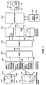
- FIGURE 2 is a block diagram of a VOP coder and decoder in accordance with the present invention.
- FIGURE 3 is an illustration of pixel upsampling in accordance with the present invention.
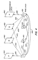
- FIGURE 4 is an illustration of an example of the prediction process between VOPs in a base layer and enhancement layer.
- FIGURE 5 is an illustration of spatial and temporal scaling of a VOP in accordance with the present invention.
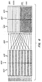
- FIGURE 6 illustrates the reordering of pixel lines from frame to field mode in accordance with the present invention.
- FIGURE 7 is an illustration of a picture-in-picture (PIP) or preview channel access application with spatial and temporal scaling in accordance with the present invention.
- PIP picture-in-picture
- FIGURE 8 is an illustration of a stereoscopic video application in accordance with the present invention.
- a method and apparatus are presented for providing temporal and spatial scaling of video images including video object planes (VOPs) in a digital video sequence.
- VOPs video object planes
- FIGURE 1 is an illustration of a video object coding and decoding process in accordance with the present invention.
- Frame 105 includes three pictorial elements, including a square foreground element 107, an oblong foreground element 108, and a landscape backdrop element 109.
- the elements are designated VOPs using a segmentation mask such that VOP 117 represents the square foreground element 107, VOP 118 represents the oblong foreground element 108, and VOP 119 represents the landscape backdrop element 109.
- a VOP can have an arbitrary shape, and a succession of VOPs is known as a video object.
- a full rectangular video frame may also be considered to be a VOP.
- VOP will be used herein to indicate both arbitrary and non-arbitrary image area shapes.
- a segmentation mask is obtained using known techniques, and has a format similar to that of ITU-R 601 luminance data. Each pixel is identified as belonging to a certain region in the video frame.
- the frame 105 and VOP data from frame 115 are supplied to separate encoding functions.
- VOPs 117, 118 and 119 undergo shape, motion and texture encoding at encoders 137, 138 and 139, respectively.
- shape coding binary and gray scale shape information is encoded.
- motion coding the shape information is coded using motion estimation within a frame.
- texture coding a spatial transformation such as the DCT is performed to obtain transform coefficients which can be variable-length coded for compression.
- the coded VOP data is then combined at a multiplexer (MUX) 140 for transmission over a channel 145.
- MUX multiplexer
- the data may be stored on a recording medium.
- the received coded VOP data is separated by a demultiplexer (DEMUX) 150 so that the separate VOPs 117-119 are decoded and recovered.
- Frames 155, 165 and 175 show that VOPs 117, 118 and 119, respectively, have been decoded and recovered and can therefore be individually manipulated using a compositor 160 which interfaces with a video library 170, for example.
- the compositor may be a device such as a personal computer which is located at a user's home to allow the user to edit the received data to provide a customized image.
- the user's personal video library 170 may include a previously stored VOP 178 (e.g., a circle) which is different than the received VOPs.
- the user may compose a frame 185 where the circular VOP 178 replaces the square VOP 117.
- the frame 185 thus includes the received VOPs 118 and 119 and the locally stored VOP 178.
- the background VOP 109 may be replaced by a background of the user's choosing.
- the announcer when viewing a television news broadcast, the announcer may be coded as a VOP which is separate from the background, such as a news studio.
- the user may select a background from the library 170 or from another television program, such as a channel with stock price or weather information. The user can therefore act as a video editor.
- the video library 170 may also store VOPs which are received via the channel 145, and may access VOPs and other image elements via a network such as the Internet.
- the frame 105 may include regions which are not VOPs and therefore cannot be individually manipulated. Furthermore, the frame 105 need not have any VOPs. Generally, a video session comprises a single VOP, or a sequence of VOPs.
- the video object coding and decoding process of FIGURE 1 enables many entertainment, business and educational applications, including personal computer games, virtual environments, graphical user interfaces, videoconferencing, Internet applications and the like.
- the capability for spatial and temporal scaling of the VOPs in accordance with the present invention provides even greater capabilities.
- FIGURE 2 is a block diagram of a video object coder and decoder in accordance with the present invention.
- the encoder 201 which corresponds to elements 137-139 shown schematically in FIGURE 1, includes a scalability preprocessor 205 which receives an input video data sequence "in".
- "in” is spatially downsampled to obtain the signal "in_0", which is, in turn, provided to a base layer encoder 220 via a path 217.
- “in_0” is encoded at the base layer encoder 220, and the encoded data is provided to a multiplexer (MUX) 230.
- MUX multiplexer
- a MPEG-4 System and Description Language (MSDL) MUX may be used.
- the reconstructed image data is provided from the base layer encoder 220 to a midprocessor 215 via a path 218 which may perform pixel upsampling, as discussed below in greater detail in connection with FIGURE 3.
- the upsampled image data which is in frame mode, is then provided to an enhancement layer encoder 210 via a path 212, where it is differentially encoded using the input image data "in_1" provided from the preprocessor 205 to the encoder 210 via a path 207.
- the upsampled pixel data e.g., luminance data
- coding efficiency when the input video sequence is in field mode, coding efficiency can be improved by grouping the pixel lines of the upsampled enhancement layer image which correspond to the original even (top) and odd (bottom) field of the input video sequence. This can decrease the magnitude of the residue in some cases since pixel data within a field will often have a greater correlation with other pixel data in the same field than with the data in the opposite field. Thus, by reducing the magnitude of the residue, fewer bits are required to code the image data. Refer to FIGURE 6 and the associated discussion, below, for further details.
- the encoded residue of the upsampled image in the enhancement layer is provided to the MUX 230 for transmission with the base layer data over a communication channel 245.
- the data may alternatively be stored locally.
- the MUX 230, channel 245, and DEMUX 250 correspond, respectively, to elements 140, 145 and 150 in FIGURE 1.
- the image data which is provided to the midprocessor 215 from the base layer encoder 220 may be the entire video image, such as a full-frame VOP, or a VOP which is a subset of the entire image. Moreover, a plurality of VOPs may be provided to the midprocessor 215. MPEG-4 currently supports up to 256 VOPs.
- the encoded data is received at a demultiplexer (DEMUX) 250, such as an MPEG-4 MSDL DEMUX.
- the enhancement layer data which has a higher spatial resolution than the base layer data in the present example, is provided to an enhancement layer decoder 260.
- the base layer data is provided to a base layer decoder 270, where the signal "out_0" is recovered and provided to a midprocessor 265 via a path 267, and to a scalability postprocessor 280 via a path 277.
- the midprocessor operates in a similar manner to the midprocessor 215 on the encoder side by upsampling the base layer data to recover a full-resolution image.
- This image is provided to the enhancement layer decoder 260 via a path 262 for use in recovering the enhancement layer data signal "out_1", which is then provided to the scalability postprocessor 280 via path 272.
- the scalability postprocessor 280 performs operations such as spatial upsampling of the decoded base layer data for display as signal "outp_0", while the enhancement layer data is output for display as signal "outp_1".
- the preprocessor 205 performs temporal demultiplexing (e.g., pulldown processing or frame dropping) to reduce the frame rate, e.g., for the base layer. For example, to decrease the frame rate from 30 frames/sec. to 15 frames/sec., every other frame is dropped.
- temporal demultiplexing e.g., pulldown processing or frame dropping
- Table 1 below shows twenty-four possible configurations of the midprocessors 215 and 265, scalability preprocessor 205 and scalability postprocessor 280.
- the first column indicates the configuration number
- the second column indicates the layer
- the third column indicates the temporal resolution of the layer (e.g., either high or low).
- the temporal resolution of the base and enhancement layers is either both high or both low.
- the fourth column indicates the spatial resolution.
- the fifth, sixth and seventh columns indicate the corresponding action of the scalability preprocessor 205, midprocessor 215 and 265, and scalability postprocessor 280.
- N/C denotes no change in temporal or spatial resolution, i.e., normal processing is performed.
- N/A means “not applicable.”
- the midprocessor 215, 265 actions do not affect the enhancement layer.
- Spatially scaled coding is illustrated using configuration 1 as an example.
- the preprocessor 205 produces two substreams of VOPs with different spatial resolutions.
- the base layer has a low spatial resolution
- the enhancement layer has a high spatial resolution which corresponds to the resolution of the input sequence. Therefore, the base-layer sequence "in_0" is generated by a downsampling process of the input video sequence "in” at the scalability preprocessor 205.
- the enhancement layer sequence is generated by upsample filtering of the downsampled base layer sequence at the midprocessors 215, 265 to achieve the same high spatial resolution of "in”.
- the postprocessor 280 performs normal processing, i.e., it does not change the temporal or spatial resolution of "out_1" or "out_0".
- a base layer CIF resolution sequence (360x288 pixels) can be generated from a 2:1 downsample filtering of an ITU-R 601 resolution input sequence (720x576 pixels). Downsampling by any integral or non-integral ratio may be used.
- Temporally and spatially scaled coding is illustrated using configuration 2 as an example.
- the input video sequence "in” which has a high spatial and temporal resolution, is converted to a base layer sequence having a low spatial and temporal resolution, and an enhancement layer sequence having a high spatial and temporal resolution.
- This is accomplished as indicated by Table 1 by performing downsample filtering and pulldown processing at the preprocessor 205 to provide the signal "in_0", with upsample filtering at the midprocessors 215, 265 and normal processing at the postprocessor 280.
- FIGURE 3 is an illustration of pixel upsampling in accordance with the present invention.
- Upsampling filtering may be performed by the midprocessors 215, 265 with configuration 1 of Table 1.
- a VOP having a CIF resolution 360x288 pixels
- ITU-R 601 resolution 720x576 pixels
- Pixels 310, 320, 330 and 340 of the CIF image are sampled to produce pixels 355, 360, 365, 370, 375, 380, 385 and 390 of the ITU-R 601 image.
- an ITU-R 601 pixel 360 is produced by sampling CIF pixels 310 and 320 as shown by arrows 312 and 322, respectively.
- an ITU-R 601 pixel 365 is also produced by sampling CIF pixels 310 and 320, as shown by arrows 314 and 324, respectively.
- FIGURE 4 is an illustration of an example of the prediction process between VOPs in the base layer and enhancement layer.
- a VOP of the enhancement layer is encoded as either a P-VOP or B-VOP.
- VOPs in the enhancement layer have a greater spatial resolution than base layer VOPs and are therefore drawn with a larger area.
- the temporal resolution e.g., frame rate
- the VOPs are shown in presentation order from left to right.
- the base layer includes an I-VOP 405, B-VOPs 415 and 420, and a P-VOP 430.
- the enhancement layer includes P-VOPs 450 and 490, and B-VOPs 460 and 480.
- B-VOP 415 is predicted from other base layer VOPs as shown by arrows 410 and 440, while B-VOP 420 is also predicted from the other base layer VOPs as shown by arrows 425 and 435.
- P-VOP 430 is predicted from I-VOP 405 as shown by arrow 445.
- P-VOP 450 is derived by upsampling a base layer VOP indicated by arrow 455, while P-VOP 490 is derived from upsampling a base layer VOP indicated by arrow 495.
- B-VOP 460 is predicted from base layer VOPs as shown by arrows 465 and 475, and B-VOP 480 is predicted from base layer VOPs as shown by arrows 470 and 485.
- the enhancement layer VOP which is temporally coincident (e.g., in display or presentation order) with an I-VOP in the base layer is encoded as a P-VOP.
- VOP 450 is temporally coincident with I-VOP 405, and is therefore coded as a P-VOP.
- the enhancement layer VOP which is temporally coincident with a P-VOP in the base layer is encoded as either a P- or B-VOP.
- VOP 490 is temporally coincident with P-VOP 430 and is coded as a P-VOP.
- the enhancement layer VOP which is temporally coincident with a B-VOP in the base layer is encoded as a B-VOP. For example, see B-VOPs 460 and 480.
- I-VOP 405 and P-VOP 430 are known as anchor VOPs since they are used as prediction references for the enhancement layer VOPs. I-VOP 405 and P-VOP 430 are therefore coded before the encoding of the corresponding predicted VOPs in the enhancement layer.
- the prediction reference of a P-VOP in the enhancement layer is specified by the forward (prediction) temporal reference indicator forward_temporal_ref in an MPEG-4 compatible syntax. Such an indicator is a non-negative integer which points to the temporally coincided I-VOP in the base layer.
- the prediction references of B-VOPs in the enhancement layer are specified by ref_select_code, forward_temporal_ref and backward_temporal_ref. See Table 2, below.
- VOP_prediction_type In coding both the base and enhancement layers, the prediction mode is indicated by a 2-bit word VOP_prediction_type given by Table 3, below.
- An "I” prediction type indicates an intra-coded VOP
- a "P” prediction type indicates a predicted VOP
- a "B” prediction type indicates a bi-directionally predicted VOP.
- the encoding process for the sequence "in_0" of the base layer is the same as a non-scaleable encoding process, e.g., according to the MPEG-2 Main profile or H.263 standard.
- FIGURE 6 illustrates the reordering, or permutation, of pixel lines from frame to field mode in accordance with the present invention.
- the resulting VOP when an input VOP is in field mode and is downsampled, the resulting VOP will be in frame mode. Accordingly, when the downsampled image is spatially upsampled, the resulting VOP will also be in frame mode.
- the upsampled VOP is differentially encoded by subtracting the input VOP from upsampled VOP, the resulting residue may not yield an optimal coding efficiency when a spatial transformation such as the DCT is subsequently performed on the residue.
- the magnitude of the residue values can be reduced by permuting (i.e., reordering) the lines of the upsampled image to group the even and odd lines since there may be a greater correlation between same-field pixels than opposite-field pixels.
- An image which may represent upsampled pixel (e.g., luminance) data in an enhancement layer is shown generally at 600.
- the image 600 is a 16x16 macroblock which is derived by 2:1 upsampling of an 8x8 block.
- the macroblock includes even numbered lines 602, 604, 606, 608, 610, 612, 614 and 616, and odd-numbered lines 603, 605, 607, 609, 611, 613, 615 and 617.
- the even and odd lines form top and bottom fields, respectively.
- the macroblock 600 includes four 8x8 luminance blocks, including a first block defined by the intersection of region 620 and lines 602-609, a second block defined by the intersection of region 625 and lines 602-609, a third block defined by the intersection of region 620 and lines 610-617, and a fourth block defined by the intersection of region 625 and lines 610-617.
- the macroblock shown generally at 650 is formed.
- Arrows, shown generally at 645, indicate the reordering of the lines 602-617.
- the even line 602 which is the first line of macroblock 600, is also the first line of macroblock 650.
- the even line 604 is made the second line in macroblock 650.
- the even lines 606, 608, 610, 612, 614 and 616 are made the third through eighth lines, respectively, of macroblock 650.
- a 16x8 luminance region 680 with even-numbered lines is formed.
- a first 8x8 block is defined by the intersection of region 680 and 670, while a second 8x8 block is defined by the intersection of regions 680 and 675.
- the region 685 comprises a first 8x8 block defined by the intersection of region 685 and 670, while a second 8x8 block is defined by the intersection of regions 685 and 675.
- Region 685 thus includes odd lines 603, 605, 607, 609, 611, 613, 615 and 617.
- the DCT which is performed on the residue is referred to herein as either "field DCT” or "frame DCT” or the like according to whether or not the macroblock 600 is reordered as shown at macroblock 650.
- field DCT the luminance lines (or luminance error) in the spatial domain of the macroblock are permuted from a frame DCT orientation to the top (even) and bottom (odd) field DCT configuration.
- the resulting macroblocks are transformed, quantized and variable length encoded normally.
- IDCT inverse DCT
- p i,j is the spatial luminance difference (e.g., residue) data just before the DCT is performed on each of the 8x8 luminance blocks.
- the error terms refer to opposite-field pixel differences (e.g., even to odd, and odd to even).
- the left hand side is a sum of differences of luminance values of opposite-field lines.
- the error terms are referring to same-field pixel differences (e.g., even to even, and odd to odd).
- the right hand side is a sum of differences of luminance data of same-field lines and a bias term.
- a second order equation may be used to determine whether frame or field DCT should be used by modifying the above equation to take the square of each error term rather than the absolute value. In this case, the "bias" term is not required.
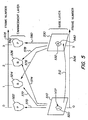
- FIGURE 5 is an illustration of spatial and temporal scaling of a VOP in accordance with the present invention.
- the frame rate and spatial resolution of a selected VOP can be enhanced such that it has a higher quality than the remaining area, e.g., the frame rate and/or spatial resolution of the selected object can be higher than that of the remaining area.
- a VOP of a news announcer may be provided with a higher resolution than a studio backdrop.
- Axes 505 and 506 indicate a frame number.
- frame 510 which includes VOP 520 is provided in the frame 0 position
- frame 530 with VOP 532 (corresponding to VOP 520) is provided in the frame 3 position.
- frame 530 is predicted from frame 510, as shown by arrow 512.
- the enhancement layer includes VOPs 522, 524, 526 and 542. These VOPs have an increased spatial resolution relative to VOPs 520 and 532 and therefore are drawn with a larger area.
- P-VOP 522 is derived from upsampling VOP 520, as shown by arrow 570.
- B-VOPs 524 and 526 are predicted from base layer VOPs 520 and 532, as shown by arrows 572 and 576, and 574 and 578, respectively.
- the input video sequence which is used to create the base and enhancement layer sequences has full resolution (e.g. 720x480 for ITU-R 601 corresponding to National Television Standards Committee (NTSC) or 720x576 for ITU-R corresponding to Phase Alternation Line (PAL)) and full frame rate (30 frames /60 fields for ITU-R corresponding to NTSC or 25 frames/50 fields for ITU-R 601 corresponding to PAL).
- Scaleable coding is performed such that the resolution and frame rate of objects are preserved by using the enhancement layer coding.
- the video object in the base layer, comprising VOPs 520 and 532 has a lower resolution (e.g. quarter size of the full resolution VOP) and a lower frame rate (e.g. one third of the original frame rate).
- VOP 520 is enhanced.
- the remainder of the frame 510 is not enhanced. While only one VOP is shown, virtually any number of VOPs may be provided. Moreover, when two or more VOPs are provided, all or only selected ones may be enhanced.
- the base layer sequence is generated by downsampling and frame-dropping of the original sequence.
- the base layer VOPs are then coded as I-VOPs or P-VOPs by using progressive coding tools.
- interlaced coding tools such as field/frame motion estimation and compensation, and field/frame DCT are not used since downsampling of the input interlaced video sequence produces a progressive video sequence.
- the enhancement layer VOPs are coded using temporal and spatial scaleable tools.
- VOP 522 and VOP 542 are coded as P-VOPs using spatial scalability.
- VOP 524 and VOP 526 are coded as B-VOPs from the upsampled VOPs of the base layer reference VOPs, i.e., VOP 520 and VOP 532, respectively, using temporal scaleable tools.
- a technique for reducing encoding complexity for motion estimation of B-VOPs by reducing the motion vector search range.
- the technique is applicable to both frame mode and field mode input video sequences.
- the searching center of the reference VOP is determined by scaling the motion vector of the corresponding base layer VOP rather than by performing an independent exhaustive search in the reference VOP.
- Such as exhaustive search would typically cover a range, for example, of +/- 64 pixels horizontally, and +/- 48 pixels vertically, and would therefore be less efficient than the disclosed technique.
- MV f is the forward motion vector
- MV b is the backward motion vector
- MV p is the motion vector for the P-VOP (e.g.
- TR B is the temporal distance between the past reference VOP (e.g., VOP 520) and the current B-VOP in the enhancement layer
- TR p is the temporal distance between the past reference VOP and the future reference P-VOP (e.g., VOP 532) in the base layer.
- m/n is the ratio of the spatial resolution of the base layer VOPs to the spatial resolution of the enhancement layer VOPs. That is, either the base layer VOPs or the B-VOP in the enhancement layer may be downsampled relative to the input video sequence by a ratio m/n.
- m/n is the downsampling ratio of the base layer VOP which is subsequently upsampled to provide the enhancement layer VOP.
- m/n may be less than, equal to, or greater than one.
- all of the motion vectors are two-dimensional.
- the motion vector searching range is a 16x16 rectangular region, for example, whose center is determined by MV f and MV b .
- the motion vectors are communicated with the enhancement and base layer video data in a transport data stream, and are recovered by a decoder for use in decoding the video data.
- interlaced coding tools are used to achieve better performance. These tools include Field/Frame DCT for intra-macroblocks and inter-difference macroblocks, and field prediction, i.e., top field to bottom field, top field to top field, bottom field to top field and bottom field to bottom field.
- FIGURE 7 is an illustration of a picture-in-picture (PIP) or preview channel access application with spatial and temporal scaling in accordance with the present invention.
- PIP picture-in-picture
- a secondary program is provided as a subset of a main program which is viewed on the television. Since the secondary program has a smaller area, the viewer is less discerning of a reduced resolution image, so the temporal and/or spatial resolution of the PIP image can be reduced to conserve bandwidth.
- a preview access channel program may provide a viewer with a free low-resolution sample of a program which may be purchased for a fee.
- This application provides a few minutes of free access of an authorized channel (e.g., Pay-Per-View) for a preview.
- Video coded in the preview access channel will have lower resolution and lower frame rate. The decoder will control the access time for such a preview channel.
- Configuration 2 of the temporal-spatial scaleable coding in Table 1, above may be used to provide an output from decoding the base layer that has a lower spatial resolution than the output from decoding both the base layer and the enhancement layer.
- the video sequence in the base layer can be coded with a low frame rate, while the enhancement layer is coded with a higher frame rate.
- a video sequence in the base layer can have a CIF resolution and a frame rate of 15 frames/second, while the corresponding video sequence in the enhancement layer has an ITU-R 601 resolution and a frame rate of 30 frames/second.
- the enhancement layer may conform to the NTSC video standard, while PIP or preview access functionality is provided by the base layer, which may conform to a CIF standard. Accordingly, PIP functionality can be provided by scaleable coding with a similar coding complexity and efficiency as the MPEG-2 Main Profile at Main Level standard.
- the base layer includes low spatial resolution VOPs 705 and 730. Moreover, the temporal resolution of the base layer is 1/3 that of the enhancement layer.
- the enhancement layer includes high spatial resolution VOPs 750, 760, 780 and 790.
- P-VOP 750 is derived by upsampling I-VOP 705, as shown by arrow 755.
- B-VOP 760 is predicted from the base later VOPs as shown by arrows 765 and 775.
- B-VOP 780 is predicted from the base later VOPs as shown by arrows 770 and 785.
- P-VOP 790 is derived by upsampling P-VOP 730, as shown by arrow 795.
- FIGURE 8 is an illustration of a stereoscopic video application in accordance with the present invention.
- Stereoscopic video functionality is provided in the MPEG-2 Multi-view Profile (MVP) system, described in document ISO/IEC JTC1/SC29/WG11 N1196.
- MVP MPEG-2 Multi-view Profile
- the base layer is assigned to the left view and the enhancement layer is assigned to the right view.
- the enhancement layer pictures can be coded with a lower resolution than the base layer.
- configuration 4 in Table 1, above can be used where the base layer has a ITU-R 601 spatial resolution, while the enhancement layer has a CIF spatial resolution.
- the reference pictures of the base layer for the prediction of the enhancement layer pictures are downsampled. Accordingly, the decoder for the enhancement layer pictures includes an upsampling process. Additionally, adaptive frame/field DCT coding is used in the base layer but not the enhancement layer.
- the base layer includes VOPs 805, 815, 820 and 830, while the enhancement layer includes VOPs 850, 860, 880 and 890.
- B-VOPs 815 and 820 are predicted using other base layer VOPs as shown by arrows 810, 840, and 835, 825, respectively.
- P-VOP 830 is predicted from I-VOP 805 as shown by arrow 845.
- P-VOP 850 is derived by downsampling I-VOP 805, as shown by arrow 855.
- B-VOP 860 is predicted from the base later VOPs as shown by arrows 865 and 875.
- B-VOP 880 is predicted from the base later VOPs as shown by arrows 870 and 885.
- P-VOP 890 is derived by downsampling P-VOP 830, as shown by arrow 895.
- the base and enhancement layers may have the same spatial resolution and frame rate, configuration 7 in Table 1, above, may be used.
- the coding process of the base layer may be the same as a non-scaleable encoding process, e.g., such as described in the MPEG-4 VM non-scaleable coding or MPEG-2 Main Profile at Main Level standard, while adaptive frame/field DCT coding is used in the enhancement layer.
- ATM asynchronous transfer mode
- VBR variable bit rate
- CBR constant bit rate
- video sources in ATM networks can be statistically multiplexed, requiring a lower transmission bit rate than if they are transmitted through CBR channels since the long term average data rate of a video signal is less than the short term average due to elastic buffering in CBR systems.
- the temporal-spatial scaleable coding techniques of the present invention can be used.
- video data from the base layer can be transmitted with a high priority and accommodated in a guaranteed bit rate of an ATM network.
- Video data packets from the enhancement layer may be lost if congestion arises since a channel is not guaranteed. If the enhancement layer packets are received, picture quality is improved.
- a coding scheme using configuration 1 of Table 1, above, may be used to achieve this result. The scheme may be achieved as shown in FIGURE 4, discussed previously in connection with prediction modes, where the base layer is the high-priority layer.
- higher priority, lower bit rate data is communicated in the base layer
- lower priority higher bit rate data is communicated in the enhancement layer.
- scaleable coding can also be used in video coding and transmission over the Internet, intranets and other communication networks.
- the present invention provides a method and apparatus for providing temporal and spatial scaling of video images including video object planes (VOPs) in a digital video sequence.
- VOPs video object planes
- coding efficiency is improved by adaptively compressing a scaled field mode input video sequence. Upsampled VOPs in the enhancement layer are reordered to provide a greater correlation with the original video sequence based on a linear criteria. The resulting residue is coded using a spatial transformation such as the DCT.
- a motion compensation scheme is presented for coding enhancement layer VOPs by scaling motion vectors which have already been determined for the base layer VOPs. A reduced search area is defined whose center is defined by the scaled motion vectors. The technique is suitable for use with a scaled frame mode or field mode input video sequence.
Abstract
Description


| ref_select_code | forward temporal reference VOP | backward temporal reference VOP |
| 00 | base layer | base layer |
| 01 | base layer | enhancement layer |
| 10 | enhancement layer | base layer |
| 11 | enhancement layer | enhancement layer |
| VOP_prediction_type | Code |
| I | 00 |
| P | 01 |
| B | 10 |
Claims (45)
- A method for scaling an input video sequence comprising video object planes (VOPs) for communication in a corresponding base layer and enhancement layer, said VOPs in said input video sequence having an associated spatial resolution and temporal resolution, comprising the steps of:downsampling pixel data of a first particular one of said VOPs of said input video sequence to provide a first base layer VOP having a reduced spatial resolution;upsampling pixel data of at least a portion of said first base layer VOP to provide a first upsampled VOP in said enhancement layer; anddifferentially encoding said first upsampled VOP using said first particular one of said VOPs of said input video sequence for communication in said enhancement layer at a temporal position corresponding to said first base layer VOP.
- The method of claim 1, wherein said VOPs in said input video sequence are field mode VOPs, and said differentially encoding step comprises the further steps of:reordering lines of said pixel data of said first upsampled VOP in a field mode if said lines of pixel data meet a reordering criteria; thendetermining a residue according to a difference between pixel data of said first upsampled VOP and pixel data of said first particular one of said VOPs of said input video sequence;and spatially transforming said residue to provide transform coefficients.
- The method of claim 2, wherein:said lines of pixel data of said first upsampled VOP meet said reordering criteria when a sum of differences of luminance values of opposite-field lines is greater than a sum of differences of luminance data of same-field lines and a bias term.
- The method of any of the preceding claims, comprising the further steps of:downsampling pixel data of a second particular one of said VOPs of said input video sequence to provide a second base layer VOP having a reduced spatial resolution;upsampling pixel data of at least a portion of said second base layer VOP to provide a second upsampled VOP in said enhancement layer which corresponds to said first upsampled VOP;using at least one of said first and second base layer VOPs to predict an intermediate VOP corresponding to said first and second upsampled VOPs; andencoding said intermediate VOP for communication in said enhancement layer at a temporal position which is intermediate to that of said first and second upsampled VOPs.
- The method of claim 4, wherein:said enhancement layer has a higher temporal resolution than said base layer; andsaid base and enhancement layer are adapted to provide at least one of:(a) a picture-in-picture (PIP) capability wherein a PIP image is carried in said base layer, and(b) a preview access channel capability wherein a preview access image is carried in said base layer.
- The method of any of the preceding claims, wherein:said base layer is adapted to carry higher priority, lower bit rate data, and said enhancement layer is adapted to carry lower priority, higher bit rate data.
- A method for scaling an input video sequence comprising video object planes (VOPs) for communication in a corresponding base layer and enhancement layer, said VOPs in said input video sequence having an associated spatial resolution and temporal resolution, comprising the steps of:providing a first particular one of said VOPs of said input video sequence for communication in said base layer as a first base layer VOP.downsampling pixel data of at least a portion of said first base layer VOP for communication in said enhancement layer as a first downsampled VOP at a temporal position corresponding to said first base layer VOP;downsampling corresponding pixel data of said first particular one of said VOPs to provide a comparison VOP; anddifferentially encoding said first downsampled VOP using said comparison VOP.
- The method of claim 7, comprising the further steps of:differentially encoding said first base layer VOP using said first particular one of said VOPs by:determining a residue according to a difference between pixel data of said first base layer VOP and pixel data of said first particular one of said VOPs;and spatially transforming said residue to provide transform coefficients.
- The method of claim 8, wherein said VOPs in said input video sequence are field mode VOPs, and said first base layer VOP is differentially encoded by the steps of:reordering lines of said pixel data of said first base layer VOP in a field mode prior to said determining step if said lines of pixel data meet a reordering criteria.
- The method of claim 9, wherein:said lines of pixel data of said first base layer VOP meet said reordering criteria when a sum of differences of luminance values of opposite-field lines is greater than a sum of differences of luminance data of same-field lines and a bias term.
- The method of any of claims 7 to 10, comprising the further steps of:providing a second particular one of said VOPs of said input video sequence for communication in said base layer as a second base layer VOP;downsampling pixel data of at least a portion of said second base layer VOP for communication in said enhancement layer as a second downsampled VOP at a temporal position corresponding to said second base layer VOP;downsampling corresponding pixel data of said second particular one of said VOPs to provide a comparison VOP;differentially encoding said second downsampled VOP using said Comparison VOP;using at least one of said first and second base layer VOPs to predict an intermediate VOP corresponding to said first and second downsampled VOPs; andencoding said intermediate VOP for communication in said enhancement layer at a temporal position which is intermediate to that of said first and second upsampled VOPs.
- The method of any of claims 7 to 11, wherein:the base and enhancement layers are adapted to provide a stereoscopic video capability in which image data in the enhancement layer has a lower spatial resolution than image data in the base layer.
- A method for coding a bi-directionally predicted video object plane (B-VOP), comprising the steps of:scaling an input video sequence comprising video object planes (VOPs) for communication in a corresponding base layer and enhancement layer;providing first and second base layer VOPs in said base layer which correspond to said input video sequence VOPs;said second base layer VOP being predicted from said first base layer VOP according to a motion vector MVp;providing said B-VOP in said enhancement layer at a temporal position which is intermediate to that of said first and second base layer VOPs; andencoding said B-VOP using at least one of:(a) a forward motion vector MVf and(b) a backward motion vector MVB, obtained by scaling said motion vector MVp.
- The method of claim 13, wherein:a temporal distance TRp separates said first and second base layer VOPs;a temporal distance TRB separates said first base layer VOP and said B-VOP;m/n is a ratio of the spatial resolution of the first and second base layer VOPs to the spatial resolution of the B-VOP; andat least one of:(a) said forward motion vector MVf is determined according to the relationship(b) said backward motion vector MVb is determined according to the relationship
- The method of claim 13 or 14, comprising the further step of:encoding said B-VOP using at least one of:(a) a search region of said first base layer VOP whose center is determined according to said forward motion vector MVf; and(b) a search region of said second base layer VOP whose center is determined according to said backward motion vector MVB.
- A method for recovering an input video sequence comprising video object planes (VOPs) which was scaled and communicated in a corresponding base layer and enhancement layer, said VOPs in said input video sequence having an associated spatial resolution and temporal resolution, wherein:pixel data of a first particular one of said VOPs of said input video sequence is downsampled and carried as a first base layer VOP having a reduced spatial resolution;pixel data of at least a portion of said first base layer VOP is upsampled and carried as a first upsampled VOP in said enhancement layer at a temporal position corresponding to said first base layer VOP; andsaid first upsampled VOP is differentially encoded using said first particular one of said VOPs of said input video sequence;said method comprising the steps of:upsampling said pixel data of said first base layer VOP to restore said associated spatial resolution; andprocessing said first upsampled VOP and said first base layer VOP with said restored associated spatial resolution to provide an output video signal with said associated spatial resolution.
- The method of claim 16, wherein:said VOPs in said input video sequence are field mode VOPs; andsaid first upsampled VOP is differentially encoded by reordering lines of said pixel data of said first upsampled VOP in a field mode if said lines of pixel data meet a reordering criteria, then determining a residue according to a difference between pixel data of said first upsampled VOP and pixel data of said first particular one of said VOPs of said input video sequence, and spatially transforming said residue to provide transform coefficients.
- The method of claim 17, wherein:said lines of pixel data of said first upsampled VOP meet said reordering criteria when a sum of differences of luminance values of opposite-field lines is greater than a sum of differences of luminance data of same-field lines and a bias term.
- The method of any of claims 16 to 18, wherein:a second particular one of said VOPs of said input video sequence is downsampled to provide a second base layer VOP having a reduced spatial resolution;pixel data of at least a portion of said second base layer VOP is upsampled to provide a second upsampled VOP in said enhancement layer which corresponds to said first upsampled VOP;at least one of said first and second base layer VOPs is used to predict an intermediate VOP corresponding to said first and second upsampled VOPs; andsaid intermediate VOP is encoded for communication in said enhancement layer at a temporal position which is intermediate to that of said first and second upsampled VOPs.
- The method of claim 19, wherein:said enhancement layer has a higher temporal resolution than said base layer; andsaid base and enhancement layer are adapted to provide at least one of:(a) a picture-in-picture (PIP) capability wherein a PIP image is carried in said base layer, and(b) a preview access channel capability wherein a preview access image is carried in said base layer.
- The method of any of claims 16 to 20, wherein:said base layer is adapted to carry higher priority, lower bit rate data, and said enhancement layer is adapted to carry lower priority, higher bit rate data.
- A method for recovering an input video sequence comprising video object planes (VOPs) which was scaled and communicated in a corresponding base layer and enhancement layer, said VOPs in said input video sequence having an associated spatial resolution and temporal resolution, wherein:a first particular one of said VOPs of said input video sequence is provided in said base layer as a first base layer VOP;pixel data of at least a portion of said first base layer VOP is downsampled and carried in said enhancement layer as a first downsampled VOP at a temporal position corresponding to said first base layer VOP;corresponding pixel data of said first particular one of said VOPs is downsampled to provide a comparison VOP; andsaid first downsampled VOP is differentially encoded using said comparison VOP;said method comprising the steps of:upsampling said pixel data of said first downsampled VOP to restore said associated spatial resolution; andprocessing said first enhancement layer VOP with said restored associated spatial resolution and said first base layer VOP to provide an output video signal with said associated spatial resolution.
- The method of claim 22, wherein:said first base layer VOP is differentially encoding using said first particular one of said VOPs by determining a residue according to a difference between pixel data of said first base layer VOP and pixel data of said first particular one of said VOPs, and spatially transforming said residue to provide transform coefficients.
- The method of claim 23, wherein:said VOPs in said input video sequence are field mode VOPs, and said first base layer VOP is differentially encoded by reordering lines of said pixel data of said first base layer VOP in a field mode prior to determining said residue if said lines of pixel data meet a reordering criteria
- The method of claim 24, wherein:said lines of pixel data of said first base layer VOP meet said reordering criteria when a sum of differences of luminance values of opposite-field lines is greater than a sum of differences of luminance data of same-field lines and a bias term.
- The method of any of claims 22 to 25, wherein:a second particular one of said VOPs of said input video sequence is provided in said base layer as a second base layer VOP;pixel data of at least a portion of said second base layer VOP is downsampled and carried in said enhancement layer as a second downsampled VOP at a temporal position corresponding to said second base layer VOP;corresponding pixel data of said second particular one of said VOPs is downsampled to provide a comparison VOP;said second downsampled VOP is differentially encoded using said comparison VOP;at least one of said first and second base layer VOPs is used to predict an intermediate VOP corresponding to said first and second upsampled VOPs; andsaid intermediate VOP is encoded for communication in said enhancement layer at a temporal position which is intermediate to that of said first and second upsampled VOPs.
- The method of any of claims 22 to 26, wherein:said base and enhancement layer are adapted to provide a stereoscopic video capability in which image data in said enhancement layer has a lower spatial resolution than image data in said base layer.
- A method for recovering an input video sequence comprising video object planes (VOPs) which was scaled and communicated in a corresponding base layer and enhancement layer in a data stream, said VOPs in said input video sequence having an associated spatial resolution and temporal resolution, wherein:first and second base layer VOPs are provided in said base layer which correspond to said input video sequence VOPs;said second base layer VOP is predicted from said first base layer VOP according to a motion vector MVp;a bi-directionally predicted video object plane (B-VOP) is provided in said enhancement layer at a temporal position which is intermediate to that of said first and second base layer VOPs; andsaid B-VOP is encoded using a forward motion vector MVf and a backward motion vector MVB which are obtained by scaling said motion vector MVp;said method comprising the steps of:recovering said forward motion vector MVf and said backward motion vector MVB from said data stream; anddecoding said B-VOP using said forward motion vector MVf and said backward motion vector MVB.
- The method of claim 28, wherein:a temporal distance TRp separates said first and second base layer VOPs;a temporal distance TRB separates said first base layer VOP and said B-VOP;m/n is a ratio of the spatial resolution of the first and second base layer VOPs to the spatial resolution of the B-VOP; andat least one of:(a) said forward motion vector MVf is determined according to the relationship(b) said backward motion vector MVb is determined according to the relationship
- The method of claim 28 or 29, wherein:said B-VOP is encoded using at least one of:(a) a search region of said first base layer VOP whose center is determined according to said forward motion vector MVf; and(b) a search region of said second base layer VOP whose center is determined according to said backward motion vector MVB.
- A decoder apparatus for recovering an input video sequence comprising video object planes (VOPs) which was scaled and communicated in a corresponding base layer and enhancement layer, said VOPs in said input video sequence having an associated spatial resolution and temporal resolution, wherein:pixel data of a first particular one of said VOPs of said input video sequence is downsampled and carried as a first base layer VOP having a reduced spatial resolution;pixel data of at least a portion of said first base layer VOP is upsampled and carried as a first upsampled VOP in said enhancement layer at a temporal position corresponding to said first base layer VOP; andsaid first upsampled VOP is differentially encoded using said first particular one of said VOPs of said input video sequence;said apparatus comprising:means for upsampling said pixel data of said first base layer VOP to restore said associated spatial resolution; andmeans for processing said first upsampled VOP and said first base layer VOP with said restored associated spatial resolution to provide an output video signal with said associated spatial resolution.
- The apparatus of claim 31, wherein:said VOPs in said input video sequence are field mode VOPs; andsaid first upsampled VOP is differentially encoded by reordering lines of said pixel data of said first upsampled VOP in a field mode if said lines of pixel data meet a reordering criteria, then determining a residue according to a difference between pixel data of said first upsampled VOP and pixel data of said first particular one of said VOPs of said input video sequence, and spatially transforming said residue to provide transform coefficients.
- The apparatus of claim 31 or 32, wherein:said lines of pixel data of said first upsampled VOP meet said reordering criteria when a sum of differences of luminance values of opposite-field lines is greater than a sum of differences of luminance data of same-field lines and a bias term.
- The apparatus of any of claims 31 to 33, wherein:a second particular one of said VOPs of said input video sequence is downsampled to provide a second base layer VOP having a reduced spatial resolution;pixel data of at least a portion of said second base layer VOP is upsampled to provide a second upsampled VOP in said enhancement layer which corresponds to said first upsampled VOP;at least one of said first and second base layer VOPs is used to predict an intermediate VOP corresponding to said first and second upsampled VOPs; andsaid intermediate VOP is encoded for communication in said enhancement layer at a temporal position which is intermediate to that of said first and second upsampled VOPs.
- The apparatus of claim 34, wherein:said enhancement layer has a higher temporal resolution than said base layer; andsaid base and enhancement layers are adapted to provide at least one of:(a) a picture-in-picture (PIP) capability wherein a PIP image is carried in said base layer, and(b) a preview access channel capability wherein a preview access image is carried in said base layer.
- The apparatus of any of claims 31 to 35, wherein:said base layer is adapted to carry higher priority, lower bit rate data, and said enhancement layer is adapted to carry lower priority, higher bit rate data.
- A decoder apparatus for recovering an input video sequence comprising video object planes (VOPs) which was scaled and communicated in a corresponding base layer and enhancement layer, said VOPs in said input video sequence having an associated spatial resolution and temporal resolution, wherein:a first particular one of said VOPs of said input video sequence is provided in said base layer as a first base layer VOP;pixel data of at least a portion of said first base layer VOP is downsampled and carried in said enhancement layer as a first downsampled VOP at a temporal position corresponding to said first base layer VOP;corresponding pixel data of said first particular one of said VOPs is downsampled to provide a comparison VOP; andsaid first downsampled VOP is differentially encoded using said comparison VOP;said apparatus comprising:means for upsampling said pixel data of said first downsampled VOP to restore said associated spatial resolution; andmeans for processing said first enhancement layer VOP with said restored spatial resolution and said first base layer VOP to provide an output video signal with said associated spatial resolution.
- The apparatus of claim 37, wherein:said first downsampled VOP is differentially encoding by determining a residue according to a difference between pixel data of said first downsampled VOP and pixel data of said first particular one of said VOPs of said input video sequence, and spatially transforming said residue to provide transform coefficients.
- The apparatus of claim 38, wherein:said VOPs in said input video sequence are field mode VOPs, and said first base layer VOP is differentially encoded by reordering lines of said pixel data of said first base layer VOP in a field mode prior to determining said residue if said lines of pixel data meet a reordering criteria.
- The apparatus of claim 39, wherein:said lines of pixel data of said first base layer VOP meet said reordering criteria when a sum of differences of luminance values of opposite-field lines is greater than a sum of differences of luminance data of same-field lines and a bias term.
- The apparatus of any of claims 37 to 40, wherein:a second particular one of said VOPs of said input video sequence is provided for communication in said base layer as a second base layer VOP;pixel data of at least a portion of said second base layer VOP is downsampled to provide a second downsampled VOP in said enhancement layer which corresponds to said first upsampled VOP;at least one of said first and second base layer VOPs is used to predict an intermediate VOP corresponding to said first and second downsampled VOPs; andsaid intermediate VOP is encoded for communication in said enhancement layer at a temporal position which is intermediate to that of said first and second upsampled VOPs.
- The apparatus of any of claims 37 to 41, wherein:said base and enhancement layer are adapted to provide a stereoscopic video capability in which image data in said enhancement layer has a lower spatial resolution than image data in said base layer.
- A decoder apparatus for recovering an input video sequence comprising video object planes (VOPs) which was scaled and communicated in a corresponding base layer and enhancement layer in a data stream, said VOPs in said input video sequence having an associated spatial resolution and temporal resolution, wherein:first and second base layer VOPs which correspond to said input video sequence VOPs are provided in said base layer;said second base layer VOP is predicted from said first base layer VOP according to a motion vector MVp;a bi-directionally predicted video object plane (B-VOP) is provided in said enhancement layer at a temporal position which is intermediate to that of said first and second base layer VOPs; andsaid B-VOP is encoded using a forward motion vector MVf and a backward motion vector MVB which are obtained by scaling said motion vector MVp;said apparatus comprising:means for recovering said forward motion vector MVf and said backward motion vector MVB from said data stream; andmeans for decoding said B-VOP using said forward motion vector MVf and said backward motion vector MVB.
- The apparatus of claim 43, wherein:a temporal distance TRp separates said first and second base layer VOPs;a temporal distance TRB separates said first base layer VOP and said B-VOP;m/n is a ratio of the spatial resolution of the first and second base layer VOPs to the spatial resolution of the B-VOP; andat least one of:(a) said forward motion vector MVf is determined according to the relationship(b) said backward motion vector MVb is determined according to the relationship
- The apparatus of claim 43 or 44, wherein:said B-VOP is encoded using at least one of:(a) a search region of said first base layer VOP whose center is determined according to said forward motion vector MVf; and(b) a search region of said second base layer VOP whose center is determined according to said backward motion vector MVB.
Applications Claiming Priority (2)
| Application Number | Priority Date | Filing Date | Title |
|---|---|---|---|
| US08/869,493 US6057884A (en) | 1997-06-05 | 1997-06-05 | Temporal and spatial scaleable coding for video object planes |
| US869493 | 1997-06-05 |
Publications (3)
| Publication Number | Publication Date |
|---|---|
| EP0883300A2 true EP0883300A2 (en) | 1998-12-09 |
| EP0883300A3 EP0883300A3 (en) | 2000-12-20 |
| EP0883300B1 EP0883300B1 (en) | 2013-01-23 |
Family
ID=25353640
Family Applications (1)
| Application Number | Title | Priority Date | Filing Date |
|---|---|---|---|
| EP98109563A Expired - Lifetime EP0883300B1 (en) | 1997-06-05 | 1998-05-26 | Temporal and spatial scaleable coding for video object planes |
Country Status (10)
| Country | Link |
|---|---|
| US (1) | US6057884A (en) |
| EP (1) | EP0883300B1 (en) |
| JP (1) | JPH1118085A (en) |
| KR (1) | KR19990006678A (en) |
| CN (2) | CN1209020A (en) |
| AU (1) | AU733055B2 (en) |
| BR (1) | BR9801762A (en) |
| CA (1) | CA2238900C (en) |
| NO (1) | NO982508L (en) |
| TW (1) | TW406512B (en) |
Cited By (25)
| Publication number | Priority date | Publication date | Assignee | Title |
|---|---|---|---|---|
| WO2002017645A1 (en) * | 2000-08-24 | 2002-02-28 | France Telecom | Method for calculating an image interpolated between two images of a video sequence |
| US6501797B1 (en) | 1999-07-06 | 2002-12-31 | Koninklijke Phillips Electronics N.V. | System and method for improved fine granular scalable video using base layer coding information |
| WO2003036981A1 (en) * | 2001-10-26 | 2003-05-01 | Koninklijke Philips Electronics N.V. | Spatial scalable compression |
| EP1425707A2 (en) * | 2001-07-06 | 2004-06-09 | Vision III Imaging, Inc. | Image segmentation by means of temporal parallax difference induction |
| EP1566051A1 (en) * | 2002-11-25 | 2005-08-24 | Thomson Licensing | Two-layer encoding for hybrid high-definition dvd |
| EP1568221A1 (en) * | 2002-12-03 | 2005-08-31 | Thomson Licensing | Hybrid scalable encoder, method, and media for standard-definition and high-definition video formats on a single-disc |
| EP1574995A1 (en) * | 2004-03-12 | 2005-09-14 | Thomson Licensing S.A. | Method for encoding interlaced digital video data |
| WO2005091215A1 (en) * | 2004-03-18 | 2005-09-29 | Pixe Pty Ltd | System and method for transforming graphics data |
| WO2006042990A1 (en) * | 2004-10-20 | 2006-04-27 | Thomson Licensing | Method for hierarchically coding video images |
| WO2007020233A2 (en) * | 2005-08-18 | 2007-02-22 | Thomson Licensing | Method for encoding and decoding interleave high-resolution and progressive low-resolution images |
| EP1776832A1 (en) * | 2004-08-09 | 2007-04-25 | Electronics and Telecommunications Research Institute | 3-dimensional digital multimedia broadcasting system |
| WO2007047736A2 (en) * | 2005-10-19 | 2007-04-26 | Thomson Licensing | Multi-view video coding using scalable video coding |
| WO2007081908A1 (en) * | 2006-01-09 | 2007-07-19 | Thomson Licensing | Method and apparatus for providing reduced resolution update mode for multi-view video coding |
| EP2207352A1 (en) * | 2007-10-24 | 2010-07-14 | Huawei Device Co., Ltd. | A video encoding/decoding method and a video encoder/decoder |
| ITTO20110035A1 (en) * | 2011-01-19 | 2011-04-20 | Sisvel S P A | VIDEO FLOW CONSISTING OF COMBINED FRAME VIDEO, PROCEDURE AND DEVICES FOR ITS GENERATION, TRANSMISSION, RECEPTION AND REPRODUCTION |
| CN101478671B (en) * | 2008-01-02 | 2011-05-11 | 中兴通讯股份有限公司 | Video encoding apparatus applied on video monitoring and video encoding method thereof |
| US8111758B2 (en) | 2001-11-21 | 2012-02-07 | Electronics And Telecommunications Research Institute | 3D stereoscopic/multiview video processing system and its method |
| US8345762B2 (en) | 2005-02-18 | 2013-01-01 | Thomson Licensing | Method for deriving coding information for high resolution pictures from low resolution pictures and coding and decoding devices implementing said method |
| US8446956B2 (en) | 2006-01-05 | 2013-05-21 | Thomson Licensing | Inter-layer motion prediction method using resampling |
| US8520141B2 (en) | 2005-12-01 | 2013-08-27 | Thomson Licensing | Method of predicting motion and texture data |
| KR101357982B1 (en) * | 2006-01-09 | 2014-02-05 | 톰슨 라이센싱 | Method and apparatus for providing reduced resolution update mode for multi-view video coding |
| US20140168365A1 (en) * | 2011-05-17 | 2014-06-19 | S.I.Sv.El Societa' Italiana Per Lo Sviluppo Dell'elettronica S.P.A. | Method for generating, transmitting and receiving stereoscopic images, and related devices |
| US9167266B2 (en) | 2006-07-12 | 2015-10-20 | Thomson Licensing | Method for deriving motion for high resolution pictures from motion data of low resolution pictures and coding and decoding devices implementing said method |
| US9336609B2 (en) | 2012-12-07 | 2016-05-10 | Industrial Technology Research Institute | Image and message encoding system, encoding method, decoding system and decoding method |
| WO2023047094A1 (en) * | 2021-09-21 | 2023-03-30 | V-Nova International Ltd | Low complexity enhancement video coding with temporal scalability |
Families Citing this family (189)
| Publication number | Priority date | Publication date | Assignee | Title |
|---|---|---|---|---|
| US6404813B1 (en) * | 1997-03-27 | 2002-06-11 | At&T Corp. | Bidirectionally predicted pictures or video object planes for efficient and flexible video coding |
| CA2255923C (en) * | 1997-04-01 | 2005-06-07 | Sony Corporation | Picture coding device, picture coding method, picture decoding device, picture decoding method, and providing medium |
| US6741748B1 (en) * | 1997-06-19 | 2004-05-25 | Samsung Electronics Co. | Scan interleaving method based on context values of neighboring pixels, improved encoding/decoding method of binary shape data and encoding/decoding apparatus suitable for the same |
| US6993201B1 (en) | 1997-07-08 | 2006-01-31 | At&T Corp. | Generalized scalability for video coder based on video objects |
| US6233356B1 (en) * | 1997-07-08 | 2001-05-15 | At&T Corp. | Generalized scalability for video coder based on video objects |
| DE19730305A1 (en) * | 1997-07-15 | 1999-01-21 | Bosch Gmbh Robert | Method for generating an improved image signal in the motion estimation of image sequences, in particular a prediction signal for moving images with motion-compensating prediction |
| JP4014263B2 (en) * | 1997-10-01 | 2007-11-28 | 松下電器産業株式会社 | Video signal conversion apparatus and video signal conversion method |
| KR100535632B1 (en) * | 1997-10-17 | 2006-04-12 | 주식회사 팬택앤큐리텔 | Apparatus and method for shape information encoding / decoding to adaptively border |
| WO1999021367A1 (en) * | 1997-10-20 | 1999-04-29 | Mitsubishi Denki Kabushiki Kaisha | Image encoder and image decoder |
| DE19746611A1 (en) * | 1997-10-22 | 1999-04-29 | Bosch Gmbh Robert | Contour encoding method for image sequence |
| US6144772A (en) * | 1998-01-29 | 2000-11-07 | Canon Kabushiki Kaisha | Variable compression encoding of digitized images |
| KR100374717B1 (en) * | 1998-03-05 | 2003-03-04 | 주식회사 팬택앤큐리텔 | Method and apparatus for subsampling chrominance signal shape information for interlaced scan type image |
| US6621932B2 (en) * | 1998-03-06 | 2003-09-16 | Matsushita Electric Industrial Co., Ltd. | Video image decoding and composing method and video image decoding and composing apparatus |
| JP3382173B2 (en) * | 1998-03-10 | 2003-03-04 | 株式会社ハイニックスセミコンダクター | Method and apparatus for setting VOP boundary rectangle for interlaced video signal |
| US6292512B1 (en) * | 1998-07-06 | 2001-09-18 | U.S. Philips Corporation | Scalable video coding system |
| US6215825B1 (en) * | 1998-07-09 | 2001-04-10 | Canon Kabushiki Kaisha | Stereographic image compression with image difference generation and lossy compression |
| US6275253B1 (en) | 1998-07-09 | 2001-08-14 | Canon Kabushiki Kaisha | Stereographic image compression with image moment normalization |
| EP1042921A1 (en) * | 1998-07-17 | 2000-10-11 | Koninklijke Philips Electronics N.V. | Device for demultiplexing coded data |
| US6445828B1 (en) * | 1998-09-28 | 2002-09-03 | Thomson Licensing S.A. | Transform domain resizing of an image compressed with field encoded blocks |
| US6510553B1 (en) * | 1998-10-26 | 2003-01-21 | Intel Corporation | Method of streaming video from multiple sources over a network |
| JP4018266B2 (en) * | 1998-11-13 | 2007-12-05 | キヤノン株式会社 | Device control device, terminal device, network system, control method, and storage medium |
| US6483874B1 (en) * | 1999-01-27 | 2002-11-19 | General Instrument Corporation | Efficient motion estimation for an arbitrarily-shaped object |
| US6529552B1 (en) * | 1999-02-16 | 2003-03-04 | Packetvideo Corporation | Method and a device for transmission of a variable bit-rate compressed video bitstream over constant and variable capacity networks |
| JP4332249B2 (en) * | 1999-02-18 | 2009-09-16 | キヤノン株式会社 | Bitstream decoding apparatus, method and storage medium |
| FI106421B (en) * | 1999-03-11 | 2001-01-31 | Nokia Multimedia Network Termi | Method and arrangement for combining video images |
| US6499060B1 (en) | 1999-03-12 | 2002-12-24 | Microsoft Corporation | Media coding for loss recovery with remotely predicted data units |
| US6600786B1 (en) * | 1999-04-17 | 2003-07-29 | Pulsent Corporation | Method and apparatus for efficient video processing |
| KR20020047031A (en) * | 1999-04-17 | 2002-06-21 | 펄센트 코포레이션 | Method and apparatus for efficient video processing |
| US7082162B2 (en) * | 1999-04-17 | 2006-07-25 | Pts Corporation | Segment-based encoding system including segment-specific metadata |
| US7050503B2 (en) * | 1999-04-17 | 2006-05-23 | Pts Corporation | Segment-based encoding system using residue coding by basis function coefficients |
| US7085319B2 (en) * | 1999-04-17 | 2006-08-01 | Pts Corporation | Segment-based encoding system using segment hierarchies |
| US6993076B1 (en) * | 1999-05-11 | 2006-01-31 | Thomson Licensing S.A. | Apparatus and method for deriving an enhanced decoded reduced-resolution video signal from a coded high-definition video signal |
| US6879634B1 (en) * | 1999-05-26 | 2005-04-12 | Bigband Networks Inc. | Method and system for transmitting media streams over a variable bandwidth network |
| KR100334722B1 (en) * | 1999-06-05 | 2002-05-04 | 강호석 | Method and the apparatus for generating stereoscopic image using MPEG data |
| US8595764B2 (en) * | 1999-06-25 | 2013-11-26 | Jlb Ventures, Llc | Image-oriented electronic programming guide |
| US7245663B2 (en) * | 1999-07-06 | 2007-07-17 | Koninklijke Philips Electronis N.V. | Method and apparatus for improved efficiency in transmission of fine granular scalable selective enhanced images |
| JP2001145020A (en) * | 1999-11-12 | 2001-05-25 | Canon Inc | Image editor and method |
| US7743092B2 (en) * | 1999-11-12 | 2010-06-22 | Wood Lawson A | Method for recognizing and distributing music |
| US6639943B1 (en) * | 1999-11-23 | 2003-10-28 | Koninklijke Philips Electronics N.V. | Hybrid temporal-SNR fine granular scalability video coding |
| US7286724B2 (en) * | 1999-12-06 | 2007-10-23 | Hyundai Curitel, Inc. | Method and apparatus for searching, browsing and summarizing moving image data using fidelity for tree-structure moving image hierarchy |
| US7389356B2 (en) * | 1999-12-15 | 2008-06-17 | Microsoft Corporation | Generalized differentiation methods and arrangements for adaptive multimedia communications |
| US7093028B1 (en) * | 1999-12-15 | 2006-08-15 | Microsoft Corporation | User and content aware object-based data stream transmission methods and arrangements |
| US6510177B1 (en) * | 2000-03-24 | 2003-01-21 | Microsoft Corporation | System and method for layered video coding enhancement |
| US6493387B1 (en) * | 2000-04-10 | 2002-12-10 | Samsung Electronics Co., Ltd. | Moving picture coding/decoding method and apparatus having spatially scalable architecture and signal-to-noise ratio scalable architecture together |
| US7082166B2 (en) * | 2000-04-17 | 2006-07-25 | Pts Corporation | Decoder for decoding segment-based encoding of video data using segmentation performed at a decoder |
| US7103103B2 (en) * | 2000-04-17 | 2006-09-05 | Pts Corporation | Segmenting encoding system encoding video data using segment-by-segment kinetic data including change information in addition to translation information |
| US6888894B2 (en) * | 2000-04-17 | 2005-05-03 | Pts Corporation | Segmenting encoding system with image segmentation performed at a decoder and encoding scheme for generating encoded data relying on decoder segmentation |
| GB2362531A (en) * | 2000-05-15 | 2001-11-21 | Nokia Mobile Phones Ltd | Indicating the temporal order of reference frames in a video sequence |
| US7463683B2 (en) * | 2000-10-11 | 2008-12-09 | Koninklijke Philips Electronics N.V. | Method and apparatus for decoding spatially scaled fine granular encoded video signals |
| WO2002043398A1 (en) * | 2000-11-23 | 2002-05-30 | Koninklijke Philips Electronics N.V. | Video decoding method and corresponding decoder |
| WO2002043394A2 (en) * | 2000-11-23 | 2002-05-30 | Koninklijke Philips Electronics N.V. | Video coding method and corresponding encoder |
| DE60120745T2 (en) * | 2000-12-01 | 2007-05-24 | Koninklijke Philips Electronics N.V. | METHOD AND DEVICE FOR COMPILING VIDEO SCENES FROM DIFFERENT DATA |
| US20020149696A1 (en) * | 2001-02-23 | 2002-10-17 | Eastman Kodak Company | Method for presenting improved motion image sequences |
| US20020118742A1 (en) * | 2001-02-26 | 2002-08-29 | Philips Electronics North America Corporation. | Prediction structures for enhancement layer in fine granular scalability video coding |
| US6778610B2 (en) | 2001-03-02 | 2004-08-17 | Redrock Semiconductor, Ltd. | Simultaneous search for different resync-marker patterns to recover from corrupted MPEG-4 bitstreams |
| US6728318B2 (en) | 2001-03-02 | 2004-04-27 | Redrock Semiconductor, Ltd. | Error recovery of corrupted MPEG-4 bitstreams using fuzzy decoding of start codes and resync markers |
| US20030012287A1 (en) * | 2001-03-05 | 2003-01-16 | Ioannis Katsavounidis | Systems and methods for decoding of systematic forward error correction (FEC) codes of selected data in a video bitstream |
| FR2822330B1 (en) * | 2001-03-14 | 2003-05-02 | Thomson Multimedia Sa | BLOCK CODING METHOD, MPEG TYPE, IN WHICH A RESOLUTION IS ASSIGNED TO EACH BLOCK |
| US6931063B2 (en) | 2001-03-26 | 2005-08-16 | Sharp Laboratories Of America, Inc. | Method and apparatus for controlling loop filtering or post filtering in block based motion compensationed video coding |
| US20020135695A1 (en) * | 2001-03-26 | 2002-09-26 | Edelson Steven D. | Video data reduction by selected frame elimination |
| US7450641B2 (en) | 2001-09-14 | 2008-11-11 | Sharp Laboratories Of America, Inc. | Adaptive filtering based upon boundary strength |
| US7929610B2 (en) * | 2001-03-26 | 2011-04-19 | Sharp Kabushiki Kaisha | Methods and systems for reducing blocking artifacts with reduced complexity for spatially-scalable video coding |
| US6608867B2 (en) | 2001-03-30 | 2003-08-19 | Koninklijke Philips Electronics N.V. | Detection and proper scaling of interlaced moving areas in MPEG-2 compressed video |
| JP4765194B2 (en) * | 2001-05-10 | 2011-09-07 | ソニー株式会社 | Moving picture coding apparatus, moving picture coding method, moving picture coding program storage medium, and moving picture coding program |
| KR100388820B1 (en) * | 2001-05-16 | 2003-06-25 | 주식회사 넷앤티비 | Apparatus and method for applying adaptive selective enhancement in the fine granular scalable coding |
| US6792044B2 (en) | 2001-05-16 | 2004-09-14 | Koninklijke Philips Electronics N.V. | Method of and system for activity-based frequency weighting for FGS enhancement layers |
| US7958532B2 (en) * | 2001-06-18 | 2011-06-07 | At&T Intellectual Property Ii, L.P. | Method of transmitting layered video-coded information |
| US6975680B2 (en) * | 2001-07-12 | 2005-12-13 | Dolby Laboratories, Inc. | Macroblock mode decision biasing for video compression systems |
| US20030048846A1 (en) * | 2001-07-31 | 2003-03-13 | Myeong-Hwan Lee | Motion image compression apparatus capable of varying frame rate and method of compressing motion image using the same |
| JP2003116053A (en) * | 2001-10-05 | 2003-04-18 | Hitachi Ltd | Method for encoding specific effect data, method for displaying specific effect, and method for editing specific effect data |
| US20030138045A1 (en) * | 2002-01-18 | 2003-07-24 | International Business Machines Corporation | Video decoder with scalable architecture |
| AU2003237279A1 (en) * | 2002-05-29 | 2003-12-19 | Pixonics, Inc. | Classifying image areas of a video signal |
| KR100523052B1 (en) * | 2002-08-30 | 2005-10-24 | 한국전자통신연구원 | Object base transmission-receive system and method, and object-based multiview video encoding apparatus and method for supporting the multi-display mode |
| US20040131122A1 (en) * | 2002-12-09 | 2004-07-08 | Kei Kudo | Encoding device and encoding method |
| JP4003128B2 (en) * | 2002-12-24 | 2007-11-07 | ソニー株式会社 | Image data processing apparatus and method, recording medium, and program |
| EP1597919A1 (en) * | 2003-02-17 | 2005-11-23 | Koninklijke Philips Electronics N.V. | Video coding |
| KR20060109247A (en) * | 2005-04-13 | 2006-10-19 | 엘지전자 주식회사 | Method and apparatus for encoding/decoding a video signal using pictures of base layer |
| KR20060105409A (en) | 2005-04-01 | 2006-10-11 | 엘지전자 주식회사 | Method for scalably encoding and decoding video signal |
| US8761252B2 (en) * | 2003-03-27 | 2014-06-24 | Lg Electronics Inc. | Method and apparatus for scalably encoding and decoding video signal |
| KR100556826B1 (en) * | 2003-04-17 | 2006-03-10 | 한국전자통신연구원 | System and Method of Internet Broadcasting for MPEG4 based Stereoscopic Video |
| US20050013498A1 (en) | 2003-07-18 | 2005-01-20 | Microsoft Corporation | Coding of motion vector information |
| US8064520B2 (en) * | 2003-09-07 | 2011-11-22 | Microsoft Corporation | Advanced bi-directional predictive coding of interlaced video |
| US7567617B2 (en) * | 2003-09-07 | 2009-07-28 | Microsoft Corporation | Predicting motion vectors for fields of forward-predicted interlaced video frames |
| US7724827B2 (en) * | 2003-09-07 | 2010-05-25 | Microsoft Corporation | Multi-layer run level encoding and decoding |
| KR100965881B1 (en) * | 2003-10-10 | 2010-06-24 | 삼성전자주식회사 | System for encoding video data and system for decoding video data |
| US7889792B2 (en) | 2003-12-24 | 2011-02-15 | Apple Inc. | Method and system for video encoding using a variable number of B frames |
| US7830965B2 (en) * | 2004-01-14 | 2010-11-09 | Sony Ericsson Mobile Communications Ab | Multimedia distributing and/or playing systems and methods using separate resolution-enhancing supplemental data |
| KR20050077874A (en) * | 2004-01-28 | 2005-08-04 | 삼성전자주식회사 | Method of supporting scalable video stream and device thereof |
| US7492820B2 (en) * | 2004-02-06 | 2009-02-17 | Apple Inc. | Rate control for video coder employing adaptive linear regression bits modeling |
| US7869503B2 (en) | 2004-02-06 | 2011-01-11 | Apple Inc. | Rate and quality controller for H.264/AVC video coder and scene analyzer therefor |
| US7986731B2 (en) * | 2004-02-06 | 2011-07-26 | Apple Inc. | H.264/AVC coder incorporating rate and quality controller |
| US7453938B2 (en) * | 2004-02-06 | 2008-11-18 | Apple Inc. | Target bitrate estimator, picture activity and buffer management in rate control for video coder |
| US20060168632A1 (en) * | 2004-02-20 | 2006-07-27 | Yoshimasa Honda | Video reception device, video transmission device, and video transmission system |
| KR100586883B1 (en) | 2004-03-04 | 2006-06-08 | 삼성전자주식회사 | Method and apparatus for video coding, pre-decoding, video decoding for vidoe streaming service, and method for image filtering |
| KR100631777B1 (en) | 2004-03-31 | 2006-10-12 | 삼성전자주식회사 | Method and apparatus for effectively compressing motion vectors in multi-layer |
| CN100466735C (en) * | 2004-07-15 | 2009-03-04 | 三星电子株式会社 | Video encoding and decoding methods and video encoder and decoder |
| KR100621581B1 (en) * | 2004-07-15 | 2006-09-13 | 삼성전자주식회사 | Method for pre-decoding, decoding bit-stream including base-layer, and apparatus thereof |
| US20060013306A1 (en) * | 2004-07-15 | 2006-01-19 | Samsung Electronics Co., Ltd. | Motion information encoding/decoding apparatus and method and scalable video encoding/decoding apparatus and method employing them |
| US20060023782A1 (en) * | 2004-07-27 | 2006-02-02 | Microsoft Corporation | System and method for off-line multi-view video compression |
| KR100584603B1 (en) * | 2004-08-03 | 2006-05-30 | 학교법인 대양학원 | Direct mode motion prediction method and apparatus for multi-view video |
| KR100640900B1 (en) | 2004-10-20 | 2006-11-02 | 엘지전자 주식회사 | bar code label sticker |
| US7468745B2 (en) * | 2004-12-17 | 2008-12-23 | Mitsubishi Electric Research Laboratories, Inc. | Multiview video decomposition and encoding |
| US8634413B2 (en) | 2004-12-30 | 2014-01-21 | Microsoft Corporation | Use of frame caching to improve packet loss recovery |
| KR100779875B1 (en) * | 2005-01-14 | 2007-11-27 | 주식회사 휴맥스 | Method for setting reference frame order for multi-view coding and computer readable medium storing thereof |
| KR100703751B1 (en) * | 2005-02-14 | 2007-04-06 | 삼성전자주식회사 | Method and apparatus for encoding and decoding referencing virtual area image |
| US8638862B2 (en) * | 2005-03-18 | 2014-01-28 | Sharp Laboratories Of America, Inc. | Methods and systems for upsampling filter design |
| US7961963B2 (en) * | 2005-03-18 | 2011-06-14 | Sharp Laboratories Of America, Inc. | Methods and systems for extended spatial scalability with picture-level adaptation |
| KR100878825B1 (en) * | 2005-04-01 | 2009-01-14 | 엘지전자 주식회사 | Method for scalably encoding and decoding video signal |
| EP1878248A4 (en) * | 2005-04-01 | 2012-11-21 | Lg Electronics Inc | Method for scalably encoding and decoding video signal |
| US8660180B2 (en) * | 2005-04-01 | 2014-02-25 | Lg Electronics Inc. | Method and apparatus for scalably encoding and decoding video signal |
| KR100732961B1 (en) * | 2005-04-01 | 2007-06-27 | 경희대학교 산학협력단 | Multiview scalable image encoding, decoding method and its apparatus |
| KR100880640B1 (en) * | 2005-04-01 | 2009-01-30 | 엘지전자 주식회사 | Method for scalably encoding and decoding video signal |
| CN101176346A (en) * | 2005-04-01 | 2008-05-07 | Lg电子株式会社 | Method for scalably encoding and decoding video signal |
| EP1878249B1 (en) * | 2005-04-01 | 2020-03-04 | LG Electronics, Inc. | Method for scalably decoding a video signal |
| US20090129467A1 (en) * | 2005-04-08 | 2009-05-21 | Agency For Science, Technology And Research | Method for Encoding at Least One Digital Picture, Encoder, Computer Program Product |
| KR100896279B1 (en) * | 2005-04-15 | 2009-05-07 | 엘지전자 주식회사 | Method for scalably encoding and decoding video signal |
| KR100762783B1 (en) * | 2005-07-11 | 2007-10-05 | (주)블루비스 | Apparatus for encoding and decoding multi-view image |
| US8755434B2 (en) * | 2005-07-22 | 2014-06-17 | Lg Electronics Inc. | Method and apparatus for scalably encoding and decoding video signal |
| JP4839035B2 (en) * | 2005-07-22 | 2011-12-14 | オリンパス株式会社 | Endoscopic treatment tool and endoscope system |
| US8670437B2 (en) * | 2005-09-27 | 2014-03-11 | Qualcomm Incorporated | Methods and apparatus for service acquisition |
| US8229983B2 (en) * | 2005-09-27 | 2012-07-24 | Qualcomm Incorporated | Channel switch frame |
| WO2007044556A2 (en) * | 2005-10-07 | 2007-04-19 | Innovation Management Sciences, L.L.C. | Method and apparatus for scalable video decoder using an enhancement stream |
| US8949235B2 (en) | 2005-11-15 | 2015-02-03 | Yissum Research Development Company Of The Hebrew University Of Jerusalem Ltd. | Methods and systems for producing a video synopsis using clustering |
| CA2640834C (en) * | 2005-11-15 | 2014-08-19 | Yissum Research Development Company Of The Hebrew University Of Jerusalem | Method and system for producing a video synopsis |
| FR2894423A1 (en) * | 2005-12-05 | 2007-06-08 | Thomson Licensing Sas | METHOD FOR PREDICTING MOTION DATA AND TEXTURE |
| FR2894424A1 (en) * | 2005-12-05 | 2007-06-08 | Thomson Licensing Sas | METHOD FOR PREDICTING MOTION DATA AND TEXTURE |
| JP4991758B2 (en) * | 2006-01-09 | 2012-08-01 | エルジー エレクトロニクス インコーポレイティド | Video signal encoding / decoding method |
| US20070160134A1 (en) * | 2006-01-10 | 2007-07-12 | Segall Christopher A | Methods and Systems for Filter Characterization |
| KR100772873B1 (en) * | 2006-01-12 | 2007-11-02 | 삼성전자주식회사 | Video encoding method, video decoding method, video encoder, and video decoder, which use smoothing prediction |
| US8014445B2 (en) * | 2006-02-24 | 2011-09-06 | Sharp Laboratories Of America, Inc. | Methods and systems for high dynamic range video coding |
| US8937997B2 (en) * | 2006-03-16 | 2015-01-20 | Apple Inc. | Scalable video coding/multiplexing compatible with non-scalable decoders |
| US8194997B2 (en) * | 2006-03-24 | 2012-06-05 | Sharp Laboratories Of America, Inc. | Methods and systems for tone mapping messaging |
| US8059714B2 (en) * | 2006-07-10 | 2011-11-15 | Sharp Laboratories Of America, Inc. | Methods and systems for residual layer scaling |
| US7840078B2 (en) * | 2006-07-10 | 2010-11-23 | Sharp Laboratories Of America, Inc. | Methods and systems for image processing control based on adjacent block characteristics |
| US8532176B2 (en) * | 2006-07-10 | 2013-09-10 | Sharp Laboratories Of America, Inc. | Methods and systems for combining layers in a multi-layer bitstream |
| US8422548B2 (en) * | 2006-07-10 | 2013-04-16 | Sharp Laboratories Of America, Inc. | Methods and systems for transform selection and management |
| US7885471B2 (en) * | 2006-07-10 | 2011-02-08 | Sharp Laboratories Of America, Inc. | Methods and systems for maintenance and use of coded block pattern information |
| US8130822B2 (en) * | 2006-07-10 | 2012-03-06 | Sharp Laboratories Of America, Inc. | Methods and systems for conditional transform-domain residual accumulation |
| US20080043832A1 (en) * | 2006-08-16 | 2008-02-21 | Microsoft Corporation | Techniques for variable resolution encoding and decoding of digital video |
| US8773494B2 (en) | 2006-08-29 | 2014-07-08 | Microsoft Corporation | Techniques for managing visual compositions for a multimedia conference call |
| US7456760B2 (en) * | 2006-09-11 | 2008-11-25 | Apple Inc. | Complexity-aware encoding |
| EP2077038B1 (en) * | 2006-10-18 | 2013-01-30 | Apple Inc. | Scalable video coding with filtering of lower layers |
| JP5378227B2 (en) * | 2006-11-14 | 2013-12-25 | クゥアルコム・インコーポレイテッド | System and method for channel switching |
| WO2008061211A2 (en) * | 2006-11-15 | 2008-05-22 | Qualcomm Incorporated | Systems and methods for applications using channel switch frames |
| US7876808B2 (en) * | 2006-11-30 | 2011-01-25 | Broadcom Corp. | Method and apparatus for adaptive noise and/or signal filtering in an HSDPA channel quality indicator (CQI) selection |
| US8233536B2 (en) | 2007-01-23 | 2012-07-31 | Sharp Laboratories Of America, Inc. | Methods and systems for multiplication-free inter-layer image prediction |
| US8665942B2 (en) | 2007-01-23 | 2014-03-04 | Sharp Laboratories Of America, Inc. | Methods and systems for inter-layer image prediction signaling |
| US7826673B2 (en) * | 2007-01-23 | 2010-11-02 | Sharp Laboratories Of America, Inc. | Methods and systems for inter-layer image prediction with color-conversion |
| US8503524B2 (en) * | 2007-01-23 | 2013-08-06 | Sharp Laboratories Of America, Inc. | Methods and systems for inter-layer image prediction |
| JP5102310B2 (en) * | 2007-02-01 | 2012-12-19 | フランス・テレコム | Method and device for encoding data representing a multidimensional texture, and corresponding decoding method and device, and computer program |
| US7760949B2 (en) | 2007-02-08 | 2010-07-20 | Sharp Laboratories Of America, Inc. | Methods and systems for coding multiple dynamic range images |
| US8767834B2 (en) | 2007-03-09 | 2014-07-01 | Sharp Laboratories Of America, Inc. | Methods and systems for scalable-to-non-scalable bit-stream rewriting |
| CN101796813A (en) * | 2007-09-10 | 2010-08-04 | Nxp股份有限公司 | Method and apparatus for motion estimation in video image data |
| US20090135916A1 (en) * | 2007-11-26 | 2009-05-28 | Mediatek Inc. | Image processing apparatus and method |
| US8855199B2 (en) * | 2008-04-21 | 2014-10-07 | Nokia Corporation | Method and device for video coding and decoding |
| JP4670902B2 (en) * | 2008-05-30 | 2011-04-13 | ソニー株式会社 | Transmitting apparatus, transmitting method, and receiving apparatus |
| US20090304086A1 (en) * | 2008-06-06 | 2009-12-10 | Apple Inc. | Method and system for video coder and decoder joint optimization |
| KR101557504B1 (en) * | 2009-04-13 | 2015-10-07 | 삼성전자주식회사 | Method for transmitting adapted channel condition apparatus using the method and providing system |
| WO2010126227A2 (en) * | 2009-04-27 | 2010-11-04 | Lg Electronics Inc. | Broadcast receiver and 3d video data processing method thereof |
| EP2489196A4 (en) | 2009-10-13 | 2014-03-05 | Lg Electronics Inc | Broadcast receiver and 3d video data processing method thereof |
| US9503757B2 (en) * | 2010-02-01 | 2016-11-22 | Dolby Laboratories Licensing Corporation | Filtering for image and video enhancement using asymmetric samples |
| CN106231332B (en) | 2010-04-13 | 2020-04-14 | Ge视频压缩有限责任公司 | Decoder, decoding method, encoder, and encoding method |
| CN106060561B (en) | 2010-04-13 | 2019-06-28 | Ge视频压缩有限责任公司 | Decoder, method, encoder, coding method and the data flow for rebuilding array |
| CN106131574B (en) * | 2010-04-13 | 2019-09-10 | Ge视频压缩有限责任公司 | Across planar prediction |
| CN105959703B (en) | 2010-04-13 | 2019-06-04 | Ge视频压缩有限责任公司 | Decoder, encoder, generate data flow method and decoding data stream method |
| EP3490257B1 (en) | 2010-04-13 | 2024-01-10 | GE Video Compression, LLC | Sample region merging |
| JP5510097B2 (en) * | 2010-06-16 | 2014-06-04 | ソニー株式会社 | Signal transmission method, signal transmission device, and signal reception device |
| US8731152B2 (en) | 2010-06-18 | 2014-05-20 | Microsoft Corporation | Reducing use of periodic key frames in video conferencing |
| US20110317755A1 (en) * | 2010-06-24 | 2011-12-29 | Worldplay (Barbados) Inc. | Systems and methods for highly efficient compression of video |
| US20130156113A1 (en) * | 2010-08-17 | 2013-06-20 | Streamworks International, S.A. | Video signal processing |
| US8976856B2 (en) | 2010-09-30 | 2015-03-10 | Apple Inc. | Optimized deblocking filters |
| WO2012050758A1 (en) * | 2010-10-12 | 2012-04-19 | Dolby Laboratories Licensing Corporation | Joint layer optimization for a frame-compatible video delivery |
| US20120257675A1 (en) * | 2011-04-11 | 2012-10-11 | Vixs Systems, Inc. | Scalable video codec encoder device and methods thereof |
| US20130031589A1 (en) * | 2011-07-27 | 2013-01-31 | Xavier Casanova | Multiple resolution scannable video |
| WO2013038679A1 (en) * | 2011-09-13 | 2013-03-21 | パナソニック株式会社 | Encoding device, decoding device, playback device, encoding method, and decoding method |
| EP2761877B8 (en) | 2011-09-29 | 2016-07-13 | Dolby Laboratories Licensing Corporation | Dual-layer frame-compatible full-resolution stereoscopic 3d video delivery |
| TWI595770B (en) | 2011-09-29 | 2017-08-11 | 杜比實驗室特許公司 | Frame-compatible full-resolution stereoscopic 3d video delivery with symmetric picture resolution and quality |
| TWI508530B (en) * | 2011-10-06 | 2015-11-11 | Mstar Semiconductor Inc | Image compression methods, media data files, and decompression methods |
| US20130089153A1 (en) * | 2011-10-06 | 2013-04-11 | Mstar Semiconductor, Inc. | Image compression method, and associated media data file and decompression method |
| CN107241606B (en) | 2011-12-17 | 2020-02-21 | 杜比实验室特许公司 | Decoding system, method and apparatus, and computer readable medium |
| US10390041B2 (en) * | 2012-03-30 | 2019-08-20 | Sun Patent Trust | Predictive image coding and decoding using two reference pictures |
| JP2013232775A (en) * | 2012-04-27 | 2013-11-14 | Sharp Corp | Moving image decoding device and moving image coding device |
| KR102001415B1 (en) * | 2012-06-01 | 2019-07-18 | 삼성전자주식회사 | Rate control Method for multi-layer video encoding, and video encoder and video signal processing system using method thereof |
| US9420280B2 (en) | 2012-06-08 | 2016-08-16 | Qualcomm Incorporated | Adaptive upsampling filters |
| US9544612B2 (en) * | 2012-10-04 | 2017-01-10 | Intel Corporation | Prediction parameter inheritance for 3D video coding |
| US10085017B2 (en) * | 2012-11-29 | 2018-09-25 | Advanced Micro Devices, Inc. | Bandwidth saving architecture for scalable video coding spatial mode |
| US9591254B2 (en) * | 2015-03-26 | 2017-03-07 | Qualcomm Incorporated | Device and method for processing video data |
| CA2957079A1 (en) | 2016-02-03 | 2017-08-03 | Evertz Microsystems Ltd. | Systems and methods for improving video compression efficiency |
| EP3474225B1 (en) * | 2017-10-18 | 2019-09-25 | Axis AB | Method and encoder for encoding a video stream in a video coding format supporting auxiliary frames |
Citations (3)
| Publication number | Priority date | Publication date | Assignee | Title |
|---|---|---|---|---|
| US5049991A (en) * | 1989-02-20 | 1991-09-17 | Victor Company Of Japan, Ltd. | Movement compensation predictive coding/decoding method |
| EP0634871A2 (en) * | 1993-07-13 | 1995-01-18 | AT&T Corp. | Scalable encoding and decoding of high-resolution progressive video |
| US5467136A (en) * | 1991-05-31 | 1995-11-14 | Kabushiki Kaisha Toshiba | Video decoder for determining a motion vector from a scaled vector and a difference vector |
Family Cites Families (11)
| Publication number | Priority date | Publication date | Assignee | Title |
|---|---|---|---|---|
| JP3545000B2 (en) * | 1992-11-02 | 2004-07-21 | ソニー株式会社 | Image signal encoding device, image signal decoding device |
| EP0639031A3 (en) * | 1993-07-09 | 1995-04-05 | Rca Thomson Licensing Corp | Method and apparatus for encoding stereo video signals. |
| KR100186979B1 (en) * | 1994-12-28 | 1999-05-01 | 김주용 | Image data encoding method for uncovered background of object |
| CA2168327C (en) * | 1995-01-30 | 2000-04-11 | Shinichi Kikuchi | A recording medium on which a data containing navigation data is recorded, a method and apparatus for reproducing a data according to navigationdata, a method and apparatus for recording a data containing navigation data on a recording medium. |
| KR0175741B1 (en) * | 1995-02-20 | 1999-05-01 | 정선종 | Moving compensation high-shift transform method for compatible image coding |
| US5802220A (en) * | 1995-12-15 | 1998-09-01 | Xerox Corporation | Apparatus and method for tracking facial motion through a sequence of images |
| US5692063A (en) * | 1996-01-19 | 1997-11-25 | Microsoft Corporation | Method and system for unrestricted motion estimation for video |
| US5778100A (en) * | 1996-03-08 | 1998-07-07 | Lucent Technologies Inc. | Method and apparatus for reducing the bit rate in a video object planes sequence coder |
| KR100249029B1 (en) * | 1996-06-12 | 2000-03-15 | 전주범 | Method and apparatus for coding contour of video signals in image coding system |
| KR100235347B1 (en) * | 1996-09-19 | 1999-12-15 | 전주범 | Method and apparatus for encoding a video signal of a contour of an object |
| US5790196A (en) * | 1997-02-14 | 1998-08-04 | Mitsubishi Electric Information Technology Center America, Inc. | Adaptive video coding method |
-
1997
- 1997-06-05 US US08/869,493 patent/US6057884A/en not_active Expired - Lifetime
-
1998
- 1998-05-21 TW TW087107902A patent/TW406512B/en not_active IP Right Cessation
- 1998-05-26 EP EP98109563A patent/EP0883300B1/en not_active Expired - Lifetime
- 1998-05-28 CA CA002238900A patent/CA2238900C/en not_active Expired - Lifetime
- 1998-06-02 NO NO982508A patent/NO982508L/en not_active Application Discontinuation
- 1998-06-03 BR BR9801762A patent/BR9801762A/en not_active IP Right Cessation
- 1998-06-04 AU AU69934/98A patent/AU733055B2/en not_active Ceased
- 1998-06-05 CN CN98109558A patent/CN1209020A/en active Pending
- 1998-06-05 KR KR1019980020782A patent/KR19990006678A/en not_active IP Right Cessation
- 1998-06-05 JP JP10157181A patent/JPH1118085A/en active Pending
- 1998-06-05 CN CNB2004100369258A patent/CN1294764C/en not_active Expired - Lifetime
Patent Citations (3)
| Publication number | Priority date | Publication date | Assignee | Title |
|---|---|---|---|---|
| US5049991A (en) * | 1989-02-20 | 1991-09-17 | Victor Company Of Japan, Ltd. | Movement compensation predictive coding/decoding method |
| US5467136A (en) * | 1991-05-31 | 1995-11-14 | Kabushiki Kaisha Toshiba | Video decoder for determining a motion vector from a scaled vector and a difference vector |
| EP0634871A2 (en) * | 1993-07-13 | 1995-01-18 | AT&T Corp. | Scalable encoding and decoding of high-resolution progressive video |
Non-Patent Citations (5)
| Title |
|---|
| AD HOC GROUP ON MPEG-4 VIDEO VM EDITING: "MPEG-4 Video Verification Model Version 7.0 Chapter 3: Encoder Definition" INTERNATIONAL ORGANIZATION FOR STANDARDIZATION - ORGANISATION INTERNATIONALE DE NORMALISATION,XX,XX, 1 April 1997 (1997-04-01), pages 1,17-122, XP002084924 * |
| HIROYUKI KATATA ET AL: "TEMPORAL-SCALABLE CODING BASED ON IMAGE CONTENT" IEEE TRANSACTIONS ON CIRCUITS AND SYSTEMS FOR VIDEO TECHNOLOGY,US,IEEE INC. NEW YORK, vol. 7, no. 1, 1 February 1997 (1997-02-01), pages 52-59, XP000678879 ISSN: 1051-8215 * |
| PURI A ET AL: "PERFORMANCE EVALUATION OF THE MPEG-4 VISUAL CODING STANDARD" PROCEEDINGS OF THE SPIE, January 1998 (1998-01), XP000668918 * |
| SIKORA T: "THE MPEG-4 VIDEO STANDARD VERIFICATION MODEL" IEEE TRANSACTIONS ON CIRCUITS AND SYSTEMS FOR VIDEO TECHNOLOGY,US,IEEE INC. NEW YORK, vol. 7, no. 1, 1 February 1997 (1997-02-01), pages 19-31, XP000678877 ISSN: 1051-8215 * |
| TSIENG B L ET AL: "Compatible video coding of stereoscopic sequences using MPEG-2's scalability and interlaced structure", SIGNAL PROCESSING OF HDTV, VI : PROCEEDINGS OF THE INTERNATIONAL WORKSHOP ON HDTV '94, TURIN, ITALY, OCTOBER 26 - 28, AMSTERDAM [U.A.] : ELSEVIER, NL, 26 October 1994 (1994-10-26), pages 1-10, XP002562128, ISBN: 978-0-444-82283-3 * |
Cited By (48)
| Publication number | Priority date | Publication date | Assignee | Title |
|---|---|---|---|---|
| US6501797B1 (en) | 1999-07-06 | 2002-12-31 | Koninklijke Phillips Electronics N.V. | System and method for improved fine granular scalable video using base layer coding information |
| WO2002017645A1 (en) * | 2000-08-24 | 2002-02-28 | France Telecom | Method for calculating an image interpolated between two images of a video sequence |
| FR2813485A1 (en) * | 2000-08-24 | 2002-03-01 | France Telecom | METHOD FOR CONSTRUCTING AT LEAST ONE INTERPRETED IMAGE BETWEEN TWO IMAGES OF AN ANIMATED SEQUENCE, METHODS OF ENCODING AND DECODING, SIGNAL AND CORRESPONDING DATA CARRIER |
| US7342963B2 (en) | 2000-08-24 | 2008-03-11 | France Telecom | Method for calculating an image interpolated between two images of a video sequence |
| EP1425707A2 (en) * | 2001-07-06 | 2004-06-09 | Vision III Imaging, Inc. | Image segmentation by means of temporal parallax difference induction |
| EP1425707A4 (en) * | 2001-07-06 | 2008-08-06 | Vision Iii Imaging Inc | Image segmentation by means of temporal parallax difference induction |
| WO2003036981A1 (en) * | 2001-10-26 | 2003-05-01 | Koninklijke Philips Electronics N.V. | Spatial scalable compression |
| US8111758B2 (en) | 2001-11-21 | 2012-02-07 | Electronics And Telecommunications Research Institute | 3D stereoscopic/multiview video processing system and its method |
| EP1566061A1 (en) * | 2002-11-25 | 2005-08-24 | Thomson Licensing | Two-layer decoding for hybrid high-definition dvd |
| US8130831B2 (en) | 2002-11-25 | 2012-03-06 | Thomson Licensing | Two-layer encoding for hybrid high-definition DVD |
| EP1566061A4 (en) * | 2002-11-25 | 2011-05-11 | Thomson Licensing | Two-layer decoding for hybrid high-definition dvd |
| EP1566051A1 (en) * | 2002-11-25 | 2005-08-24 | Thomson Licensing | Two-layer encoding for hybrid high-definition dvd |
| EP1566051A4 (en) * | 2002-11-25 | 2011-05-11 | Thomson Licensing | Two-layer encoding for hybrid high-definition dvd |
| US7912125B2 (en) | 2002-12-03 | 2011-03-22 | Thomson Licensing | Hybrid scalable encoder, method and media for standard definition and high-definition video formats on a single-disc |
| EP1568221A1 (en) * | 2002-12-03 | 2005-08-31 | Thomson Licensing | Hybrid scalable encoder, method, and media for standard-definition and high-definition video formats on a single-disc |
| EP1568221A4 (en) * | 2002-12-03 | 2009-07-22 | Thomson Licensing | Hybrid scalable encoder, method, and media for standard-definition and high-definition video formats on a single-disc |
| US7961785B2 (en) | 2004-03-12 | 2011-06-14 | Thomson Licensing | Method for encoding interlaced digital video data |
| KR101140343B1 (en) * | 2004-03-12 | 2012-05-03 | 톰슨 라이센싱 | Method for encoding interlaced digital video data |
| EP1574995A1 (en) * | 2004-03-12 | 2005-09-14 | Thomson Licensing S.A. | Method for encoding interlaced digital video data |
| AU2005228239B2 (en) * | 2004-03-12 | 2009-12-10 | Thomson Licensing | Method for encoding interlaced digital video data |
| WO2005096228A1 (en) * | 2004-03-12 | 2005-10-13 | Thomson Licensing | Method for encoding interlaced digital video data |
| WO2005091215A1 (en) * | 2004-03-18 | 2005-09-29 | Pixe Pty Ltd | System and method for transforming graphics data |
| EP1776832A1 (en) * | 2004-08-09 | 2007-04-25 | Electronics and Telecommunications Research Institute | 3-dimensional digital multimedia broadcasting system |
| EP1776832A4 (en) * | 2004-08-09 | 2009-08-26 | Korea Electronics Telecomm | 3-dimensional digital multimedia broadcasting system |
| US8306119B2 (en) | 2004-10-20 | 2012-11-06 | Thomson Licensing | Method for hierarchically coding video images |
| WO2006042990A1 (en) * | 2004-10-20 | 2006-04-27 | Thomson Licensing | Method for hierarchically coding video images |
| US8345762B2 (en) | 2005-02-18 | 2013-01-01 | Thomson Licensing | Method for deriving coding information for high resolution pictures from low resolution pictures and coding and decoding devices implementing said method |
| WO2007020233A2 (en) * | 2005-08-18 | 2007-02-22 | Thomson Licensing | Method for encoding and decoding interleave high-resolution and progressive low-resolution images |
| WO2007020233A3 (en) * | 2005-08-18 | 2007-05-03 | Thomson Licensing | Method for encoding and decoding interleave high-resolution and progressive low-resolution images |
| US9131247B2 (en) | 2005-10-19 | 2015-09-08 | Thomson Licensing | Multi-view video coding using scalable video coding |
| WO2007047736A3 (en) * | 2005-10-19 | 2007-07-12 | Thomson Licensing | Multi-view video coding using scalable video coding |
| WO2007047736A2 (en) * | 2005-10-19 | 2007-04-26 | Thomson Licensing | Multi-view video coding using scalable video coding |
| US8520141B2 (en) | 2005-12-01 | 2013-08-27 | Thomson Licensing | Method of predicting motion and texture data |
| US8446956B2 (en) | 2006-01-05 | 2013-05-21 | Thomson Licensing | Inter-layer motion prediction method using resampling |
| KR101357982B1 (en) * | 2006-01-09 | 2014-02-05 | 톰슨 라이센싱 | Method and apparatus for providing reduced resolution update mode for multi-view video coding |
| CN101371584B (en) * | 2006-01-09 | 2011-12-14 | 汤姆森特许公司 | Method and apparatus for providing reduced resolution update mode for multi-view video coding |
| WO2007081908A1 (en) * | 2006-01-09 | 2007-07-19 | Thomson Licensing | Method and apparatus for providing reduced resolution update mode for multi-view video coding |
| US9918064B2 (en) | 2006-01-09 | 2018-03-13 | Thomson Licensing Dtv | Method and apparatus for providing reduced resolution update mode for multi-view video coding |
| US9167266B2 (en) | 2006-07-12 | 2015-10-20 | Thomson Licensing | Method for deriving motion for high resolution pictures from motion data of low resolution pictures and coding and decoding devices implementing said method |
| EP2207352A4 (en) * | 2007-10-24 | 2011-06-08 | Huawei Device Co Ltd | A video encoding/decoding method and a video encoder/decoder |
| EP2207352A1 (en) * | 2007-10-24 | 2010-07-14 | Huawei Device Co., Ltd. | A video encoding/decoding method and a video encoder/decoder |
| CN101478671B (en) * | 2008-01-02 | 2011-05-11 | 中兴通讯股份有限公司 | Video encoding apparatus applied on video monitoring and video encoding method thereof |
| US9843760B2 (en) | 2011-01-19 | 2017-12-12 | S.I.Sv.El Societa Italiana Per Lo Sviluppo Dell'elettronica S.P.A. | Video stream composed of combined video frames and methods and systems for its generation, transmission, reception and reproduction |
| ITTO20110035A1 (en) * | 2011-01-19 | 2011-04-20 | Sisvel S P A | VIDEO FLOW CONSISTING OF COMBINED FRAME VIDEO, PROCEDURE AND DEVICES FOR ITS GENERATION, TRANSMISSION, RECEPTION AND REPRODUCTION |
| WO2012098567A1 (en) * | 2011-01-19 | 2012-07-26 | Sisvel Technology S.R.L. | Video stream composed of combined video frames and methods and systems for its generation, transmission, reception and reproduction |
| US20140168365A1 (en) * | 2011-05-17 | 2014-06-19 | S.I.Sv.El Societa' Italiana Per Lo Sviluppo Dell'elettronica S.P.A. | Method for generating, transmitting and receiving stereoscopic images, and related devices |
| US9336609B2 (en) | 2012-12-07 | 2016-05-10 | Industrial Technology Research Institute | Image and message encoding system, encoding method, decoding system and decoding method |
| WO2023047094A1 (en) * | 2021-09-21 | 2023-03-30 | V-Nova International Ltd | Low complexity enhancement video coding with temporal scalability |
Also Published As
| Publication number | Publication date |
|---|---|
| AU733055B2 (en) | 2001-05-03 |
| CA2238900C (en) | 2003-10-21 |
| CN1294764C (en) | 2007-01-10 |
| NO982508D0 (en) | 1998-06-02 |
| NO982508L (en) | 1998-12-07 |
| EP0883300B1 (en) | 2013-01-23 |
| BR9801762A (en) | 1999-06-29 |
| CN1551636A (en) | 2004-12-01 |
| EP0883300A3 (en) | 2000-12-20 |
| MX9804502A (en) | 1998-12-31 |
| JPH1118085A (en) | 1999-01-22 |
| TW406512B (en) | 2000-09-21 |
| KR19990006678A (en) | 1999-01-25 |
| AU6993498A (en) | 1998-12-10 |
| CA2238900A1 (en) | 1998-12-05 |
| US6057884A (en) | 2000-05-02 |
| CN1209020A (en) | 1999-02-24 |
Similar Documents
| Publication | Publication Date | Title |
|---|---|---|
| US6057884A (en) | Temporal and spatial scaleable coding for video object planes | |
| Sikora | MPEG digital video-coding standards | |
| US5991447A (en) | Prediction and coding of bi-directionally predicted video object planes for interlaced digital video | |
| US5619256A (en) | Digital 3D/stereoscopic video compression technique utilizing disparity and motion compensated predictions | |
| US5612735A (en) | Digital 3D/stereoscopic video compression technique utilizing two disparity estimates | |
| US5623308A (en) | Multiple resolution, multi-stream video system using a single standard coder | |
| Vetro et al. | Overview of the stereo and multiview video coding extensions of the H. 264/MPEG-4 AVC standard | |
| US5691768A (en) | Multiple resolution, multi-stream video system using a single standard decoder | |
| KR100563754B1 (en) | Method and system for multiplexing image signal, method and system for demultiplexing image signal, and transmission medium | |
| EP2538675A1 (en) | Apparatus for universal coding for multi-view video | |
| US20070104276A1 (en) | Method and apparatus for encoding multiview video | |
| US20070041443A1 (en) | Method and apparatus for encoding multiview video | |
| Lim et al. | A multiview sequence CODEC with view scalability | |
| EP1927250A1 (en) | Method of estimating disparity vector, and method and apparatus for encoding and decoding multi-view moving picture using the disparity vector estimation method | |
| WO2007024072A1 (en) | Method and apparatus for encoding multiview video | |
| Haskell et al. | Mpeg video compression basics | |
| Sikora | MPEG digital video coding standards | |
| Tseng et al. | Compatible video coding of stereoscopic sequences using MPEG-2's scalability and interlaced structure | |
| US20040141654A1 (en) | Texture encoding procedure | |
| MXPA98004502A (en) | Scalable temporary and space codification for planes objects of vi | |
| Bhaskaran et al. | The MPEG Video Standards | |
| Lim et al. | Motion/disparity compensated multiview sequence coding | |
| JPH10271512A (en) | Image signal coder, its method, image signal decoder, its method and recording medium | |
| Miličević et al. | EXTENSIONS OF HIGH EFFICIENCY VIDEO CODING STANDARD: AN OVERVIEW | |
| Favalli et al. | ILPS: a scalable multiple description coding scheme for H. 264 |
Legal Events
| Date | Code | Title | Description |
|---|---|---|---|
| PUAI | Public reference made under article 153(3) epc to a published international application that has entered the european phase |
Free format text: ORIGINAL CODE: 0009012 |
|
| AK | Designated contracting states |
Kind code of ref document: A2 Designated state(s): DE FR GB |
|
| AX | Request for extension of the european patent |
Free format text: AL;LT;LV;MK;RO;SI |
|
| PUAL | Search report despatched |
Free format text: ORIGINAL CODE: 0009013 |
|
| AK | Designated contracting states |
Kind code of ref document: A3 Designated state(s): AT BE CH CY DE DK ES FI FR GB GR IE IT LI LU MC NL PT SE |
|
| AX | Request for extension of the european patent |
Free format text: AL;LT;LV;MK;RO;SI |
|
| 17P | Request for examination filed |
Effective date: 20010607 |
|
| AKX | Designation fees paid |
Free format text: DE FR GB |
|
| 17Q | First examination report despatched |
Effective date: 20060807 |
|
| GRAP | Despatch of communication of intention to grant a patent |
Free format text: ORIGINAL CODE: EPIDOSNIGR1 |
|
| GRAS | Grant fee paid |
Free format text: ORIGINAL CODE: EPIDOSNIGR3 |
|
| GRAA | (expected) grant |
Free format text: ORIGINAL CODE: 0009210 |
|
| AK | Designated contracting states |
Kind code of ref document: B1 Designated state(s): DE FR GB |
|
| REG | Reference to a national code |
Ref country code: GB Ref legal event code: FG4D |
|
| REG | Reference to a national code |
Ref country code: DE Ref legal event code: R096 Ref document number: 69842951 Country of ref document: DE Effective date: 20130321 |
|
| REG | Reference to a national code |
Ref country code: DE Ref legal event code: R082 Ref document number: 69842951 Country of ref document: DE Representative=s name: HOEGER, STELLRECHT & PARTNER PATENTANWAELTE, DE |
|
| RAP2 | Party data changed (patent owner data changed or rights of a patent transferred) |
Owner name: MOTOROLA MOBILITY LLC |
|
| REG | Reference to a national code |
Ref country code: DE Ref legal event code: R082 Ref document number: 69842951 Country of ref document: DE Representative=s name: HOEGER, STELLRECHT & PARTNER PATENTANWAELTE MB, DE Effective date: 20130722 Ref country code: DE Ref legal event code: R082 Ref document number: 69842951 Country of ref document: DE Representative=s name: HOEGER, STELLRECHT & PARTNER PATENTANWAELTE, DE Effective date: 20130722 Ref country code: DE Ref legal event code: R081 Ref document number: 69842951 Country of ref document: DE Owner name: MOTOROLA MOBILITY LLC, LIBERTYVILLE, US Free format text: FORMER OWNER: GENERAL INSTRUMENT CORPORATION, HORSHAM, PA., US Effective date: 20130722 Ref country code: DE Ref legal event code: R081 Ref document number: 69842951 Country of ref document: DE Owner name: MOTOROLA MOBILITY LLC, LIBERTYVILLE, US Free format text: FORMER OWNER: GENERAL INSTRUMENT CORPORATION, HORSHAM, PA., US Effective date: 20130123 Ref country code: DE Ref legal event code: R081 Ref document number: 69842951 Country of ref document: DE Owner name: MOTOROLA MOBILITY LLC, US Free format text: FORMER OWNER: GENERAL INSTRUMENT CORPORATION, HORSHAM, US Effective date: 20130123 Ref country code: DE Ref legal event code: R081 Ref document number: 69842951 Country of ref document: DE Owner name: MOTOROLA MOBILITY LLC, US Free format text: FORMER OWNER: GENERAL INSTRUMENT CORPORATION, HORSHAM, US Effective date: 20130722 |
|
| REG | Reference to a national code |
Ref country code: GB Ref legal event code: 732E Free format text: REGISTERED BETWEEN 20130919 AND 20130925 |
|
| PLBE | No opposition filed within time limit |
Free format text: ORIGINAL CODE: 0009261 |
|
| STAA | Information on the status of an ep patent application or granted ep patent |
Free format text: STATUS: NO OPPOSITION FILED WITHIN TIME LIMIT |
|
| 26N | No opposition filed |
Effective date: 20131024 |
|
| REG | Reference to a national code |
Ref country code: FR Ref legal event code: TP Owner name: MOTOROLA MOBILITY LLC, US Effective date: 20131230 |
|
| REG | Reference to a national code |
Ref country code: DE Ref legal event code: R097 Ref document number: 69842951 Country of ref document: DE Effective date: 20131024 |
|
| REG | Reference to a national code |
Ref country code: DE Ref legal event code: R082 Ref document number: 69842951 Country of ref document: DE Representative=s name: HOEGER, STELLRECHT & PARTNER PATENTANWAELTE MB, DE |
|
| REG | Reference to a national code |
Ref country code: FR Ref legal event code: PLFP Year of fee payment: 19 |
|
| REG | Reference to a national code |
Ref country code: FR Ref legal event code: PLFP Year of fee payment: 20 |
|
| PGFP | Annual fee paid to national office [announced via postgrant information from national office to epo] |
Ref country code: FR Payment date: 20170525 Year of fee payment: 20 Ref country code: GB Payment date: 20170530 Year of fee payment: 20 Ref country code: DE Payment date: 20170530 Year of fee payment: 20 |
|
| REG | Reference to a national code |
Ref country code: GB Ref legal event code: 732E Free format text: REGISTERED BETWEEN 20170831 AND 20170906 |
|
| REG | Reference to a national code |
Ref country code: FR Ref legal event code: TP Owner name: GOOGLE TECHNOLOGY HOLDINGS LLC, US Effective date: 20171214 |
|
| REG | Reference to a national code |
Ref country code: DE Ref legal event code: R071 Ref document number: 69842951 Country of ref document: DE |
|
| REG | Reference to a national code |
Ref country code: GB Ref legal event code: PE20 Expiry date: 20180525 |
|
| PG25 | Lapsed in a contracting state [announced via postgrant information from national office to epo] |
Ref country code: GB Free format text: LAPSE BECAUSE OF EXPIRATION OF PROTECTION Effective date: 20180525 |
|
| P01 | Opt-out of the competence of the unified patent court (upc) registered |
Effective date: 20230512 |