EP0884664A2 - Remote control measuring system - Google Patents
Remote control measuring system Download PDFInfo
- Publication number
- EP0884664A2 EP0884664A2 EP98304484A EP98304484A EP0884664A2 EP 0884664 A2 EP0884664 A2 EP 0884664A2 EP 98304484 A EP98304484 A EP 98304484A EP 98304484 A EP98304484 A EP 98304484A EP 0884664 A2 EP0884664 A2 EP 0884664A2
- Authority
- EP
- European Patent Office
- Prior art keywords
- measurement
- host computer
- measurement instruction
- remote operating
- cad
- Prior art date
- Legal status (The legal status is an assumption and is not a legal conclusion. Google has not performed a legal analysis and makes no representation as to the accuracy of the status listed.)
- Granted
Links
Images


Classifications
-
- G—PHYSICS
- G05—CONTROLLING; REGULATING
- G05B—CONTROL OR REGULATING SYSTEMS IN GENERAL; FUNCTIONAL ELEMENTS OF SUCH SYSTEMS; MONITORING OR TESTING ARRANGEMENTS FOR SUCH SYSTEMS OR ELEMENTS
- G05B19/00—Programme-control systems
- G05B19/02—Programme-control systems electric
- G05B19/18—Numerical control [NC], i.e. automatically operating machines, in particular machine tools, e.g. in a manufacturing environment, so as to execute positioning, movement or co-ordinated operations by means of programme data in numerical form
- G05B19/4097—Numerical control [NC], i.e. automatically operating machines, in particular machine tools, e.g. in a manufacturing environment, so as to execute positioning, movement or co-ordinated operations by means of programme data in numerical form characterised by using design data to control NC machines, e.g. CAD/CAM
- G05B19/4099—Surface or curve machining, making 3D objects, e.g. desktop manufacturing
-
- Y—GENERAL TAGGING OF NEW TECHNOLOGICAL DEVELOPMENTS; GENERAL TAGGING OF CROSS-SECTIONAL TECHNOLOGIES SPANNING OVER SEVERAL SECTIONS OF THE IPC; TECHNICAL SUBJECTS COVERED BY FORMER USPC CROSS-REFERENCE ART COLLECTIONS [XRACs] AND DIGESTS
- Y02—TECHNOLOGIES OR APPLICATIONS FOR MITIGATION OR ADAPTATION AGAINST CLIMATE CHANGE
- Y02P—CLIMATE CHANGE MITIGATION TECHNOLOGIES IN THE PRODUCTION OR PROCESSING OF GOODS
- Y02P90/00—Enabling technologies with a potential contribution to greenhouse gas [GHG] emissions mitigation
- Y02P90/02—Total factory control, e.g. smart factories, flexible manufacturing systems [FMS] or integrated manufacturing systems [IMS]
Definitions
- the present invention relates to a remote control measuring system suitable for remote-controlling a three-dimensional measuring apparatus or the like.
- a CAT Computer Aided Testing
- the CAT system automatically generates a measurement and operation procedure of a three-dimensional measuring apparatus corresponding to CAD (Computer Aided Design) data of a measurement object.
- CAD Computer Aided Design
- the part program cannot be used.
- the three-dimensional measuring apparatus should be driven and controlled program by program. Thus, if an error takes place in the three-dimensional measuring apparatus that is operating, the measurement of the apparatus cannot be continued. Furthermore, in the operation of the three-dimensional measuring apparatus, the content of the measurement procedure cannot be changed.
- An object of the present invention is to provide a remote control measuring system that allows a remote control to be performed without a limit of distance and measured results to be fed back to a remote operating room side on real time basis.
- a first aspect of the present invention is a remote control measuring system, comprising a measuring apparatus, a control apparatus for controlling and driving said measuring apparatus corresponding to a measurement command and obtaining measured information of said measuring apparatus, a host computer for transmitting the measurement command to said control apparatus corresponding to a measurement instruction and receiving the measured information therefrom, and a remote operating apparatus for transmitting the measurement instruction to said host computer through a communication network and receiving the measured infonnation therefrom, wherein said remote operating apparatus displays a measurement instruction screen, generates the measurement instruction in response to an input operation on the measurement instructions screen, transmits the measurement instruction to said host computer, and displays the measured information received from said host computer on the measurement instructions screen.
- a second aspect of the present invention is a remote control measuring system, comprising a measuring apparatus, a control apparatus for controlling and driving said measuring apparatus corresponding to a measurement command and obtaining measured information of said measuring apparatus, a host computer for transmitting the measurement command to said control apparatus corresponding to a measurement instruction and receiving the measured information therefrom, a remote operating apparatus for transmitting the measurement instruction to said host computer through a communication network and receiving the measured information therefrom, and a CAD/CAT (Computer Aided Design/Computer Aided Testing) system linked to said remote operating apparatus, wherein said remote operating apparatus has a measurement instruction screen displaying function and a CAD/CAT system connecting/switching function, and wherein said remote operating apparatus switches to a screen of said CAD/CAT system in response to an input operation on the measurement instruction screen, allows the operator to input a command on a figure displayed on the screen of said CAD/CAT system, transmits part programs corresponding to measurement elements generated in said CAD/CAT system to said host computer, and displays measured information received from said host
- a remote operating apparatus is disposed.
- the remote operating apparatus is disposed so as to be connected to a host computer through a communication network.
- the host computer transmits a measurement command to a controlling apparatus for controlling a measuring apparatus and receives measured information therefrom.
- the remote operating apparatus When an instruction data is input on a measurement instruction screen displayed by the remote operating apparatus, the remote operating apparatus generates a measurement instruction and transmits it to the host computer.
- the host computer receives the transmitted measurement instruction to drive and control the measuring apparatus through the control apparatus.
- the resultant measured information which includes measured data and error information, is immediately displayed on the measurement instruction screen of the remote operating apparatus.
- the screen is switched to a screen of a CAD/CAT system linked to the remote operating apparatus.
- the remote operating apparatus When a measurement instruction is input on the screen of the CAD/CAT system, the remote operating apparatus generates a part program corresponding to a measurement element so as to cause the CAD/CAT system to execute the measurement instruction. Since the part program is transmitted from the remote operating apparatus to the host computer, it causes the measuring apparatus to measure an object on real time basis through the control apparatus.
- the operation of the system according to the present invention becomes simple. If an error takes place, the operator can immediately know the occurrence thereof and take proper countermeasures such as changing the content of the measurement procedure and resuming the measurement.
- the present invention since a measurement instruction and measured information are exchanged between the host computer and the remote operating apparatus through a communication network, there is no restriction about the distance for which a remote control is performed.
- the measuring apparatus can be remotely controlled anywhere in the world through Internet as well as a private communication network such as LAN and WAN.
- the remote operating apparatus When data is mutually communicated between the remote operating apparatus and the CAD/CAT system corresponding to a communication protocol of TCP/IP, they can be mutually connected through a communication network.
- a communication network For example, when a design department, a measurement department, and a measuring room are disposed at remote positions each other, they can be tightly connected so as to construct an organic measuring system in a wide range.
- the host computer is able to transmit picture infonnation photographed by the photographing device to the remote operating apparatus through the communication network, and the remote operating apparatus is able to display the received picture infonnation on the measurement instruction screen.
- a third aspect of the present invention is a recording medium storing a remote control process program for a remote control measuring system, the program having the process steps of displaying a measurement instruction screen, transmitting a measurement instruction, which is generated in response to an input operation on the measurement instruction screen, to a host computer, and displaying measured information received from the host computer in response to the measurement instruction.
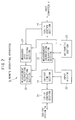
- a measuring room 1 is strictly controlled for room temperature, humidity, atmosphere, and so forth.
- a three-dimensional measuring apparatus 2 measures an object.
- the control apparatus 3 drives and controls the three-dimensional measuring apparatus 2.
- the host computer 4 transmits a measurement instruction to the control apparatus 3 and receives measured information therefrom.
- the operating panel 5 manually operates the three-dimensional measuring apparatus 2 through the control apparatus 3.
- the control apparatus 3 causes a probe 11 of the three-dimensional measuring apparatus 2 to move to and contact a measurement object corresponding to a measurement instruction or a part program received from the host computer 4 or a measurement instruction received from the operating panel 5. In addition, the control apparatus 3 obtains measured information corresponding to a touch signal of the probe 11.
- a TV camera 6 is disposed as a photographing device that monitors the measurement state of the three-dimensional measuring apparatus 2. Picture infonnation is transmitted from the TV camera 6 to the host computer 4.
- a operating room 7 is, for example, disposed at a remote position of the measuring room 1.
- a remote operating apparatus 9 and a CAD/CAT system 10 are disposed.
- the remote operating apparatus 9 is connected to the host computer 4 of the measuring room 1 through a communication network 8 such as a LAN (Local Area Network) or a public telephone circuit.
- the CAD/CAT system 10 is linked to the remote operating apparatus 9.
- the remote operating apparatus 9 has functions for displaying a measurement instruction screen, generating a measurement instruction (for example, an environment setup instruction such as measurement speed) corresponding to a instruction data that is input on the measurement instruction screen, generating a part program corresponding to a measurement element, transmitting the measurement instruction to the CAD/CAT system 10, and transmitting a part program generated on the CAD/CAT side to the host computer 4.
- data is communicated between the host computer 4 and the remote operating apparatus 9 by a communication protocol of TCP/IP (Transmission Control Protocol/Internet Protocol).
- TCP/IP Transmission Control Protocol/Internet Protocol
- Fig. 2 is a functional block diagram showing the remote operating apparatus 9 accomplished by computer hardware and relevant software.
- a measurement instruction generating section 21 generates a measurement instruction for the three-dimensional measuring apparatus in response to instruction information received from an input section 22.
- An arithmetic section 23 performs calculations necessary for the measurement instruction.
- a measurement instruction displaying section 24 generates and displays the measurement instruction screen for measurement instructing.
- a CAD/CAT link section 25 performs a link function such as activating, connecting, or switching the CAD/CAT system 10 corresponding to the measurement instruction.
- a TCP/IP control section 26 controls for transmitting/receiving the measurement instruction and measured information between the measurement instruction generating section 21 and the host computer 4 corresponding to the communication protocol of TCP/IP.
- the received measured information includes measured data error information, and environment setup data. These information are stored in a measured data receiving section 27. When necessary, these information are supplied to the arithmetic section 23. Thus, the arithmetic section 23 obtains the distance between two points, angle, and so forth.
- a TCP/IP control section 28 controls for transmitting/receiving the measurement instruction and part programs with the CAD/CAT system 10 corresponding to the communication protocol of TCP/IP.
- the above-described functions of the remote operating apparatus 9 are accomplished by for example a computer program.
- the program is provided as a proper recording medium.
- Fig. 3 is an example of the measurement instruction screen displayed on the measurement instruction displaying section 24 of the remote operating apparatus 9.
- the measurement instruction screen there are a file menu, an environment menu, a coordinate system menu, a measurement menu, a display menu, and a help menu as follows.
- the operator selects "speed designation" on the measurement instruction screen of the remote operating apparatus 9. Thereafter, the operator designates the moving velocity and measuring velocity of the probe 11 of the three-dimensional measuring apparatus 2 and then presses the run button.
- the remote operating apparatus 9 generates a part program as shown in Fig. 4A corresponding to the input conditions and transmits the part program to the host computer 4 through the communication network 8.
- the host computer 8 transmits the resultant data to the remote operating apparatus 9.
- the remote operating apparatus 9 displays the setup result on the measurement instruction screen as shown in Fig. 3.
- the operator When the operator measures a circle, he or she selects "circle measurement” icon on the measurement instruction screen, inputs a label name and the number of measurement points of the measured result, and presses the run button. The resultant condition is transmitted to the CAD/CAT system 10.
- the measurement instruction screen is switched to a screen of the CAD/CAT system 10.
- the screen of the CAD/CAT system 10 displays a figure corresponding to CAD data of the measurement object.
- the operator selects a circle to be measured.
- the operator sets up conditions such as an inner/outer circle and an approach direction of the measurement probe corresponding to a measurement instruction displayed on the screen and then selects measurement start.
- the CAD/CAT system 10 generates a part program that defines a measurement path and executes arithmetic instructions for measuring the designated circle as shown in Fig. 4B and transmits the part program to the remote operating apparatus 9.
- the remote operating apparatus 9 transmits the part program to the host computer 4 through the communication network 8 by the communication protocol of TCP/IP.
- the host computer 4 supplies the received part program to the control apparatus 3.
- the three-dimensional measuring apparatus 2 starts the measurement operation corresponding to the part program.
- the resultant measured data is transmitted to the remote operating apparatus 9 through the control apparatus 3, the host computer 4 and the communication network 8.
- the remote operating apparatus 9 stores the measured data to the measured data receiving section 27 and displays the measured data on the measurement instruction screen as shown in Fig. 3.
- the probe traveling path is generated by the CAD/CAT system 10
- the measurement object can be accurately measured regardless of the experience of the operator. For example, when a hole diameter is measured with three points, the probe 11 can be more accurately contacted to the measurement object at intervals of 120° than the case that the operator operates a joystick on the operating panel 5.
- the CAD/CAT system 10 may be constructed by use of a commercially available CAD.
- a module that generates a traveling path of the probe 11 is formed with Autocad (made by IBM) and added to the CAD menu, whereby the CAD/CAT system 10 can be structured.
- the control apparatus 3 suspends the measurement process and transmits error information to the host computer 4.
- the host computer 4 transmits the received error information to the remote operating apparatus 9 through the communication network 8.
- the remote operating apparatus 9 displays the detected error on the measurement instruction screen.
- the TV camera 6 is disposed so as to face the three-dimensional measuring apparatus 2.
- a picture photographed by the TV camera 6 is transmitted to the remote operating apparatus 9 through the host computer 4 and the communication network 8 by the communication protocol of TCP/IP.
- the picture photographed by the TV camera 6 is displayed in a window formed on the screen as shown in Fig.3.
- a part program file can be generated. Instructions for speed designation and circle measurement are issued as part programs to the control apparatus 3. Thus, when the control apparatus 3 designates a file name and enters into part program record mode, these instructions are recorded as part program files.
- the present invention is not limited to such a system. Instead, the present invention can be applied to a remote control measuring system with another measuring apparatus such as a shape measuring apparatus.
- a measurement instruction generated in response to an instruction data that is input on the measurement instruction screen of the remote operating apparatus, a part program, and so forth are transmitted to the host computer through a communication network, whereby the measurement operation is started up.
- the resultant measured information is immediately sent back to the remote operating apparatus and displayed on the measurement instruction screen thereof.
Abstract
Description
Claims (6)
- A remote control measuring system, comprising:a measuring apparatus;a control apparatus for controlling and driving said measuring apparatus corresponding to a measurement command and obtaining measured information of said measuring apparatus;a host computer for transmitting the measurement command to said control apparatus corresponding to a measurement instruction and receiving the measured information therefrom; anda remote operating apparatus for transmitting the measurement instruction to said host computer through a communication network and receiving the measured information therefrom,wherein said remote operating apparatus displays a measurement instruction screen, generates the measurement instruction in response to an input operation on the measurement instruction screen, transmits the measurement instruction to said host computer, and displays the measured information received from said host computer on the measurement instruction screen.
- A remote control measuring system, comprising:a measuring apparatus;a control apparatus for controlling and driving said measuring apparatus corresponding to a measurement command and obtaining measured information of said measuring apparatus;a host computer for transmitting the measurement command to said control apparatus corresponding to a measurement instruction and receiving the measured information therefrom;a remote operating apparatus for transmitting the measurement instruction to said host computer through a communication network and receiving the measured information therefrom; anda CAD/CAT (Computer Aided Design/Computer Aided Testing) system linked to said remote operating apparatus,wherein said remote operating apparatus has a measurement instruction screen displaying function and a CAD/CAT system connecting/switching function, andwherein said remote operating apparatus switches to a screen of said CAD/CAT system in response to an input operation on the measurement instruction screen, allows the operator to input a command on a figure displayed on the screen of said CAD/CAT system, transmits part programs corresponding to measurement elements generated in said CAD/CAT system to said host computer, and displays measured information received from said host computer to the measurement instruction screen.
- A remote control measuring system according to claim 2, wherein said remote operating apparatus and said CAD/CAT system mutually communicate with each other corresponding to a communication protocol of TCP/IP.
- A remote control measuring system according to any of the preceding claims, wherein said host computer and said remote operating apparatus mutually communicate with each other corresponding to a communication protocol of TCP/IP (Transmission Control Protocol/Internet Protocol).
- A remote control measuring system according to any of the preceding claims, further comprising:photographing means for photographing a measurement state of said measuring apparatus,wherein said host computer transmits picture information obtained by said photographing means to said remote operating apparatus through the communication network, andwherein said remote operating apparatus displays the received picture information on the measurement instruction screen.
- A remote control measuring system according to any of the preceding claims, wherein said measuring apparatus is a three-dimensional measuring apparatus.
Applications Claiming Priority (3)
| Application Number | Priority Date | Filing Date | Title |
|---|---|---|---|
| JP152621/97 | 1997-06-10 | ||
| JP15262197 | 1997-06-10 | ||
| JP9152621A JPH10339630A (en) | 1997-06-10 | 1997-06-10 | 3-dimension measuring system |
Publications (3)
| Publication Number | Publication Date |
|---|---|
| EP0884664A2 true EP0884664A2 (en) | 1998-12-16 |
| EP0884664A3 EP0884664A3 (en) | 1999-12-22 |
| EP0884664B1 EP0884664B1 (en) | 2004-08-18 |
Family
ID=15544388
Family Applications (1)
| Application Number | Title | Priority Date | Filing Date |
|---|---|---|---|
| EP98304484A Revoked EP0884664B1 (en) | 1997-06-10 | 1998-06-05 | Remote control measuring system |
Country Status (5)
| Country | Link |
|---|---|
| US (1) | US6009381A (en) |
| EP (1) | EP0884664B1 (en) |
| JP (1) | JPH10339630A (en) |
| CN (1) | CN1154897C (en) |
| DE (1) | DE69825677T2 (en) |
Cited By (7)
| Publication number | Priority date | Publication date | Assignee | Title |
|---|---|---|---|---|
| WO2002050621A2 (en) * | 2000-12-20 | 2002-06-27 | Siemens Aktiengesellschaft | Communication method |
| EP1233376A3 (en) * | 2001-02-20 | 2004-03-17 | Canon Kabushiki Kaisha | Information processing apparatus and method |
| EP1248169A3 (en) * | 2001-03-21 | 2004-08-25 | SCM GROUP S.p.A. | A woodworking machine tool and a built-in remote service system |
| EP1241455B1 (en) * | 2001-03-13 | 2005-08-10 | Tamtron OY | Weight measuring method and system |
| DE10108688B4 (en) * | 2001-02-23 | 2013-01-31 | Carl Zeiss Industrielle Messtechnik Gmbh | measuring device |
| CN116226951A (en) * | 2022-12-05 | 2023-06-06 | 中山市可讯科技有限公司 | Novel online plane measurement method and application thereof |
| CN116226951B (en) * | 2022-12-05 | 2024-04-30 | 中山市可讯科技有限公司 | Novel online plane measurement method and application thereof |
Families Citing this family (27)
| Publication number | Priority date | Publication date | Assignee | Title |
|---|---|---|---|---|
| JP3668375B2 (en) * | 1998-08-12 | 2005-07-06 | 株式会社ミツトヨ | Inline measurement system |
| JP4386979B2 (en) * | 1998-08-25 | 2009-12-16 | 株式会社ミツトヨ | Remote control measurement system |
| JP4387454B2 (en) * | 1998-08-25 | 2009-12-16 | 株式会社ミツトヨ | Remote control measurement system |
| US20030028501A1 (en) * | 1998-09-17 | 2003-02-06 | David J. Balaban | Computer based method for providing a laboratory information management system |
| US20030126258A1 (en) * | 2000-02-22 | 2003-07-03 | Conkright Gary W. | Web based fault detection architecture |
| US6957172B2 (en) | 2000-03-09 | 2005-10-18 | Smartsignal Corporation | Complex signal decomposition and modeling |
| AU2001283046A1 (en) * | 2000-08-01 | 2002-02-13 | Rensselaer Polytechnic Institute | Conducting remote instructor-controlled experimentation |
| GB0210990D0 (en) * | 2002-05-14 | 2002-06-19 | Rolls Royce Plc | Method of generating an inspection program and method of generating a visual display |
| US6931287B2 (en) * | 2002-09-03 | 2005-08-16 | Acu-Rite, Inc. | Remote console |
| JP2004158927A (en) * | 2002-11-01 | 2004-06-03 | Research Institute Of Biomolecule Metrology Co Ltd | Remote entrusted measurement system and remote entrusted measurement method |
| JP2004177192A (en) * | 2002-11-26 | 2004-06-24 | Dainippon Printing Co Ltd | Inspection device for defective height and inspection method for defective height |
| JP2004294311A (en) * | 2003-03-27 | 2004-10-21 | Nikon Corp | Picture image measuring instrument |
| US8275577B2 (en) | 2006-09-19 | 2012-09-25 | Smartsignal Corporation | Kernel-based method for detecting boiler tube leaks |
| US8311774B2 (en) | 2006-12-15 | 2012-11-13 | Smartsignal Corporation | Robust distance measures for on-line monitoring |
| US20080278143A1 (en) * | 2006-12-19 | 2008-11-13 | Lecroy Corporation | Remote Display and Control for Test and Measurement Apparatus |
| JP5859979B2 (en) * | 2010-01-14 | 2016-02-16 | ベンチャー ゲイン リミテッド ライアビリティー カンパニー | Health indicators based on multivariate residuals for human health monitoring |
| US8660980B2 (en) | 2011-07-19 | 2014-02-25 | Smartsignal Corporation | Monitoring system using kernel regression modeling with pattern sequences |
| US8620853B2 (en) | 2011-07-19 | 2013-12-31 | Smartsignal Corporation | Monitoring method using kernel regression modeling with pattern sequences |
| US9256224B2 (en) | 2011-07-19 | 2016-02-09 | GE Intelligent Platforms, Inc | Method of sequential kernel regression modeling for forecasting and prognostics |
| US9250625B2 (en) | 2011-07-19 | 2016-02-02 | Ge Intelligent Platforms, Inc. | System of sequential kernel regression modeling for forecasting and prognostics |
| CN102841047B (en) * | 2012-08-31 | 2015-07-01 | 深圳市华星光电技术有限公司 | Cleanness monitoring system and cassette |
| US9429416B2 (en) * | 2013-12-06 | 2016-08-30 | Tesa Sa | Accessory for coordinate measuring machine |
| JP2015141140A (en) * | 2014-01-29 | 2015-08-03 | 株式会社ミツトヨ | Remotely-operable measuring instrument and measuring system |
| JP7149485B2 (en) * | 2018-10-10 | 2022-10-07 | 株式会社東京精密 | Three-dimensional measurement result processing method and processing device, and three-dimensional measuring machine |
| JP7296186B2 (en) * | 2019-05-31 | 2023-06-22 | 株式会社ミツトヨ | Shape measurement system and its control method |
| JP7309458B2 (en) * | 2019-05-31 | 2023-07-18 | 株式会社ミツトヨ | Shape measurement system and its control method |
| JP6837109B2 (en) * | 2019-09-04 | 2021-03-03 | 株式会社ミツトヨ | Control system |
Citations (2)
| Publication number | Priority date | Publication date | Assignee | Title |
|---|---|---|---|---|
| WO1995021417A1 (en) * | 1994-02-02 | 1995-08-10 | Radical Advanced Technologies Corporation | Replicator system and method for digitizing the geometry of a physical object |
| WO1995028615A1 (en) * | 1994-04-19 | 1995-10-26 | Marposs Societa' Per Azioni | System for detecting linear dimensions and method for testing the system operability |
Family Cites Families (10)
| Publication number | Priority date | Publication date | Assignee | Title |
|---|---|---|---|---|
| US4789973A (en) * | 1985-08-22 | 1988-12-06 | Canon Kabushiki Kaisha | Recording/reproducing apparatus with dual display capability |
| GB2202659B (en) * | 1987-02-23 | 1991-07-17 | Mitutoyo Corp | Coordinate measuring instrument and method of generating pattern data concerning shape of work to be measured |
| JPH0290335A (en) * | 1988-09-28 | 1990-03-29 | Hitachi Ltd | Remote operation control system for computer system |
| JP2698685B2 (en) * | 1990-03-27 | 1998-01-19 | 株式会社東芝 | Computer system remote control device |
| US5220380A (en) * | 1990-08-10 | 1993-06-15 | Minolta Camera Kabushiki Kaisha | Control system for copying machines with improved communication function for centralized control unit |
| US5349675A (en) * | 1990-09-04 | 1994-09-20 | International Business Machines Corporation | System for directly displaying remote screen information and providing simulated keyboard input by exchanging high level commands |
| US5418730A (en) * | 1993-04-16 | 1995-05-23 | Brown & Sharp Manufacturing Company | Control axis mounted computer interface for coordinate measuring machines |
| JP3426293B2 (en) * | 1993-07-26 | 2003-07-14 | 株式会社リコー | Communication control device |
| US5712978A (en) * | 1994-12-30 | 1998-01-27 | Lucent Technologies Inc. | System for control of remote processors |
| US5726912A (en) * | 1996-09-06 | 1998-03-10 | Honeywell Iac | Control system monitor |
-
1997
- 1997-06-10 JP JP9152621A patent/JPH10339630A/en active Pending
-
1998
- 1998-06-03 US US09/089,353 patent/US6009381A/en not_active Expired - Lifetime
- 1998-06-05 EP EP98304484A patent/EP0884664B1/en not_active Revoked
- 1998-06-05 DE DE69825677T patent/DE69825677T2/en not_active Revoked
- 1998-06-10 CN CNB981098827A patent/CN1154897C/en not_active Expired - Fee Related
Patent Citations (2)
| Publication number | Priority date | Publication date | Assignee | Title |
|---|---|---|---|---|
| WO1995021417A1 (en) * | 1994-02-02 | 1995-08-10 | Radical Advanced Technologies Corporation | Replicator system and method for digitizing the geometry of a physical object |
| WO1995028615A1 (en) * | 1994-04-19 | 1995-10-26 | Marposs Societa' Per Azioni | System for detecting linear dimensions and method for testing the system operability |
Cited By (10)
| Publication number | Priority date | Publication date | Assignee | Title |
|---|---|---|---|---|
| WO2002050621A2 (en) * | 2000-12-20 | 2002-06-27 | Siemens Aktiengesellschaft | Communication method |
| WO2002050621A3 (en) * | 2000-12-20 | 2007-12-06 | Siemens Ag | Communication method |
| EP1233376A3 (en) * | 2001-02-20 | 2004-03-17 | Canon Kabushiki Kaisha | Information processing apparatus and method |
| US6917842B2 (en) | 2001-02-20 | 2005-07-12 | Canon Kabushiki Kaisha | Information processing apparatus and method |
| US7054701B2 (en) | 2001-02-20 | 2006-05-30 | Canon Kabushiki Kaisha | Information processing apparatus and method |
| DE10108688B4 (en) * | 2001-02-23 | 2013-01-31 | Carl Zeiss Industrielle Messtechnik Gmbh | measuring device |
| EP1241455B1 (en) * | 2001-03-13 | 2005-08-10 | Tamtron OY | Weight measuring method and system |
| EP1248169A3 (en) * | 2001-03-21 | 2004-08-25 | SCM GROUP S.p.A. | A woodworking machine tool and a built-in remote service system |
| CN116226951A (en) * | 2022-12-05 | 2023-06-06 | 中山市可讯科技有限公司 | Novel online plane measurement method and application thereof |
| CN116226951B (en) * | 2022-12-05 | 2024-04-30 | 中山市可讯科技有限公司 | Novel online plane measurement method and application thereof |
Also Published As
| Publication number | Publication date |
|---|---|
| DE69825677T2 (en) | 2005-08-18 |
| EP0884664B1 (en) | 2004-08-18 |
| US6009381A (en) | 1999-12-28 |
| DE69825677D1 (en) | 2004-09-23 |
| CN1209540A (en) | 1999-03-03 |
| EP0884664A3 (en) | 1999-12-22 |
| JPH10339630A (en) | 1998-12-22 |
| CN1154897C (en) | 2004-06-23 |
Similar Documents
| Publication | Publication Date | Title |
|---|---|---|
| EP0884664B1 (en) | Remote control measuring system | |
| US5872594A (en) | Method for open loop camera control using a motion model to control camera movement | |
| US6208104B1 (en) | Robot control unit | |
| US4956790A (en) | Instruction system of remote-control robot | |
| WO2015167080A1 (en) | Unmanned aerial vehicle control apparatus and method | |
| JP2001142512A (en) | Remote operation system for robot | |
| MXPA06013936A (en) | Method and system for wide area security monitoring, sensor management and situational awareness. | |
| CN110977981A (en) | Robot virtual reality synchronization system and synchronization method | |
| JPH05149966A (en) | Control unit | |
| JP2002010240A (en) | Monitoring system | |
| US6983419B1 (en) | Communication apparatus, its control method, and storage medium | |
| JPH08368B2 (en) | Robot remote control device | |
| JPH08504543A (en) | Camera control method and apparatus | |
| JPH1034570A (en) | Robot remote control system | |
| JPH09261618A (en) | Remote controller | |
| JPH11275667A (en) | Remote control device and its communication control method | |
| JP2634880B2 (en) | Robot remote control device | |
| KR20010076786A (en) | Remote-Controlled Robot System and Method using VR technology | |
| CN114239884A (en) | Robot operation and maintenance method and system | |
| JP2001315080A (en) | Remote place observation device | |
| CN113093753A (en) | Method, device, terminal and storage medium for remotely controlling multiple robots on same screen | |
| JP2021170386A (en) | Robot controller and robot control method | |
| JP2741555B2 (en) | Monitor device in image processing device | |
| JP2000165833A (en) | Substitute image communication system and method | |
| KR20140008659A (en) | Teaching pendant built-in system monitoring device and method thereof |
Legal Events
| Date | Code | Title | Description |
|---|---|---|---|
| PUAI | Public reference made under article 153(3) epc to a published international application that has entered the european phase |
Free format text: ORIGINAL CODE: 0009012 |
|
| AK | Designated contracting states |
Kind code of ref document: A2 Designated state(s): DE FR GB |
|
| AX | Request for extension of the european patent |
Free format text: AL;LT;LV;MK;RO;SI |
|
| PUAL | Search report despatched |
Free format text: ORIGINAL CODE: 0009013 |
|
| AK | Designated contracting states |
Kind code of ref document: A3 Designated state(s): AT BE CH CY DE DK ES FI FR GB GR IE IT LI LU MC NL PT SE |
|
| AX | Request for extension of the european patent |
Free format text: AL;LT;LV;MK;RO;SI |
|
| 17P | Request for examination filed |
Effective date: 20000516 |
|
| AKX | Designation fees paid |
Free format text: DE FR GB |
|
| 17Q | First examination report despatched |
Effective date: 20030207 |
|
| GRAP | Despatch of communication of intention to grant a patent |
Free format text: ORIGINAL CODE: EPIDOSNIGR1 |
|
| GRAS | Grant fee paid |
Free format text: ORIGINAL CODE: EPIDOSNIGR3 |
|
| GRAA | (expected) grant |
Free format text: ORIGINAL CODE: 0009210 |
|
| AK | Designated contracting states |
Kind code of ref document: B1 Designated state(s): DE FR GB |
|
| REG | Reference to a national code |
Ref country code: GB Ref legal event code: FG4D |
|
| REF | Corresponds to: |
Ref document number: 69825677 Country of ref document: DE Date of ref document: 20040923 Kind code of ref document: P |
|
| PLAQ | Examination of admissibility of opposition: information related to despatch of communication + time limit deleted |
Free format text: ORIGINAL CODE: EPIDOSDOPE2 |
|
| PLAR | Examination of admissibility of opposition: information related to receipt of reply deleted |
Free format text: ORIGINAL CODE: EPIDOSDOPE4 |
|
| PLBQ | Unpublished change to opponent data |
Free format text: ORIGINAL CODE: EPIDOS OPPO |
|
| PLBI | Opposition filed |
Free format text: ORIGINAL CODE: 0009260 |
|
| PLAQ | Examination of admissibility of opposition: information related to despatch of communication + time limit deleted |
Free format text: ORIGINAL CODE: EPIDOSDOPE2 |
|
| PLAR | Examination of admissibility of opposition: information related to receipt of reply deleted |
Free format text: ORIGINAL CODE: EPIDOSDOPE4 |
|
| PLAX | Notice of opposition and request to file observation + time limit sent |
Free format text: ORIGINAL CODE: EPIDOSNOBS2 |
|
| PLBQ | Unpublished change to opponent data |
Free format text: ORIGINAL CODE: EPIDOS OPPO |
|
| PLAB | Opposition data, opponent's data or that of the opponent's representative modified |
Free format text: ORIGINAL CODE: 0009299OPPO |
|
| 26 | Opposition filed |
Opponent name: CARL ZEISS INDUSTRIELLE MESSTECHNIK GMBH Effective date: 20050502 |
|
| ET | Fr: translation filed | ||
| R26 | Opposition filed (corrected) |
Opponent name: CARL ZEISS INDUSTRIELLE MESSTECHNIK GMBH Effective date: 20050502 |
|
| PLAF | Information modified related to communication of a notice of opposition and request to file observations + time limit |
Free format text: ORIGINAL CODE: EPIDOSCOBS2 |
|
| PLBB | Reply of patent proprietor to notice(s) of opposition received |
Free format text: ORIGINAL CODE: EPIDOSNOBS3 |
|
| PLAY | Examination report in opposition despatched + time limit |
Free format text: ORIGINAL CODE: EPIDOSNORE2 |
|
| PLAH | Information related to despatch of examination report in opposition + time limit modified |
Free format text: ORIGINAL CODE: EPIDOSCORE2 |
|
| PLAH | Information related to despatch of examination report in opposition + time limit modified |
Free format text: ORIGINAL CODE: EPIDOSCORE2 |
|
| PLBC | Reply to examination report in opposition received |
Free format text: ORIGINAL CODE: EPIDOSNORE3 |
|
| PGFP | Annual fee paid to national office [announced via postgrant information from national office to epo] |
Ref country code: GB Payment date: 20090603 Year of fee payment: 12 Ref country code: DE Payment date: 20090529 Year of fee payment: 12 |
|
| RDAF | Communication despatched that patent is revoked |
Free format text: ORIGINAL CODE: EPIDOSNREV1 |
|
| RDAG | Patent revoked |
Free format text: ORIGINAL CODE: 0009271 |
|
| STAA | Information on the status of an ep patent application or granted ep patent |
Free format text: STATUS: PATENT REVOKED |
|
| 27W | Patent revoked |
Effective date: 20090619 |
|
| PGFP | Annual fee paid to national office [announced via postgrant information from national office to epo] |
Ref country code: FR Payment date: 20090611 Year of fee payment: 12 |