EP0889613A2 - Information processing apparatus for and method of transmitting and/or receiving broadcast signal - Google Patents
Information processing apparatus for and method of transmitting and/or receiving broadcast signal Download PDFInfo
- Publication number
- EP0889613A2 EP0889613A2 EP98305274A EP98305274A EP0889613A2 EP 0889613 A2 EP0889613 A2 EP 0889613A2 EP 98305274 A EP98305274 A EP 98305274A EP 98305274 A EP98305274 A EP 98305274A EP 0889613 A2 EP0889613 A2 EP 0889613A2
- Authority
- EP
- European Patent Office
- Prior art keywords
- information
- distributed
- data
- multiplexing
- entity
- Prior art date
- Legal status (The legal status is an assumption and is not a legal conclusion. Google has not performed a legal analysis and makes no representation as to the accuracy of the status listed.)
- Granted
Links
Images


Classifications
-
- H—ELECTRICITY
- H04—ELECTRIC COMMUNICATION TECHNIQUE
- H04L—TRANSMISSION OF DIGITAL INFORMATION, e.g. TELEGRAPHIC COMMUNICATION
- H04L1/00—Arrangements for detecting or preventing errors in the information received
- H04L1/004—Arrangements for detecting or preventing errors in the information received by using forward error control
- H04L1/0056—Systems characterized by the type of code used
- H04L1/0057—Block codes
-
- H—ELECTRICITY
- H04—ELECTRIC COMMUNICATION TECHNIQUE
- H04L—TRANSMISSION OF DIGITAL INFORMATION, e.g. TELEGRAPHIC COMMUNICATION
- H04L1/00—Arrangements for detecting or preventing errors in the information received
- H04L1/004—Arrangements for detecting or preventing errors in the information received by using forward error control
- H04L1/0045—Arrangements at the receiver end
-
- H—ELECTRICITY
- H04—ELECTRIC COMMUNICATION TECHNIQUE
- H04L—TRANSMISSION OF DIGITAL INFORMATION, e.g. TELEGRAPHIC COMMUNICATION
- H04L1/00—Arrangements for detecting or preventing errors in the information received
- H04L1/004—Arrangements for detecting or preventing errors in the information received by using forward error control
- H04L1/0056—Systems characterized by the type of code used
- H04L1/0064—Concatenated codes
- H04L1/0065—Serial concatenated codes
Definitions
- the present invention relates to an information processing apparatus and method and, more particularly, to an information processing apparatus for and method of processing information with a description format used in a multimedia network.
- a so-called "visible radio receiver a radio receiver that can display received character information
- a device of this type has high portability and a very simple circuit, and can receive various kinds of information as long as it can receive an FM wave.
- the information transmitted using FM audio broadcast include news, weather forecasts, and the like. Although such information can be received via a so-called multimedia network, they can be more easily obtained by the "visible radio receiver".
- the "visible radio receiver” has higher portability than normal multimedia terminals.
- Such receiver can only receive simple character information such as weather forecast information and the like as currently available services, but can neither receive nor store information in a description format used in a multimedia network, which format can be easily handled by a personal computer (PC), in addition to the character information.
- PC personal computer
- Normal data or data that can be processed by a PC may be transmitted in place of the character information.
- data may be merely broadcasted in place of the character information, its reliability cannot be maintained, and this results in unwanted confusion upon processing of such data.
- Such data may be transmitted in a system quite different from the current broadcast.
- the existing system itself must then be reexamined, and this is impractical.
- the broadcasting station requires considerably large-scale equipment.
- the present invention has been made in consideration of the above situation, and has as an object to provide a novel information processing apparatus and method, which can multiplex data, which can be easily processed by a versatile processor, on a broadcast signal and can transmit the multiplexed signal with high reliability and without requiring large-scale equipment.
- an information processing apparatus/method which error detection or correction encodes information to be distributed in a description format used in a multimedia network, and which error detection or correction encodes at least a portion in a header in the information to be distributed with higher redundancy than an entity in the information to be distributed, multiplexes the encoded information to be distributed in a broadcast signal, and transmits the multiplexed signal.
- an information processing apparatus/method which inputs information to be distributed in a description format used in a multimedia network, multiplexes the information to be distributed in a broadcast signal, and transmits the multiplexed signal, and which transmits a portion of a header in the information to be distributed at least a plurality of number of times while an entity in the information to be distributed is transmitted.
- an information processing apparatus/method which error detection or correction encodes information to be distributed in a description format used in a multimedia network, multiplexes the encoded information to be distributed in a broadcast signal, and transmits the multiplexed signal, and which can transmit a plurality of kinds of information as an entity in the information to be distributed, and uses different error detection or correction ability in correspondence with the kind of information.
- an information processing apparatus/method which inputs information to be distributed in a description format used in a multimedia network, multiplexes the information to be distributed in a broadcast signal, and transmits the multiplexed signal, and in which the information to be distributed is transmitted as an entity in a data format used for multiplexing another information in a description format, which is not used in the multimedia network, in an FM audio signal, the data format forms an error correction code, and a header of the information to be distributed forms an error correction code different from the error correction code.
- an information processing apparatus/method which receives a broadcast signal obtained by multiplexing information to be distributed in a description format used in a multimedia network and an error correction or detection check code added for at least partial information of the information to be distributed, as an entity of a data format which is used for multiplexing predetermined information in an FM audio signal and includes an error correction check code, and performs an error correction or detection processing of the information to be distributed using the error correction check code and the error correction or detection check code, and which executes the processing based on the error correction check code and processing based on the error correction or detection check code at different timings.
- an information processing apparatus/method which receives a broadcast signal obtained by multiplexing information to be distributed in a description format, used in a multimedia network, as an entity of a data format used for multiplexing predetermined information in an FM audio signal, and stores the information to be distributed in storage means, and which informs that the received information to be distributed is stored in the storage means and is not output to an external device.
- an information processing apparatus/method which receives a broadcast signal obtained by multiplexing information to be distributed in a description format, used in a multimedia network, as an entity of a data format used for multiplexing first character information in an FM audio signal, and displays second character information using display means for displaying the first character information when the information to be distributed has the second character information.
- an information processing apparatus/method which receives a broadcast signal obtained by multiplexing information to be distributed in a description format, used in a multimedia network, as an entity of a data format used for multiplexing character information in an FM audio signal, and stores the information to be distributed in storage means, and which executes a command for displaying information stored in the storage means, and a command for outputting the stored information to an external device at different timings.
- an information processing apparatus/method which inputs information data, and a check code for correcting an error of the information data, detects an error state of the information data, sets an allowable error state of the information data, and controls processing for the input information data in accordance with results in the setting step and the detection step.
- Fig. 1 is a schematic block diagram showing the arrangement of a broadcast signal transmitter according to the present invention, and shows the transmitter which is equipped in a radio broadcasting station.
- a personal computer (PC) 3 has an operation unit 1 and display unit 2. This PC is connected to a bus B, and can receive data from this bus B. Also, an image memory 4, format memory 5, Internet server 6, JPEG encoder 7, HTML (HyperText Markup Language) memory 8, error correction code (ECC) encoder 9, and the like are connected to the bus B.
- image memory 4 format memory 5
- JPEG encoder 7 HTML (HyperText Markup Language) memory 8
- ECC error correction code
- a matrix circuit 11 receives R and L signals, and outputs their sum signal (L + R) and difference signal (L - R).
- the sum signal (L + R) is input to one input terminal of a switch 12.
- the other input terminal of this switch 12 receives a monaural signal (M), and outputs the monaural signal (M) in case of monaural broadcast or the sum signal (L + R) in case of stereophonic broadcast.
- a pilot signal generation circuit 16 generates a pilot signal of a predetermined frequency in response to switching of the switch 12.
- the frequency of the difference signal (L - R) is converted by a balanced modulation (BM) circuit 13, and is multiplexed on the output from the switch 12 and the pilot signal by a multiplexing circuit 17.
- BM balanced modulation
- the sum signal (L + R) or monaural signal (M) is allocated at the baseband side, and the difference signal (L - R) is frequency-converted by a carrier wave of 38 kHz using the BM circuit 13 and is allocated in a frequency band shown in Fig. 2.
- a bandpass filter (BPS) for cutting off unwanted frequency bands is inserted at the output stage of the BM circuit 13.
- digital data is input to a D/A converter 14 via the above-mentioned bus B, and is converted into a binary analog signal. Furthermore, this analog signal is input to a BM circuit 15 and is frequency-converted by a carrier wave of 76 kHz to allocate it at a frequency higher than those of the audio signals and pilot signal.
- the multiplexing circuit 17 can frequency-multiplex that analog signal and other signals.
- the multiplexed signal is originally standardized for teletext data, and this embodiment discloses an example of a technique for transmitting data in the HTML format used in a WWW (World Wide Web) as a broadcast wave, using this multiplexed signal.
- a 16-bit prefix field, 160-bit character data, and a 14-bit CRC code follow a 16-bit block identification code, and an 82-bit parity check code is added for a total of 190 bits of the prefix field, character data, and CRC code, thus forming an error correction code having a code length of 272 bits.
- the block identification code is assigned as sync data for identifying the block boundary, and the location of a block is identified by this code to establish block synchronization.
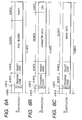
- the 16-bit prefix field has the format shown in Fig. 4, and contains 4-bit service identification data, 1-bit decoding identification data, 1-bit information end data, 2-bit update data, a 4-bit data group number, and a 4-bit data packet number.
- the service identification data indicates the contents of a teletext service, i.e., the type (character, figure information, additional information, auxiliary signal, operation signal) of the program contents and transmission mode.
- Ten kinds of services have already been defined as the service identification data in the teletext, and the remaining six kinds remain undefined.
- a service for broadcasting data in the HTML format is defined as one of these six kinds. In practice, "0111”, “1000”, “1001", “1010", and the like are undefined data.
- the decoding identification data distinguishes between a case wherein error correction requires decoding in the row direction in Fig. 3 alone, and a case wherein error correction requires decoding of the product code in the row and column directions.
- the information end data identifies whether or not the block of interest is the last block of each data group, and the update data indicates the number of times of update of the contents of the data group of interest.
- the service identification bit indicates that the data group of interest is a program of data in the HTML format, and whether or not the data group of interest has been updated for data of the identical previous group using the update data.
- Fig. 5 shows the format of data to be transmitted in this embodiment, which format complies with that of the teletext.
- 4-bit identification data (DID) follows immediately after a prefix field.
- This data DID indicates if data of the block of interest is character data complying with the HTML format, image data, a header, or the like, and also defines its compression method if the character data or image data is compressed data. If this data DID suffers errors during transmission, nonsense data is reconstructed.
- a dedicated CRC code is added after this identification data DID, thus reliably detecting code errors in the identification data.
- 168-bit actual data can be transmitted in each block.
- an HTML header field, character data, and image data have different data formats.
- Figs. 6A to 6C show these data formats.
- 32 bits of the 168-bit data are assigned to parity that forms an error correction code independently of the 82-bit parity shown in Fig. 5. More specifically, the above-mentioned 82-bit parity is added to 190-bit information data to form a 272-bit error correction code, but this 32-bit parity is added to a 16-bit program code, 16-bit packet code, and 104-bit HTML header to form a 168-bit error correction code.
- the program code is data which is the same as the data group number in the teletext, and defines the program number (of one of 2 16 programs) of HTML data to be broadcasted.
- the packet code indicates the serial number in each program of each data block (packet), and can add one of 2 16 numbers so that packet numbers can be assigned to a considerably long document or very sophisticated image.
- a block (packet) containing actual information data (entity) such as character data, image data, and the like will be described below.
- information data entity
- image data can be transmitted using all the 134 bits, as shown in Fig. 6C.
- HTML data As the headers of HTML data, a request method, general message header (general header), request header, response header, entity header, and the like are known. As may be apparent from the above description, a broadcast application like in this embodiment requires at least a general header, response header, and entity header.
- header data to be sent include Date (generation date and time of a message) as a general header, Server (server software name) and WWW-Authenticate (authentication method used when the server uses an authentication mechanism) as a response header, Content-length (entity body size), Content-Encoding (schemes of compressing, encrypting, and packaging an object), Content-Transfer-Encoding (encode scheme used upon actual data transfer), and the like as the entity headers.
- the data volume to be sent amounts to 100 characters as 8-bit alphabet data, i.e., about 800 bits.
- the data volume of this header field varies depending on programs. As shown in Fig. 6A, since 104-bit data can be transmitted per block, the data volume of the headers roughly amounts to less than 10 blocks.
- the data volume of character data also varies depending on the length of one program. For example, assuming that a device has a display LCD screen size of approximately 480 ⁇ 240 dots, each of which is 0.24 mm, and displays 12-point (5 mm ⁇ 5 mm) font data, character data for nearly 23 ⁇ 11 characters are to be sent per frame.
- the total number of bits before compression coding is (76,800 + 76,800/4 + 76,800/4) ⁇ 8, i.e., 384 kbits.
- this data is compressed to about 50 kbits by JPEG, as will be described later.
- image data for one field can be transmitted using about 290 blocks.
- Fig. 7 shows a data matrix obtained by rewriting that shown in Fig. 5 in accordance with the order of data to be actually transmitted by the transmitter of this embodiment.
- the operation of the transmitter of this embodiment will be explained below with reference to Fig. 7, and the flow chart in Fig. 8 that shows the operation of the computer 3.
- step S1 When the user commands the computer 3 to multiplex HTML data on a broadcast signal by operating the operation unit 1, the computer 3 displays a guidance on the display unit 2 to direct the user to input at the operation unit 1, and starts the processing according to Fig. 8 (step S1).
- the user inputs characters at the operation unit 1 or calls a desired HTML file from the Internet server 6 and stores it in the HTML memory 8 via the bus B while observing the guidance on the display unit 2.
- the user wants to input image data he or she calls desired screen data from the Internet server 6 as bitmap data, and stores it in the image memory 4 via the bus B. Since this series of operations are not directly associated with the present invention, they are summarized as an input subroutine (step S2) in the flow chart in Fig. 8.
- HTML header data stored in the HTML memory 8 is transferred to the ECC encoder 9 in accordance with an instruction from the computer 3 to start formation of 32-bit parity for a 104-bit header shown in Fig. 6C (step S3).
- the ECC encoder 9 incorporates a 16-bit RISC processor and the like, and can form an error correction code without any processing by the computer 3. Hence, while the computer 3 is executing the processing in step S4 and the subsequent steps in the flow chart in Fig. 8, the ECC encoder 9 parallelly calculates parity.
- step S4 processing for adding a 14-bit CRC code to 122-bit character data in Fig. 6B is done in the computer 3 (step S5).
- step S6 the processing for adding the CRC code is interrupted, and image data stored in the image memory 4 is supplied to the JPEG encoder 7 and is compressed by JPEG (step S7).
- this JPEG encoder 7 comprises a hardware chip, and can process parallel to the CRC formation in step S5.
- the JPEG-compressed data HTML header data with parity, character data added with a CRC code, and the like begin to be written in the format memory 5 (step S8).
- the individual data are written at locations according to the transmission format shown in Fig. 7.
- transmission starts from blocks that store the header.
- the first 13 blocks and the 137th to 149th blocks sent include only data blocks without any parity blocks.
- Blocks including the header data are successively transmitted from the first and 137th blocks, and when the data volume including the header exceeds 136 blocks, the header blocks are transmitted repetitively.
- the receiver side can obtain HTML header data with higher reliability earlier.
- the ECC encoder 9 calculates an 82-bit parity for 190-bit data including an HTML data header and 32-bit parity stored in the format memory 5 and a 288-bit data block obtained by adding a block identification code to these 272 bits is output in step S10.
- the 190-bit data includes a group identification code (DID), 2-bit CRC, 16-bit program code (PGC), packet code (PKC), the above-mentioned prefix (PFX), and the like, as shown in Fig. 6A.
- step S11 image or character data blocks are transmitted (step S12).
- step S12 character data blocks are sent first, which are followed by image data blocks.
- this transmission order depends on the configuration of the HTML file to be actually transmitted.
- step S13 the ECC encoder 9 starts calculations upon completion of data write in the format memory in step S9, and the calculated parity data are sequentially written in the format memory 5.
- step S16 After the parity block is transmitted, it is checked if the next block to be transmitted is the first or 137th block in the data matrix shown in Fig. 7 (step S16). If NO in step S16, it is checked if the data to be transmitted has come to an end (step S17). If NO in step S17, transmission of two blocks and one parity blocks repeats itself in steps S12 to S15.
- step S10 If the next block to be transmitted is the first or 137th block, the flow returns to step S10 to successively transmit header blocks again. This operation repeats itself until it is detected in step S17 that the data to be transmitted has come to an end. When there is no more data to send, the processing ends (step S18).
- the transmission data which are sequentially output from the bus B to the D/A converter 14 according to the data format shown in Fig. 7 are multiplexed with an FM audio signal by the multiplexing circuit 17, as described above, and the multiplexed signal is FM-modulated by a broadcast carrier using an FM modulation circuit 18. The modulated signal is then transmitted as a broadcast wave via a transmission control circuit 19.
- the transmitter of this embodiment can transmit HTML data while maintaining compatibility with the character data transmission function of a conventional FM radio broadcast.
- an error correction code is added by setting the redundancy of the HTML header higher than other data, and the error correction code used in conventional teletext is also used.
- the header of HTML data can have reliability equivalent to that obtained when the HTML data is transmitted via another network.
- burst errors unique to a broadcast wave can be coped with by transmitting the header a plurality of number of times, and high reliability can be assured as a whole.
- the required data can be transmitted with minimum redundancy, and high reliability can be guaranteed as a whole.
- a receiver of the present invention which receives the above-mentioned broadcast signal will be described in detail below.
- Fig. 9 shows the schematic arrangement of a reception system that receives data transmitted by the transmitter shown in Fig. 1.
- the system includes an FM broadcasting station 1000, a portable computer 1001 such as a sub notebook personal computer, or the like, and a portable receiver 1002 having an FM broadcast reception function.
- the portable receiver 1002 comprises an interface complying with PCMCIA (which is an international standard for memory cards and I/O cards (modem, LAN, and SCSI cards, and the like), and can be connected to a personal computer.
- PCMCIA which is an international standard for memory cards and I/O cards (modem, LAN, and SCSI cards, and the like)
- Information data transmitted by means of an FM broadcast wave from the FM broadcasting station 1000 is received by the portable receiver 1002, which decodes and displays the received data.
- the portable receiver 1002 When the portable receiver 1002 is connected to the portable computer 1001, the received information data is decoded by the portable computer 1001 and is displayed on a display unit or is stored in a recording medium.
- Fig. 10 is a perspective view showing the outer appearance of the portable receiver 1001.
- a portable receiver main body 101 has manual operation keys 102, 103, and 104 which are respectively used for issuing a display command and external output command, and selecting a broadcasting station. These keys correspond to an operation unit 98 shown in Fig. 11 (to be described later).
- the main body 101 also has a retractable antenna 51, a pair of loudspeakers 93 and 94 which can output stereophonic audio signals, a flat panel display 96, an external interface 80 complying with PCMCIA, and an indicator 99 indicating that HTML format data which has not been output to external equipment is stored in the main body after reception.
- Fig. 11 is a block diagram showing the internal arrangement of the portable receiver 1001.
- a broadcast wave received at the antenna 51 is tuned by a reception unit 52, and is detected by an FM detection circuit 53 to be converted into a multiplexed signal shown in Fig. 2.
- a bandpass filter (BPF) 54 separates the above-mentioned pilot signal, and supplies the separated pilot signal to a detection circuit 55.
- the output from the detection circuit 55 is compared with a predetermined threshold value by a comparison circuit 56, thus determining based on the comparison result if the broadcasted audio signal is a stereophonic or monaural signal.
- a low-pass filter (LPF) 60 extracts a baseband signal shown in Fig. 2, and supplies the extracted signal to a matrix circuit 59 as a monaural signal or the sum signal of stereophonic audio signals.
- a BPF 57 extracts a signal carried by a carrier wave of 38 kHz, and the extracted signal is converted to a baseband signal, i.e., the difference signal of the stereophonic audio signals by a balanced modulation (BM) circuit 58. After that, the difference signal is supplied to the matrix circuit 59.
- the matrix circuit 59 outputs right (R) and left (L) signals of the stereophonic audio signals, and these signals are output via switches 61 and 62 controlled by the output from the comparison circuit 56.
- both the switches 61 and 62 output the audio signal output from the LPF 60, thus similarly outputting monaural audio signals.
- the audio signals output from the switches 61 and 62 are output from the loudspeakers 93 and 94 via amplifiers 91 and 92, respectively.
- the above-mentioned data signal multiplexed on a carrier of 76 kHz is separated by a BPF 72, and is converted by a BM circuit 73 into a signal corresponding to a data sequence in the data format shown in Fig. 7.
- This signal is supplied to a clock extraction circuit 71 to form free-running clocks, and is converted into digital data by an A/D converter 74 using these clocks.
- the digital data is supplied to a known data detection circuit 75 to obtain original digital data.
- the data detection circuit 75 is comprised of a known integral detection circuit, equivalent circuit, a decoding circuit using partial response, and the like.
- Data detected by the data detection circuit 75 are output onto a reception bus RB as a data sequence, and are stored in a reception memory 77 under the control of a CPU 81.
- An ECC decoding circuit 76 accesses the data in the reception memory 77 under the control of the CPU 81, and performs error correction using the above-mentioned product code parity. Note that this error correction is performed using 82-bit parity in units of data blocks, and subsequently, error correction is performed using 82-bit parities distributed in the vertical direction in Fig. 7.
- the error-corrected character information is transferred to a storage memory 78.
- the character data in the storage memory 78 is written in a display memory 95 while being converted into display codes, and characters are displayed on the display 96.
- Fig. 12 is a flow chart for explaining the operation upon reception of the above-mentioned HTML data by the receiver of this embodiment, and that operation will be explained below with reference to this flow chart.
- step S101 When the reception unit 52 begins to receive data (step S101), data detected by the data detection circuit 75 are output onto the reception bus RB as a data sequence corresponding to the data format shown in Fig. 7, and are stored in the reception memory 77 under the control of the CPU 81 according to the format shown in Fig. 7 (step S102).
- the ECC decoding circuit 76 When data for one line (one data block) in the data matrix of Fig. 7 are stored in the reception memory 77 (step S103), the ECC decoding circuit 76 begins to access the data in the reception memory 77 under the control of the CPU 81. More specifically, error correction processing is executed using 82-bit outer code parity in units of data blocks (step S104).
- steps S103 and S104 repeat themselves until the entire data matrix shown in Fig. 7 is stored in the reception memory.
- the ECC decoding circuit 76 After the entire data matrix in Fig. 7 has been stored (step S106), the ECC decoding circuit 76 begins to access the data in the reception memory 77 again. At this timing, error correction processing is made using 82-bit inner code parities distributed in the data matrix in Fig. 7 in the vertical direction (step S107).
- step S108 Upon completion of the processing for one data matrix using the outer and inner code parities, the data are transferred from the reception memory 77 to the storage memory 78, and it is checked if all the data to be received have been received (step S108). If YES in step S108, the above-mentioned indicator 99 is turned on, i.e., lighted (step S109), thus ending the processing (step S110).
- Fig. 13 is a flow chart for explaining the operation executed upon depression of the above-mentioned display command switch 102 when the aforementioned HTML data are stored in the receiver of this embodiment, and that operation will be explained below with reference to this flow chart.
- step S121 the data stored in the storage memory 78 begin to be scanned under the control of the CPU 81 (step S122). This scan is done in units of lines, and the stored data for each line are processed under the control of the CPU 81.
- the CPU 81 monitors if the data of each line that have been subjected to error correction processing using a product code are character data, image data, or header data. If the line data to be processed are character data (step S123), the CPU 81 supplies the line data to the ECC decoding circuit 76 to detect the presence/absence of errors using a 14-bit CRC code shown in Fig. 6B (step S124). If no errors are detected, the character data are mapped into bitmap data, which are written in the display memory 95 (step S127).
- step S125 if the line data to be processed are image data (step S125), since the portable receiver of this embodiment cannot display any image, characters representing image data reception are generated (step S126), and bitmap data of these characters are written in the display memory 95 in step S127.
- step S1228 Upon completion of scanning of all the lines (step S128), the bitmap data stored in the display memory 95 are displayed as characters on the display 96 (step S129), thus ending the processing (step S130). If the line data to be processed are HTML header data, since this portable receiver cannot use them, these data are neither subjected to error correction processing nor written in the display memory 95.
- Fig. 14 is a flow chart for explaining the operation executed upon depression of the external output command switch 103 when the aforementioned HTML data are stored in the receiver of this embodiment, and that operation will be explained below with reference to this flow chart.
- step S141 If the external output command switch 103 is turned on (step S141), the data stored in the storage memory 78 begin to be scanned under the control of the CPU 81 (step S142). This scan is done in units of lines, and the stored data for each line are processed under the control of the CPU 81.
- the CPU 81 monitors if the data of each line that have been subjected to error correction processing using a product code are character data, image data, or header data.
- step S143 If the line data to be processed are character data (step S143), the presence/absence of errors is detected using the 14-bit CRC code shown in Fig. 6B as in case of the display command (step S144). If no errors are detected, the character data are directly output to external equipment such as a PC in units of lines of the data matrix shown in Fig. 7 via an external I/F 80 which complies with PCMCIA (step S147).
- external equipment such as a PC in units of lines of the data matrix shown in Fig. 7 via an external I/F 80 which complies with PCMCIA
- the line data to be processed are image data
- the image data are output to the PC or the like via the I/F 80 without any processing.
- the line data to be processed are HTML header data (step S145)
- error correction processing is performed using 32-bit parity shown in Fig. 6A, and data which have been subjected to error correction twice are output to the external equipment in units of lines via the I/F 80.
- step S148 Upon completion of scanning of all the lines (step S148), the data matrix stored in the storage memory is deleted or overwrite on this matrix is permitted, and the indicator 99 is turned off (step S149), thus ending the processing (step S150).
- the portable receiver of this embodiment upon receiving data, upon displaying received data, or upon outputting the received data to external equipment, the portable receiver of this embodiment performs only error detection or correction required for each operation, and does not perform any unnecessary processing, thus preventing the receiver from performing unwanted operations.
- the received data are stored, and the indicator which indicates that the received data have not been output is turned on. Hence, the operator can easily recognize such state, and the received data can be prevented from being wasted.
- the display device and display command switch which are used for displaying the conventional teletext character data can be directly used for displaying characters received as data in the HTML format. Hence, the above-mentioned composite functions can be implemented without increasing the receiver size.
- the image data supplied to the PC are reconstructed into original image data by a JPEG decoder installed in the PC, and are processed according to links recognized based on the header.
- the receiver 1002 When the receiver 1002 is attached to the computer 1001, it is controlled by the computer 1001. Furthermore, the receiver 1002 comprises a power supply unit 500 including an internal battery, and can be sufficiently driven by itself. However, when the receiver 1002 is attached to the computer 1001, it is driven by receiving a power supply from the computer, and the internal battery of the power supply unit 500 is charged.
- Fig. 15 is a block diagram showing the internal arrangement of the computer 1001.
- the portable computer 1001 is comprised of an I/F 201 having a connector which allows connection to the receiver 1002, a CPU 202 for controlling the overall portable computer 1001, and also the receiver 1002, a display unit 203, a RAM 204 for storing received data which are received via the I/F 201, a ROM 205 which stores an application software program and the like for fetching and processing information data based on an FM broadcast wave in the computer, an audio unit 206 for outputting an audio signal, and a key input unit 207 for inputting various instructions.
- I/F 201 having a connector which allows connection to the receiver 1002, a CPU 202 for controlling the overall portable computer 1001, and also the receiver 1002, a display unit 203, a RAM 204 for storing received data which are received via the I/F 201, a ROM 205 which stores an application software program and the like for fetching and processing information data based on an FM broadcast wave in the computer, an audio unit 206 for outputting an audio signal, and a key input unit 207 for in
- Fig. 16 is a flow chart showing reception executed when the portable computer 1001 receives data from the receiver 1002.
- An application program for receiving information sent by means of an FM broadcast wave is read out from the ROM 205, and is started, thus driving the receiver 1002 (step S210).
- step S211 whether FM audio data of the FM broadcast wave or multiplexed data of an FM multiplexed broadcast is to be received is selected using the key input unit (step S211). This data is transmitted to the CPU 81 of the receiver 1002 via the I/F 201.
- step S212 the user sets an allowable range within which multiplexed data received by the receiver 1002 is used as information data, using the key input unit 207.
- an allowable error rate of multiplexed data is set (step S213).
- This setting data is also transmitted to the CPU 81 of the receiver 1002 via the I/F 201. Via such setup processing, the user can set by himself or herself if he or she places an importance on data availability or accuracy.
- the CPU 81 of the receiver 1002 checks if the received multiplexed data has an error rate equal to or lower than the allowable error rate set at the portable computer 1001 (step S214).
- the number of error data detected by the ECC decoding circuit 76 is counted to calculate the error rate of the received data, and the calculated error rate is compared with the set allowable error rate.
- step S224 If the calculated error rate is higher than the allowable error rate, transmission of that data is suspended, and a message indicating this is transmitted to the portable computer 1001.
- the portable computer 1001 displays a warning message on its display unit 203, thus ending the flow (step S224).
- step S214 If it is determined in step S214 that the calculated error rate is equal to or lower than the allowable error rate, the receiver 1002 transmits the multiplexed data to the portable computer 1001 (step S215), and the multiplexed data transmitted to the portable computer 1001 is recorded in the RAM 204 (step S216).
- step S21-7 data decoding (for decoding HTML data or teletext character data) is done (step S217), and the decoded multiplexed data is displayed on the display unit 203 (step S218), thus ending the flow (step S224).
- the receiver 1002 encodes received FM audio data by an encoding circuit 510, and transmits the encoded data to the computer 1001 (step S220).
- the transmitted encoded FM audio data is recorded in the RAM 204 (step S221).
- step S222 Upon completion of data recording in the RAM 204, the data decoding is done (step S222), and the decoded FM audio data is output from the audio unit 206 (step S223), thus ending the flow (step S224).
Abstract
which error detection or correction encodes at least a portion in the header in the information to be distributed with higher redundancy than the entity in the information to be distributed, multiplexes the encoded information to be distributed in a broadcast signal, and transmits the multiplexed signal.
which transmits a portion of the header in the information to be distributed at least a plurality of number of times while the entity in the information to be distributed is transmitted.
which can transmit a plurality of kinds of information as an entity in the information to be distributed, and uses different error detection or correction ability in correspondence with the kind of information.
Description
which error detection or correction encodes at least a portion in a header in the information to be distributed with higher redundancy than an entity in the information to be distributed, multiplexes the encoded information to be distributed in a broadcast signal, and transmits the multiplexed signal.
which transmits a portion of a header in the information to be distributed at least a plurality of number of times while an entity in the information to be distributed is transmitted.
which can transmit a plurality of kinds of information as an entity in the information to be distributed, and uses different error detection or correction ability in correspondence with the kind of information.
in which the information to be distributed is transmitted as an entity in a data format used for multiplexing another information in a description format, which is not used in the multimedia network, in an FM audio signal, the data format forms an error correction code, and a header of the information to be distributed forms an error correction code different from the error correction code.
which executes the processing based on the error correction check code and processing based on the error correction or detection check code at different timings.
which informs that the received information to be distributed is stored in the storage means and is not output to an external device.
which executes a command for displaying information stored in the storage means, and a command for outputting the stored information to an external device at different timings.
Claims (50)
- An information processing apparatus comprising:a) encoding means for error detection or correction encoding information to be distributed in a description format used in a multimedia network,
said encoding means error detection or correction encoding at least a portion in a header in the information to be distributed with higher redundancy than an entity in the information to be distributed; andb) transmission means for multiplexing the information to be distributed encoded by said encoding means in a broadcast signal, and transmitting the multiplexed signal. - An apparatus according to claim 1, wherein the broadcast signal is an FM audio broadcast signal, and said transmission means frequency-multiplexes the information to be distributed in a frequency band different from an FM-modulated audio signal.
- An apparatus according to claim 2, wherein said transmission means multiplexes the information to be distributed as an upper layer in a data format used for multiplexing another information in a description format, which is not used in the multimedia network, in an FM audio signal.
- An apparatus according to claim 3, wherein the other information includes character information, and the information to be distributed is information in an HTML (HyperText Markup Language) format.
- An apparatus according to claim 3, wherein the data format forms an error correction code, the information to be distributed is transmitted as an entity in the data format, and the header of the information to be distributed forms another error correction code.
- An apparatus according to claim 1, wherein the information to be distributed can contain character information and image information as an entity thereof, and when the entity is the character information, the information to be distributed has higher redundancy than when the entity is the image information.
- An apparatus according to claim 1, wherein the header of the information to be distributed is transmitted a plurality of number of times while being distributed in the entity.
- An information processing apparatus comprising:a portion of a header in the information to be distributed being transmitted at least a plurality of number of times while an entity in the information to be distributed is transmitted.a) input means for inputting information to be distributed in a description format used in a multimedia network; andb) transmission means for multiplexing the information to be distributed in a broadcast signal and transmitting the multiplexed signal,
- An apparatus according to claim 8, wherein said transmission means multiplexes the information to be distributed as an upper layer in a data format used for multiplexing another information in a description format, which is not used in the multimedia network, in an FM audio signal.
- An apparatus according to claim 9, wherein the other information includes character information, and the information to be distributed is information in an HTML (HyperText Markup Language) format.
- An apparatus according to claim 10, wherein the data format forms an error correction code, and the header of the information to be distributed forms another error correction code.
- An information processing apparatus comprising:a plurality of kinds of information being able to be transmitted as an entity in the information to be distributed, and said encoding means using different error detection or correction ability in correspondence with the kind of information.a) encoding means for error detection or correction encoding information to be distributed in a description format used in a multimedia network; andb) transmission means for multiplexing the information to be distributed encoded by said encoding means in a broadcast signal, and transmitting the multiplexed signal,
- An apparatus according to claim 12, wherein said transmission means multiplexes the information to be distributed as an upper layer in a data format used for multiplexing another information in a description format, which is not used in the multimedia network, in an FM audio signal.
- An apparatus according to claim 13, wherein the other information includes character information, and the information to be distributed is information in an HTML (HyperText Markup Language) format.
- An information processing apparatus comprising:the information to be distributed being transmitted as an entity in a data format used for multiplexing another information in a description format, which is not used in the multimedia network, in an FM audio signal, the data format forming an error correction code, and a header of the information to be distributed forming an error correction code different from the error correction code.a) input means for inputting information to be distributed in a description format used in a multimedia network; andb) transmission means for multiplexing the information to be distributed in a broadcast signal and transmitting the multiplexed signal,
- An apparatus according to claim 15, wherein the broadcast signal is an FM audio broadcast signal, and said transmission means frequency-multiplexes the information to be distributed in a frequency band different from an FM-modulated audio signal.
- An apparatus according to claim 16, wherein the other information includes character information, and the information to be distributed is information in an HTML (HyperText Markup Language) format.
- An information processing method comprising the steps of:error detection or correction encoding information to be distributed in a description format used in a multimedia network, at least a portion in a header in the information to be distributed being error detection or correction encoded with higher redundancy than an entity in the information to be distributed; andmultiplexing the encoded information to be distributed in a broadcast signal, and transmitting the multiplexed signal.
- An information processing method comprising the steps of:inputting information to be distributed in a description format used in a multimedia network; andmultiplexing the information to be distributed in a broadcast signal and transmitting the multiplexed signal, a portion of a header in the information to be distributed being transmitted at least a plurality of number of times while an entity in the information to be distributed is transmitted.
- An information processing method comprising the steps of:error detection or correction encoding information to be distributed in a description format used in a multimedia network; andmultiplexing the encoded information to be distributed in a broadcast signal, and transmitting the multiplexed signal, a plurality of kinds of information being able to be transmitted as an entity in the information to be distributed, and different error detection or correction ability being used in correspondence with the kind of information.
- An information processing method comprising the steps of:inputting information to be distributed in a description format used in a multimedia network; andmultiplexing the information to be distributed in a broadcast signal and transmitting the multiplexed signal,the information to be distributed being transmitted as an entity in a data format used for multiplexing another information in a description format, which is not used in the multimedia network, in an FM audio signal, the data format forming an error correction code, and a header of the information to be distributed forming an error correction code different from the error correction code.
- An information processing apparatus comprising:said processing means executing processing based on the error correction check code and processing based on the error correction or detection check code at different timings.a) reception means for receiving a broadcast signal obtained by multiplexing information to be distributed in a description format used in a multimedia network and an error correction or detection check code added for at least partial information of the information to be distributed, as an entity of a data format which is used for multiplexing predetermined information in an FM audio signal and includes an error correction check code; andb) processing means for performing error correction or detection processing of the information to be distributed using the error correction check code and the error correction or detection check code,
- An apparatus according to claim 22, wherein the processing based on the error correction check code is executed upon reception of the broadcast signal, and the processing based on the error correction or detection check code is executed upon displaying or outputting the information to be distributed.
- An apparatus according to claim 23, wherein the information to be distributed includes header information, and the at least partial information of the information to be distributed is the header information.
- An apparatus according to claim 23, wherein the information to be distributed includes character information, and the at least partial information of the information to be distributed is the character information.
- An apparatus according to claim 25, wherein the predetermined information is character information in a description format which is not used in the multimedia network, and the character information and character information in the information to be distributed can be displayed using common display means.
- An apparatus according to claim 26, wherein the information to be distributed includes image information, and the display means displays a message indicating reception of the image information when the image information is received.
- An apparatus according to claim 26, further comprising:storage means for storing the information to be distributed; andinforming means for informing that the received information to be distributed is stored in said storage means and has not been output to an external device.
- An apparatus according to claim 26, wherein the predetermined information includes character information, and the information to be distributed is information in an HTML (HyperText Markup Language) format.
- An information processing apparatus comprising:a) reception means for receiving a broadcast signal obtained by multiplexing information to be distributed in a description format, used in a multimedia network, as an entity of a data format used for multiplexing predetermined information in an FM audio signal;b) storage means for storing the information to be distributed; andc) informing means for informing that the received information to be distributed is stored in said storage means and has not been output to an external device.
- An apparatus according to claim 30, wherein the predetermined information includes character information, and the information to be distributed is information in an HTML (HyperText Markup Language) format.
- An information processing apparatus comprising:said display means displaying second character information when the information to be distributed has the second character information.a) reception means for receiving a broadcast signal obtained by multiplexing information to be distributed in a description format, used in a multimedia network, as an entity of a data format used for multiplexing first character information in an FM audio signal; andb) display means for displaying the first character information,
- An apparatus according to claim 32, wherein when the information to be distributed has image information, said display means displays a message indicating reception of the image information.
- An apparatus according to claim 32, wherein the information to be distributed is information in an HTML (HyperText Markup Language) format.
- An information processing apparatus comprising:a) reception means for receiving a broadcast signal obtained by multiplexing information to be distributed in a description format, used in a multimedia network, as an entity of a data format used for multiplexing character information in an FM audio signal;b) storage means for storing the information to be distributed; andc) operation means capable of executing a command for displaying information stored in said storage means, and a command for outputting the stored information to an external device, at different timings.
- An apparatus according to claim 35, wherein after the information to be distributed is stored in said storage means, processing of the entity is started in response to the display command.
- An apparatus according to claim 36, wherein a portion of the entity is processed according to the display command, and other portions of the entity are processed according to the output command.
- An information processing method comprising the steps of:receiving a broadcast signal obtained by multiplexing information to be distributed in a description format used in a multimedia network and an error correction or detection check code added for at least partial information of the information to be distributed, as an entity of a data format which is used for multiplexing predetermined information in an FM audio signal and includes an error correction check code; andperforming error correction or detection processing of the information to be distributed using the error correction check code and the error correction or detection check code,the processing based on the error correction check code and processing based on the error correction or detection check code being executed at different timings.
- An information processing method comprising the steps of:receiving a broadcast signal obtained by multiplexing information to be distributed in a description format, used in a multimedia network, as an entity of a data format used for multiplexing predetermined information in an FM audio signal;storing the information to be distributed in storage means; andinforming that the received information to be distributed is stored in the storage means and has not been output to an external device.
- An information processing method comprising the steps of:receiving a broadcast signal obtained by multiplexing information to be distributed in a description format, used in a multimedia network, as an entity of a data format used for multiplexing first character information in an FM audio signal; anddisplaying second character information using display means for displaying the first character information when the information to be distributed has the second character information.
- An information processing method comprising the steps of:receiving a broadcast signal obtained by multiplexing information to be distributed in a description format, used in a multimedia network, as an entity of a data format used for multiplexing character information in an FM audio signal;storing the information to be distributed in storage means; andexecuting a command for displaying information stored in the storage means, and a command for outputting the stored information to an external device, at different timings.
- An information processing apparatus comprising:a) input means for inputting information data, and a check code for correcting an error of the information data;b) detection means for detecting an error state of the information data;c) setting means for setting an allowable error state of the information data; andd) control means for controlling processing for the information data input by said input means in accordance with outputs from said setting means and said detection means.
- An apparatus according to claim 42, wherein the information data is multiplexed in a broadcast signal.
- An apparatus according to claim 43, wherein the broadcast signal is an FM audio broadcast signal, and the information data is frequency-multiplexed in a frequency band different from an FM-modulated audio signal.
- An apparatus according to claim 44, wherein the information data is character information of an FM multiplexed broadcast.
- An apparatus according to claim 42, wherein the information data is information in an HTML (HyperText Markup Language) format.
- An apparatus according to claim 42, wherein said control means controls display processing of the information data.
- An information processing method comprising the steps of:inputting information data, and a check code for correcting an error of the information data;detecting an error state of the information data;setting an allowable error state of the information data; andcontrolling processing for the input information data in accordance with results in the setting step and the detection step.
- An apparatus having the features recited in any one or any combinaton of claims 1 to 17, 22 to 37 and 42 to 47.
- A signal produced by an apparatus in accordance with any one of claims 1 to 17, 22 to 37, 42 to 47 and 49.
Applications Claiming Priority (9)
| Application Number | Priority Date | Filing Date | Title |
|---|---|---|---|
| JP178196/97 | 1997-07-03 | ||
| JP9178196A JPH1127222A (en) | 1997-07-03 | 1997-07-03 | Broadcasting signal transmitter and its method |
| JP17819697 | 1997-07-03 | ||
| JP17955397 | 1997-07-04 | ||
| JP179553/97 | 1997-07-04 | ||
| JP9179553A JPH1127244A (en) | 1997-07-04 | 1997-07-04 | Information processor and its method |
| JP26376497 | 1997-09-29 | ||
| JP263764/97 | 1997-09-29 | ||
| JP26376497A JP4095141B2 (en) | 1997-09-29 | 1997-09-29 | Broadcast signal receiving apparatus and method |
Publications (3)
| Publication Number | Publication Date |
|---|---|
| EP0889613A2 true EP0889613A2 (en) | 1999-01-07 |
| EP0889613A3 EP0889613A3 (en) | 2004-01-21 |
| EP0889613B1 EP0889613B1 (en) | 2008-10-01 |
Family
ID=27324539
Family Applications (1)
| Application Number | Title | Priority Date | Filing Date |
|---|---|---|---|
| EP98305274A Expired - Lifetime EP0889613B1 (en) | 1997-07-03 | 1998-07-02 | Information processing apparatus for and method of transmitting and/or receiving a broadcast signal |
Country Status (3)
| Country | Link |
|---|---|
| US (1) | US6963589B1 (en) |
| EP (1) | EP0889613B1 (en) |
| DE (1) | DE69840061D1 (en) |
Cited By (2)
| Publication number | Priority date | Publication date | Assignee | Title |
|---|---|---|---|---|
| CN100596347C (en) * | 2008-05-21 | 2010-03-31 | 四川虹微技术有限公司 | Self-adaption error correction method for digital audio broadcasting receiver |
| US7793193B2 (en) | 2004-03-23 | 2010-09-07 | Robert Bosch Gmbh | Method for error correction of packet data |
Families Citing this family (13)
| Publication number | Priority date | Publication date | Assignee | Title |
|---|---|---|---|---|
| JP3664230B2 (en) * | 1999-09-30 | 2005-06-22 | 株式会社日本コンラックス | Promotion method and system |
| US20040153918A1 (en) * | 2002-04-08 | 2004-08-05 | Matsushita Electric Industrial Co., | Tamper-resistant computer program product |
| JP2005045409A (en) * | 2003-07-24 | 2005-02-17 | Pioneer Electronic Corp | Information processor, its system, its method, and its program, and recording medium with the program recorded |
| US7852873B2 (en) * | 2006-03-01 | 2010-12-14 | Lantronix, Inc. | Universal computer management interface |
| JP5113426B2 (en) * | 2007-05-29 | 2013-01-09 | キヤノン株式会社 | Head-mounted display device and control method thereof |
| US8145975B2 (en) | 2008-02-28 | 2012-03-27 | Ip Video Communications Corporation | Universal packet loss recovery system for delivery of real-time streaming multimedia content over packet-switched networks |
| GB201410693D0 (en) | 2014-06-16 | 2014-07-30 | Univ Southampton | Splicing modulation |
| KR102620328B1 (en) | 2014-10-03 | 2024-01-02 | 콜드스프링하버러보러토리 | Targeted augmentation of nuclear gene output |
| SG11201802870RA (en) | 2015-10-09 | 2018-05-30 | Univ Southampton | Modulation of gene expression and screening for deregulated protein expression |
| US11096956B2 (en) | 2015-12-14 | 2021-08-24 | Stoke Therapeutics, Inc. | Antisense oligomers and uses thereof |
| CN109312343B (en) | 2015-12-14 | 2022-09-27 | 冷泉港实验室 | Antisense oligomers for the treatment of autosomal dominant mental retardation type 5 and Dravet syndrome |
| SG10202108375XA (en) | 2017-08-25 | 2021-09-29 | Stoke Therapeutics Inc | Antisense oligomers for treatment of conditions and diseases |
| IL298063A (en) | 2020-05-11 | 2023-01-01 | Stoke Therapeutics Inc | Opa1 antisense oligomers for treatment of conditions and diseases |
Citations (2)
| Publication number | Priority date | Publication date | Assignee | Title |
|---|---|---|---|---|
| US5113400A (en) * | 1990-11-21 | 1992-05-12 | Motorola, Inc. | Error detection system |
| EP0726660A1 (en) * | 1995-02-08 | 1996-08-14 | Casio Computer Co., Ltd. | FM receiver receiving supplementary data in a broadcast programme with data storage and display means |
Family Cites Families (16)
| Publication number | Priority date | Publication date | Assignee | Title |
|---|---|---|---|---|
| US5172380A (en) * | 1988-06-30 | 1992-12-15 | Sony Corporation | Digital signal transmission apparatus |
| US5072297A (en) * | 1990-03-27 | 1991-12-10 | Nippon Hoso Kyokai | Method and system for transmitting and receiving PCM audio signals in combination with a video signal |
| US4987887A (en) * | 1990-03-28 | 1991-01-29 | Stanadyne Automotive Corp. | Fuel injector method and apparatus |
| DE69129521T2 (en) * | 1990-09-17 | 1998-11-26 | Canon Kk | Data transmission device |
| US5912917A (en) * | 1990-10-18 | 1999-06-15 | Engelbrecht; Lloyd | Digital broadcast system |
| US5148272A (en) * | 1991-02-27 | 1992-09-15 | Rca Thomson Licensing Corporation | Apparatus for recombining prioritized video data |
| US5189673A (en) * | 1991-07-30 | 1993-02-23 | Alcatel Network Systems, Inc. | Method and apparatus for controlling switched video in an optical fiber telecommunications system |
| US5534941A (en) * | 1994-05-20 | 1996-07-09 | Encore Media Corporation | System for dynamic real-time television channel expansion |
| US5956624A (en) * | 1994-07-12 | 1999-09-21 | Usa Digital Radio Partners Lp | Method and system for simultaneously broadcasting and receiving digital and analog signals |
| WO1996015628A1 (en) * | 1994-11-11 | 1996-05-23 | Siemens Aktiengesellschaft | Method and system for transmitting facsimile-coded data between communications terminals with multimedia capability |
| US6345145B1 (en) * | 1995-08-25 | 2002-02-05 | Sony Corporation | Signal recording/reproducing method and apparatus, signal record medium and signal transmission/reception method and apparatus |
| US5835498A (en) * | 1995-10-05 | 1998-11-10 | Silicon Image, Inc. | System and method for sending multiple data signals over a serial link |
| US5987029A (en) * | 1996-08-08 | 1999-11-16 | Fujitsu Limited | Information collecting apparatus, receiving information processing apparatus and information transmitting apparatus |
| US5982445A (en) * | 1996-10-21 | 1999-11-09 | General Instrument Corporation | Hypertext markup language protocol for television display and control |
| US5920878A (en) * | 1996-11-14 | 1999-07-06 | Demont; Jason Paul | Method for hiding a binary encoded message in an electronic document by modulating the case of the characters in a case-insensitive markup language |
| US5835914A (en) * | 1997-02-18 | 1998-11-10 | Wall Data Incorporated | Method for preserving and reusing software objects associated with web pages |
-
1998
- 1998-07-01 US US09/108,357 patent/US6963589B1/en not_active Expired - Fee Related
- 1998-07-02 DE DE69840061T patent/DE69840061D1/en not_active Expired - Lifetime
- 1998-07-02 EP EP98305274A patent/EP0889613B1/en not_active Expired - Lifetime
Patent Citations (2)
| Publication number | Priority date | Publication date | Assignee | Title |
|---|---|---|---|---|
| US5113400A (en) * | 1990-11-21 | 1992-05-12 | Motorola, Inc. | Error detection system |
| EP0726660A1 (en) * | 1995-02-08 | 1996-08-14 | Casio Computer Co., Ltd. | FM receiver receiving supplementary data in a broadcast programme with data storage and display means |
Non-Patent Citations (6)
| Title |
|---|
| KURODA T ; TAKADA M ; YAMADA O : "Development of an FM multiplex broadcasting system having a large transmission capacity." IBC 1990. INTERNATIONAL BROADCASTING CONVENTION (CONF. PUBL. NO.327), 21 - 25 September 1990, pages 241-245, XP002260548 Brighton, UK * |
| KURODA T ET AL: "TRANSMISSION SCHEME OF HIGH-CAPACITY FM MULTIPLEX BROADCASTING SYSTEM" IEEE TRANSACTIONS ON BROADCASTING, IEEE INC. NEW YORK, US, vol. 42, no. 3, September 1996 (1996-09), pages 245-250, XP000834288 ISSN: 0018-9316 * |
| NAOTO MATOBA ET AL: "STILL IMAGE TRANSMISSION USING UNEQUAL ERROR PROTECTION CODING IN MOBILE RADIO CHANNEL" ELECTRONICS & COMMUNICATIONS IN JAPAN, PART I - COMMUNICATIONS, SCRIPTA TECHNICA. NEW YORK, US, vol. 79, PART 1, no. 4, 1 April 1996 (1996-04-01), pages 75-84, XP000587541 ISSN: 8756-6621 * |
| STEYN P ET AL: "Wireless multimedia system over SST channels" 1995 FOURTH IEEE INTERNATIONAL CONFERENCE ON UNIVERSAL PERSONAL COMMUNICATIONS RECORD. GATEWAY TO THE 21ST. CENTURY. TOKYO, NOV. 6 - 10, 1995, IEEE INTERNATIONAL CONFERENCE ON UNIVERSAL PERSONAL COMMUNICATIONS, NEW YORK, IEEE, US, vol. CONF. 4, 6 November 1995 (1995-11-06), pages 783-787, XP010160647 ISBN: 0-7803-2955-4 * |
| TAKADA M ET AL: "FM multiplex broadcasting system DARC" VEHICLE NAVIGATION AND INFORMATION SYSTEMS CONFERENCE, 1994. PROCEEDINGS., 1994 YOKOHAMA, JAPAN 31 AUG.-2 SEPT. 1994, NEW YORK, NY, USA,IEEE, 31 August 1994 (1994-08-31), pages 111-116, XP010136545 ISBN: 0-7803-2105-7 * |
| TAMIO SAKAI: "DARC ENCODER TRANSMITS CHARACTERS, GRAPHICS, SUITS MOBILE COMMUNICATIONS" JEE JOURNAL OF ELECTRONIC ENGINEERING, DEMPA PUBLICATIONS INC. TOKYO, JP, vol. 32, no. 338, 1 February 1995 (1995-02-01), pages 23-26, XP000505161 ISSN: 0385-4507 * |
Cited By (2)
| Publication number | Priority date | Publication date | Assignee | Title |
|---|---|---|---|---|
| US7793193B2 (en) | 2004-03-23 | 2010-09-07 | Robert Bosch Gmbh | Method for error correction of packet data |
| CN100596347C (en) * | 2008-05-21 | 2010-03-31 | 四川虹微技术有限公司 | Self-adaption error correction method for digital audio broadcasting receiver |
Also Published As
| Publication number | Publication date |
|---|---|
| US6963589B1 (en) | 2005-11-08 |
| DE69840061D1 (en) | 2008-11-13 |
| EP0889613B1 (en) | 2008-10-01 |
| EP0889613A3 (en) | 2004-01-21 |
Similar Documents
| Publication | Publication Date | Title |
|---|---|---|
| EP0889613B1 (en) | Information processing apparatus for and method of transmitting and/or receiving a broadcast signal | |
| US5463626A (en) | Wireless facsimile computer slate | |
| US5422733A (en) | Method and apparatus for facsimile communication of first and second type information with selective call communication systems | |
| US5566001A (en) | Method and apparatus for fax messaging in a selective call receiver system using multiple code-book data compression | |
| US5708662A (en) | Transmission method and receiving apparatus of emergency information which is frequency-multiplexed on an FM broadcast radio wave | |
| EP1691505A2 (en) | Method and system for transmitting a multimedia message | |
| JP2004266813A (en) | Spread spectrum data transmitting system | |
| JPH0757099A (en) | Transmitter of fingerprint image | |
| US5387981A (en) | Facsimile communication with selective call receivers | |
| US5684865A (en) | Method for efficient facsimile communication with selective call receivers | |
| EP0625841A1 (en) | Mobile communication method and mobile communication system for deleting fill code in radio circuit | |
| JP4095141B2 (en) | Broadcast signal receiving apparatus and method | |
| JPH0964834A (en) | Receiver | |
| JPH08279796A (en) | Fm multiplex broadcasting receiving device and fm multiplex broadcast transmitting method | |
| JPH1127222A (en) | Broadcasting signal transmitter and its method | |
| JPH0370355A (en) | Facsimile broadcast receiving equipment | |
| JPH1127244A (en) | Information processor and its method | |
| WO1997007626A1 (en) | Facsimile communication with a selective call system and method therefor | |
| JPH03278760A (en) | Facsimile broadcast transmission reception system and its receiver | |
| EP0977385A1 (en) | Fm multiplex broadcasting receiver and storage of received data in fm multiplex broadcasting receiver | |
| JPH08288873A (en) | Multiplex broadcasting reception equipment | |
| JPH1098401A (en) | Fm multiplex receiver | |
| JPH0411444A (en) | Facsimile broadcast receiver | |
| JPH0897785A (en) | Broadcast or communication method or device used for it | |
| JPH0964832A (en) | Receiver |
Legal Events
| Date | Code | Title | Description |
|---|---|---|---|
| PUAI | Public reference made under article 153(3) epc to a published international application that has entered the european phase |
Free format text: ORIGINAL CODE: 0009012 |
|
| AK | Designated contracting states |
Kind code of ref document: A2 Designated state(s): AT BE CH CY DE DK ES FI FR GB GR IE IT LI LU MC NL PT SE |
|
| AX | Request for extension of the european patent |
Free format text: AL;LT;LV;MK;RO;SI |
|
| PUAL | Search report despatched |
Free format text: ORIGINAL CODE: 0009013 |
|
| RIC1 | Information provided on ipc code assigned before grant |
Ipc: 7H 04H 1/00 B Ipc: 7H 04L 1/00 A |
|
| AK | Designated contracting states |
Kind code of ref document: A3 Designated state(s): AT BE CH CY DE DK ES FI FR GB GR IE IT LI LU MC NL PT SE |
|
| AX | Request for extension of the european patent |
Extension state: AL LT LV MK RO SI |
|
| 17P | Request for examination filed |
Effective date: 20040611 |
|
| 17Q | First examination report despatched |
Effective date: 20040726 |
|
| AKX | Designation fees paid |
Designated state(s): DE FR GB |
|
| GRAP | Despatch of communication of intention to grant a patent |
Free format text: ORIGINAL CODE: EPIDOSNIGR1 |
|
| RTI1 | Title (correction) |
Free format text: INFORMATION PROCESSING APPARATUS FOR AND METHOD OF TRANSMITTING AND/OR RECEIVING A BROADCAST SIGNAL |
|
| GRAS | Grant fee paid |
Free format text: ORIGINAL CODE: EPIDOSNIGR3 |
|
| GRAA | (expected) grant |
Free format text: ORIGINAL CODE: 0009210 |
|
| AK | Designated contracting states |
Kind code of ref document: B1 Designated state(s): DE FR GB |
|
| REG | Reference to a national code |
Ref country code: GB Ref legal event code: FG4D |
|
| REF | Corresponds to: |
Ref document number: 69840061 Country of ref document: DE Date of ref document: 20081113 Kind code of ref document: P |
|
| PLBE | No opposition filed within time limit |
Free format text: ORIGINAL CODE: 0009261 |
|
| STAA | Information on the status of an ep patent application or granted ep patent |
Free format text: STATUS: NO OPPOSITION FILED WITHIN TIME LIMIT |
|
| 26N | No opposition filed |
Effective date: 20090702 |
|
| PGFP | Annual fee paid to national office [announced via postgrant information from national office to epo] |
Ref country code: DE Payment date: 20140731 Year of fee payment: 17 |
|
| PGFP | Annual fee paid to national office [announced via postgrant information from national office to epo] |
Ref country code: FR Payment date: 20140728 Year of fee payment: 17 Ref country code: GB Payment date: 20140724 Year of fee payment: 17 |
|
| REG | Reference to a national code |
Ref country code: DE Ref legal event code: R119 Ref document number: 69840061 Country of ref document: DE |
|
| GBPC | Gb: european patent ceased through non-payment of renewal fee |
Effective date: 20150702 |
|
| PG25 | Lapsed in a contracting state [announced via postgrant information from national office to epo] |
Ref country code: GB Free format text: LAPSE BECAUSE OF NON-PAYMENT OF DUE FEES Effective date: 20150702 Ref country code: DE Free format text: LAPSE BECAUSE OF NON-PAYMENT OF DUE FEES Effective date: 20160202 |
|
| REG | Reference to a national code |
Ref country code: FR Ref legal event code: ST Effective date: 20160331 |
|
| PG25 | Lapsed in a contracting state [announced via postgrant information from national office to epo] |
Ref country code: FR Free format text: LAPSE BECAUSE OF NON-PAYMENT OF DUE FEES Effective date: 20150731 |