The present invention relates to an image communication
system comprising an image server and a client computer
having a display device or an image data receiver having a
display device, and an image server, a client computer and
an image data receiver which constitute the image
communication system.
The present invention relates further to an image
communication system in which an image server and a client
computer are capable of communicating with each other, a
client computer constituting the image communication system,
a method of transmitting image data, a method of displaying
information relating to image data, and a computer-readable
recording medium having a computer program stored thereon
for realizing the above method in cooperation with a
computer.
Further the present invention relates to an image
editing system in which an image server and a plurality of
client computers are capable of communicating with one
another, client computers constituting the image editing
system, an image editing method, and a recording medium
having a computer program stored thereon for image editing.
An image server and a client computer have been
generally connected to each other through a public telephone
line or the like, to download image data stored in the image
server in the client computer.
However, time required to download image data is
lengthened because the data quantity of the image data is
generally large.
A method of connecting an image data receiver having a
CPU with a low processing speed, for example, a game unit or
a television set to an image server through a public
telephone line or the like, to display an image represented
by image data which has been transmitted from the image
server has been put to practical use.
When the image represented by the image data
transmitted from the image server is displayed on a display
device of the image data receiver having a CPU with a low
processing speed, an image data receiver having a CPU with a
low processing speed naturally has a limitation in rapid
adjustment of an image represented by downloaded image data,
not similarly to a computer. In the image data receiver, it
is difficult to rapidly display an image in a state desired
by a user.
Image data has been relatively frequently transmitted
and received between a client computer and an image server
by the spread of an internet. For example, it is possible
to download the image data from the image server, and
synthesize or correct an image represented by the image data
in the client computer.
It takes long time to transmit image data because the
quantity of the image data is generally large. An
individual user of the client computer is relatively
frequently connected to the image server using a public
telephone line. When it takes long time to transmit the
image data, the communication charge is increased.
Therefore, it is preferable to make time required for
transmission as short as possible. In such a case, it is
convenient for the user to previously know the time required
for transmission.
Furthermore, the same image as an image synthesized
once in the client computer may, in some cases, be used to
synthesize or correct the image again. In such a case, the
user of the client computer wants to rapidly retrieve
information relating to the image data used once for image
synthesis.
Furthermore, when it is considered that image data
representing a template image is transmitted from the image
server to the client computer, the template image and a user
image stored in the client computer are synthesized in the
client computer, data relating to a composite image obtained
by the synthesis is transmitted from the client computer to
the image server, and a high-quality composite image is
obtained using a high-quality printer in the image server,
it is convenient for the user of the client computer to
confirm the quality of the composite image to be printed.
By the development of computers and the spread of an
internet, communication between an image server and a client
computer via the internet is realized.
If communication can be relatively easy to establish
between the image server and the client computer, it is also
relatively easy to upload image data from the client
computer to the image server and download the image data
which has been uploaded to the image server.
Therefore, it is possible to attain various
developments, for example, download the image data which has
been uploaded to the image server, edit an image using an
image represented by the downloaded image data and the other
image, and upload the edited image from the client computer
to the image server.
An object of the present invention is to make it
possible to reduce the data quantity of image data
transmitted from an image server to a client computer, and
shorten time required to transmit the image data.
Another object of the present invention is to make it
possible to rapidly display an image desired by a user on a
display device of an image data receiver even if the image
data receiver has a CPU with a low processing speed.
Further an object of the present invention is to
shorten, when image data is transmitted from a client
computer to an image server, time required to transmit the
image data.
Further another object of the present invention is to
make it possible to rapidly perform synthesis processing,
correction processing and so forth of an image when these
processings are performed again.
Still another object of the present invention is to
make it possible for a user of a client computer to confirm,
when a high-quality composite image is obtained in an image
server, the quality of the composite image.
Still further an object of the present invention is to
make it possible to reedit, in a system in which an image
server and a plurality of client computers are capable of
communicating with one another, an edited image generated in
the client computer.
An image communication system according to the first
invention in which an image server and a client computer
having a display device are capable of communicating with
each other, is characterized in that the image server stores
image data representing an image, the client computer
comprises image transmission command transmission means (a
first transmission device) for transmitting to the image
server a command to transmit the image data stored in the
image server, and display information transmission means (a
second transmission device) for transmitting to the image
server display information relating to the display device,
and the image server comprises data quantity reduction means
(device) for reducing the data quantity of image data to be
transmitted in response to the image transmission command on
the basis of the display information transmitted from the
display information transmission means, and image data
transmission means (device) for transmitting to the client
computer the image data whose data quantity is reduced by
the data quantity reduction means.
The first invention also provides an image
communication method suitable for the above-mentioned
system. That is, in an image communication system in which
an image server and a client computer having a display
device are capable of communicating with each other, wherein
the image server stores image data representing an image,
the method is characterized by comprising the steps of
transmitting a command to transmit the image data stored in
the image server and display information relating to the
display device from the client computer to the image server,
reducing, in the image server, the data quantity of image
data to be transmitted in response to the image transmission
command on the basis of the display information transmitted
from the client computer, and transmitting the image data
whose data quantity is reduced from the image server to the
client computer.
In the first invention, the image data representing the
image is stored in the image server. A user of the client
computer knows the contents of the image represented by the
image data stored in the image server by seeing a thumbnail
image which has been transmitted to the client computer, for
example.
According to the first invention, the image
transmission command and the display information are
transmitted from the client computer to the image server.
When the image transmission command and the display
information are received in the image server, the reduction
processing of the quantity of the image data, which
represents the image specified by the image transmission
command, is performed on the basis of the display
information in response to the image transmission command.
Since the data quantity is reduced on the basis of the
display information, time required to transmit the image
data can be shortened.
Examples of the display information include information
relating to the maximum number of colors which can be
displayed on the display device connected to the client
computer.
The maximum number of colors which can be displayed on
the display device has various values depending on the type
of the display device, for example, 256 colors, 32000
colors, and full-color. Even if image data having colors
whose number is not less than the maximum number of colors
which can be displayed on the display device of the client
computer is transmitted from the image server to the client
computer, the colors of an image represented by the
transmitted image data cannot be accurately displayed on the
display device of the client computer.
In this case, the number of colors of the image
represented by the image data to be transmitted to the
client computer is reduced on the basis of the information
relating to the maximum number of colors, to reduce the data
quantity of the image data.
Examples of the display information include information
relating to the resolution of the display device connected
to the client computer.
The resolution of the display device has various values
depending on the type of the display device. Even if image
data representing an image having a resolution which is not
less than the resolution of the display device of the client
computer is transmitted from the image server to the client
computer, it is impossible to accurately display the image
represented by the transmitted image data on the display
device of the client computer at the same resolution as the
resolution of the image represented by the transmitted image
data.
In this case, the image data to be transmitted to the
client computer is thinned out on the basis of the
information relating to the resolution to reduce the data
quantity of the image data.
When the image server has a printer for printing an
image, it is preferable to perform color conversion
processing of the image data whose data quantity is reduced
such that a color of the image printed by the printer
coincides with a color of the image displayed on the display
device connected to the client computer.
An image server according to the second invention used
in an image communication system in which the image server
and a client computer having a display device are capable of
communicating with each other, is characterized by
comprising image data reading means (device) for reading
image data representing an image, display direction data
input means (device) for inputting display direction data
indicating whether a normal direction of display of the
image represented by the image data read by the image data
reading means is a longitudinal direction or a transverse
direction, display direction conversion processing means
(device) for performing display direction conversion
processing of the image data read by the image data reading
means on the basis of the display direction data inputted
from the display direction data input means such that the
direction of display of the image represented by the image
data is a normal direction, image data storage means
(device) for storing the image data which has been subjected
to the conversion processing by the display direction
conversion processing means, and image data transmission
means (device) for reading out from the image storage means
image data representing an image corresponding to an image
transmission command transmitted from the client computer,
and transmitting the image data to the client computer.
The second invention also provides a method suitable
for the above-mentioned image server. That is, the method
of transmitting image data in an image server used in an
image communication system in which the image server and a
client computer having a display device are capable of
communicating with each other, is characterized by
comprising the steps of reading image data representing an
image, accepting input of display image data indicating
whether a normal direction of display of the image
represented by the read image data is a longitudinal
direction or a transverse direction, performing display
direction conversion processing of the read image data on
the basis of the display direction data which has been
accepted such that the direction of display of the image
represented by the read image data is a normal direction,
storing the image data which has been subjected to the
display direction conversion processing, and transmitting,
in response to an image transmission command transmitted
from the client computer, to the client computer image data
representing an image specified by the image transmission
command out of the stored image data.
According to the second invention, the image data is
stored in the image server after the direction of display
thereof has been converted into a normal direction. When
the image transmission command is transmitted from the
client computer, the image data is transmitted from the
image server to the client computer in response to the image
transmission command. Since the image display direction
conversion processing has been performed such that the image
data transmitted to the client computer is displayed in the
normal direction, a user can display the image in the normal
direction in the client computer without performing the
display direction conversion processing.
An image communication system according to the third
invention in which an image server and an image data
receiver having a display device are capable of
communicating with each other, is characterized in that the
image server comprises an image display data transmission
device (means) transmitting image display data for
displaying a plurality of sample images having different
characteristics to the image data receiver, and the image
data receiver comprises an image characteristics setting
device (means) receiving the image display data transmitted
from the image display data transmission device, displaying
the plurality of sample images on the display device on the
basis of the received image display data, and determining
characteristics relating to the image selected from the
displayed sample images, and an image characteristics data
transmission device (means) transmitting data representing
the image characteristics determined by the image
characteristics setting device to the image server.
An image communication method according to the third
invention in an image communication system in which an image
server and an image data receiver having a display device
are capable of communicating with each other, is
characterized by comprising the steps of transmitting image
display data for displaying a plurality of sample images
having different characteristics from the image server to
the image data receiver, receiving, in the image data
receiver, the image display data transmitted from the image
server, displaying the plurality of sample images on the
display device on the basis of the received image display
data, determining characteristics relating to the image
selected from the displayed sample images, and transmitting
data representing the determined image characteristics from
the image data receiver to the image server.
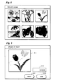
An example of the sample images having different
characteristics is the images having different tonalities.
According to the third invention, image display data
for displaying a plurality of sample images having different
characteristics is transmitted from the image server to the
image data receiver. When the image display data
transmitted from the image server is received by the image
data receiver, the plurality of sample images are displayed
on the display device of the image data receiver on the
basis of the received image display data. The user of the
image data receiver selects a sample image which is suited
the taste of the user from the displayed sample images. The
data representing the characteristics relating to the
selected sample image is transmitted to the image server.
In the image server, the data representing the
characteristics of the selected sample image is received, so
that image data can be adjusted so as to be image data
corresponding to the selected sample image. The adjusted
image data can be transmitted to the image data receiver.
Since the image data adjusted so as to suit the taste of the
user of the image data receiver can be transmitted to the
image data receiver, the adjusted image can be rapidly
displayed on the display device even if the image data
receiver cannot adjust an image.
Preferably, the image server transmits to the image
data receiver image data whose characteristics has not been
adjusted in a case where the image data receiver can change
or adjust the characteristics of the image displayed on the
displayed device. On the other hand, the image server
transmits to the image data receiver image data whose
characteristics has been adjusted in accordance with the
image characteristics data transmitted from the image data
receiver in a case where the image data receiver cannot
adjust or change the characteristics of the image displayed
on the display device.
The fourth invention is directed to a client computer
used in an image communication system in which an image
server having an image output device for outputting an image
and the client computer are capable of communicating with
each other, comprises image data quantity reduction device
(means) for reducing the data quantity of image data to be
transmitted to the image server such that the data quantity
of the image data to be transmitted is equal to or less than
the data quantity of the image data representing the image
to be outputted from the image output device, and image data
transmission device (means) for transmitting to the image
server the image data whose data quantity is reduced by the
image data quantity reduction device.
The fourth invention also provide a method suitable for
the client computer. The method of transmitting image data,
according to the fourth invention, from a client computer to
an image server, the client computer and the image server
being used in an image communication system in which the
image server having an image output device for outputting an
image and the client computer are capable of communicating
an image and the client computer are capable of
communicating with each other, comprises the steps of
reducing the data quantity of image data to be transmitted
to the image server such that the data quantity of the image
data to be transmitted is equal to or less than the data
quantity of the image data representing the image to be
outputted from the image output device, and transmitting to
the image server the image data whose data quantity is
reduced.
Furthermore, it also provides a recording medium having
a computer program recorded thereon for implementing the
fourth invention.
According to the fourth invention, when the image data
is transmitted from the client computer to the image server,
processing is performed such that the data quantity of the
image data to be transmitted is reduced. Since the data
quantity of the image data transmitted to the image server
is reduced, so that the time required for transmission is
shortened.
For example, the resolution of the image data
transmitted from the client computer is converted into a
resolution which is not more than the resolution of an image
which can be outputted from the output device (a display
device, a printer, etc.), thereby reducing the data quantity
of the image data.
Furthermore, the image data transmitted from the client
computer is thinned such that the size thereof is equal to
the size of the output image (print size, e.g.) to be
outputted from the output device, thereby reducing the
quantity of the image data.
The image data may be transmitted from the client
computer to the image server after being converted into
image data in a format having a high transmission efficiency
on the basis of the form of communication between the image
server and the client computer.
Since the image data is transmitted from the client
computer to the image server after being converted into the
image data having a high transmission efficiently, the
quantity of the image data is reduced, so that time required
to transmit the image data can be shortened. It is possible
to realize efficient transmission of the image data.
An image constituting a part of an image of one frame
may be extracted, to transmit image data representing the
extracted image from the client computer to the image
server. Since the data quantity of the image data
transmitted from the client computer to the image server is
reduced, time required for transmission is shortened.
A compression rate is determined on the basis of the
speed of transmission of the image data between the image
server and the client computer. Image data compressed at
the determined compression rate can be also transmitted from
the client computer to the image server. Since the image
data is compressed on the basis of the speed of transmission
of the image data, the quantity of the image data to be
transmitted is reduced, so that time required to transmit
the image data can be shortened.
The compression rate may be determined in response to a
compression command which is given.
The fifth invention is directed to a client computer
used in an image communication system in which an image
server and the client computer are capable of communicating
with each other, characterized by comprising compression
rate setting means (device) for setting the compression rate
of image data, calculation means (device) for calculating
information relating to time required for transmission in a
case where the image data compressed at the compression rate
set by the compression rate setting means is transmitted to
the image server, and a display device for displaying the
information relating to the time required for transmission
calculated by the calculation means.
The fifth invention also provides a method suitable for
implementation of the client computer. That is, it provides
a method of displaying information in a client computer
which is used in an image communication system in which an
image server and the client computer are capable of
communicating with each other, characterized by comprising
the steps of setting the compression rate of image data,
calculating information relating to time required for
transmission in a case where the image data compressed at
the set compression rate is transmitted to the image server,
and displaying the calculated information relating to the
time required for transmission.
Furthermore, it also provides a recording medium having
a computer program recorded thereon for implementing the
fifth invention.
According to the fifth invention, when the image data
is compressed, information relating to time required for
transmission in a case where the compressed image data is
transmitted from the client computer to the image server is
displayed. A user of the client computer can know the
information relating to the time required for transmission,
so that the compression rate can be further increased or
decreased, as required.
Preferably, an image represented by the image data
compressed at the compression rate is displayed. The user
can confirm the quality of the image represented by the
compressed image data with his or her eyes.
The sixth invention is directed to an image
communication system in which an image server and a client
computer are capable of communicating with each other,
characterized in that image data and information relating to
the image data are transmitted from the client computer to
the image server, the image server comprises an image output
device for outputting an image represented by the image data
on the basis of the information relating to the image data
transmitted from the client computer, and image information
transmission means (device) for transmitting to the client
computer the information relating to the image data
transmitted from the client computer, and the client
computer comprises retrieval means (device) for retrieving,
image data specified by the information relating to the
image data transmitted from the image server.
The sixth invention also provides a method of
communicating image. That is, in an image communication
system in which an image server and a client computer are
capable of communicating with each other, the method is
characterized by comprising the steps of transmitting image
data and information relating to the image data from the
client computer to the image server, outputting, in the
image server, an image represented by the image data on the
basis of the information relating to the image data
transmitted from the client computer, transmitting the
information relating to the image data transmitted from the
client computer, from the image server to the client
computer, and retrieving, in the client computer, image data
specified by the image information relating to the image
data transmitted from the image server.
Furthermore, it also provides a recording medium having
a computer program recorded thereon for implementing the
sixth invention.
According to the sixth invention, the information
relating to the image data transmitted to the image server
once is returned from the image server to the client
computer. The client computer retrieves the image data
which is the same as the image data transmitted to the image
server on the basis of the information relating to the image
data transmitted from the image data.
Since the image data transmitted to the image server
once can be retrieved in the client computer, image
synthesis processing, editing processing, and so forth can
be performed again using the image data.
The seventh invention is directed to a client computer
used in an image communication system in which an image
server having a printer and the client computer are capable
of communicating with each other, characterized by
comprising receiving means (device) for receiving a part of
printing template image data, which is transmitted from the
image server, used for printing processing in the printer,
and synthesis means (device) for synthesizing the part of
the printing template image data received by the receiving
means and a part of user image data stored in the client
computer.
The seventh invention also provides a method suitable
for the client computer. That is, it provides a method of
synthesizing images in a client computer which is used in an
image communication system in which an image server having a
printer and the client computer are capable of communicating
with each other, characterized by comprising the steps of
receiving a part of printing template image data, which is
transmitted from the image server, used for printing
processing in the printer, and synthesizing the received
part of the printing template image data and a part of user
image data stored in the client computer.
According to the seventh invention, the part of the
printing template image data used for the printing
processing is transmitted from the image server to the
client computer. A part of a composite image is generated
in the client computer using the part of the printing
template image data and the part of the user image data. A
user of the client computer can obtain the part of the
composite image to be printed, so that the user can confirm
the quality of the composite image to be actually printed
with his or her eyes.
An image editing system according to the eighth
invention is an image editing system in which an image
server and a plurality of client computers are capable of
communicating with one another, an image represented by
image data is edited in one of the client computers, and
editing information relating to the edited image is
transmitted from the one client computer to the image
server, wherein the image server comprises editing
information transmission means (device) for transmitting the
editing information relating to the edited image which has
been transmitted from the one client computer to the one
client computer or the other client computer, and the one or
other client computer comprises image reediting means
(device) for reediting the edited image generated in the one
client computer on the basis of the editing information
relating to the edited image which has been transmitted from
the image server, and reediting information transmission
means (device) for transmitting to the image server
reediting information relating to the reedited image
generated in the image reediting means.
The eighth invention also provides a method suitable
for the above-mentioned image editing system. That is, it
provides an image editing method, wherein an image server
and a plurality of client computers are capable of
communicating with one another, comprising the steps of
editing an image using an image represented by image data in
one of the client computers, transmitting editing
information relating to the edited image from the one client
computer to the image server, receiving the editing
information transmitted from the one client computer in the
image server, transmitting the received editing information
from the image server to the one client computer or other
client computer, reediting the edited image generated on the
basis of the editing information transmitted from the image
server in the one or other client computer, and transmitting
reediting information relating to the reedited image from
the one or other client computer to the image server.
According to the eighth invention, the image server and
the plurality of client computers are connected via a
network, for example, such that they are capable of
communicating with one another, as described above. The
image is edited in one of the plurality of client computers.
The information relating to the edited image, for example,
the edited image itself, the file names for specifying
images constituting the edited image so as to reproduce the
edited image, data representing the positions where the
images are arranged, and the like is transmitted to the
image server from the one client computer where the image
editing processing has been performed.
In the image editing system, the edited image generated
in the client computer can be reedited. The edited image
can be reedited by the one client computer which has edited
the image, or can be reedited by the client computer other
than the one client computer which has edited the image.
When the image is reedited, the information relating to
the edited image which has been transmitted from the one
client computer which has edited the image is transmitted
from the image server to the one or other client computer
which edits the image. In the client computer which has
received the editing information (information relating to
the edited image), the edited image is reproduced on the
basis the received editing information. The reproduced
edited image is subjected to reediting, for example,
addition, deletion or alteration (movement in position,
reduction, enlargement, etc.) of an image, a character or a
sign.
The reediting information relating to the image thus
reedited is transmitted to the image server from the client
computer which has reedited the image.
As described in the foregoing, the image edited in the
one client computer can be reedited in the one or other
client computer. The plurality of client computers can edit
one image in cooperation, so that a better image can be
generated.
Preferably, the editing information transmitted from
the client computer is stored in the image server. When the
image is reedited, information relating to a reedited
portion is transmitted from the client computer to the image
server. The reedited image can be reproduced from the
editing information stored in the image server and the
reediting information transmitted from the client computer.
The amount of the information relating to the reedited
portion is small. Since the amount of the information is
small, a time period required when the reediting information
is transmitted to the image server from the client computer
which has reedited the image may be relatively short.
In one embodiment, the plurality of client computers
are classified into a plurality of groups each comprising
one or two or more of the client computers. Execution data
indicating that an image is edited or reedited is
transmitted from the one or other client computer to the
image server prior to editing or reediting the image. It is
judged whether or not the editing or reediting of the image
is allowed on the basis of the execution data transmitted
from the one or other client computer. When it is judged
that the editing or reediting of the image is allowed, data
representing allowance is transmitted from the image server
to the one or other client computer which has been allowed
to edit or reedit the image. The one or other client
computer performs editing or reediting the image in response
to the receiving of the allowance data transmitted from the
image server.
The execution data indicating that the image is edited
or reedited is transmitted to the image server prior to
editing or reediting the image in the client computer, and
the image is edited or reedited only when the editing or
reediting of the image is allowed by the image server.
Therefore, the image is not simultaneously edited or
reedited in the plurality of client computers, thereby
preventing a lot of different edited images from existing
together.
Furthermore, in another embodiment, the plurality of
client computers are classified into a plurality of groups
each comprising one or two or more of the client computers.
The edited image is constituted by a plurality of object
images. Object image editing request data indicating that
the object images are subjected to object image editing
which includes at least one of addition, alteration and
deletion is transmitted from the one or other client
computer to the image server. The image server judges
whether or not the object image editing is allowed on the
basis of the object image editing request data transmitted
from the one or other client computer, and transmits, when
it is judged that the object image editing is allowed,
object image editing allowance data for allowing the object
image editing to the one or other client computer which has
been allowed to edit the object image. The one or other
client computer performs the object image editing in
response to the receiving of the object image editing
allowance data transmitted from the image server.
By obtaining the object image editing allowance data,
the object images constituting the edited image can be
edited in the respective client computers. In the different
client computers, it is possible to subject different object
images constituting the same edited image to object image
editing (addition, alteration (including change in the
position where the object image is arranged, or enlargement
or reduction of the object image), deletion, etc.).
Furthermore, when the client computers are classified
into the plurality of groups, the editing information or the
reediting information may be transmitted to the client
computer in the group to which the one or other client
computer which has transmitted the editing information
belongs.
The client computer in the group receives the editing
information or the reediting information, so that the edited
image or the reedited image can be reproduced. In the
client computers other than the client computer which has
edited or reedited the image, the edited image or the
reedited image can be confirmed.
Furthermore, it is preferable that the one or other
client computer further comprises comment entry means
(device) for entering a comment concerning the editing
information or the reediting information which has been
transmitted from the image server, and comment transmission
means (device) for transmitting to the image server the
comment entered from the comment entry means.
The comment concerning the edited image or the reedited
image can be added, so that the edited image can be reedited
on the basis of the comment. The edited image can be
further expanded.
The foregoing and other objects, features, aspects and
advantages of the present invention will be become more
apparent from the following detailed description of
exemplary embodiments of the present invention when
taken in conjunction with the accompanying drawings.
BRIEF DESCRIPTION OF THE DRAWINGS
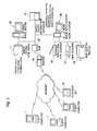
Fig. 1 illustrates the overall configuration of an
image communication system according to the first embodiment
of the present invention;
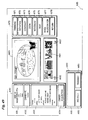
Fig. 2 illustrates a monitor information table stored
in an image/device information database;
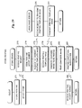
Fig. 3 is a flowchart showing the procedure for image
reading processing performed by an image input/output work
station;
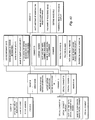
Figs. 4 to 7 are flowcharts showing the procedure for
transmission/receiving processing of image data which is
performed between a client computer and an image server;
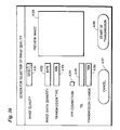
Figs. 8 and 9 illustrate examples of a display screen
of a monitor display device connected to a client computer;
Figs. 10 to 14 relate to the second embodiment of the
present invention;
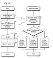
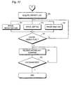
Fig. 10 is a flowchart illustrating the procedure for
processing for judging the taste for a tonality of an image
of a user of a client computer or a television set;
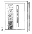
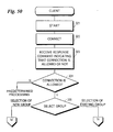
Fig. 11 illustrates one example of a display screen of
a monitor display device connected to a client computer or a
television set;
Fig. 12 is a flowchart showing the procedure for
transmission/receiving processing of data between a client
computer or a television set and an image server;
Fig. 13 is a flowchart showing the procedure for
transmission/receiving processing of image data between a
television set and an image server;
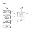
Fig. 14 is a flowchart showing the procedure for
transmission/receiving processing of image data between a
client computer and an image server;
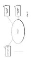
Fig. 15 illustrates the overall outline of an image
communication system according to the third embodiment;
Fig. 16 is a block diagram showing the electrical
configuration of a client computer.;
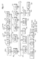
Fig. 17 is a block diagram showing the electrical
configuration of a main image server;
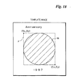
Fig. 18 illustrates one example of a template image;
Fig. 19 illustrates one example of an LIF;
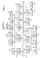
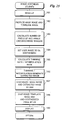
Fig. 20 is a flowchart showing the outline of the
procedure for image synthesis processing;
Fig. 21 shows a flowcharts of the procedure for
transmission processing of template image data and mask
image data which is performed between a client computer and
a main image server;
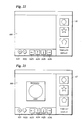
Figs. 22 and 23 illustrate examples of a display screen
of a display device in a client computer;
Fig. 24 is a flowchart showing reading processing of a
user image in a client computer;
Fig. 25 is a flowchart showing image synthesis
processing;
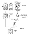
Fig. 26 illustrates image synthesis processing;
Fig. 27 is a flowchart showing a modified image
synthesis processing;
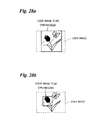
Figs. 28a and 28b illustrate modified examples of image
synthesis processing;
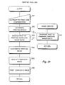
Fig. 29 shows flowcharts of the procedure for partial
printing processing;
Figs. 30a and 30b illustrate examples of a display
screen of a display device in a client computer ;
Fig. 31 is a flowchart showing conversion processing of
image data to be transmitted;
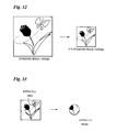
Fig. 32 illustrates a user image and an image
represented by image data to be transmitted;
Fig. 33 shows how a part of a user image is extracted;
Fig. 34 is a flowchart showing the procedure for image
quality selection processing;
Fig. 35 is a flowchart showing the procedure for
transmission capability calculation processing;
Fig. 36 illustrates one example of a display screen of
a display device in a client computer;
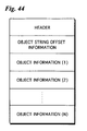
Fig. 37 illustrates a file format of image data to be
transmitted;
Fig. 38 shows flowcharts of the procedure for printing
processing of a composite image;
Fig. 39 shows flowcharts of the procedure for store
printing processing;
Fig. 40 shows flowcharts of the outline of the
procedure for resynthesis processing;
Fig. 41 is a flowchart showing the procedure for
specific resynthesis processing;
Fig. 42 shows the fourth embodiment of the present
invention and illustrates the configuration of an image
editing system;
Fig. 43 illustrates an example of the data structure of
a file stored in a system database;
Fig. 44 to 48 illustrate examples of editing
information;
Fig. 49 illustrates a GUI for edited image entry which
is displayed on a display screen of a client computer;
Figs. 50 to 52 are flowcharts showing the procedure for
image editing processing in a client computer;
Figs. 53 to 54 are flowcharts showing the procedure for
image editing processing in an editing server;
Fig. 55 is a flowchart illustrating owner flag
acquisition processing in a client computer;
Fig. 56 is a flowchart illustrating image registration
processing in a client computer;
Fig. 57 is a flowchart illustrating image editing
processing in a client computer;
Figs. 58a to 58f illustrate windows displayed on a
display screen of a client computer;
Fig. 59 is a flowchart showing owner flag cancel
processing in a client computer;
Fig. 60 is a flowchart showing comment
transmission/receiving processing in a client computer;
Fig. 61 is a flowchart showing special comment
transmission/receiving processing in a client computer;
Figs. 62 to 64 illustrate examples of a display screen
of a client computer;
Figs. 65 to 71 illustrate the fifth embodiment of the
present invention;
Fig. 65 illustrates an example of the data structure of
a file stored in a system database;
Fig. 66 illustrates one example of a display screen of
a client computer;
Fig. 67 is a flowchart showing the procedure for
processing performed by an editing server in a case where a
request for an edited image owner flag is issued by a client
computer;
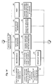
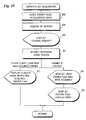
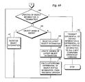
Figs. 68 and 69 are flowcharts showing the procedure
for processing performed by an image server in a case where
the whole of an edited image is edited;
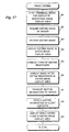
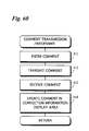
Fig. 70 is a flowchart showing the procedure for
processing performed by an image server in a case where a
request for an object image owner flag is issued by a client
computer;
Fig. 71 is a flowchart showing the procedure for
processing performed by an image server in a case where an
object image is edited.
DESCRIPTION OF THE PREFERRED EMBODIMENTS
(A) First Embodiment
Fig. 1 illustrates the overall configuration of an
image communication system according to a first embodiment
of the present invention.
In an image communication system, image data is
previously stored in an image saving disk array 11 connected
to an image server 10, described later, and the image data
is read out from the image saving disk array 11 in response
to a readout command from a client computer 1 and is
transmitted to the client computer 1.
In the image communication system, a lot of client
computers 1 can be connected to a router 14 via an internet.
In Fig. 1, a television set 1A which can be connected to the
internet is also illustrated.
The image server 10 is connected to the router 14
through a hub 13. The image saving disk array 11 and an
image/device information database 12 are connected to the
image server 10. Printing image data representing printing
images, editing image data representing editing images, and
thumbnail image data (reduced image data) representing
thumbnail images (reduced images) are stored, as described
later, in the image saving disk array 11. There are a
printing image, an editing image and a thumbnail image for
one image, and the printing image data, editing image data
and thumbnail image data respectively representing the above
images provided for one image are correlated with one
another with respect to the one image. The image/device
information database 12 stores longitudinal/transverse
information indicating which of longitudinal display and
transverse display of an image is correct, data representing
the location (image storage location) in the image saving
disk array 11 where each type of image data is saved (the
location is determined in correspondence with the file name
of the image), and monitor information as shown in Fig. 2 in
the form of a table, as described later.
An image input/output work station 15 is connected to
the router 14 via the hub 13. A reflection type scanner 16,
a film scanner 17 and a high-quality printer 18 are
connected to the image input/output work station 15. An
image on an original or a film is read by the reflection
type scanner 16 or the film scanner 17. Image data
representing the read image is saved upon being assigned a
file name as printing image data in the image saving disk
array 11 under control of the image server 10. The location
(image storage location) where the image data is stored in
the image saving disk array 11 is stored in correspondence
with the file name of the image data in the image/device
information database 12. Further, editing image data and
thumbnail image data are generated from the printing image
data when the printing image data is stored in the image
saving disk array 11, and are stored in the image saving
disk array 11 in relation to the printing image data under
respective unique file names, as described later.
Fig. 3 is a flow chart showing the procedure for image
read-in processing. The image read-in processing is
performed by the image input/output work station 15.
A user of the client computer 1 hands a film on which a
desired image (or images) is recorded to an operator of the
image input/output work station 15. The operator of the
image input/output work station 15 starts the film scanner
17 (step 21), and sets a film kept from the user of the
client computer 1 in the film scanner 17 (step 22).
An image (or images) designated by the user of the
client computer 1 is read out of images recorded on the film
set in the film scanner 17 (step 23). Image data
representing the read image is temporarily stored in a
memory contained in the image input/output work station 15
in relation to the file name. The longitudinal/transverse
information relating to the image data representing the
image read from the film scanner 17 is then entered by the
operator of the image input/output work station 15 (step
24). The longitudinal/transverse information is temporarily
stored in the memory contained in the image input/output
work station 15.
The image data stored in the memory contained in the
image input/output work station 15 is subjected to the color
space conversion processing (conversion from the RGB system
to XYZ system) (step 25). The color space conversion
processing will be described in detail later.
The image data, which has been subjected to the color
space conversion processing and which is represented by the
XYZ system, is stored, upon being related to the file name,
as printing image data, in an image storage location of the
image saving disk array 11 designated by the operator of the
image input/output work station 15 (step 26). Further, the
file name of the printing image data and the storage
location where the printing image data is saved are stored
in the image/device information database 12. Further
longitudinal/transverse information temporarily stored in
the memory of the image input/output work station 15 is
transferred to and stored in the image/device information
database 12.
Editing image data (the XYZ system) having a lower
resolution than the resolution of the printing image data
and thumbnail image data (the XYZ system) having a still
lower resolution than the resolution of the editing image
data are generated from the printing image data (image data
after conversion, represented by the XYZ system) by the
image input/output work station 15. The editing image data
and the thumbnail image data are then subjected to display
direction conversion processing such that they can be
displayed in a correct direction (step 27), and are stored
in the image saving disk array 11 in correspondence with the
printing image data (represented by the XYZ system) (step
28). Of course, the editing image data and thumbnail image
data both represented by the RGB system may be generated
based on the printing image data of the RGB system to be
stored. Specifically, the thumbnail image data preferably
is represented by the RGB system so that it is not necessary
to perform a color space conversion processing when the
thumbnail image data is transmitted to the client computer 1
from the image server 10. The storage locations where the
editing image data and the thumbnail image data are saved
are also stored in the image/device information database 12
in relation to the file name of the editing image data and
the file name of the reduced image data.
Brief description is made of the color space conversion
between the RGB space and the XYZ space.
Image data represented in the RGB space is converted to
image data represented in the XYZ space by the following
equation, and
vice versa.
Where Xy, Yr and Zr denote three stimulus values for the
primary (color) R, Xg, Yg and Zg, for the primary G, and Xb,
Yb and Zb, for the primary B.
The 3×3 matrix representing a conversion coefficient in
Eq. (1) is expressed using white points X
w, Y
w and Z
w as
follows;
where the relation Z
i=1-X
iY
i (i=w, r, g, b) holds.
In a case where image data represented by the XYZ
system is converted to image data represented by the RGB
system to be supplied to a display device, the coefficients
ar, ag and ab are calculated in accordance with the equation
(2) using the white points Xw and Yw (Zw is obtained from Xw
and Yw) and three stimulus values for primaries Xr, Yr (Zr is
obtained from, Xg and Yg) and Xb, Yb (Zb is obtained from Xb
and Yb) which conform to characteristics of the display
device. The conversion coefficient matrix in the equation
(1) is expressed by these stimulus values and the
coefficients ar, ag and ab. Accordingly, the image data of
RGB system which conforms to the characteristics of the
display device is obtained from the image data of XYZ system
in accordance with the equation (1) (the processing of step
72 in Fig. 6 described later).
There is a relationship expressed by an equation (3)
between an input voltage V and luminance I in a display
device.
I = KVγ
Consequently, in order to display an image on the
display device, the image data of the RGB system needs to be
subjected to reverse gamma (γ) correction. Generally, the
gamma characteristics varies in dependence upon types of
display devices.
Described in the monitor information table shown in
Fig. 2 are white points, three stimulus values for primaries
and y characteristics in correspondence (refereed to as
monitor information) to a plurality of types of monitor
display devices (inclusive of a standard type).
In a case where, on the basis of image data represented
by the XYZ system, an image represented by the image data is
printed by a printer (the high-quality printer 18), the
image data of the XYZ system (space) is also converted to
image data of the RGB system (space) or the three primaries
system (space) (e.g., Cyan, Yellow and Magenta). Since a
printer has generally non-liner characteristics, the image
data of the XYZ system is converted to the primaries system
(e.g., the RGB system) using a conversion table (for
example, three dimensional look up table (LUT)) (which are
previously stored in a memory of the image input/output work
station 15). Of course, first the image data of the XYZ
system is converted to the image data of the primaries (RGB)
system in accordance with the equations (1) and (2), and
then the image data of the primaries system is subjected to
non-linear conversion in dependence upon the printer
characteristics.
In this way, on one hand the image data of the XYZ
system is converted to the image data of the RGB system in
consideration of the characteristics of a monitor display
device to be used for display, and on the other hand the
image data of the XYZ system is converted to the image data
of the RGB (primaries) system in consideration of the
characteristics of a high-quality printer to be used for
printing, the image displayed on the display device and the
image obtained by printing in the printer match (coincide)
with each other in color.
The image data outputted from the film scanner 17 or
the reflection type scanner 16 is one which is represented
by the RGB system. White points and three stimulus values
which conform to characteristics of the scanner are stored
in the memory of the image input/output work station 15.
The image data of the RGB system is converted to the image
data of the XYZ system in accordance with the equations (1)
and (2) using the above white points and three stimulus
values. This is the color space conversion processing in
step 25 of Fig. 3 described above.
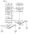
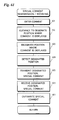
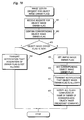
Figs. 4 to 7 are flow charts showing the procedure for
data transmission/receiving processing performed between the
client computer 1 and the image server 10. Figs. 8 and 9
illustrate examples of images displayed on a display screen
of the monitor display device in the client computer 1.
When the client computer 1 and the image server 10 are
connected to each other via an internet, data representing a
request to transmit thumbnail image data (inclusive of data
representing the file name) and data representing a TCP/IP
address for specifying the client computer 1 are transmitted
from the client computer 1 to the image server 10 (step 31).
When the image server 10 receives the data representing
the request to transmit reduced image data and the data
representing the TCP/IP address for specifying the client
computer 1 (step 51), the storage location where the
thumbnail image data is saved is read out of the
image/device information database 12 and the thumbnail image
data is searched in the image saving disk array 11 (step
52). When the thumbnail image data is found in the image
saving disk array 11 connected to the image server 10, the
found thumbnail image data is transmitted to the client
computer 1 specified by the TCP/IP address (step 53). When
no corresp.onding reduced image data is retrieved from the
image saving disk array 11, error data is transmitted to the
client computer 1 specified by the TCP/IP address.
The client computer 1 receives the thumbnail image data
transmitted from the image server 10 (step 32). A list of
thumbnail images represented by the received thumbnail image
data is displayed on the monitor display device connected to
the client computer 1, as shown in Fig. 8 (step 33).
The user of the client computer 1 moves a cursor onto
the image, which the user desires to print, out of the
plurality of thumbnail images which are displayed on the
monitor display device, and clicks. Consequently, the image
to be printed is selected. When the image to be printed is
selected, data representing the file name of the thumbnail
image of the image to be printed, data representing
information relating to the monitor display device connected
to the client computer 1 (data representing the type of the
monitor display device, data representing the resolution of
the monitor display device connected to the client computer
1 and the number of colors which can be displayed, these
data being stored in the client computer 1), and data
representing the TCP/IP address for specifying the client
computer 1 are transmitted from the client computer 1 to the
image server 10 (step 35).
The image server 10 receives the data representing the
file name of the selected thumbnail image, the data
representing the monitor display device information, and the
data representing the TCP/IP address which have been
transmitted from the client computer 1 (step 54).
The image server 10 retrieves editing image data
corresponding to the data representing the selected
thumbnail image from the image saving disk array 11 by
referring to the image/device information database 12 (step
55).
If the editing image data related to the selected
thumbnail image cannot be found in the image saving disk
array 11 (NO at step 56), error data is transmitted to the
client computer 1 specified by the received TCP/IP address
(step 57).
When the client computer 1 receives the error data
transmitted from the image server 10 (YES at step 36), an
error is displayed on the monitor display device connected
to the client computer 1, and it is reported to the user of
the client computer 1 that an error occurs (step 37). If
necessary, the user accesses the image server 10 again.
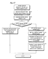
When the editing image data is found in the image
saving disk array 11 (YES at step 56), the monitor display
device information which has been transmitted from the
client computer 1 is analyzed (step 58).
The type and resolution of the monitor display device
of the client computer 1 and the number of colors which can
be displayed are recognized by the analysis of the monitor
display device information. The type, resolution and the
number of colors of the monitor display device are stored in
the memory contained in the image server 10 (step 59).
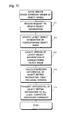
In a case where the number of colors of an image
represented by the editing image data is not less than the
number of colors which can be displayed on the monitor
display device of the client computer 1, all the colors of
the image represented by the editing image data cannot be
displayed on the monitor display device of the client
computer 1 even if the editing image data stored in the
image saving disk array 11 is transmitted as is to the
client computer 1. In such a case, even if the entire
editing image data stored in the image saving disk array 11
is transmitted as is to the client computer 11, it is a
waste of time for transmission. If the number of colors of
the image represented by the editing image data stored in
the image saving disk array 11 is not less than the number
of colors which can be displayed on the monitor display
device of the client computer 1 (YES at step 60), a color
reduction flag is set to "1" and the number of colors which
can be displayed on the monitor display device of the client
computer 1 is stored (step 61). The number of colors of the
image represented by the editing image data is decreased to
the number of colors which can be displayed on the monitor
display device connected to the client computer 1 as
described later (color reduction processing).
Furthermore, the monitor information table of the
image/device information database 12 is searched on the
basis of the display device information (the type of the
monitor display device) transmitted from the client computer
1, and it is judged whether or not the monitor information
relating to the corresponding monitor display device is
stored in the image/device information database 12 (step
62).
When the monitor information relating the type of the
monitor display device of the client computer 1 is stored in
the image/device information database 12 (the monitor
information table) (YES at step 62), the monitor information
is read out of the image/device information database 12, and
is temporarily stored in the memory contained in the image
server 10 (step 64). If the monitor information relating to
the corresponding monitor display device is not stored in
the image/device database 12 (NO at step 62), the monitor
information relating to the standard monitor display device
is read out of the monitor information table and is
temporarily stored in the memory contained in the image
server 10 (step 63).
Furthermore, a thinning rate for changing the
resolution of the editing image data to the resolution of
the image displayed on the monitor display device is
calculated (step 65).
The monitor display information temporarily stored in
the memory contained in the image server 10 is then read out
(step 66).
The editing image data stored in the image saving disk
array 11 and corresponding to the selected thumbnail image
is read out, and is temporarily stored in the image server
10 (step 67). The thinning processing of the read editing
image data is performed in the image server 10 such that the
resolution thereof becomes a resolution corresponding to or
equal to the resolution of the monitor display device
connected to the client computer (step 68). The data
quantity of the editing image data is reduced, so that the
editing image data can be rapidly transmitted.
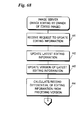
A check is then made to see whether or not the color
reduction flag is set (step 69). If the color reduction
flag is set (step 70), it is indicated that the number of
colors which can be displayed on the monitor display device
of the client computer 1 is less than the number of colors
of the image represented by the editing image data. Even if
the editing image data is transmitted as is to the client
computer 1, it is a waste of time for transmission, so that
color reduction processing of the editing image data is
performed (step 71). The color reduction processing will be
described in detail later. Unless the color reduction flag
is set, all the colors of the image represented by the
printing image data can be displayed as they are on the
monitor display device connected to the client computer 1,
so that the color reduction processing is skipped. Since
the color reduction processing is performed depending on the
number of colors which can be displayed on the monitor
display device, the data quantity of the editing image data
is reduced, so that it is feasible to rapidly transmit the
editing image data.
Color space conversion processing is then performed
such that a color of the image displayed on the monitor
display device connected to the client computer 1 coincides
with a color of the image which would be printed in the
high-quality printer 18 (step 72). The color space
conversion processing is that described above. Of the
monitor information (white points, three stimulus values and
gamma characteristics) which has been stored in the memory
of the image server 10 at step 64 or step 63, the data
relating to the white points and three stimulus values are
used to convert the image data in the XYZ space to the image
data in the RGB space in accordance with the equations (1)
and (2). The color space conversion processing is effective
in a case where the editing image data is represented by the
XYZ system. The editing image data of the RGB system is
further subjected to the reverse gamma correction using the
gamma characteristics.
The editing image data which has been subjected to the
color space conversion processing, the color reduction
processing as required and gamma correction is transmitted
from the image server 10 to the client computer 1 specified
by the TCP/IP address (step 73).
The editing image data transmitted from the image
server 10 is received by the client computer 1 (step 38).
When the editing image data is received by the client
computer 1, an editing image represented by the received
editing image data is displayed on a printing order screen
of the monitor display device connected to the client
computer 1, as shown in Fig. 9 (step 39). An area All where
an editing image is displayed, an area A13 where the number
of prints of an image to be printed corresponding to the
editing image which is displayed on the area All, an area
A12 clicked by the user when a printing command is entered,
and an area A14 clicked when printing order operation is
terminated are displayed on the printing order screen shown
in Fig. 9. Since the editing image has been already
subjected to longitudinal/transverse conversion in the image
reading processing shown in Fig. 3 such that the direction
of display is correct, the editing image is displayed
correctly without longitudinal/transverse operation
performed by the user of the client computer 1.
The user of the client computer 1 confirms the editing
image which is displayed on the monitor display device of
the client computer 1, and clicks the area A12 when a high-quality
image corresponding to the editing image is to be
printed. The user of the client computer 1 then enters the
number of prints from a keyboard of the client computer 1.
The entered number of prints is displayed on the area A13.
When the user of the client computer 1 clicks the area A14,
printing instruction operation is terminated (step 40).
Data representing the file name of the editing image
corresponding to the image to be printed, data representing
the TCP/IP address for specifying the client computer 1, and
data representing the number of prints are transmitted from
the client computer 1 to the image server 10 as data
representing an image printing instruction (step 41).
When the data representing the image printing
instruction is received by the image server (step 74),
printing image data is retrieved out of the image saving
disk array 11 on the basis of the data representing the file
name of the editing image data included in the data
representing the image printing instruction (step 75).
Longitudinal/transverse information relating to the found
printing image data is read out of the image/device
information database 12, and the printing image data is
subjected to longitudinal/transverse conversion such that
the printing image represented by the printing image data is
correctly printed on printing paper which is set in the
high-quality printer 18 (step 76).
The printing image data is transmitted from the image
server 10 to the image input/output work station 15, and a
high-quality image which is represented by the printing
image data is printed by the high-quality printer 18 under
control of the image input/output work station 15 (step 77).
Since the printing image data is represented by the XYZ
system, the color space conversion from the XYZ space to the
RGB space conforming to the characteristics of the high-quality
printer 18 is performed in the image server 10, the
image input/output work station 15 or the high-quality
printer 18 as described above, and the printing is made by
the high-quality printer 18 using the printing image data
which has been converted to the RGB system. When the image
printing of the instructed number of prints is completed by
the high-quality printer 18, a message indicating that
printing is terminated is transmitted from the image
input/output work station 15 to the image server 10. As a
result, the message indicating that printing is terminated
is transmitted from the image server 10 to the client
computer 1 (step 78).
When the client computer 1 receives the message, which
has been transmitted from the image server 10, indicating
that printing is terminated (step 42), the message
indicating that printing is terminated is displayed on the
monitor display device connected thereto (step 43). When
there is still another to be printed, the processing at the
step 34 and the subsequent steps is repeated again (step
44).
The color reduction processing (processing for reducing
the number of colors) performed in the image server 10 (the
processing at step 71) will be described.
Assume that the image represented by the editing image
data stored in the image saving disk array 11 is in full
color (the number of colors is approximately 16,000,000),
and the maximum number of colors which can be displayed on
the monitor display device connected to the client computer
1 is 256 will be described.
There are 256 colors (tones or levels) for each primary
(color) in full color so that the number of the all
combinations of the three primaries is about 16,000,000 (256
× 256 × 256). A color reduction table (pallet) describes
256 colors in the monitor display device and combinations of
colors (tone or levels) of three primaries in full color
(limited to 256 combinations) in correlation therebetween.
If one color in the full color is given, one combination
which is the closest to the given color is selected among
the combinations of the colors of three primaries described
in the color reduction table. A color of the monitor
display device which is correlated with the selected
combinations of colors of three primaries is read out of the
color reduction table. This is the color reduction
processing from the full color to 256 colors of the monitor
display device using the color reduction table.
In a case where the color reduction processing (the
processing at step 71) is performed, image data obtained by
the color reduction processing (image data in 256 colors,
for example) is subjected to the color space conversion
processing (the processing at step 72). In a case where the
color reduction processing is not performed, image data
which is not subjected to the color reduction processing
(image data in full color, for example) is subjected to the
color space conversion processing.
Although in the above-described embodiment, the
processing for reducing the resolution of the editing image
data and the color reduction processing are performed in
accordance with the information relating to the monitor
display device transmitted from the client computer 1, the
processing for reducing the resolution and the color
reduction processing may be performed in response to an
instruction inputted by the user of the client computer 1.
(B) Second Embodiment
Figs. 10 to 14 illustrate a second embodiment. In the
second embodiment, communication of image data is
established between an image server 10 and a client computer
1 or the television set 1A which can be connected to an
internet (see Fig. 1). A user selects a tonality (a color
tone) off an image which suits the taste of the user and the
image having the selected tonality is displayed on the
monitor display device of the client computer 1 or the
television set 1A which can be connected to an internet.
When the tonality adjustment or tonality changing is
performed in the television set 1A, which can be connected
to the internet, containing a CPU with a low processing
speed, it takes long time to perform the tonality adjusting
or changing processing, so that time required until an image
is displayed is lengthened. In the present embodiment,
therefore, it is judged whether a device requiring image
data of the image server 10 is a device having a CPU capable
of performing high-speed processing, for example, the client
computer 1 or a device having a CPU performing low-speed
processing, for example, the television set 1A.
In the case of the device having a CPU capable of
performing high-speed processing, for example, the client
computer 1, the client computer 1 performs the adjusting
processing. In the case of the device which performs low-speed
processing, for example, the television set 1A, the
image server 10 performs the tonality adjusting processing.
Even when image data is transmitted from the image server 10
to the device having a CPU with a low processing speed, for
example, the television set 1A, therefore, an image can be
rapidly displayed.
Fig. 10 is a flow chart showing the procedure for
processing of causing a user of the client computer 1 or the
television set 1A to select an image having a tonality (a
color tone) suiting the taste of the user. Fig. 11
illustrates one example of a display screen displayed on the
monitor display device connected to the client computer 1 or
the television set 1A.
The client computer 1 or the television set 1A is first
connected to the internet, so that the user accesses the
image server 10 (step 81).
A plurality items of image data which represent the
same sample image and respectively have different tonalities
are stored in an image/device information database 12
connected to the image server 10. When the client computer
1 or the television set 1A accesses the image server 10, the
plurality items of image data which differ in tonalities are
read out of the image/device information database 12 in
response to the access. The image data read out are
transmitted to the client computer 1 or the television set
1A which has accessed the image server 10 (step 91).
When the image data are received in the client computer
1 or the television set 1A, a plurality of sample images A,
B and C (referred to as display condition confirmation
images) which are represented by the received image data and
respectively have different tonalities are displayed on the
monitor display device connected to the client computer 1 or
the television set 1A (step 82). One example of a display
screen displayed at this time is illustrated in Fig. 11.
The tonality of the image A is the highest or strongest, the
tonality of the image B is medium, and the tonality of the
image C is the lowest or weakest. The user sees the
plurality of sample images displayed on the screen, to judge
which of the sample images suits the taste of the user
himself or herself, and select the sample image suiting the
taste of the user (step 83). If it is the client computer 1
that has accessed the image server 10, the sample image
suiting the taste out of the plurality of sample images
displayed on the monitor display device will be selected by
being clicked. If it is the television set 1A that has
accessed the image server, the sample image suiting the
taste will be selected by a remote controller attached to
the television set 1A.
Data representing the results thus selected is
transmitted to the image server 10 from the client computer
1 or the television set 1A (step 84).
The data representing the results of image selection
which have been transmitted from the client computer 1 or
the television set 1A is received by the image server 10. A
method of processing which would be performed on image data
when an image is displayed on the monitor display device of
the client computer 1 or the television set 1A is determined
on the basis of the data representing the selected results
which has been received (step 92). For example, when the
user of the client computer 1 or the television set 1A
selects the sample image A whose tonality is high, data
indicating that the taste of the user is an image whose
tonality is high (step 93). When the user selects the
sample image B whose tonality is medium, data indicating
that the taste of the user is an image whose tonality is
medium (step 94). Further, when the user selects the sample
image C whose tonality is low, data indicating that the
taste of the user is an image whose tonality is low (step
95).
Figs. 12 to 14 are flow charts showing the procedure
for processing in a case where a request to transmit image
data is issued from the client computer 1 or the television
set 1A after the taste for a tonality of the user has been
stored in the image server 10. If it is the client computer
1 that has issued the request to the image server 10, image
processing for changing the tonality into a tonality suiting
the taste of the user of the client computer is performed in
the client computer 1. On the other hand, if it is the
television set 1A that has issued the request to the image
server 10, image processing for changing the tonality into a
tonality suiting the taste of the user of the television set
1A is performed in the image server 10.
The client computer 1 or the television set 1A first
accesses the image server 10 (step 101).
When the image server 10 is accessed by the client
computer 1 or the television set 1A, image data representing
a device confirmation image is read out of the image/device
information database 12. The device confirmation image is
an image which make the user select one of the client
computer 1 and the television set 1A (i.e., one of the
device having a CPU with high processing speed and the
device having a CPU with low processing speed. The image
data representing the device confirmation image is
transmitted to the client computer 1 or the television set
1A which has accessed the image server 10 (step 121).
When the image data representing the device
confirmation image transmitted from the image server 10 is
received in the client computer 1 or the television set 1A,
the device confirmation image represented by the received
image data is displayed on the monitor display device
connected to the client computer 1 or the television set 1A
(step 102). The user judges to select which of the client
computer 1 and the television set 1A has accessed the image
server 10 in accordance with the guidance appearing on the
device confirmation image (step 103). Data representing the
selected results is transmitted to the image server 10 from
the client computer 1 or the television set 1A (step 104).
If it is the television set 1A that has been selected
by the user (step 105), and when a request to transmit image
data is issued to the image server 10 from the television
set 1A (step 106), the image server 10 performs the
processing of changing or adjusting the tonality of the
image data which is to be transmitted to the television set
1A such that the image suits the taste of the user of the
television set 1A (step 123). The tonality adjusting
processing is a processing in which levels or tones of the
R, G and B data constituting the image data are changed or
adjusted while the ratios among the R, G and B data are kept
constant. Image data which has been subjected to the
tonality adjusting processing in the image server 10 is
transmitted from the image server 10 to the television set
1A which has issued a request to transmit image data (step
124).
When the image data which has been already subjected to
the tonality adjusting processing is received in the
television set 1A, an image represented by the image data is
displayed on the television set 1A (step 107). The image
data is not subjected to tonality adjusting processing in
the television set 1A which includes a CPU with low
processing speed, so that the image can be rapidly
displayed.
In a case where it is the client computer 1 that has
accessed the image server 10 (step 105), when a request to
transmit image data is issued to the image server 10 from
the client computer 1 (step 108), the image data which has
been requested is retrieved in the image server 10, and the
retrieved image data and data representing a tonality
suiting the taste of the user who has requested transmission
of image data is transmitted to the client computer (steps
122 and 125).
In the client computer 1, the image data transmitted
from the image server 10 is subjected to tonality processing
on the basis of the data representing the tonality suiting
the taste of the user (step 109). An image obtained by the
tonality processing in the client computer 1 is displayed on
the monitor display device connected to the client computer
1 (step 110).
Although description was made of a case where the
processing performed in the image server or the client
computer 1 is tonality adjusting processing, the processing
is not limited to the tonality adjusting processing. For
example, it is possible to perform desired image processing
such as γ correction processing, contrast correction
processing, saturation emphasis processing, edge emphasis
processing or alteration of the size of a displayed image in
the image server or the client computer.
(C) Third Embodiment
(1) Configuration of image communication system
Fig. 15 illustrates the overall configuration of an
image communication system according to a third embodiment
of the present invention.
In the image communication system, a plurality of
client computers 40 (only one client computer is illustrated
in Fig.15), a main image server 30, and a store image server
31 are connected so as to be capable of communicating with
one another via an internet. The store image server 31 is
generally disposed in a laboratory.
In the image communication system, template image data
representing a template image (editing template image data
and printing template image data having a higher resolution
than that of the editing template image data) is stored in
the main image server 30. User image data representing a
user image or user images is stored in the client computer
40. The editing template image data is transmitted from the
main image server 30 to the client computer 40. In the
client computer 40, the user image represented by the user
image data is synthesized on the template image represented
by the transmitted editing template image data. When the
synthesis processing is thus performed, the user image data
and synthesis information for performing the synthesis
processing are transmitted from the client computer 40 to
the main image server 30. A composite image is printed in
accordance with synthesized image data created on the basis
of the synthesis information using the printing template
image data and the user image data in the main image server
30, and the printed composite image is delivered to a user
of the client computer 40. The composite image is also
printed in the store image server 31, as required. The
details will become clear in the following description.
Fig. 16 is a block diagram showing the electrical
configuration of the client computer 40. The client
computer 40 is usually located in the user's home.
The overall operation of the client computer 40 is
supervised by a CPU 72.
The client computer 40 comprises a ROM 73, a RAM 74 for
temporarily storing data, a VRAM (video RAM) 82 for storing
image data (synthesized image data) representing an image
displayed on a display device 84, and a memory controller 85
for controlling readout of data from the ROM 73 as well as
writing and reading of data to and from the RAM 74 and the
VRAM 82. The image data read out of the VRAM 82 is fed to a
digital-to-analog (DA) converter 83, whereby the image data
is converted into an analog video signal so that an image is
displayed on the display device 84.
A bus controller 75, a memory controller 85, and a
timer 86 are connected to the client computer 40.
Furthermore, a system I/O controller 76 is connected to
the client computer 40. Connected to the system I/O
controller 76 are a keyboard 77 and a mouse 78 for accepting
operation commands from the user of the client computer 40,
a CD-ROM drive 79 for reading the image data from a CD-ROM,
an FD drive 80, and a modem 81 for making connection to the
internet.
An external I/O controller 88 is connected to the
client computer 40. A flatbed scanner 91, a film scanner
92, a digital still-video camera 93, and a HD (hard disk)
drive 94 are connected to the external I/O controller 88.
An execution program is read out of a hard disk (not shown)
to and from which data can be written and read by the HD
drive 94 (this execution program is installed in the client
computer 40 and stored in the hard disk by loading a CD-ROM
storing the program into the CD-ROM drive 79, and reading
the program from the CD-ROM). Predetermined processing,
described later, is performed by the client computer 40 upon
reading out the execution program stored in the hard disk.
Data representing a list of editing template images stored
in the main image server is also stored in the hard disk.
Furthermore, a printer 90 for printing images and a
printer control circuit 89 for controlling the printer 90
are further connected to the client computer 40.
The user uses the client computer 40, to synthesize the
user image on the template image. The image synthesis
processing will be described in detail later.
Fig. 17 is a block diagram illustrating the electrical
configuration of the main image server 30. In Fig. 17, the
same components as those shown in Fig. 16 are assigned the
same reference numerals and hence, the description thereof
is not repeated. The store image server 31 has the same
structure as that of the main image server 30. The
execution program is installed in the main image server 30
(the store image server 31) and stored in the hard disk by
loading a CD-ROM storing the program into the CD-ROM drive
79 and reading the program from the CD-ROM.
A high-speed film scanner 95 is connected to the
external I/O controller 88 included in the main image server
30. Further, editing template image data representing an
editing template image, editing mask image data representing
an editing mask image, printing template image data
representing a printing template image, printing mask image
data representing a printing mask image, and an LIF (Layout
Image File) are stored in the hard disk, to and from which
data is written and read by the HD drive 94 which is
connected to the external I/O controller 88.
A high-quality printer 90A capable of doing high-quality
printing is connected to the main image server 30.
Fig. 18 illustrates one example of the template image.
A window W to which the user image is to be affixed is
formed in the template image. Window area data Sx, Sy, Ex and
Ey representing a rectangle F circumscribing the window W are
defined in order to stipulate the position of the window W
on the template image. The window area data Sx and Sy
represent the coordinates at the upper left corner of the
rectangle F circumscribing the window W, and the window area
data Ex and Ey represent the coordinates at the lower right
corner of the rectangle F circumscribing the window W.
The LIF includes addresses representing locations of
the editing template image data, the editing mask image
data, the printing template image data and the printing mask
image data, the window area data Sx, Sy, Ex and Ey, and an
aspect ratio of the template image (asp = the width of the
template image / the length of the template image), as shown
in Fig. 19. The LIFs are provided for each of template
images. The editing template image data, the editing mask
image data, the printing template image data and the
printing mask image data can be read out of the hard disk by
specifying the LIF.
(2) Outline of processing in image communication system
Fig. 20 is a flow chart showing the outline of image
synthesis processing performed in the image communication
system.
The client computer 40 is first started by the user of
the client computer 40 (step 131). The client computer 40
and the main image server 30 are connected to each other in
accordance with an address of the main server 30 which is
inputted or has been inputted into the client computer 40
(step 132).
When the client computer 40 and the main image server
30 are connected to each other, editing template image data
representing an editing template image is read out of the
hard disk in the main image server 30, and is transmitted
from the main image server 30 to the client computer 40
(step 133).
Image data representing an image desired by the user (a
user image) out of image data representing a plurality of
images stored in the hard disk in the client computer 40 is
read out of the hard disk, and is expanded on the VRAM 82 in
the client computer 40 (step 134).
The editing template image represented by the editing
template image data transmitted from the image server 30 and
user image are synthesized in the client computer 40, so
that a composite image is generated (step 135).
When composite image data representing the composite
image thus generated is saved in the client computer 40 (YES
at step 136), the composite image data is stored in the hard
disk by the HD drive 94 (step 137).
The composite image is printed in the image server 30.
A part of the composite image can be printed using the
printer 90 in the client computer 40 (partial printing)
(steps 138 and 139).
When the composite image is generated in the client
computer 40, user image and synthesis information
(information relating to an image to be transmitted) are
transmitted from the client computer 40 to the image server
30 in order to print the composite image in the image server
30. Upon this transmission processing, conversion (thin-out
or reducing) processing, described later, is performed such
that the quantity of image data representing the user image
is reduced (step 140). Since the quantity of the image data
is reduced, time required to transmit the image data is
shortened. Further, image quality selection processing,
described later, is performed.
The composite image can be printed in the main image
server 30, and can be also printed in the store image server
31 (printing in the store image server is refereed to as
store printing) (step 141). In the case of the store
printing, the image data representing the user image and the
synthesis information are transmitted to the store image
server 31 (step 143). When the store printing is not done,
the user image and the synthesis information are transmitted
to the main image server 30 (step 142).
The details of the image synthesis processing in the
image communication system will become clear in the
following description.
(3) Transmission processing of editing template image data
from main image server to client computer
Fig. 21 is a flow chart showing the procedure for
transmission processing of editing template image data from
the main image server 30 to the client computer 40 (the
processing in the step 133 shown in Fig. 20). Figs. 22 and
23 illustrate examples of screens on the display device 84
in the client computer 40.
Data representing a reduced template images is first
read out of the hard disk in the client computer 40, and a
list of reduced template images is displayed on the display
device 84, as shown in Fig. 22 (step 161).
A composite image display area AM where a composite
image is displayed and a reduced template image list display
area AT where a list of reduced template images is displayed
appear on the display screen of the display device 84, as
shown in Fig. 22. Further, an enlargement designating area
A21 clicked by a user when a user image to be synthesized is
enlarged, a reduction designating area A22 clicked by the
user when the user image to be synthesized is reduced, and
image position adjusting areas A23, A24, A25, and A26 for
adjusting the position of the user image to be synthesized
are further displayed on the display screen. The user image
to be synthesized is moved leftward by clicking the area
A23, the user image to be synthesized is moved upward by
clicking the area A24, the user image to be synthesized is
moved downward by clicking the area A25, and the user image
to be synthesized is moved rightward by clicking the area
A26.
The desired reduced template image out of the reduced
template images displayed in the area AT is clicked by the
user, so that the template image is selected (step 162).
When the template image is selected by the user, data
representing the LIF name corresponding to the selected
template image is transmitted from the client computer 40 to
the maim image server 30 (step 163).
The data representing the LIF name which has been
transmitted from the client computer 40 is received by the
main image server 30 (step 168).
When the data representing the LIF name is received by
the main image server 30, an LIF represented by the received
LIF data is retrieved. When the corresponding LIF is
retrieved from the hard disk, editing template image data
and editing mask image data, together with the LIF, are
transmitted from the main image server 30 to the client
computer 40 (step 169).
The LIF, the editing template image data and the
editing mask image data which have been transmitted from the
main image server 30 are received by the client computer 40
(step 164). The LIF, the editing template image data and
the editing mask image data which have been received are
temporarily written into the hard disk by the HD drive 94
(step 165).
The editing template image data and the editing mask
image data which have been temporarily written into the hard
disk are read out of the hard disk, and are expanded to a
bit map on the VRAM 82 (step 166). Consequently, the
editing template image is displayed, as shown in Fig. 23, on
the display screen of the display device 84 in the client
computer 40 (step 167).
(4) Read-out processing of user image in client computer 40
Fig. 24 shows the procedure for read-out processing of
a user image in the client computer 40 (the processing in
the step 134 shown in Fig. 20).
The user of the client computer 40 selects a user image
to be synthesized on a template image by designating its
file name (step 171).
Image data representing the user image which has been
designated by the user is read out of the hard disk (step
172). If the image data which has been read out is image
data in a format which is not supported in the client
computer 40 (NO at step 173), an error is displayed on the
display device 84 (step 174).
If the image data representing the user image which has
been designated by the user is supported in the client
computer 40 (YES at step 173), it is expanded to a bit map
file (steps 175 and 176). When it is the image data that
has already been expanded to the bit map file, the
processing in the step 176 is skipped.
When the user image data which has been expanded (or
developed) to the bit map file is obtained, the size and the
respective numbers of pixels in the longitudinal direction
and the transverse direction of the user image are
temporarily stored (steps 177 and 178). Thereafter, the
user image data is stored in the VRAM 82 (step 179), so that
the user image is displayed in the composite image display
area AM of the displayed screen of the display device 84.
The user image is displayed on the display device 84 with
the template image superimposed on the user image.
The user image data representing the user image to be
synthesized on the template image is thus obtained.
(5) Image synthesis processing
Fig. 25 is a flow chart showing the procedure for image
synthesis processing (the processing in the step 135 shown
in Fig. 20). Fig. 26 illustrates, in a case where image
synthesis is made using a template image, a mask image and a
user image, the process of the image synthesis in order to
make it easy to understand the image synthesis processing.
The image synthesis processing is performed in the
client computer 40. In the image synthesis processing, an
LIF stored in the hard disk is first read out (step 81).
An editing template image and an editing mask image are
then generated from editing template image data and editing
mask image data which are stored in the hard disk (step
182).
Window area data on the editing template image are read
out of the LIF, and the respective numbers of pixels in the
longitudinal direction and the transverse direction which
constitute a rectangle F circumscribing a window W are
calculated (step 183).
An image portion of the user image to be synthesized on
the template image (referred to as a user image to be
synthesized) in the image synthesis processing is then
specified by the user of the client computer 40 (step 84).
A pixel thinning rate or a pixel interpolation rate is
calculated (step 185) such that the size of the specified
user image to be synthesized and the size of the rectangle
circumscribing the window W coincide with each other. Pixel
thinning (image reducing processing) is performed using the
calculated thinning rate or pixel interpolation (image
enlarging processing) is performed using the calculated
interpolation rate (step 186) (the image obtained by this
processing is referred to as an extracted image).
The thinned or interpolated user image to be
synthesized is synthesized with the mask image such that a
part of the user image is mask by the mask image (referred
to as AND synthesis) (step 187).
The AND-synthesized image and the template image are
synthesized (referred to as OR synthesis) such that the
template image is laid on the mask portion of the mask image
(step 188). The synthesis processing ends with the OR
synthesis, so that a composite image in which an image
constituting a part of the user image appears in the window
W of the template image desired by the user is obtained.
The composite image thus obtained is displayed on the
display device 84 in the client computer 40.
Figs. 27 and 28 show another image synthesis
processing. Fig. 27 is a flow chart showing the procedure
for the image synthesis processing, which corresponds to a
part of the processing shown in Fig. 25. Fig. 28 shows how
images are synthesized in the image synthesis processing.
In this image synthesis processing, enlargement
processing of a user image to be synthesized is performed in
accordance with an enlargement rate which is set by the
user. When image enlargement is made (YES at step 191), an
image portion the size of which is equal to the size of the
rectangle F circumscribing the window W of the editing
template image is cut in accordance with the user's
designation out of the user image which has been enlarged
depending on the enlargement rate designated by the user
(steps 192, 193). The cut-out image serves as the user
image to be synthesized (see Fig. 28b and compare with Fig.
28a which shows the user image to be synthesized proceed in
the image synthesis processing shown in Figs. 25 and 26).
When the enlargement processing of the image is
performed, the quality of the image is lowered. An image
quality permissible range in which the image quality can be
satisfied even when it is lowered is previously set. When
the image quality is outside the image quality permissible
range in a case where the image enlargement processing is
performed (YES at step 194), the user is informed that the
image quality is lowered when the composite image is printed
by displaying the fact on the display device 84 (step 195).
The user may cancel the image enlargement processing, as
required.
(6) Partial printing processing
Although a composite image is printed by the main image
server 30 or the store image server 31, a part of the
composite image can be also printed in the printer 90 in the
client computer 40 in order to confirm the resolution of the
image to be printed. Such processing for checking a part of
a image to be printed is partial printing processing (the
processing in the step 139 shown in Fig. 20).
Fig. 29 is a flow chart showing the procedure for the
partial printing processing. Figs. 30a and 30b illustrate
examples of a screen on the display device 84 in the client
computer 40.
When the composite image is generated as described
above, the composite image is displayed on a composite image
display area AM on the display screen of the display device
84 in the client computer 40, as shown in Fig. 30a. Areas
A41 and A42 are displayed on the screen of the display
device 84 on which the composite image is displayed. The
area A41 is an area clicked by a user when a part of the
composite image to be printed is printed in order to confirm
the resolution of the composite image using the printer 90
in the client computer 40. The area A42 is an area clicked
by the user when store printing is done as described later.
When the area A41 is clicked by the user in a case
where the display screen of the display device 84 in the
client computer 40 is in a state as shown in Fig. 30a, it is
considered that an instruction to print a part of the
composite image is issued (step 201), and the printing range
of a part, to be printed, of the composite image is
determined (step 202). This determination is automatically
made such that the boundary between a template image and a
user image (an edge portion of a window W in the template
image) is included, that is, the range of the composite
image which is subjected to the partial printing processing
is predetermined in both the template image and the user
image. A part, to be printed, of the composite image may be
able to be designated by the user.
When a part, to be printed, of the composite image is
thus determined, part designation data indicating that a
part is determined and an LIF are transmitted from the
client computer 40 to the main image server 30 (step 202).
When the part designation data and the LIF which are
transmitted from the client computer 40 are received in the
main image server 30, a part of printing template image data
corresponding to the part (this part is predetermined as
described above), to be printed, of the composite image
while referring to the LIF is read out from the hard disk.
When the part of printing template image data is read out,
the part of the template image data is transmitted from the
main image server 30 to the client computer 40 (step 207).
The part of the printing template image data which has
been transmitted from the main image server 30 is received
in the client computer 40 (step 203).
A printing template image which is represented by the
part of the printing template image data and the user image
in the determined printing range are synthesized, thereby
generating a partial composite image (step 204). The
generated partial composite image is displayed on the
composite image display area AM on the screen of the display
device 84 (step 205), and is printed by the printer 90 (step
206). The user himself or herself of the client computer 40
can thus check a part of the composite image to be actually
printed, and can confirm the resolution of the composite
image to be printed in the main image server 30 or the store
image server 31.
(7) Conversion processing of image data to be transmitted
Fig. 31 is a flow chart showing the procedure for
conversion processing of image data to be transmitted (the
processing in the step 140 shown in Fig. 20). Figs. 32 and
33 illustrate an image represented by image data obtained by
the conversion processing of the image data to be
transmitted.
The conversion processing of image data to be
transmitted is performed in the client computer 40.
When the composite image is generated as described
above, an area A44 shown in Fig. 30b is clicked by a user,
so that an instruction to print the composite image is
issued (step 209).
The resolution of the high-quality printer 90A of the
main image server 30 has been stored in the hard disk of the
client computer 40. The resolution of the high-quality
printer 90A is read out of the hard disk of the client
computer 40 (step 211). The resolution of the high-quality
printer 90A and the resolution of user image used in the
composite image are compared with each other (step 212). If
the resolution of the high-quality printer 90A is lower than
the resolution of the user image, the data quantity of the
image data can be reduced by making the resolution of the
user image used in the composite image equal to the
resolution of the high-quality printer 90A. Therefore,
image data conversion processing is performed such that the
resolution of the user image used in the composite image is
equal to the resolution of the high-quality printer 90A
(step 213). For example, when the resolution of the user
image is 1800 dpi, and the resolution of the high-quality
printer 90A is 1200dpi, the image data thinning (conversion)
processing is performed such that the resolution of the user
image is 1200 dpi. If the resolution of the high-quality
printer 90A is higher than the resolution of the user image,
the processing in the step 213 is skipped.
The print size of a composite image is then designated
by the user (step 214). When the print size designated by
the user (for example, the size which is one-fourth the
standard print size) is smaller than the print size which is
predetermined in the main image server 30 (the standard
print size), image data thinning (conversion) processing is
performed such that printing into the print size which is
equal to the image size designated by the user can be
realized (step 216). Since the print size is reduced, the
data quantity of the image data to be transmitted from the
client computer 40 to the main image server 30 is reduced.
Image data representing a part of the image (referred
to as an extracted image) required to print the composite
image is extracted from the image data representing the user
image, as shown in Fig. 19 (step 220). Consequently, the
quantity of the image data transmitted from the client
computer 40 to the main image server 30 is reduced. The
extraction processing will be performed in correspondence
with the image extraction processing in the image synthesis
processing shown in Figs. 25 and 26.
The image data to be transmitted from the client
computer 40 to the main image server 30 is thus generated.
The generated image data to be transmitted is temporarily
stored in the RAM 74 (step 221).
(8) Image quality selection processing
The image data to be transmitted which has been
generated in the above-mentioned manner is transmitted from
the client computer 40 to the main image server 30 upon
being compressed. If the compression rate is increased,
time required to transmit the image data can be shortened,
while the image quality thereof is degraded. On the other
hand, if the compression rate is decreased, the image
quality of the image data is not degraded, while time
required to transmit the image data is lengthened. In the
present embodiment, the user of the client computer 40 is
made to choose which of the shortening of the time required
to transmit the image data and the image quality should be
given priority to.
Fig. 34 is a flow chart showing the procedure for image
quality selection processing (the processing in the step 140
shown in Fig. 20), and Fig. 35 is a flow chart showing
processing for calculating time required to transmit image
data from the client computer 40 to the main image server
30. Fig. 36 illustrates one example of the display screen
of the display device 84 in the client computer 40.
Included on the screen of the display device 84 are an
area A31 where the image quality (good, medium, bad,- etc.)
selected by the user is displayed, an area A32 where the
quantity of image data corresponding to the image quality
selected by the user is displayed, an area A33 where time
required for transmit the image data from the client
computer 40 to the main image server 30 depending on the
image quality selected by the user is displayed, an area A34
clicked in the case of PPP (point-to-point protocol)
connection, an area A35 where a telephone number for making
connection to the main image server 30 is displayed, an area
A36 where a charge to be paid in a case where the image data
is transmitted from the client computer 40 to the image
server 30 is displayed, an area A37 clicked in the case of
cancellation, an area A38 clicked in a case where
transmission is started, and a preview image display area
A39 where an image having the image quality selected by the
user is displayed.
Referring to Fig. 34, the image quality is selected by
the user of the client computer 40 (step 231). When the
image quality is selected by the user, a preview image
having the same image quality as the selected image quality
is generated, and is displayed on the preview image display
area A39 (steps 232 and 233).
Furthermore, the quantity of the image data
representing the image having the selected image quality is
displayed on the area A32 (step 234). The time
(transmission time) required to transmit the image data from
the client computer 40 to the image server 30 is calculated
based on the quantity of the image data according to an
equation : (the time required for transmission) = (the
transmission capability of the image data T/S) x (the
quantity of the image data) (step 235). Processing for
calculating the transmission capability of the image data
will be described later.
The calculated time required for transmission is
displayed on the area A33 (step 236). In the case of PPP
connection, the area A34 is clicked (step 237). When a
telephone number of the main image server 30 is entered into
the area A35 (step 238), a transmission charge is calculated
from the time required for transmission and the telephone
number of a main image server 30 which is a destination of
transmission (step 239). The calculated transmission charge
is displayed on the area A36 (step 240). In the case of LAN
(local area network) connection, the area A34 is not
clicked, so that the processing is terminated after a
predetermined time period.
The calculation processing of the transmission
capability will be described.
Referring to Fig. 35, the quantity of editing template
image data in a case where the editing template image data
was downloaded from the main image server 30 as described
above has been stored (steps 241 and 242). Time required to
download the editing template image data has also been
stored (step 243).
The time required to download the template image data
(T) is divided by the quantity of the template image data
(S), so that the transmission capability of the image data
(T/S) can be calculated (step 244). The transmission
capability thus calculated is stored (step 245).
(9) Format of image data to be transmitted
Fig. 37 illustrates a format of image data to be
transmitted from the client computer 40 to the main image
server 30.
A header is included in the format, and information
relating to the image data to be transmitted and the image
data to be transmitted are added to the header. The
information relating to the image data to be transmitted
(synthesis information) includes the LIF name, a path to a
user image, the file name of the user image, and the
positional relationship indicating which part of the
original user image corresponds to an image extracted from
the user image.
The image data having such an image format is
transmitted from the client computer 40 to the main image
server 30.
(10) Printing processing
Fig. 38 is a flow chart showing printing processing of
a composite image which is performed in the main image
server 30 (the processing in the step 142 shown in Fig. 20).
Image data representing a user image (image data
representing the user image is reduced in quantity, as
required, described above, and is compressed) (synthesis
information is included as information relating to image
data to be transmitted) which constitutes the composite
image is transmitted as a request to print the composite
image from the client computer 40 to the main image server
30 (step 251).
In the main image server 30, when the image data
representing the user image is received (step 253), a
printing accept number is issued (step 254). The composite
image is then generated in the following manner using the
received image data.
An LIF is retrieved from the LIF name included in the
transmitted image data. By analyzing the LIF, printing
template image data and printing mask image data which are
required for the composite image are retrieved from the hard
disk in the main image server 30, and are temporarily stored
in the RAM 74 (steps 255 and 256).
The user image data transmitted from the client
computer 40 is expanded to a bit map (step 257), and data
representing the composite image is generated in the VRAM 82
in accordance with the information relating to the image
data to be transmitted (step 258).
The composite image data thus generated is displayed on
the display device 84 through the DA converter 83, so that
the composite image can be checked by an operator of the
main image server 30. The composite image data is fed to
the printer control circuit 89, and is fed to the high-quality
printer 90A, where a high-quality composite image is
printed (step 259). A thumbnail image of the composite
image is produced (step 160). The printing accept number
which has been issued is managed in the main image server 30
(step 161). A printing accept notification which includes
the thumbnail image data and the printing accept number data
is transmitted from the main image server 30 to the client
computer 40 (step 162). The client computer 40 receives the
thumbnail image data and the printing accept number data
(step 152). Later, the user presents an operator of the
main image server 30 with the printing accept number, and
gets a print specified by the printing accept number. The
composite image thus printed is delivered to the user of the
client computer 40 by the operator of the main image server
30.
(11) Store printing
The composite image can be printed by the high-quality
printer 90A in the main image server 30 as described above,
and can be also printed in the store image server 31
disposed in the laboratory. If it is convenient for the
user of the client computer 40 to go to the laboratory where
the store image server 31 is disposed, store printing,
described below, will be performed.
Fig. 39 is a flow chart showing the procedure for store
printing (the processing in the step 143 shown in Fig. 20).
When the store printing is designated by the user of
the client computer 40 (step 271), the laboratory where the
store image server 31 for the store printing is disposed is
selected (step 273). When the laboratory is selected by the
user of the client computer 40, the store image server 31
disposed in the selected laboratory and the client computer
40 are connected to each other.
When the client computer 40 and the store image server
31 are connected to each other, image data representing a
user image constituting a composite image is transmitted
from the client computer 40 to the store image server 31.
When, in the store image server 31 disposed in the
laboratory, image data representing the user image
transmitted from the client computer 40 is received, a
printing accept number is issued upon recognizing that it is
a request to print the composite image (step 274). When the
printing accept number is issued, the file name representing
template image data used for printing the composite image is
read out of the LIF. The store image server 31 and the main
image server 30 are connected to each other, so that data
representing the obtained file name is transmitted from the
store image server 31 to the main image server 30, as a
request to transmit printing template image data (step 275).
In the main image server 30, when data representing the
file name of the printing template image data transmitted
from the store image server 31 is received (step 276), the
hard disk in the main image server 30 is searched on the
basis of the received data representing the file name, so
that the printing template image data for printing the
composite image and printing mask image data are read out of
the hard disk. The printing template image data and the
printing mask image data which have been read out are
transmitted from the main image server 30 to the store image
server 31 (step 277).
In the store image server 31, when the printing
template image data and the printing mask image data which
have been transmitted from the main image server 30 are
received (step 278), image synthesis is made in accordance
with information relating to image data to be transmitted
using the user image data which has been transmitted from
the client computer 40, and the printing template image data
and the printing mask image data which have been received
(step 279). The image synthesis processing is the same as
the processing in the main image server 30 as described
above and hence, the overlapped description is omitted.
When image data representing the composite image is
generated, the generated composite image data is fed to a
high-quality printer in the store image server 31, where the
composite image is printed (step 280). When the composite
image is printed, notification that printing of the
composite image is terminated is transmitted together with a
printing accept number from the store image server 31 to the
client computer 40 (step 281).
In the client computer 40, data representing the
printing accept number which has been transmitted from the
store image server 31 is received (step 282). The user of
the client computer 40 goes to the laboratory where the
store image server 31 is disposed, and tells the printing
accept number represented by the received data to a clerk in
the laboratory. Consequently, the clerk in the laboratory
hands to the user of the client computer 40 a print on which
the composite image specified by the printing accept number
is printed.
(12) Image resynthesis processing
After the image synthesis processing is performed as
described above, resynthesis processing may, in some case,
be performed again using the user image used for generating
the composite image in the image synthesis processing. Such
image resynthesis processing will be described.
Fig. 40 is a flow chart showing the procedure for the
image resynthesis processing.
When the image resynthesis processing is performed, the
client computer 40 is first started (step 291). When the
client computer 40 and the main image server 30 are
connected to each other (step 292), resynthesis instruction
data indicating that resynthesis processing should be
performed (and including data specifying information
relating to the image data to be transmitted) is transmitted
from the client computer 40 to the main image server 30.
When the resynthesis instruction data is received in
the main image server 30, information relating to image data
to be transmitted which is specified by the resynthesis
instruction data is retrieved from the hard disk, and is
transmitted as synthesis information to the client computer
40 (step 299).
When the information relating to image data to be
transmitted (the synthesis information) transmitted from the
image server 30 is received in the client computer 40 (step
293), user image data, editing template image data and
editing mask image data which are specified by the
information are retrieved in the client computer 40, in
which these data was stored when the synthesis processing
was previously performed. In the client computer 40, when
the user image data is retrieved, the resynthesis processing
is performed using the retrieved user image data (step 294).
The resynthesis processing will be described in detail
later.
Composite image data obtained by the resynthesis
processing is saved in the client computer 40, as required
(steps 295 and 296).
When the image resynthesis processing is performed,
conversion processing (e.g., processing of reducing the
quantity of the image data by lowering the resolution) of
the user image data to be transmitted to the main image
server 30 is performed, so that the quantity of the user
image data is reduced (step 297). The resynthesis
processing is the same as the above-mentioned synthesis
processing in that the user image data whose quantity is
reduced and the LIF representing the synthesis information
are transmitted from the client computer 40 to the main
image server 30, and the composite image is printed in the
main image server 30 ( steps 297, 298, and 300).
Description is now made of the specific resynthesis
processing.
Fig. 41 is a flow chart showing the procedure for the
specific resynthesis processing (the step 294 shown in Fig.
40).
When the synthesis information transmitted from the
main image server 30 is received, the LIF is read out of the
synthesis information (step 315). The editing template
image data and the editing mask image data which were used
in the previous synthesis processing are stored in the hard
disk. The client computer 40 retrieves the editing template
image data and the editing mask image data which are stored
in the hard disk on the basis of the LIF.
On the other hand, data representing an area of the
user image to be synthesized which was used once in the
synthesis processing is retrieved from the hard disk in the
client computer 40 (step 309). When the data representing
the area of the user image to be synthesized is found (YES
in step 310), the data is read out (step 313) and the user
image to be synthesized is displayed on the display device
84 (step 314). Then the image synthesis processing is
performed (step 316). If the data representing the area of
the user image to be synthesized is not retrieved, a
predetermined image (for example, the overall user image) is
displayed on the display device (step 311, 312), and the
image synthesis processing is performed using the displayed
image (step 316).
Since the image resynthesis processing is performed
utilizing the synthesis information which was used once for
the image synthesis, the resynthesis can be rapidly made.
(D) Fourth Embodiment
(1) Configuration of image editing system
Fig. 42 illustrates a fourth embodiment of the present
invention, which shows the overall configuration of an image
editing system.
The image editing system is constructed by connecting
an editing server (an image server) 60 and client computers
via a network. A lot of client computers are connected to
the internet. A plurality of client computers constitute a
group. In Fig. 42, client computers 50, 50A, and 50B
constitute a group 1, and client computers n, n+1 and n+2
constitute a group n.
A particular image is shared among the client computers
in the group thus constituted. Image editing processing is
performed using the shared image. For example, a certain
client computer first edits the image, and the other client
computer belonging the same group reedits the edited image,
so that a final edited image is generated. Users of the
plurality of client computers generate one edited image in
cooperation.
A system database 65 and a high-quality printer 66 are
connected to the editing server 60.
The electrical configuration of the client computer is
the same as that shown in Fig. 16, and the electrical
configuration of the editing server 60 is the same as that
shown in fig. 17.
The user uses the client computer 50, to edit a desired
image. The image editing processing will be described in
detail later.
Fig. 43 illustrates a data structure relating to one
group of client computers stored in the system database 65.
The data structures as shown in Fig. 43, whose number
corresponds to the number of groups each constituted by the
client computers which can be connected to the editing
server 60, are stored.
A group ID and a group name are assigned to each of the
groups (the group ID and the group name may be identical
with each other or different from each other, provided that
they have a one-to-one correspondence). A version of the
latest editing information, the latest editing information,
an editing information ID, a comment ID, a special comment
ID, a printing record ID and a owner flag are related to
the group ID and the group name.
The editing information is information for generating
an edited image, which includes, for example, information
specifying an image constituting the edited image and
information indicating the position where the image
constituting the edited image is arranged. The editing
information is updated when the editing of the image is
repeated in each of the groups. A version representing the
editing information finally updated is the version of the
latest editing information.
Stored in an editing information ID area are the
version number of editing information, the date and time
when the editing information was updated, the name of a
client computer which updated the editing information, and
the differential of editing between the editing information
before the updating and the current editing information.
In the process of editing an image in a group, a
comment is transmitted and received between client computers
in such a case where the editing of the image is started.
Information relating to the comment is stored in a comment
ID area. The number of the comment, the date and time when
the comment was issued, the name of a client computer which
issued the comment, and the contents of the comment are
stored in the comment ID area.
When an image is edited, a comment concerning an image
constituting the edited image can be overwritten on the
edited image. This comment is referred to as a special
comment. Information relating to the special comment is
stored in a special comment ID area. The special comment
number, the date and time when the special comment was
issued, the name of a client computer which issued the
special comment, and the contents of the special comment are
stored in the special comment ID area.
In the editing server 60, the edited image can be
printed using the high-quality printer 66. Information
relating to the printing is stored in a printing recording
ID area. The printing number, the date and time when the
printing was done, the name of a client computer which
requested to do the printing, and the success or failure of
the printing are stored in a printing recording ID area.
Furthermore, in a group ID area, the date and time when
the group was registered, the name of a client computer
which registered an image in the editing server 60, the file
name of the registered image, the editing image file and the
thumbnail image file for image display are stored. In the
image editing system, when the image is edited, an editing
image having a lower resolution than that of the image
registered in the editing server 60 is used. A thumbnail
image of the image which is registered in the editing server
60 is displayed on a display device of the client computer,
as described later. Data representing the editing image and
data representing the thumbnail image for image display are
stored in an editing image file and a thumbnail image file
for image display, respectively.
Furthermore, an ID (IDs) of a client computer(s)
included in a group, the date and time when the client
computer was registered in the group, the name(s) of the
client computer(s), and a TCP/IP address(es) for specifying
the client computer(s) are stored in a group ID area.
The name of a client computer which acquires an owner
flag in a group is also stored. A client computer which
intends to perform image registration, image editing or
image printing acquires an owner flag. One client computer
in each group can acquire the owner flag.
Figs. 44 to 48 illustrate the details of an editing
information file storing the editing information.
As shown in Fig. 44, the editing information file
includes a header, object string offset information, and
object information.
The header describes management information. As shown
in Fig. 45, the header includes version (a version of
editing information), original editing information (editing
information ID), editing software Revision (a version of
software in the image editing system), server (an address of
the editing server 60), update (date and time when the
editing information was updated), updater (a name of a
client computer which updated the editing information),
client IP (an IP address of a client computer which updated
the editing information), client OS (an operating system of
a client computer which updated the editing information),
client Platform (a name of a CPU of a client computer which
updated the editing information), client Reso (a size of the
display device 84 of a client computer which updated the
editing information), client Color depth (a number of colors
capable of being displayed in a client computer which
updated the editing information), client CRT Maker (a maker
name of a display device of a client computer which updated
the editing information), Num of Obj (a number of images
constituting the edited image), and Obj ID List (IDs of
images constituting the edited image).
As shown in Fig. 46, the object string offset
information includes passes to the object information.
Examples of the object information include object
information representing an image constituting the edited
image as shown in Fig. 47, and object information
representing a text included in the editing information as
shown in Fig. 48. The edited image is generated on the
basis of the object information.
Fig. 47 shows an example of the object information of
the image which constitutes the edited image.
The object information of the image includes [Region],
[Image-info], [Mask-info] and [Color-Collection].
Included in [Region] are Region-sx (x - coordinate of a
left-upper corner of an image), Region-sy (y - coordinate of
a left-upper corner of an image), Region-w (width of an
image) and Region-h (height of an image).
Included in [Image-info] are Format (an image format),
Image-for-thumbnail (an address of a thumbnail image for
image display), Image- for-edit (an address of an editing
image) and Image-for source (an address of a registered
image).
Included in [Mask-info] are Format (an image format of
a mask image), Mask-for-thumbnail (an address of a mask
image of a thumbnail image for image display), Mask-for-edit
(an address of a mask image of editing image) and Mask-for-source
(an address of a mask image of a registered image).
Included in [Color-Collection] are Gamma R (a gamma
correction value for red), Gamma G (a gamma correction value
for green), Gamma B (a gamma correction value for blue),
Brightness R (a chromaticity point for red), Brightness G (a
chromaticity point for blue).
Fig. 48 shows an example of the object information of
the text which constitutes the edited image.
The object information of the text includes [Region],
[Text-info]and [Font-info].
Included in [Text-info]are Column (a number of
columns), line (a number of lines ), Text Strings 1
(contents of the text of the first line), Text Strings 2
(contents of the text of the second line) and Text Strings 3
(contents of the text of the third line).
Included in [Font-info] are Font (a font of the text),
Font size (a size of a font of the text), Font Color (a
color of the text), Font Style (a shape of a font), Font Dco
(a decoration of a font) and Alias Effect (smoothing an
edge).
(2) GUI (Graphical User Interface)in image editing
processing
Fig. 49 illustrates a display screen A85 of the display
device 14 in the client computers.
An edited image display area A60 where an edited image
is displayed is included in the display screen A85. A
registered image display area A61 is disposed below the
edited image display area A60. The registered image display
area A61 is an area where images registered in the group to
which the client computer belongs are displayed. Arrows A62
and A63 are also displayed in the area A61, and the arrows
A62 and A63 are clicked by the mouse 78, so that the area
A61 is scrolled from right to left or vice versa and other
registered images appear.
A connection information display area A50 is displayed
adjoining the edited image display area A60 on the left
side. Included in the connection information display area
A50 are an area 51 where a list of client computers which
are registered in the same group is displayed, an area A52
where the name of the client computer which acquires an
owner flag is displayed, an area A53 where comments
transmitted from the other client computers are displayed
(the client names such as "moorea", "yohta" are also
displayed), and an owner flag acquisition area A54 clicked
when the client computer acquires the owner flag.
An editing tool display area A70 is displayed adjoining
the edited image display area A60 on the right side. The
editing tool display area A70 is displayed on the display
screen of the display device in only the client computer
which acquires the owner flag (Data representing the editing
tool display area is transmitted to only the client computer
acquiring the owner flag from the editing server 60). The
editing tool display area A70 is used for entering commands
relating to image editing and image registration. Since the
editing tool display area A70 is displayed on the display
screen of the display device in the client computer which
acquires the owner flag, it is possible to prevent such an
erroneous operation that entry of the command for image
registration processing is performed by the client computer
which has not acquired the owner flag.
The edited image display area A70 includes an area A71
clicked when the image is trimmed, an area A72 clicked when
the image is rotated, an area A73 clicked when the contrast
of the image varies, an area A74 clicked when the image is
enlarged or reduced, an area A76 clicked when the image is
moved, an area A76 clicked when a text is entered, an area
A77 clicked when the image is registered in the editing
server 60, and an area A78 clicked when an owner flag is
canceled.
Furthermore, a comment entry area A80 is displayed
below the connection information display area A50. The
comment display area A80 includes an area A81 where an
entered comment is displayed, an area A82 clicked when the
comment is transmitted as a special comment to the other
client computer, and an area A83 clicked when the comment is
transmitted to the editing server 60.
(3) Image editing processing
Figs. 50 to 52 are flow charts showing the procedure
for processing performed by a client computer in the image
editing system. Figs. 53 to 54 are flow charts showing the
procedure for processing performed by the editing server 60
in the image editing system.
When the editing server 60 is started (step 340), a
command from the client computer is awaited (step 341).
When the client computer is started (step 321), a
connection command from the client computer is transmitted
to the editing server 60 (step 322).
The command transmitted from the client computer is
analyzed to see which of a connection command, an owner flag
acquisition command, an image registration processing
command, an image editing processing command, an image
printing processing command and an editing information load
command has been received (step 342). If it is the
connection command, a client ID, the date and time for
registration, the name of the client computer and a TCP/IP
address which are included in the received command are
stored in the system database 65 (step 343). When a group
to which the client computer belongs is selected as
described later, the client ID, the date and time for
registration, the name of the client computer and the TCP/IP
address are related to the selected group. Data indicating
that connection is allowed or not is transmitted to the
client computer which has transmitted the command (step 344,
where transmission to a particular client computer is
referred to as a response command).
When the client computer which has transmitted the
connection command receives the data indicating that
connection is allowed from the editing server 60 (steps 323
and 324), the group to which the client computer belongs is
selected.
Prior to selecting the group, a window for group
selection (not shown) is displayed on the display screen of
the display device 84 of the client computer. An existing
group or a new group is selected using the window for group
selection. The new group is selected when a new group is
created.
If the new group is selected, owner flag acquisition
processing is performed by the client computer which has
selected the new group (step 326). The details of the owner
flag acquisition processing will be described later.
In order to acquire an owner flag, an owner flag
acquisition command is transmitted from the client computer
to the editing server 60. The owner flag acquisition
command is analyzed in the editing server 60, to check
whether or not the other client computer has already
acquired an owner flag in the group to which the client
computer which has transmitted the owner flag acquisition
command belongs (steps 345 and 346). The results of the
check indicating that the acquisition of the owner flag is
allowed or not are transmitted to the client computer (step
347).
In a case where the new group is selected, client
computers other than the client computer which has selected
the new group do not belong to the group. Therefore, the
client computer which has selected the new group can always
acquire the owner flag.
When the owner flag is acquired, the user of the client
computer then specifies which of image registration, image
editing and image printing should be performed.
When the image registration is performed, the image
registration area A77 included in the editing tool display
area A70 is clicked (step 327), resulting in transition to
image registration processing. The details of the image
registration processing will be described later.
An image registration processing command is transmitted
from the client computer to the editing server 60. Image
data representing an image or images to be registered in the
system database 65 in the editing server 60 is transmitted
from the client computer to the editing server 60. The
Image registration processing command is analyzed in the
editing server 60 (step 342), so that the image data is
registered in the system database 65 as image data of the
group to which the client computer which has transmitted the
image registration processing command belongs (steps 345,
348).
The image data transmitted from the client computer is
high-quality image data for printing. In the editing server
60, image data representing an editing image and image data
representing a thumbnail image for display are generated
from the high-quality image data (step 349). The image data
representing the editing image and the image data
representing the thumbnail image for display which have been
generated are also stored in the system database 65, as
described above.
The image data representing the editing image and the
image data representing the thumbnail image for display
which have been generated are transmitted to all client
computers belonging to the group to which the client
computer which has transmitted the image registration
processing command belongs and are connected to (or
registered in) the editing server 60 (step 350) (referred to
as "broadcasting"). Consequently, the thumbnail image for
display and the editing image corresponding to the image
which has been newly registered in the editing server 60 are
respectively displayed in the registered image display area
A61 and the edited image display area A60 on the display
screen of the display device of the client computer.
Unless the user of the client computer cancels the
owner flag (NO at step 331), any one of the image
registration processing, the image editing processing and
the image printing processing is possible ( steps 327, 329,
and 330).
When the image editing processing has been performed in
the client computer, an image editing processing command,
which includes new editing information having been created
by the image editing processing, is transmitted from the
client computer to the editing server 60.
The image editing processing command is analyzed in the
editing server 60 (step 342), the group to which the client
computer which transmits the image editing processing
command belongs is retrieved (step 345), and the editing
information which is stored in the system database 65 in
correlation with the found group is updated or changed in
accordance with the new editing information which has been
transmitted together with the image editing processing
command (step 354). The updated editing information is
transmitted (broadcasted) from the editing server 60 to all
client computers in the group to which the client computer
which has transmitted the image editing processing command
belongs and are connected to (or registered in) the editing
server 60 (step 355). Consequently, a new edited image is
displayed in the edited image display area A60 on the
display screen of the display device 84 in the client
computer connected to the editing server 60.
When the image printing processing is performed, an
image printing processing command is transmitted from the
client computer to the editing server 60.
The image printing processing command is analyzed in
the editing server 60 (step 342), the group to which the
client computer which transmits the image printing
processing command belongs is retrieved (step 345), and the
image editing processing is performed on the basis of the
editing information which is stored in the system database
65 in correlation with the found group. Image data
representing an edited image is fed to the high-quality
printer 66, where a high-quality edited image is printed
(step 356). A response command indicating the success or
failure of the printing is transmitted to the client
computer which transmits the image printing processing
command (step 357). The edited image which has been printed
is delivered to a user of the client computer. It goes
without saying that in the system database 65, data relating
to printing is recorded.
When the client computer, which has acquired the owner
flag cancels, the owner flag (YES at step 331), the client
computer awaits the receiving of a broadcast command
transmitted from the editing server 60 (a command
transmitted from the editing server 60 to all the client
computers in the group which are connected to the editing
server 60 is referred to as a broadcast command) (step 332).
The client computer is disconnected, so that the processing
performed by the client computer is terminated (step 333).
Processing in a case where a client computer selects
the existing group will be described.
When the existing group is selected (step 325), it is
confirmed whether or not editing information (which is
stored in a hard disk) is stored in the client computer
(step 334).
When the editing information is not stored, a command
for loading the editing information is transmitted from the
client computer to the editing server 60.
In the editing server 60, the command transmitted from
the client computer is analyzed, and the command is judged
to be the editing information load command, so that the
editing information relating to a corresponding group is
read from the system database 36 (steps 345, 351). The read
editing information is transmitted from the editing server
60 to the client computer (steps 352, 335).
When the editing information is stored in the client
computer, data representing the version of the editing
information is transmitted from the client computer to the
editing server 60.
In the editing server 60, the version of the editing
information stored in the client computer is checked on the
basis of the data transmitted from the client computer. If
it is recognized that the latest version of the editing
information stored in the editing server 60 and the version
of the editing information stored in the client computer are
the same by the check, the editing information stored in the
client computer is the latest editing information, so that
an edited image displayed in the edited image display area
A60 is generated using the editing information. If the
version of the editing information stored in the client
computer is older than the latest version of the editing
information stored in the editing server 60, the
differential of the editing information between the new
version and the old version is transmitted from the editing
server 60 to the client computer (steps 336, 352). The
latest editing information is created with use of the
differential of the editing information in the client
computer.
When the editing information is stored in the client
computer, the client computer enters a broadcast command
receiving state. When the client computer is not
disconnected (step 338), resulting in transition to owner
flag acquisition processing (step 339), processing after the
transition is the same as that in the case where the new
group is selected.
(4) Each specific processing
(i) Owner flag acquisition processing
Fig. 55 is a flow chart showing the procedure for owner
flag acquisition processing.
When a client computer is connected to the editing
server 60 as described above, a GUI for image editing is
displayed, as shown in Fig. 49, on the display screen of the
display device 84 in the client computer. The owner flag
acquisition area A54 in the connection display area A50 of
the GUI is clicked, resulting in transition to owner flag
acquisition processing (step 358).
When the owner flag acquisition area A54 is clicked,
the client computer inquires of the editing server 60
whether or not owner flag acquisition is possible in a group
to which the client computer belongs (step 359).
When the client computer inquires of the editing server
60 whether or not owner flag acquisition is possible, an
owner flag stored in the system database 65 is referred to,
as described above, to check whether or not an owner flag in
the group to which the client computer which has made the
inquiry belongs is vacant in the editing server 60. During
the check, "during inquiry" is displayed on the display
screen of the display device 84 in the client computer (step
360).
When the other client computer has an acquired owner
flag, the name of the client computer which has acquired the
owner flag is displayed in the owner flag display area A52
in the connection display area A50 (steps 361 and 362). In
this case the client computer which inquires acquisition of
the owner flag cannot acquire the owner flag.
When the other client computer has not acquired an
owner flag, a message indicating that owner flag has been
acquired in the owner flag acquisition area A54 in the
connection display area A50 (step 363). The name of the
client computer which has acquired the owner flag is written
in the system database 65 by the editing server 60. As the
client computer acquires the owner flag, the editing tool
display area A70 is displayed on the display screen (step
364). The user of the client computer which has acquired
the owner flag enters a command for image editing utilizing
the editing tool display area A70 displayed on the display
screen.
(ii) Image registration processing
Fig. 56 is a flow chart showing processing for
registering an image in the editing server 60 from a client
computer.
As described in the foregoing, the editing tool display
area A70 is displayed on the display screen of the client
computer which has acquired an owner flag. The image
registration area A77 in the editing tool display area A70
is clicked using the mouse 78, resulting in transition to
image registration processing (step 371).
The image registration area A77 is clicked, so that a
window (not shown) for entering the file name of an image is
displayed on the display screen of the display device 84.
The file name of an image to be registered in the editing
server 60 is entered into the window (step 372). When the
file name is entered, the client computer inquires of the
editing server 60 whether or not image registration is
possible (step 373). It is judged whether or not image
registration is possible in the editing server 60 in
response to the inquiry. While the client computer is
inquiring of the editing server 60 whether or not image
registration is possible, "during inquiry" is displayed on
the display screen of the client computer (step 374).
When data indicating that image registration is allowed
is transmitted from the editing server 60 to the client
computer (YES at step 375), image data representing an image
having the entered file name is transmitted from the client
computer to the editing server 60 (step 376). While the
image data is being transmitted, a message indicating that
the image data is being transmitted is displayed on the
display screen (step 377).
When the transmission of the image data from the client
computer to the editing server 60 is terminated (step 378),
registration processing of the image is performed in the
editing server 60, as described above, and generation
processing of a thumbnail image for display and an editing
image is performed. Image data representing the generated
thumbnail image for display and notification that the image
is registered are transmitted from the editing server 60 to
the client computer, and are received by the client computer
(step 379). The thumbnail image of the image newly
registered in the editing server 60 is newly displayed in
the registered image display area A61 on the display screen
of the client computer (step 380).
(iii) Image editing processing
Fig. 57 is a flow chart showing the procedure for image
editing processing. Figs. 62 to 64 illustrate the display
screen of the display device 84 in the client computer.
The image editing processing is performed utilizing the
editing tool display area A70 displayed on the display
screen of the client computer which has acquired an owner
flag.
When an image displayed in the registered image display
area A61 is added to an edited (or editing) image displayed
in the edited image display area A60, a thumbnail image
displayed in the registered image display area A61 is
pointed and clicked (step 391). In order to transmit an
editing image corresponding to the clicked thumbnail image
from the editing server 60 to the client computer , data
representing a file name of the thumbnail image is
transmitted from the client computer to the editing server
60 (step 392).
In the editing server 60, a file name of an editing
image data is retrieved on the basis of the file name of the
thumbnail image to find the editing image data in the system
database 65. Editing image data representing the editing
image corresponding to the clicked thumbnail image is
transmitted from the editing server 60, and is received in
the client computer (step 393). The editing image is
displayed in the edited image display area A60 using the
received editing image data (step 394). When the editing
image is displayed in the edited image display area A60, the
editing image is subjected to various types of editing
processing (step 395). The various types of editing
processing will be described later. When the various types
of editing processing are terminated, an image after the
editing processing is displayed in the edited image display
area A60 (step 396).
When the editing of the image is terminated in the
client computer, editing information (the image editing
processing command) is transmitted from the client computer
to the editing server 60 (step 397).
When the editing server 60 receives the editing
information, editing information stored in the system
database 65 is updated by the received editing information.
As the editing information is updated, the updated editing
information is compared with the preceding editing
information to find the differential therebetween. Data
representing the differential of the editing information
stored in the editing information ID area is also updated.
When the differential of the editing information is
updated in the editing server 60, the updated differential
of the editing information is transmitted from the editing
server 60 to the other client computers, so that the editing
information in the other client computers is updated (step
398). The new edited image edited using the updated editing
information appears in the edited image display area A60 on
the display screen of the client computers (step 399).
Referring to Fig. 62, when thumbnail images I1 and I2
out of thumbnail images for display which are displayed in
the registered image display area A61 are pointed and
clicked, data representing the file names of the thumbnail
images are transmitted from the client computer to the
editing server 60. When the data representing the file
names of the thumbnail images are received in the editing
server 60, editing image data representing editing images
corresponding to the designated thumbnail images are
transmitted to all the client computers in the group from
the editing server 60. Consequently, the editing images
corresponding to the thumbnail images I1 and I2 are
displayed in the edited image display area A60 on the
display screen of the client computers.
Description is now made of various types of editing
processing performed in the edited image display area A60.
Figs. 58a to 58f respectively illustrate windows
utilized in the various types of editing processing. The
window appears on the display screen of the client computer.
Fig. 58a shows a window W1 for setting the shape of
trimming. In order to set the shape of trimming of an
editing image, the trimming area A71 in the editing tool
display area A70 is clicked. The window W1 illustrated in
Fig. 58a is displayed on the screen of the display device 84
in response to the click input. Various shapes of trimming
are displayed in the window W1. The displayed shape of
trimming is selected by being pointed and clicked. Arrows
A171 and A172 are also included in the window W1. The
contents of the window W1 is scrolled and the other types of
shapes of trimming appear by clicking the arrows A171 or
A172. An area of OK is clicked, so that the shape of
trimming is determined.
Fig. 58b illustrates a window W2 for setting the
rotation of an image. In order to set the rotation of the
image, the rotation area A72 in the editing tool display
area A70 is clicked. The window W2 indicated by shown in
Fig. 58b is displayed on the screen of the display device in
response to the click input. The window W2 includes a
rotation angle display area A173 for displaying the entered
rotation angle, so that the rotation angle which is entered
through the keyboard 77 is displayed in the area A173. When
the rotation angle is fixed and an area of OK is clicked,
the rotation angle is determined.
Fig. 58c illustrates a window W3 for contrast
adjustment. In order to make the contrast adjustment, the
contrast area A73 in the editing tool display area A70 is
clicked. The window W3 shown in Fig. 58c is displayed on
the screen of the display device in response to the click
input. The window W3 includes an area A174 clicked when the
contrast is weakened, and an area A175 clicked when the
contrast is strengthen. The areas are clicked, so that the
contrast of an edited or editing image displayed in the
edited image display area A60 varies. When the contrast is
decided, an area of OR is clicked, so that the contrast of
the edited or editing image is determined.
Fig. 58d illustrates window W4 for zoom adjustment. In
order to make the zoom adjustment, the zoom area A74 in the
editing tool display area A70 is clicked. The window W4
shown in Fig. 58d is displayed on the screen of the display
device in response to the click input. A word "enlargement"
is displayed in the window W4. When the word "enlargement"
is clicked, it is switched to a word "reduction". The word
"enlargement" or "reduction" is clicked, so that the
enlargement or reduction of the edited image can be
designated.
When the enlargement ratio or the reduction ratio is
entered through the keyboard 77, it is displayed in an area
A176. When the enlargement ratio or the reduction ratio
which has been entered is fixed, an area of OK is clicked,
so that the enlargement ratio or the reduction ratio is
determined.
Fig. 58e illustrates a window W5 for adding a text (a
set of characters, a character string, a character, or a
word) on an edited or editing image. In order to add the
text on the edited or editing image, the text area A76 in
the editing tool display area A70 is clicked. The window W5
shown in Fig. 58e is displayed on the screen of the display
device in response to the click input. The window W5
includes an area A177 where the text to be added on the
edited or editing image is displayed. The text to be added
on the edited or editing image is entered through the
keyboard 77, and the entered text is displayed in the area
A177. When the text displayed in the area A177 is fixed ,
and an area of OK is clicked, the text to be added
(overwritten) on the edited image is determined. In Fig.
62, a word "Welcome !" is entered, and is overwritten on the
edited image utilizing the window W5.
Fig. 58f illustrates a window W6 for moving the
position of an image constituting an edited image or an
added (overwritten) text. In order to move the position,
the movement area A75 in the editing tool display area A70
is clicked. The window W6 shown in Fig. 58f is displayed on
the screen of the display device in response to the click
input. The window W6 includes an arrows A178 for moving the
position upward, downward, rightward or leftward. The image
or text to be moved is designated on the edited image
display area A60 by being pointed and clicked, and is moved
to a desired position by clicking one of the arrows A178 in
the window W6. When a position which is a destination of
the movement is fixed, and an area of OK is clicked, the
position which is a destination of the movement is
determined.
(iv) Owner flag cancel processing
Fig. 59 is a flow chart showing the procedure for
processing of a client computer which has acquired an owner
flag canceling the owner flag.
When the client computer has acquired the owner flag,
the editing tool display area A70 is displayed on the
display screen A85. The "return" area A78 in the editing
tool display area A70 is clicked, resulting in transition to
the owner flag cancel processing (step 401). When the
"return" area A78 is clicked, an owner flag cancel
confirmation window (not shown) is displayed on the display
screen A85 (step 402).
In the owner flag cancel confirmation window, it is
confirmed whether or not an owner flag is canceled (YES at
step 403). The client computer inquires of the editing
server 60 that an owner flag is canceled (step 404).
When the client computer inquires of the editing server
60 that an owner flag is canceled, it is confirmed in the
editing server 60 whether or not the client computer which
has made the inquiry has acquired an owner flag while
referring to the system database 65. While the client
computer is inquiring of the editing server 60, "during
cancel of owner flag" is displayed on the display screen of
the client computer (step 405).
If it is confirmed that the client computer which has
inquired has acquired the owner flag, the name of the client
computer having acquired the owner flag is erased from the
system database 65. The owner flag cancel processing is
terminated. When data indicating that owner flag cancel
processing has terminated is transmitted from the editing
server 60 to the client computer, and is received by the
client computer (step 406), "cancel of owner flag" is
displayed on the display screen of the client computer (step
407). The client computer cancels the owner flag, so that
the editing tool display area A70 displayed on the display
screen A85 disappears.
(v) Comment transmission/receiving processing
Fig. 60 is a flow chart showing the procedure for
comment transmission/receiving processing.
The comment display area A81 in the comment entry area
A80 is clicked, so that a comment can be entered into the
area A81.
The comment is entered from the keyboard 77 of the
client computer (step 411). When the comment is entered, a
"transmission" area is clicked, so that text data
representing the entered comment is transmitted from the
client computer to the editing server 60 (step 412).
The text data representing the comment which has been
transmitted from the client computer is received in the
editing server 60. The text data, together with the comment
number, the date and time when the comment was issued, and
the name of the client computer which issued the comment,
described above, is stored in the system database 65. When
the comment and the like are stored in the editing server
60, the comment is transmitted to all the other client
computers in a group to which the client computer which
issued the comment belongs and are connected to the editing
server 60 (step 413).
In the client computer which has received the comment,
the comment display area A53 in the connection information
display area A50 of the display screen A85 is updated (step
414).
(vi) Special comment transmission/receiving
Fig. 61 is a flow chart showing the procedure for
special comment transmission/receiving processing.
A special comment is entered using the keyboard 77 of
the client computer (step 421). The contents of the entered
special comment are displayed in the area A81.
The special comment is displayed on an edited image.
Accordingly, the position where the comment is displayed is
forced to be designated on the display screen (step 422).
The position where the comment is displayed on the edited
image is designated by the mouse 78 (step 423). When the
position is designated, the designated position is detected
(step 424).
The "instruction" area A82 in the comment entry area
A80 is clicked, so that data representing the designated
position and the entered special comment, together with the
special comment number, the date and time when the special
comment was issued and the name of the client computer which
issued the special comment, are transmitted from the client
computer to the editing server 60 (step 425).
When the data representing the designated position and
the entered special comment are received in the editing
server 60, a file relating to a special comment stored in
the system database 65 is updated (step 426). When the data
relating to the special comment stored in the system
database 65 is updated by the editing server 60, data
relating to the updated special comment is transmitted to
all the other client computers in a group to which the
client computer which issued the special comment belongs and
are connected to the editing server 60. When the client
computer receives the data relating to the special comment,
the special comment is displayed in the position designated
on the edited image displayed in the edited image display
area A60 (step 427).
(5) Reediting of edited image
As described in the foregoing, an edited image is
generated, as shown in Fig. 62, by one client computer which
has acquired an owner flag.
When reediting processing of the edited image generated
by the one client computer is performed by other client
computer, the other client computer which performs the
reediting processing acquires an owner flag.
When an image I2 in the edited image, for example, is
reduced by the other client computer which has acquired the
owner flag, the image I2 in the edited image is pointed and
clicked, and a zoom area A74 is clicked, as described above,
and the reduction ratio of the image is set. Consequently,
the image I2 is reduced, as shown in Fig. 63, depending on
the reduction ratio.
When the edited image thus reedited is further
reedited, the owner flag is acquired by a client computer
which reedits the edited image. A special comment is
entered such that the position of the image I2 is shifted
slightly rightward, for example, by the client computer
which has acquired the owner flag. The special comment is
displayed on the edited image, as shown in Fig. 64, by
entering the special comment. Any one of the client
computers acquires an owner flag by seeing the special
comment, so that the editing processing is performed such
that an edited image based on the special comment is
generated.
As described in the foregoing, a final edited image is
generated, as shown in Fig. 49. One edited image is
generated by a plurality of client computers.
(E) Fifth Embodiment
In the above-mentioned fourth embodiment, only one of
client computers in a group acquires an owner flag, and the
one client computer which has acquired the owner flag is
allowed to edit an image. When the one client computer in
the group acquires the owner flag, the other client
computers in the group are not allowed to edit an image.
In the fifth embodiment, there are a case where the
whole of an edited image is edited and a case where images
(referred to as object images) constituting the edited image
are subjected to object image editing (addition, alteration
(including change in the position where the object image is
arranged, or enlargement or reduction of the object image),
deletion, etc.).
When the whole of the edited image is edited, only one
of client computers in a group acquires an owner flag (which
is referred to as an edited image owner flag), and the one
client computer which has acquired the edited image owner
flag is allowed to edit the whole of the edited image. When
the one client computer in the group acquires the edited
image owner flag, the other client computers in the group
are not allowed to edit the whole of the edited image.
When the object images are edited, an object image
owner flag relating to the object image to be edited out of
the object images constituting the edited image is acquired.
One of the client computers which has acquired the object
image owner flag is allowed to edit the corresponding object
image. The other client computers which have not acquired
the object image owner flag are not allowed to edit the
object image for the object image owner flag which has been
acquired by the one client computer. The other client
computers are allowed to edit the object image other than
the object image for the object image owner flag which has
been acquired by the one client computer. However, the
other client computers are not allowed to edit the object
image when an object image owner flag corresponding to the
object image or the edited image owner flag is acquired by
the client computer other than the other client computers.
Fig. 65 illustrates a data structure relating to one
group stored in a system database 65. Fig. 65 corresponds
to Fig. 43. In Fig. 65, a part, which differs from that
shown in Fig. 43, of the data structure is indicated by
hatching.
In Fig. 65, an owner flag managed by a group ID in Fig.
43 is managed upon being named an "edited image owner flag".
The edited image owner flag is defined in correspondence
with an edited image.
A version of the latest object information, the latest
object information, an object image owner flag, an object ID
(which identifies an object image) and a client ID are newly
managed by an editing information ID. The information newly
managed by the editing information ID correspond to each of
object images constituting the edited image.
The version number of object editing information, the
date and time when the version of the object editing
information was updated, the name of a client computer which
updated the version, and a differential of object editing
information from the preceding version are managed.
Fig. 66 illustrates one example of a display screen of
a display device in a client computer. The areas having the
same functions as the functions of the areas shown in Fig.
49 are assigned the same reference numerals and hence, the
description thereof is not repeated.
A connection information display area A50A is displayed
on the left side of the screen. The connection information
display area A50A includes an area A52A where the names of
client computers which acquire owner flags are displayed.
In the fifth embodiment, an owner flag can be acquired for
each of object images constituting an edited image.
Therefore, the names of client computers which acquire
object image owner flags are displayed in addition to the
name of a client computer which acquires an edited image
owner flag. In Fig. 66, the name of a client computer which
acquires an owner flag corresponding to a first object image
(an object ID1), the name of a client computer which
acquires an owner flag corresponding to a second object
image (an object ID2), the name of a client computer which
acquires an owner flag corresponding to a third object image
(an object ID3 which is a text), and the name of a client
computer which acquires an owner flag corresponding to a
fourth object image (an object ID4), as well as the name of
a client computer which acquires an edited image owner flag,
are displayed in the area A52A.
When the edited image is constituted by five or more
object images or three or less object images, the names of
client computers having owner flags, whose number
corresponds to the number of the object images (if any), are
displayed in the area A52A.
An object image display area A90 is displayed on the
lower right of the screen. The object image display area
A90 is an area where object images constituting an edited
image which is displayed in an edited image display area A60
are displayed. In an example shown in Fig. 66, the edited
image displayed in the edited image display area A60 is
constituted by a first object image I1, a second object
image I2, a third object image I3 and a fourth object image
I4. The first object image I1, the second object image I2,
the third object image I3, and the fourth object image I4
are respectively displayed in a first area A91, a second
area A92, a third area A93, and a fourth area A94.
Fig. 67 is a flow chart showing the procedure for
processing performed by an image server 60 in a case where a
request for an edited image owner flag is issued from a
client computer.
When a user of the client computer issues the request
for the edited image owner flag, the edited image display
area A60 (see Fig. 66) displayed on the display screen of
the display device 84 in the client computer is clicked by a
mouse 78, so that the edited image display area A60 is
brought into a selected state. Thereafter, an owner flag
acquisition area A54 is clicked, so that data representing a
request for an owner flag of an edited image which is
displayed in the edited image display area A60 in the
selected state is transmitted from the client computer to
the image server 60.
When the data representing the request for an edited
image owner flag is received in the image server 60 (step
431), the system database 65 is referred to, so that the
state of an edited image owner flag in a group to which a
client computer which has issued the request belongs is
confirmed (step 432).
The fact that the edited image owner flag is set (YES
at step 433) means that the other client computer has
acquired the edited image owner flag, and the whole of the
edited image is edited. Notification that acquisition of
the edited image owner flag is not allowed is transmitted to
the client computer which has requested the edited image
owner flag (step 434). The client computer which has
requested the edited image owner flag can neither acquire
the edited image owner flag nor edit the whole of the image.
When the edited image owner flag is reset (NO at step
433), an edited image owner flag in the system database 65
is set (step 435). The edited image owner flag is an owner
flag which allows the whole of the edited image to be
edited. When the edited image owner flag has been acquired,
therefore, a user of a client computer other than the client
computer which has acquired the edited image owner flag is
not allowed to edit the object image. When the edited image
owner flag is set, therefore, object image owner flags for
all the object images constituting the edited image are also
set (step 436).
Notification that acquisition of an edited image owner
flag is allowed is transmitted from the image server 60 to
the client computer which has requested the edited image
owner flag (step 437). Further, the name of the client
computer which has acquired the edited image owner flag is
transmitted using a broadcast command to client computers in
the group to which the client computer which has acquired
the edited image owner flag belongs (step 438).
Consequently, the name of the client computer which has
acquired the edited image owner flag is displayed in the
area A52A displayed on the display screen of the display
device 84 in each of the client computers.
A user of the client computer which has acquired the
edited image owner flag edits the whole of the edited image
in the same manner as that in the above-mentioned fourth
embodiment.
Figs. 68 and 69 are flow charts showing the procedure
for processing performed by the image server 60 in response
to that the whole of an edited image is edited in a client
computer which has acquired an edited image owner flag.
When the whole of the edited image is edited in the
client computer, a request to update editing information is
transmitted from the client computer to the image server 60
in order that the editing information saved in the editing
server 60 reflects an edited image.
The request to update editing information is received
by the image server 60 (step 441). Thereafter, the editing
information is updated such that it represents an image
after the editing (step 442). Data representing the editing
information created when the image is edited, together with
the request to update editing information, is transmitted
from the client computer to the image server 60, so that the
editing information is updated on the basis of the data
representing the editing information.
When the editing information is updated, the latest
version of the latest editing information which is managed
by a group ID is also updated (step 443). Further, a
differential of editing information from the preceding
version is produced, and is managed by an editing
information ID as new differential of editing information
(step 444).
Object information is then updated (or registered).
It is judged whether an object image is added (step
446). If an object image is added, object information
relating to the added object image is recorded on the system
database 65 (step 447).
If an object image is not added (NO at step 446), the
position of the object image is changed, or the object image
is enlarged or reduced. The object information and the
version of the latest object information are respectively
updated in accordance with the change, the enlargement or
the reduction (steps 448 and 449). Further, a differential
of the object editing information from the preceding version
is calculated, and is recorded in recording area of a
differential of the object editing information (step 450).
When the object information is updated with respect to
all the edited object images (NO at step 445), the
differential of the editing information generated at the
step 444 and the differential of the object editing
information are broadcast-transmitted from the image server
60 to client computers in a group to which the client
computer which has edited the whole of the edited image
belongs (step 452). Consequently, the image after the
editing is displayed in the edited image display area A60 on
the display screen of the display device 84 in the client
computer.
It goes without saying that when the object image is
deleted, information relating to the deleted object image is
deleted from the editing information at step 442.
Fig. 70 is a flow chart showing the procedure for
processing performed by the image server 60 in a case where
a request for an object image owner flag is issued from a
client computer.
An object image to be edited in the object image
display area A90 displayed on the display screen of the
display device 84 in the client computer is pointed and
clicked by the mouse 78 (selection of an object image to be
edited is selected). When the owner flag acquisition area
A54 is clicked, data representing a request for an object
image owner flag concerning to the selected object image is
transmitted from the client computer to the image server 60.
When the data representing the request for the object
image owner flag is received in the image server 60 (step
461), it is checked whether the object image owner flag
which has been requested is set or not (step 462).
When the object image owner flag which has been
requested is set (YES at step 463), it is considered that
the corresponding object image is edited by a client
computer other than the client computer which has requested
the object image owner flag. Therefore, notification that
acquisition of an object image owner flag is not allowed is
transmitted from the image server 60 to the client computer
(step 464). The client computer which has requested the
object image owner flag cannot acquire the object image
owner flag.
When the object image owner flag which has been
requested is reset (NO at step 463), an edited image owner
flag is set (step 465) such that the whole of an edited
image cannot be edited because an object image will be
edited. Further, the object image owner flag which has been
requested is set (step 466).
Notification that acquisition of an object image owner
flag is allowed is transmitted to the client computer which
has issued the request (step 467). Client computers in a
group to which the client computer which has issued the
request belongs are notified of a name of an owner of the
corresponding object image (step 468). Consequently, the
name of the client computer which is the owner of the object
image is displayed in the area A52A on the display screen of
the display device 84 of the client computer.
In the client computer which has acquired the object
image owner flag, the corresponding object image is edited.
When the object image has been edited, data representing a
request to update object information is transmitted from the
client computer to the editing server 60. Also in this
case, it goes without saying that data representing the
editing information of object image is transmitted from the
client computer to the editing server 60.
Fig. 71 is a flow chart showing the procedure for
processing performed by the image server 60 in a case where
an object image is edited in a client computer.
A request to update object information which has been
transmitted from the client computer is received in the
editing server 60 (step 471). When the request to update
object information is received, object information relating
the edited object image is updated on the basis of the
received request to update object information (steps 472 and
473).
A differential of the object editing information from
the preceding version is then calculated, and is recorded on
a recording area of differential of the object editing
information which is managed by an object ID (step 474).
Data representing the calculated differential of the object
editing information is broadcast-transmitted to client
computers in a group to which the client computer which has
edited the object image belongs (step 475). Consequently,
the edited object image is displayed in the edited image on
the display screen of the display device 84 in the client
computer.
Although the present invention has been described and
illustrated in detail, it is clearly understood that the
same is by way of illustration and example only and is not
to be taken by way of limitation, the spirit and scope of
the present invention being limited only by the terms of the
appended claims.