EP0890340A2 - Modular instrumentation for bone preparation and implant trial reduction of orthopedic implants - Google Patents
Modular instrumentation for bone preparation and implant trial reduction of orthopedic implants Download PDFInfo
- Publication number
- EP0890340A2 EP0890340A2 EP98305492A EP98305492A EP0890340A2 EP 0890340 A2 EP0890340 A2 EP 0890340A2 EP 98305492 A EP98305492 A EP 98305492A EP 98305492 A EP98305492 A EP 98305492A EP 0890340 A2 EP0890340 A2 EP 0890340A2
- Authority
- EP
- European Patent Office
- Prior art keywords
- punch
- trial
- bushing
- tibial
- slots
- Prior art date
- Legal status (The legal status is an assumption and is not a legal conclusion. Google has not performed a legal analysis and makes no representation as to the accuracy of the status listed.)
- Granted
Links
Images


Classifications
-
- A—HUMAN NECESSITIES
- A61—MEDICAL OR VETERINARY SCIENCE; HYGIENE
- A61F—FILTERS IMPLANTABLE INTO BLOOD VESSELS; PROSTHESES; DEVICES PROVIDING PATENCY TO, OR PREVENTING COLLAPSING OF, TUBULAR STRUCTURES OF THE BODY, e.g. STENTS; ORTHOPAEDIC, NURSING OR CONTRACEPTIVE DEVICES; FOMENTATION; TREATMENT OR PROTECTION OF EYES OR EARS; BANDAGES, DRESSINGS OR ABSORBENT PADS; FIRST-AID KITS
- A61F2/00—Filters implantable into blood vessels; Prostheses, i.e. artificial substitutes or replacements for parts of the body; Appliances for connecting them with the body; Devices providing patency to, or preventing collapsing of, tubular structures of the body, e.g. stents
- A61F2/02—Prostheses implantable into the body
- A61F2/30—Joints
- A61F2/46—Special tools or methods for implanting or extracting artificial joints, accessories, bone grafts or substitutes, or particular adaptations therefor
- A61F2/4684—Trial or dummy prostheses
-
- A—HUMAN NECESSITIES
- A61—MEDICAL OR VETERINARY SCIENCE; HYGIENE
- A61B—DIAGNOSIS; SURGERY; IDENTIFICATION
- A61B17/00—Surgical instruments, devices or methods, e.g. tourniquets
- A61B17/16—Bone cutting, breaking or removal means other than saws, e.g. Osteoclasts; Drills or chisels for bones; Trepans
- A61B17/1604—Chisels; Rongeurs; Punches; Stamps
-
- A—HUMAN NECESSITIES
- A61—MEDICAL OR VETERINARY SCIENCE; HYGIENE
- A61B—DIAGNOSIS; SURGERY; IDENTIFICATION
- A61B17/00—Surgical instruments, devices or methods, e.g. tourniquets
- A61B17/16—Bone cutting, breaking or removal means other than saws, e.g. Osteoclasts; Drills or chisels for bones; Trepans
- A61B17/17—Guides or aligning means for drills, mills, pins or wires
- A61B17/1739—Guides or aligning means for drills, mills, pins or wires specially adapted for particular parts of the body
- A61B17/1764—Guides or aligning means for drills, mills, pins or wires specially adapted for particular parts of the body for the knee
-
- A—HUMAN NECESSITIES
- A61—MEDICAL OR VETERINARY SCIENCE; HYGIENE
- A61B—DIAGNOSIS; SURGERY; IDENTIFICATION
- A61B17/00—Surgical instruments, devices or methods, e.g. tourniquets
- A61B17/16—Bone cutting, breaking or removal means other than saws, e.g. Osteoclasts; Drills or chisels for bones; Trepans
- A61B17/17—Guides or aligning means for drills, mills, pins or wires
- A61B17/1735—Guides or aligning means for drills, mills, pins or wires for rasps or chisels
-
- A—HUMAN NECESSITIES
- A61—MEDICAL OR VETERINARY SCIENCE; HYGIENE
- A61B—DIAGNOSIS; SURGERY; IDENTIFICATION
- A61B90/00—Instruments, implements or accessories specially adapted for surgery or diagnosis and not covered by any of the groups A61B1/00 - A61B50/00, e.g. for luxation treatment or for protecting wound edges
- A61B90/03—Automatic limiting or abutting means, e.g. for safety
- A61B2090/033—Abutting means, stops, e.g. abutting on tissue or skin
- A61B2090/034—Abutting means, stops, e.g. abutting on tissue or skin abutting on parts of the device itself
-
- A—HUMAN NECESSITIES
- A61—MEDICAL OR VETERINARY SCIENCE; HYGIENE
- A61F—FILTERS IMPLANTABLE INTO BLOOD VESSELS; PROSTHESES; DEVICES PROVIDING PATENCY TO, OR PREVENTING COLLAPSING OF, TUBULAR STRUCTURES OF THE BODY, e.g. STENTS; ORTHOPAEDIC, NURSING OR CONTRACEPTIVE DEVICES; FOMENTATION; TREATMENT OR PROTECTION OF EYES OR EARS; BANDAGES, DRESSINGS OR ABSORBENT PADS; FIRST-AID KITS
- A61F2/00—Filters implantable into blood vessels; Prostheses, i.e. artificial substitutes or replacements for parts of the body; Appliances for connecting them with the body; Devices providing patency to, or preventing collapsing of, tubular structures of the body, e.g. stents
- A61F2/02—Prostheses implantable into the body
- A61F2/30—Joints
- A61F2/38—Joints for elbows or knees
- A61F2/389—Tibial components
Definitions
- the invention relates to instruments used in bone preparation and implant trial reduction during joint arthroplasty procedures. More particularly, the invention relates to modular instruments used to prepare the tibia to accept a prosthetic tibial tray, and to instruments useful as trial tibial trays.
- Joint arthroplasty procedures in which a diseased and/or damaged natural joint is replaced with a joint prosthesis are well known.
- joint arthroplasty procedures are those that involve replacement of knee joints and hip joints.
- Knee arthroplasty is a surgical procedure by which a diseased and/or damaged natural knee joint is replaced with a prosthetic knee joint.
- a typical total knee prosthesis includes a femoral component, a patella component, a tibial tray or plateau, and a tibial bearing insert.
- the femoral component generally includes a pair of laterally spaced apart condylar portions, the distal surfaces of which articulate with complementary condylar elements formed in a tibial bearing insert. within a prepared cavity of the tibia that is formed during the surgical procedure.
- the tibial tray is secured to the tibia by bone cement and/or by press fit fixation techniques.
- the tibial bearing insert is typically affixed to the superior surface of the tibial tray.
- surgeons must evaluate the size and condition of the patient's bones (e.g., the tibia) that will accept a component of the joint prosthesis.
- the affected bones must be prepared to receive the prosthesis components. Bone preparation and the choice of the appropriate prosthesis components are factors which significantly influence the success of a joint arthroplasty procedure. Obviously, the bone preparation procedures are tedious and time consuming.
- surgeons typically utilize a "trial" system of prosthesis components that are provided by the prosthesis manufacturer.
- the trial components are sample prosthesis components, available in various sizes and shapes, that are intended to be placed into the prepared bone on a temporary basis for evaluation purposes only.
- surgeons evaluate a number of different trial components to determine the size and/or shape of a prosthesis component that will best suit a patient's needs.
- U.S. Patent No. 5,628,749 discloses instrumentation useful to prepare the proximal tibia to accept a tibial prosthesis. This instrumentation enables a surgeon to effect all necessary resection and drilling of the femur. When this is accomplished, a tibial trial is placed on the prepared tibia for evaluation of size and fit. Other instruments useful for preparation of the proximal tibia are disclosed in U.S. Patent No. 4,759,350.
- U.S. Patent No. 5,609,642 discloses a tibial trial and bone preparation system. This system enables a surgeon to place a tibial tray trial on a resected tibia, and to rotate the tray trial to a preferred position. When the preferred position is achieved femoral and tibial trials are allowed to articulate with each other through the full range of motion of the knee. The trial tibial bearing insert is then removed from the trial tibial tray and the tibia is further prepared using a fin punch.
- the invention is directed to a modular system that is used during the bone preparation and trial reduction phases of joint arthroplasty surgery.
- the system is particularly applicable to modular instruments for preparation of the proximal tibia, and to trial components for the tibial tray and the tibial bearing insert.
- the system of the invention includes a trial tibial tray template element that serves both as a template, or guide, during preparation of the tibia and as a tibial tray trial element during the fitting of a tibial bearing insert.
- the tibial tray trial element has a superior surface and a bone contacting inferior surface. At least one guide aperture extends through the element from the superior to the inferior surfaces thereof.
- the trial tibial tray template element preferably includes at least one locking aperture, and preferably at least two locking apertures, that are positioned on the opposite sides of the guide aperture and which extend through the superior and inferior surfaces of the element.
- One or more slots may extend radially from the central aperture.
- the system also includes at least one punch bushing that is selectively mateable with the trial tibial template element.
- the punch bushing serves both as the guide or template during the bone preparation procedures, and also as a trial element that remains mounted within the patient's tibia during the trial portion of the surgical procedure.
- the punch bushing is an elongate member that has proximal and distal ends.
- a proximal end of the punch bushing includes a collar that is sized and configured to mate, in a clearance fit, with the guide aperture of the trial tibial tray template element.
- the punch bushing extends distally from the collar such that the diameter of the bushing generally tapers from proximal to distal ends thereof.
- the distal end is adapted and configured to mate with a prepared cavity within the patient's tibia and, accordingly, it assumes the size and shape of the distal portion of a permanent tibial tray prosthesis.
- the punch bushing further includes a central bore that extends at least partially into the bushing from the proximal surface of the collar. Further, at least two opposed slots extend radially from the central bore at least partially into the bushing.
- the system also includes at least one tibial punch that is insertable within the bore and the slots of the punch bushing to create a further opening within the patient's tibia of a size and shape that is complimentary to the tibial punch.
- the tibial punch has a central hub with proximal and distal ends. Wedge-like fins extend radially from the central hub and are tapered in width from proximal to distal ends thereof. The outer edges of the wedge-like element preferably are bone penetrating.
- the punch is of a size and shape such that it is able to fit within the bore and slots of the punch bushing.
- a proximal end of the tibial punch includes a connecting surface that has a top, impact surface that can be used to hammer the tibial punch into the tibia.
- the system also includes a selection of trial tibial bearing inserts, each of which has a superior articulation surface and an inferior surface that includes a mating aperture.
- the mating aperture is configured to selectively mate with the connecting surface of the tibial punch.
- the system of the invention is useful in the following manner.
- the trial tibial tray template element is secured to a proximal portion of a patient's tibia, which previously may have been prepared by a resection procedure.
- a drill bushing can then be joined to the superior surface of the element and, using a suitable bone drill operated through the drill bushing, a cavity of desired dimensions is formed within the patient's tibia.
- the drill and drill bushing are removed and the punch bushing is inserted into the cavity while allowing the collar of the punch bushing to mate with the guide aperture of the trial tibial tray template element.
- the tibial punch is inserted within the punch bushing, in the proper orientation, and it is forced, for example by use of a mallet, through the punch bushing and into the tibia to alter the shape of the cavity such that it is complementary to that of the tibial punch.
- the tibial punch remains in place, together with the trial tibial tray template element and the punch bushing.
- the surgeon can then attach one or more trial tibial bearing inserts to the connecting surface of the tibial punch to evaluate the size, shape and orientation of a tibial bearing insert needed for a given patient.
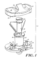
- Figure 1 is an exploded, perspective view of components of the system of the invention.
- Figure 2 is an isometric view of the system of the invention, assembled and mounted upon a tibia that is shown in phantom.
- Figure 3 illustrates an exploded perspective view of the trial tibial tray template element of the system together with a drill bushing and a bone drill bit.
- Figure 4 is an isometric view of a portion of the system of the invention illustrating the trial tibial tray template element mounted to a tibia, shown in phantom, with the drill bushing mounted to the element and a bone drill adjacent to the drill bushing.
- Figure 5 is an anterior view of the tibial punch.
- Figure 6 is a side sectional view of the tibial punch shown in Figure 5, at lines 6-6.
- Figure 7 is a detailed view of a portion of the wedge-like element of the tibial punch shown in Figure 5.
- Figure 8 is a top view of the trial tibial tray template element of the system.
- Figure 9 is a perspective view of a punch bushing of the system.
- Figure 10 is a side view of the punch bushing Figure 9.
- Figure 11 is a sectional view at lines 11-11 of the punch bushing shown in Figure 10.
- Figure 12 is a top view of the punch bushing of Figure 9.
- Figure 13 is a bottom view of a representative trial tibial bearing insert of the system of the invention.
- the modular bone preparation and trial system of the invention comprises various components that are useful to prepare the bone to receive a joint prothesis and also to evaluate the fit of various prosthesis components.
- These components include a trial tibial tray template element 12, punch bushing 16, tibial punch 18 and trial tibial bearing insert member 20.
- the system may optionally include a drill bushing 22 and a drill member 24, as shown in Figure 3.
- the trial tibial tray template element 12 has a superior surface 26 and an inferior surface 28, and anterior and posterior sides 25, 27.
- a guide aperture 30 is substantially centrally disposed on the element 12 and extends through the superior and inferior surfaces 26, 28 thereof.
- the trial tibial tray template element 12 preferably includes locking apertures 32 which may be disposed on opposite sides of the central aperture 30.
- at least two slots 34 extend radially, and preferably posteriorly, from the guide aperture 30. Slots 34 extend through the superior and inferior surfaces 26, 28 of element 12.
- the trial tibial tray template element 12 includes an anterior flange 36 that is slightly raised above the superior surface 26 of the element 12.
- Anterior flange 36 includes one or more apertures 38. Flange 36 and apertures 38 provide a mechanism to cooperate with a handle (not shown) used to manipulate and move the element 12.
- the guide aperture 30 may be substantially circular. In a preferred embodiment, however, the guide aperture 30 is substantially D-shaped and includes a perimeter having an arc portion 40 and a flat, non-arc portion 42.
- the D-shaped perimeter of the guide aperture is intended to help properly position and lock other components within the guide aperture 30, and it is understood that other profiles, besides D-shaped, may be employed.
- the non-arc portion 42 of the perimeter is adjacent an anterior side 25 of the trial element 12, but it is understood that this non-arc segment may be located at other portions of the perimeter.
- the nominal diameter (D m-1 ) of the guide aperture 30, measured in the medial-lateral plane, is in the range of about 1.0 to 1.30 inches.
- the nominal diameter (D a-p ) of the guide aperture 30, measured in the anterior-posterior plane is in the range of about 0.80 to 1.20 inches.
- the diameter of the guide aperture 30 may be lesser or greater than the values noted above.
- slots 34 extend radially from a portion of the guide aperture 30. Although preferred, it is not necessary that the trial tibial tray template element 12 include slots 34. However, when present, the slots should be of a length of approximately 1.00 to 1.50 inches and a width of about 0.15 to 0.38 inch. The slots 34 should extend completely through the template element 12 from the superior surface 26 to the inferior surface 28. The slots 34 may extend at any desired angular orientation from the guide aperture 34. In a preferred embodiment, however, the slots 34 are posteriorly directed and extend at an angle relative the transverse axis 46 of between 0 and 75 degrees in the posterior direction. In one embodiment, the slots 34 extend at an angle of between about 30 and 60 degrees, and most preferably at an angle of about 45 degrees. In another embodiment the angle formed by the slots 34 with the transverse axis 46 is 0 degrees. It is further understood that each of the slots 34 may extend at a different angle relative to transverse axis 46.
- the trial tibial tray template element 12 preferably includes one or more locking apertures 32 that are used to affix the elements 12 to the tibia when the element 12 is properly positioned.
- a locking mechanism such as bone penetrating pins 14, cooperates with the locking apertures 32 to affix the element 12 to the tibia.
- the pins 14 are elongate bone pins that are driven into the tibia to secure the elements 12 in position.
- Locking pins 14 preferably have a length in the range of about 10 to 25 mm and include a bone penetrating distal end 48.
- Figures 1, 2, 4 and 9-12 illustrate the punch bushing 16, which is an elongate member having proximal and distal ends 50, 52.
- the proximal end 50 preferably includes a collar 54 that is of a size and shape complementary to guide aperture 30.
- the collar 54 is sized to fit within guide aperture in a clearance fit such that a superior surface 56 of the collar 54 mounts in a manner such that it is slightly recessed or flush with respect to superior surface 26 of trial element 12.
- the guide aperture 30 includes a shoulder 58 that supports an inferior surface 60 of the collar 56 to ensure that the superior surface of the collar 54 is slightly recessed with respect to superior surface 26 of element 12.
- the collar 54 is substantially D-shaped having a perimeter with an arc portion 62 and a flat non-arc portion 64.
- the proximal end 50 and collar 54 of punch bushing 16 preferably include a central bore 68 that may be substantially circular in shape.
- the bore 68 extends at least partially into bushing 16.
- the bore 68 may have a diameter that is substantially constant along its entire length, or the diameter may vary with the depth of the bore.
- the bore has a substantially constant first diameter region 69 that extends over a majority of its length. Region 69 terminates in a restricted diameter region 70 that extends to the distal end 72 of the bore.
- Slots 35 preferably extend radially from bore 68.
- the slots 35 are intended to cooperate with slots 34 of trial element 12 to form a guide for the wedge-like fins 63 of tibial punch 18. As such, the size and orientation of slots 35 should be as described above for slots 34.
- slots 35 extend radially and posteriorly from the bore 68.
- the angle formed by each slot with the transverse axis 46 of the punch bushing 16 is in the range of about 0° to 75° in the posterior direction.
- the slots 35 extend at an angle from about 30° to 60°, and most preferably at an angle of about 45°.
- the slots 35 should have a length of about 5 to 50 mm and a width of about 2 to 8 mm.
- the slots 35 extend within the bore 68 to a depth of about 25 mm.
- the depth and diameter of the bore 68 may vary depending upon the requirements of a given application. Generally, the bore should be sized and shaped so as to accept the tibial punch, as described below. In an exemplary embodiment, however, the diameter of the bore is in the range of about 0.40 to 1.20 inches. In a preferred embodiment, illustrated in Figure 11, the diameter in region 69 is from about 0.80 to 1.00 inch. The length of the region 69 is about 1.2 to 2.0 inches. Further, the diameter of region 70 tapers at an angle of about 30° to 50° from about 0.70 to 0.50 inch. The length of region 70 is about 0.30 to 0.70 inch.
- the punch bushing 16 includes an outer surface 74.
- the outer surface 74 is intended to be implanted within the tibia to form a bone-contacting surface.
- the distal end 52 of punch bushing 16 preferably is spherical.
- the size and shape of the outer surface of punch bushing may vary depending upon the requirements of a given application. Generally, however, it is understood that the distal end 52 is intended to serve the purpose of a tibial stem prosthesis. Accordingly, it should be of a size and shape consistent with that desired for the distal portion of a permanent tibial tray prosthesis.
- the outer surface has a first region 76 that is disposed distally of the collar.
- a second region 78 is formed distally of the first region.
- the first region 76 has a diameter that tapers from a widest portion, at a proximal end of first region, to a narrowest portion at the distal-most end of the first region.
- the diameter of the widest portion of the first region 76 is approximately 0.90 to 1.00 inch.
- the taper of the first region 76 preferably extends at an angle of about 5 degrees to 6 degrees, and most preferably about 5.75 degrees.
- the diameter at the widest, most proximal portion of the second region 78 is in the range of about 0.60 to 0.70 inch, and most preferably is about 0.68 to 0.69 inch.
- the length of the first region 76 is approximately 1.0 to 1.2 inch while the length of the second region 78 is about 2.00 to 2.10 inch.
- the tibial punch 18 is a substantially wedged-shaped member that is inserted through the punch bushing 16 and into a patient's tibia 21 to form an opening in the bone that will be of a suitable size and shape to receive the fin elements of a prosthetic tibial tray (not shown).
- the tibial punch includes a hub 80 that is substantially elongate and cylindrical.
- Two wedge-like fins 63 which extend from opposite sides of the central hub 80, have a width that tapers from proximal to distal ends 82, 84 thereof.
- the outer edges 86 of the wedge-like fins are of a shape and/or configuration to facilitate bone penetration. In one embodiment the outer edges are serrated.
- a proximal end 88 of the tibial punch 18 includes a connecting element 90 that will protrude above the superior surface of trial element 12 when the system is fully assembled.
- the connecting element 90 preferably includes a base surface 92 that is normally horizontally oriented.
- the base surface 92 is separated from a top surface 94 by a vertical connecting surface 96.
- the top surface 94 is preferably horizontal.
- the connecting element 90 is configured to mate with a universal handle (not shown) which can receive blows from a mallet (not shown) while the punch 18 is being forced into a patient's tibia.
- the space between the base surface 92 and the top surface 94 forms a lip 100 that can be used to engage or mate with a trial tibial bearing insert 20, as described below.
- the size and shape of the tibial punch 18 should be such that it is able to fit within the bore 68 and slots 35 of the punch bushing 16 in a clearance fit. That is, the cylindrical hub 80 should be of substantially the same shape and a slightly smaller diameter than the bore 68 of the punch bushing 16. Similarly, the wedge-like fins 63 should extend from the hub 80 at substantially the same angle as do the slots extend from the bore of the punch bushing 16. Thus, the wedge-like fins 63 extend from the hub 80 at an angle, relative to the transverse axis 46, of between 0 and 75 degrees. In one embodiment the angle formed by fins 63 with the transverse axis 46 is from about 30 to 60 degrees, and most preferably, about 45 degrees. In another embodiment the angle formed by fins 63 with transverse axis 46 is 0 degrees. It is further understood that each of the fins 63 may extend at a different angle relative to transverse axis 46.
- the width of fins 63 tapers from the proximal to the distal ends 82, 84 of the tibial punch.
- the taper angle ⁇ can vary, but it preferably is in the range of about 50° to 65°.
- the width of the punch, at its widest point (measured from opposite edges of fins 63) is about 1.85 inches.
- the width tapers to about 0.65 inch at the narrowest portion of the tibial punch.
- each tooth 102 is separated from an adjacent tooth by a space 104. Further, each tooth 102 has a base, or distal, surface 106 that is oriented at an angle of approximately 65 degrees relative to the longitudinal axis 108 of the punch 18.
- the proximal surface 110 of each tooth includes a first component 112 that is substantially parallel to the base surface 106 and a canted face 114 which meets the base surface 106 at apex 116. The canted face 114 forms an angle of approximately 45 degrees with the base surface 106.
- the trial tibial bearing member 20 is of a type that is known in the art to be useful for evaluating the fit of a prosthesis.
- the system 10 includes one or more of the trial tibial bearing members 20 in various sizes and orientations.
- the trial tibial bearing insert 20 includes a superior articulation surface 118 which may have one or more condylar elements 120.
- an inferior surface 122 which is adapted to mate with the connecting surface of the tibial punch, rests on superior surface of the trial tibial tray template element 12 when the system is fully assembled.
- Inferior surface 122 preferably includes a mating aperture 124 that is adapted to house the connecting surface of the tibial punch removably and replaceably mate to bearing insert 20 to the rest of the system.
- the system 10 of the invention is used in the following manner.
- the proximal surface of a tibia 21 is resected in a known manner and the trial element 12 is then properly positioned on the resected tibia and secured in place on a tibia by the locking pins 14.
- the drill bushing 22 is then attached to the trial element 12 by mating dowel pins (not shown) on an inferior surface of drill bushing 22 with holes 33 of element 12, and then drill element 24 is inserted through the bushing 22 and used to form a cavity of a desired depth and diameter within the tibia 21. Once the cavity is formed the drill element 24 and drill bushing 22 are removed.
- the punch bushing 16 is then mounted upon trial element 12 such that the distal end 52 of the punch bushing 16 is inserted into the cavity within the tibia and the collar 54 mounts within the guide aperture 30 of trial element 12.
- the tibial punch 18 is then inserted into the bore 68 and slots 35 of the guide bushing 16 and is forced into the tibia (e.g., by hammering) until the underside 93 of base surface 92 contacts the superior surface 56 of collar 54.
- the components of the system used to prepare the bone (e.g., the punch bushing and the tibial punch) remain in place once the bone has been prepared and, together with trial element 12 and trial tibial bearing element 20, serve as components of the trial system.
- the tibial punch 18 is properly positioned it is left in place, as noted above, and a surgeon can attach one or more trial tibial bearing elements 20 to the connecting surface 90 so as to form a full trial tibial prosthesis.
- the size and fit of the various trial tibial bearing inserts are evaluated and the surgeon determines the proper components to use in a prosthetic joint, and the proper orientation of such components, Thereafter, the components of the system are removed and are replaced with permanent prosthesis components in a manner known in the art.
Abstract
Description
Claims (18)
- A bone preparation and trial system, comprising:at least one trial tibial tray template element having a superior surface and a bone-contacting inferior surface with at least one guide aperture extending through the element from the superior to the inferior surfaces thereof;at least one locking aperture formed in the trial tibial tray template element;at least one punch bushing in the form of an elongate member selectively matable within the at least one guide aperture of the trial tibial tray template element, the punch bushing having a distal end adapted to mate within a patient's tibia and a proximal end having a collar matable with the guide aperture, the collar including a centrally disposed bore extending at least partially into the punch bushing and a pair of opposed slots, each opposed slot extending radially from the bore and extending at least partially into the punch bushing;at least one tibial punch insertable within the bore and slots of the punch bushing to create an opening within the patient's tibia of a size and shape complementary to the tibial punch, the tibial punch having distal and proximal ends whereina wedge-like member, formed on the distal end thereof, includes opposed fins with bone-penetrating outer surfaces, the opposed fins being adapted for mating within the slots of the punch bushing, anda connecting element, formed on the proximal end thereof; andat least one trial tibial bearing insert, each trial tibial bearing insert having a superior articulation surface and an inferior mating surface adapted to mount upon the superior surface of the trial tibial tray template element, the inferior mating surface further including a mating aperture matable with the connecting element of the tibial punch.
- The system of claim 1 wherein the guide aperture is substantially round.
- The system of claim 1 wherein the aperture is substantially D-shaped, having an arc portion and a flat, non-arc portion.
- The system of claim 3 wherein the flat, non-arc portion is disposed adjacent an anterior portion of the trial tibial tray template element.
- The system of claim 1 wherein the guide aperture has a nominal diameter, measured in the medial-lateral plane, in the range of about 1.00 to 1.30 inches.
- The system of claim 1 wherein the guide aperture has a nominal diameter, measured in the anterior-posterior plane, in the range of about 0.80 to 1.20 inches.
- The system of claim 3 wherein the collar of the punch bushing is substantially D-shaped and is sized to fit within the guide aperture in a clearance fit such that in a fully mated position a superior surface of the collar is slightly recessed with respect to the superior surface of the trial tibial tray template element.
- The system of claim 1 wherein the locking apertures are formed on opposite sides of the guide aperture.
- The system of claim 8, further comprising a plurality of locking pins removably insertable within the locking aperture to selectively secure the trial tibial tray template element to a patient's tibia.
- The system of claim 1 wherein the slots of the punch bushing extend at an angle of 0° with respect to a transverse axis of the punch bushing.
- The system of claim 1 wherein the slots of the punch bushing extend posteriorly.
- The system of claim 11 wherein the slots form an angle with respect to the transverse axis of the trial tibial tray template element in the range of about 30° to 60°.
- The system of claim 11 wherein the length of each slot is about 1.00 to 1.50 inches.
- The system of claim 1 wherein the bone-penetrating outer surfaces of the wedge-like member are serrated.
- The system of claim 1, wherein the connecting element comprisesa base portion;a vertical connecting wall to oriented transversely to the base portion; anda top surface appended to the vertical connecting well and spaced apart from the base portion.
- The system of claim 1 further comprising a drill bushing removably mountable upon the superior surface of the trial tibial tray template element.
- A bone preparation and trial system, comprising:at least one trial tibial tray template element having a superior surface and a bone-contacting inferior surface with at least one guide aperture extending through the element from the superior to the inferior surfaces thereof, the guide aperture including a pair of opposed slots extending radially from the guide aperture;locking means for selectively securing the trial tibial tray template element to a patient's tibia;at least one punch bushing in the form of an elongate member having proximal end that includes a mating collar and a distal end, the mating collar being selectively matable within the at least one guide aperture of the trial tibial tray template element, and the distal end being adapted to mate within a patient's tibia, the punch bushing further including a centrally disposed bore and a pair of opposed slots extending radially from the bore, each of the bore and the slots extending distally from the collar at least partially into the punch bushing;at least one tibial punch having a central hub with opposed fins extending radially therefrom, each opposed fin tapering in width from a proximal end to a distal end, the central hub and the opposed fins being sized and oriented to be selectively insertable within the bore and slots of the punch bushing to create an opening within the patient's tibia of a size and shape complementary to the tibial punch, the central hub further including a connecting element formed on the proximal end thereof and having a top, impact surface; andat least one trial tibial bearing insert, each trial tibial bearing insert having a superior articulation surface and an inferior mating surface that is adapted to mount upon the superior surface of the trial tibial tray template element, the inferior mating surface further including a mating aperture matable with the connecting element of the tibial punch.
- The system of claim 17 wherein the punch bushing tapers in diameter from the collar to the distal end thereof.
Applications Claiming Priority (2)
| Application Number | Priority Date | Filing Date | Title |
|---|---|---|---|
| US890784 | 1997-07-11 | ||
| US08/890,784 US5976147A (en) | 1997-07-11 | 1997-07-11 | Modular instrumentation for bone preparation and implant trial reduction of orthopedic implants |
Publications (3)
| Publication Number | Publication Date |
|---|---|
| EP0890340A2 true EP0890340A2 (en) | 1999-01-13 |
| EP0890340A3 EP0890340A3 (en) | 1999-07-14 |
| EP0890340B1 EP0890340B1 (en) | 2006-05-03 |
Family
ID=25397140
Family Applications (1)
| Application Number | Title | Priority Date | Filing Date |
|---|---|---|---|
| EP98305492A Expired - Lifetime EP0890340B1 (en) | 1997-07-11 | 1998-07-10 | Modular instrumentation for bone preparation and implant trial reduction of orthopedic implants |
Country Status (7)
| Country | Link |
|---|---|
| US (1) | US5976147A (en) |
| EP (1) | EP0890340B1 (en) |
| JP (1) | JP4040758B2 (en) |
| AU (1) | AU727550B2 (en) |
| CA (1) | CA2242798C (en) |
| DE (1) | DE69834363T2 (en) |
| ES (1) | ES2263191T3 (en) |
Cited By (4)
| Publication number | Priority date | Publication date | Assignee | Title |
|---|---|---|---|---|
| WO2006088684A1 (en) * | 2005-02-17 | 2006-08-24 | Zimmer Technology, Inc. | Tibial trialing assembly and method of trialing a tibial implant |
| EP2939615A1 (en) * | 2014-04-30 | 2015-11-04 | DePuy (Ireland) | Tibial trial system for a knee prosthesis |
| CN105813587A (en) * | 2013-12-24 | 2016-07-27 | 科润泰克株式会社 | Patient-customized surgical instrument for tibia and surgical module using same |
| US10195056B2 (en) | 2015-10-19 | 2019-02-05 | Depuy Ireland Unlimited Company | Method for preparing a patient's tibia to receive an implant |
Families Citing this family (137)
| Publication number | Priority date | Publication date | Assignee | Title |
|---|---|---|---|---|
| US6063091A (en) * | 1998-10-13 | 2000-05-16 | Stryker Technologies Corporation | Methods and tools for tibial intermedullary revision surgery and associated tibial components |
| US6206928B1 (en) * | 1999-04-29 | 2001-03-27 | Depuy Orthpaedics, Inc. | Orthopaedic tray trial |
| US6558426B1 (en) | 2000-11-28 | 2003-05-06 | Medidea, Llc | Multiple-cam, posterior-stabilized knee prosthesis |
| US6942670B2 (en) | 2000-12-27 | 2005-09-13 | Depuy Orthopaedics, Inc. | Prosthesis evaluation assembly and associated method |
| US6355045B1 (en) * | 2000-12-28 | 2002-03-12 | Depuy Orthopaedics, Inc. | Method and apparatus for surgically preparing a tibia for implantation of a prosthetic implant component which has an offset stem |
| US6537300B2 (en) | 2001-05-30 | 2003-03-25 | Scimed Life Systems, Inc. | Implantable obstruction device for septal defects |
| US6482209B1 (en) | 2001-06-14 | 2002-11-19 | Gerard A. Engh | Apparatus and method for sculpting the surface of a joint |
| US6723102B2 (en) | 2001-06-14 | 2004-04-20 | Alexandria Research Technologies, Llc | Apparatus and method for minimally invasive total joint replacement |
| EP1476097A4 (en) | 2002-02-20 | 2010-12-08 | Zimmer Inc | Knee arthroplasty prosthesis and method |
| US7799086B2 (en) * | 2002-04-25 | 2010-09-21 | Zimmer Technology, Inc. | Modular bone implant, tools, and method |
| US6902583B2 (en) | 2002-04-25 | 2005-06-07 | Medicinelodge, Inc. | Tripartite attachment mechanism and method for a modular prosthesis |
| US7105021B2 (en) * | 2002-04-25 | 2006-09-12 | Scimed Life Systems, Inc. | Implantable textile prostheses having PTFE cold drawn yarns |
| US6875239B2 (en) | 2002-04-25 | 2005-04-05 | Medicinelodge, Inc. | Modular prosthesis for replacing bone and method |
| US7182786B2 (en) * | 2002-04-25 | 2007-02-27 | Zimmer Technology, Inc. | Modular bone implant, tool, and method |
| AU2003237813A1 (en) * | 2002-05-09 | 2003-11-11 | Hayes Medical, Inc. | System for establishing the orientation of a modular implant |
| WO2004037119A2 (en) | 2002-10-23 | 2004-05-06 | Mako Surgical Corp. | Modular femoral component for a total knee joint replacement for minimally invasive implantation |
| US20040102852A1 (en) | 2002-11-22 | 2004-05-27 | Johnson Erin M. | Modular knee prosthesis |
| US6887276B2 (en) | 2002-12-13 | 2005-05-03 | Medicine Lodge, Inc | Modular implant for joint reconstruction and method of use |
| US6866683B2 (en) | 2002-12-13 | 2005-03-15 | Medicine Lodge, Inc. | Modular implant for joint reconstruction and method of use |
| US7854737B2 (en) * | 2002-12-20 | 2010-12-21 | Depuy Products, Inc. | Instrument and associated method of trailing for modular hip stems |
| US7235106B2 (en) | 2002-12-20 | 2007-06-26 | Depuy Products, Inc. | Modular hip stems and associated method of trialing |
| US20040122439A1 (en) * | 2002-12-20 | 2004-06-24 | Dwyer Kimberly A. | Adjustable biomechanical templating & resection instrument and associated method |
| US7022141B2 (en) * | 2002-12-20 | 2006-04-04 | Depuy Products, Inc. | Alignment device for modular implants and method |
| US7297166B2 (en) | 2003-06-25 | 2007-11-20 | Depuy Products, Inc. | Assembly tool for modular implants and associated method |
| US8998919B2 (en) | 2003-06-25 | 2015-04-07 | DePuy Synthes Products, LLC | Assembly tool for modular implants, kit and associated method |
| US7582092B2 (en) | 2003-06-25 | 2009-09-01 | Depuy Products, Inc. | Assembly tool for modular implants and associated method |
| US20040267267A1 (en) * | 2003-06-25 | 2004-12-30 | Daniels David Wayne | Non-linear reamer for bone preparation and associated method |
| US7074224B2 (en) | 2003-06-25 | 2006-07-11 | Depuy Products, Inc. | Modular tapered reamer for bone preparation and associated method |
| US8048169B2 (en) * | 2003-07-28 | 2011-11-01 | Baronova, Inc. | Pyloric valve obstructing devices and methods |
| US7390327B2 (en) * | 2003-10-03 | 2008-06-24 | Howmedica Osteonics Corp. | Punch apparatus and method for surgery |
| US7785328B2 (en) * | 2003-12-30 | 2010-08-31 | Depuy Products, Inc. | Minimally invasive bone miller apparatus |
| US8025663B2 (en) * | 2003-12-30 | 2011-09-27 | Depuy Products, Inc. | Augments for surgical instruments |
| US7832405B1 (en) * | 2004-08-25 | 2010-11-16 | Biomet Manufacturing Corp. | Method and apparatus for assembling implants |
| US7524334B2 (en) * | 2004-11-29 | 2009-04-28 | Haidukewych George J | Tibial tray for total knee arthroplasty |
| US20060200248A1 (en) * | 2005-03-03 | 2006-09-07 | Laurent Beguin | Prosthesis for the glenoid cavity of the scapula |
| AU2006247498A1 (en) | 2005-05-18 | 2006-11-23 | Sonoma Orthopedic Products, Inc. | Minimally invasive actuable bone fixation devices, systems and methods of use |
| US8961516B2 (en) | 2005-05-18 | 2015-02-24 | Sonoma Orthopedic Products, Inc. | Straight intramedullary fracture fixation devices and methods |
| US7909825B2 (en) | 2006-11-22 | 2011-03-22 | Sonoma Orthepedic Products, Inc. | Fracture fixation device, tools and methods |
| US9060820B2 (en) | 2005-05-18 | 2015-06-23 | Sonoma Orthopedic Products, Inc. | Segmented intramedullary fracture fixation devices and methods |
| US8287541B2 (en) | 2005-05-18 | 2012-10-16 | Sonoma Orthopedic Products, Inc. | Fracture fixation device, tools and methods |
| EP1787603A1 (en) | 2005-11-18 | 2007-05-23 | Zimmer GmbH | Basis-platform for an artificial joint |
| US8597298B2 (en) | 2006-09-29 | 2013-12-03 | DePuy Synthes Products, LLC | Proximal reamer |
| US8491587B2 (en) * | 2006-12-21 | 2013-07-23 | Howmedica Osteonics Corp. | Adjustable offset bushing |
| JP5285227B2 (en) * | 2007-02-26 | 2013-09-11 | 京セラメディカル株式会社 | Bioprosthesis |
| US20080255574A1 (en) * | 2007-04-13 | 2008-10-16 | Zimmer Technology, Inc. | Instrument for insertion of prosthetic components |
| US7985226B2 (en) * | 2007-05-04 | 2011-07-26 | Mcallister Craig M | Distal femoral cutting guide |
| US8632600B2 (en) | 2007-09-25 | 2014-01-21 | Depuy (Ireland) | Prosthesis with modular extensions |
| US8128703B2 (en) | 2007-09-28 | 2012-03-06 | Depuy Products, Inc. | Fixed-bearing knee prosthesis having interchangeable components |
| US9204967B2 (en) | 2007-09-28 | 2015-12-08 | Depuy (Ireland) | Fixed-bearing knee prosthesis having interchangeable components |
| US8556912B2 (en) | 2007-10-30 | 2013-10-15 | DePuy Synthes Products, LLC | Taper disengagement tool |
| US8518050B2 (en) | 2007-10-31 | 2013-08-27 | DePuy Synthes Products, LLC | Modular taper assembly device |
| US8435241B2 (en) * | 2007-12-20 | 2013-05-07 | Depuy Products, Inc. | Keel punch impactor with connection device |
| US8287547B2 (en) * | 2008-06-23 | 2012-10-16 | Depuy Products, Inc. | Adjustable drill guide |
| US8236061B2 (en) | 2008-06-30 | 2012-08-07 | Depuy Products, Inc. | Orthopaedic knee prosthesis having controlled condylar curvature |
| US8192498B2 (en) | 2008-06-30 | 2012-06-05 | Depuy Products, Inc. | Posterior cructiate-retaining orthopaedic knee prosthesis having controlled condylar curvature |
| US9168145B2 (en) | 2008-06-30 | 2015-10-27 | Depuy (Ireland) | Posterior stabilized orthopaedic knee prosthesis having controlled condylar curvature |
| US9119723B2 (en) | 2008-06-30 | 2015-09-01 | Depuy (Ireland) | Posterior stabilized orthopaedic prosthesis assembly |
| US8187335B2 (en) | 2008-06-30 | 2012-05-29 | Depuy Products, Inc. | Posterior stabilized orthopaedic knee prosthesis having controlled condylar curvature |
| US8828086B2 (en) | 2008-06-30 | 2014-09-09 | Depuy (Ireland) | Orthopaedic femoral component having controlled condylar curvature |
| US8206451B2 (en) | 2008-06-30 | 2012-06-26 | Depuy Products, Inc. | Posterior stabilized orthopaedic prosthesis |
| EP2341857A2 (en) | 2008-09-26 | 2011-07-13 | Sonoma Orthopedic Products, Inc. | Bone fixation device, tools and methods |
| US8167882B2 (en) | 2008-09-30 | 2012-05-01 | Depuy Products, Inc. | Minimally invasive bone miller apparatus |
| US8740911B2 (en) * | 2008-11-07 | 2014-06-03 | Howmedica Osteonics Corp. | Method of preparing a femur for implantation of a femoral implant |
| US9375221B2 (en) | 2008-12-29 | 2016-06-28 | Depuy (Ireland) | Orthopaedic cutting block having a chemically etched metal insert |
| US20100168752A1 (en) * | 2008-12-29 | 2010-07-01 | Edwards Jon M | Orthopaedic cutting tool having a chemically etched metal insert and method of manufacturing |
| US8551023B2 (en) | 2009-03-31 | 2013-10-08 | Depuy (Ireland) | Device and method for determining force of a knee joint |
| US8721568B2 (en) | 2009-03-31 | 2014-05-13 | Depuy (Ireland) | Method for performing an orthopaedic surgical procedure |
| CA2764002A1 (en) * | 2009-05-29 | 2010-12-02 | Smith & Nephew, Inc. | Methods and apparatus for performing knee arthroplasty |
| US8998997B2 (en) | 2009-08-11 | 2015-04-07 | Michael D. Ries | Implantable mobile bearing prosthetics |
| US9095453B2 (en) * | 2009-08-11 | 2015-08-04 | Michael D. Ries | Position adjustable trial systems for prosthetic implants |
| US8382848B2 (en) * | 2009-08-11 | 2013-02-26 | Imds Corporation | Position adjustable trial systems for prosthetic implants |
| US9011547B2 (en) | 2010-01-21 | 2015-04-21 | Depuy (Ireland) | Knee prosthesis system |
| GB201006716D0 (en) | 2010-04-22 | 2010-06-09 | Depuy Ireland | A composite trial prosthesis |
| US8533921B2 (en) | 2010-06-15 | 2013-09-17 | DePuy Synthes Products, LLC | Spiral assembly tool |
| CA2806326C (en) | 2010-07-24 | 2020-01-07 | Zimmer, Inc. | Asymmetric tibial components for a knee prosthesis |
| US8764840B2 (en) | 2010-07-24 | 2014-07-01 | Zimmer, Inc. | Tibial prosthesis |
| US9095452B2 (en) | 2010-09-01 | 2015-08-04 | DePuy Synthes Products, Inc. | Disassembly tool |
| EP2613739B1 (en) | 2010-09-10 | 2017-06-07 | Zimmer, Inc. | Motion facilitating tibial components for a knee prosthesis |
| US8317870B2 (en) | 2010-09-30 | 2012-11-27 | Depuy Products, Inc. | Tibial component of a knee prosthesis having an angled cement pocket |
| US8287601B2 (en) | 2010-09-30 | 2012-10-16 | Depuy Products, Inc. | Femoral component of a knee prosthesis having an angled cement pocket |
| US20120089146A1 (en) | 2010-10-06 | 2012-04-12 | Howmedica Osteonics Corp. | System and method of bone preparation |
| US8603101B2 (en) | 2010-12-17 | 2013-12-10 | Zimmer, Inc. | Provisional tibial prosthesis system |
| US9597090B2 (en) | 2010-12-17 | 2017-03-21 | Zimmer, Inc. | Cut guide attachment for use in tibial prosthesis systems |
| CN103813764B (en) | 2011-04-06 | 2017-04-19 | 德普伊新特斯产品有限责任公司 | Instrument assembly for implanting revision hip prosthesis and orthopaedic surgical procedure for using same |
| US8979847B2 (en) | 2011-06-06 | 2015-03-17 | Biomet Manufacturing, Llc | Method and apparatus for implanting a knee prosthesis |
| US8986390B2 (en) | 2011-06-30 | 2015-03-24 | Depuy (Ireland) | Method of trialing a knee prosthesis |
| USD666713S1 (en) * | 2011-06-30 | 2012-09-04 | Depuy Products, Inc. | Tibial keel punch |
| US8968412B2 (en) * | 2011-06-30 | 2015-03-03 | Depuy (Ireland) | Trialing system for a knee prosthesis and method of use |
| US8939986B2 (en) | 2011-06-30 | 2015-01-27 | Depuy (Ireland) | Surgical instruments for use in surgically preparing a tibia for implantation of a prosthetic component |
| US8951301B2 (en) | 2011-06-30 | 2015-02-10 | Depuy (Ireland) | Method of using a trialing system for a knee prosthesis |
| US8852197B2 (en) | 2011-06-30 | 2014-10-07 | Depuy (Ireland) | Surgical instrument assemblies for use in surgically preparing a tibia for implantation of a prosthetic component |
| US8926619B2 (en) | 2011-06-30 | 2015-01-06 | Depuy (Ireland) | Method of surgically preparing a tibia for implantation of a prosthetic component |
| US11000387B2 (en) | 2011-09-02 | 2021-05-11 | Episurf Ip-Management Ab | Implant for cartilage repair |
| EP2564792A1 (en) * | 2011-09-02 | 2013-03-06 | Episurf Medical AB | Modular surgical kit for cartilage repair |
| US10603049B2 (en) | 2011-09-02 | 2020-03-31 | Episurf Ip-Management Ab | Implant specific drill bit in surgical kit for cartilage repair |
| US8858643B2 (en) | 2011-11-18 | 2014-10-14 | Zimmer, Inc. | Tibial bearing component for a knee prosthesis with improved articular characteristics |
| ES2585838T3 (en) | 2011-11-21 | 2016-10-10 | Zimmer, Inc. | Tibial base plate with asymmetric placement of fixing structures |
| EP2787901B1 (en) | 2011-12-09 | 2017-06-07 | Howmedica Osteonics Corp. | Surgical reaming instrument for shaping a bone cavity |
| US9149282B2 (en) | 2011-12-30 | 2015-10-06 | Howmedica Osteonics Corp. | Systems and methods for preparing bone voids to receive a prosthesis |
| CA2863375C (en) | 2012-01-30 | 2019-07-16 | Mary S.S. Wentorf | Asymmetric tibial components for a knee prosthesis |
| US9795392B2 (en) * | 2012-02-06 | 2017-10-24 | Arthrex, Inc. | Surgical instrumentation set and surgical technique |
| US9381011B2 (en) | 2012-03-29 | 2016-07-05 | Depuy (Ireland) | Orthopedic surgical instrument for knee surgery |
| US9492290B2 (en) | 2012-03-30 | 2016-11-15 | Zimmer, Inc. | Tibial prosthesis systems, kits, and methods |
| US10206792B2 (en) | 2012-03-31 | 2019-02-19 | Depuy Ireland Unlimited Company | Orthopaedic surgical system for determining joint forces of a patients knee joint |
| US10070973B2 (en) | 2012-03-31 | 2018-09-11 | Depuy Ireland Unlimited Company | Orthopaedic sensor module and system for determining joint forces of a patient's knee joint |
| US9028501B2 (en) | 2012-05-30 | 2015-05-12 | Depuy (Ireland) | Tibial orthopaedic surgical instruments and method of using same |
| US9113915B2 (en) | 2012-05-30 | 2015-08-25 | Depuy (Ireland) | Method of surgically preparing a patient's tibia |
| US9095356B2 (en) * | 2012-05-30 | 2015-08-04 | Depuy (Ireland) | Tibial trial instruments and method of using same |
| WO2014127229A1 (en) * | 2013-02-14 | 2014-08-21 | Zimmer, Inc. | Trialing for prosthetic component |
| US9107757B2 (en) * | 2013-03-13 | 2015-08-18 | Depuy (Ireland) | Tibial trial instruments for setting offset |
| US9526513B2 (en) | 2013-03-13 | 2016-12-27 | Howmedica Osteonics Corp. | Void filling joint prosthesis and associated instruments |
| US9925052B2 (en) | 2013-08-30 | 2018-03-27 | Zimmer, Inc. | Method for optimizing implant designs |
| US9592133B2 (en) | 2013-09-23 | 2017-03-14 | Zimmer, Inc. | Spacer block |
| US9770278B2 (en) | 2014-01-17 | 2017-09-26 | Arthrex, Inc. | Dual tip guide wire |
| US20170172744A1 (en) | 2014-07-09 | 2017-06-22 | Episurf Ip-Management Ab | Surgical joint implant and a bone-mountable rig |
| WO2016004991A1 (en) | 2014-07-09 | 2016-01-14 | Episurf Ip-Management Ab | Customized implant for cartilage repair and corresponding method of design |
| US9814499B2 (en) | 2014-09-30 | 2017-11-14 | Arthrex, Inc. | Intramedullary fracture fixation devices and methods |
| US10149763B2 (en) | 2015-01-12 | 2018-12-11 | Howmedica Osteonics Corp. | Multipurpose void filling prosthesis |
| WO2016172026A1 (en) | 2015-04-20 | 2016-10-27 | The Board Of Regents Of The University Of Texas System | Clec11a is a bone growth agent |
| JP7143079B2 (en) * | 2015-05-06 | 2022-09-28 | カルティヒール(2009)リミティド | Optimized solid substrates, tools for use therewith and their use for promoting cell and tissue growth |
| US9668883B2 (en) * | 2015-08-19 | 2017-06-06 | Depuy Ireland Unlimited Company | Trial kit for knee prosthesis system |
| WO2017053196A1 (en) | 2015-09-21 | 2017-03-30 | Zimmer, Inc. | Prosthesis system including tibial bearing component |
| US10537445B2 (en) | 2015-10-19 | 2020-01-21 | Depuy Ireland Unlimited Company | Surgical instruments for preparing a patient's tibia to receive an implant |
| RU2742969C2 (en) | 2016-05-18 | 2021-02-12 | Депью Айэлэнд Анлимитед Компани | System for tibial preparation of patient in orthopedic operation of replacement arthroplasty |
| US10363148B2 (en) | 2016-05-18 | 2019-07-30 | Depuy Ireland Unlimited Company | Method for preparing a patient's femur in an orthopaedic joint replacement procedure |
| WO2017201272A2 (en) | 2016-05-18 | 2017-11-23 | Depuy Ireland Unlimited Company | Orthopaedic surgical instrument system for surgically-preparing a patient's femur |
| US10470900B2 (en) * | 2016-06-17 | 2019-11-12 | Paragon 28, Inc. | Implants, devices, systems, kits and methods of implanting |
| JP6788459B2 (en) * | 2016-09-28 | 2020-11-25 | 京セラ株式会社 | Instrument for total knee arthroplasty |
| US20180125667A1 (en) * | 2016-11-07 | 2018-05-10 | John Bodeker Savage | Prosthetic apparatus and systems for total knee arthroplasty |
| CN110402123B (en) | 2017-03-10 | 2022-02-08 | 捷迈有限公司 | Tibial prosthesis with tibial bearing component fastening features |
| CN110636818B (en) | 2017-05-12 | 2021-06-04 | 捷迈有限公司 | Femoral prosthesis with size augmentation and size reduction capabilities |
| US10543001B2 (en) | 2017-09-20 | 2020-01-28 | Depuy Ireland Unlimited Company | Method and instruments for assembling a femoral orthopaedic prosthesis |
| US10537341B2 (en) | 2017-09-20 | 2020-01-21 | Depuy Ireland Unlimited Company | Orthopaedic system and method for assembling prosthetic components |
| US10537446B2 (en) | 2017-09-20 | 2020-01-21 | Depuy Ireland Unlimited Company | Method and instruments for assembling an orthopaedic prosthesis |
| US11426282B2 (en) | 2017-11-16 | 2022-08-30 | Zimmer, Inc. | Implants for adding joint inclination to a knee arthroplasty |
| US10835380B2 (en) | 2018-04-30 | 2020-11-17 | Zimmer, Inc. | Posterior stabilized prosthesis system |
| GB201913436D0 (en) | 2019-09-18 | 2019-10-30 | Depuy Ireland Ultd Co | Cutting block |
Citations (3)
| Publication number | Priority date | Publication date | Assignee | Title |
|---|---|---|---|---|
| US4759350A (en) | 1986-10-17 | 1988-07-26 | Dunn Harold K | Instruments for shaping distal femoral and proximal tibial surfaces |
| US5609642A (en) | 1995-02-15 | 1997-03-11 | Smith & Nephew Richards Inc. | Tibial trial prosthesis and bone preparation system |
| US5628749A (en) | 1995-02-15 | 1997-05-13 | Smith & Nephew Richards Inc. | Tibial resection instrumentation and surgical method |
Family Cites Families (11)
| Publication number | Priority date | Publication date | Assignee | Title |
|---|---|---|---|---|
| US4211228A (en) * | 1979-01-24 | 1980-07-08 | Cloutier Jean Marie | Multipurpose tibial template |
| US4736737A (en) * | 1986-03-31 | 1988-04-12 | William Fargie | Tibial cutting jig |
| US4952213A (en) * | 1989-02-03 | 1990-08-28 | Boehringer Mannheim Corporation | Tibial cutting guide |
| US5282866A (en) * | 1992-02-12 | 1994-02-01 | Osteonics Corp. | Prosthetic knee tibial component with axially ribbed keel and apparatus for effecting implant |
| US5176684A (en) * | 1992-02-20 | 1993-01-05 | Dow Corning Wright | Modular shaping and trial reduction guide for implantation of posterior-stabilized femoral prosthesis and method of using same |
| US5275603A (en) * | 1992-02-20 | 1994-01-04 | Wright Medical Technology, Inc. | Rotationally and angularly adjustable tibial cutting guide and method of use |
| US5342368A (en) * | 1992-07-08 | 1994-08-30 | Petersen Thomas D | Intramedullary universal proximal tibial resector guide |
| US5431656A (en) * | 1994-02-04 | 1995-07-11 | Wright Medical Technology, Inc. | Intramedullary instrumentation to position means for preparing a tibial plateau with a posterior slope |
| US5520692A (en) * | 1995-02-28 | 1996-05-28 | Wright Medical Technology, Inc. | Adjustable depth patella recessing guide and method |
| US5613970A (en) * | 1995-07-06 | 1997-03-25 | Zimmer, Inc. | Orthopaedic instrumentation assembly having an offset bushing |
| US5634927A (en) * | 1995-07-06 | 1997-06-03 | Zimmer, Inc. | Sizing plate and drill guide assembly for orthopaedic knee instrumentation |
-
1997
- 1997-07-11 US US08/890,784 patent/US5976147A/en not_active Expired - Lifetime
-
1998
- 1998-07-03 AU AU74168/98A patent/AU727550B2/en not_active Ceased
- 1998-07-09 CA CA002242798A patent/CA2242798C/en not_active Expired - Fee Related
- 1998-07-10 JP JP21030698A patent/JP4040758B2/en not_active Expired - Fee Related
- 1998-07-10 DE DE69834363T patent/DE69834363T2/en not_active Expired - Lifetime
- 1998-07-10 EP EP98305492A patent/EP0890340B1/en not_active Expired - Lifetime
- 1998-07-10 ES ES98305492T patent/ES2263191T3/en not_active Expired - Lifetime
Patent Citations (3)
| Publication number | Priority date | Publication date | Assignee | Title |
|---|---|---|---|---|
| US4759350A (en) | 1986-10-17 | 1988-07-26 | Dunn Harold K | Instruments for shaping distal femoral and proximal tibial surfaces |
| US5609642A (en) | 1995-02-15 | 1997-03-11 | Smith & Nephew Richards Inc. | Tibial trial prosthesis and bone preparation system |
| US5628749A (en) | 1995-02-15 | 1997-05-13 | Smith & Nephew Richards Inc. | Tibial resection instrumentation and surgical method |
Cited By (11)
| Publication number | Priority date | Publication date | Assignee | Title |
|---|---|---|---|---|
| WO2006088684A1 (en) * | 2005-02-17 | 2006-08-24 | Zimmer Technology, Inc. | Tibial trialing assembly and method of trialing a tibial implant |
| CN105813587A (en) * | 2013-12-24 | 2016-07-27 | 科润泰克株式会社 | Patient-customized surgical instrument for tibia and surgical module using same |
| EP3087938A4 (en) * | 2013-12-24 | 2017-11-01 | Corentec Co., Ltd. | Patient-customized surgical instrument for tibia and surgical module using same |
| EP2939615A1 (en) * | 2014-04-30 | 2015-11-04 | DePuy (Ireland) | Tibial trial system for a knee prosthesis |
| EP3117783A1 (en) * | 2014-04-30 | 2017-01-18 | DePuy Ireland Unlimited Company | Tibial trial system for a knee prosthesis |
| US9861491B2 (en) | 2014-04-30 | 2018-01-09 | Depuy Ireland Unlimited Company | Tibial trial system for a knee prosthesis |
| US10265183B2 (en) | 2014-04-30 | 2019-04-23 | Depuy Ireland Unlimited Company | Tibial trial system for a knee prosthesis and method |
| US10952863B2 (en) | 2014-04-30 | 2021-03-23 | Depuy Ireland Unlimited Company | Tibial trial system for a knee prosthesis and method |
| US11684479B2 (en) | 2014-04-30 | 2023-06-27 | Depuy Ireland Unlimited Company | Tibial trial system for a knee prosthesis and method |
| US10195056B2 (en) | 2015-10-19 | 2019-02-05 | Depuy Ireland Unlimited Company | Method for preparing a patient's tibia to receive an implant |
| US10952874B2 (en) | 2015-10-19 | 2021-03-23 | Depuy Ireland Unlimited Company | Method for preparing a patient's tibia to receive an implant |
Also Published As
| Publication number | Publication date |
|---|---|
| EP0890340B1 (en) | 2006-05-03 |
| DE69834363T2 (en) | 2007-03-15 |
| CA2242798A1 (en) | 1999-01-11 |
| AU727550B2 (en) | 2000-12-14 |
| AU7416898A (en) | 1999-01-21 |
| EP0890340A3 (en) | 1999-07-14 |
| CA2242798C (en) | 2007-02-06 |
| DE69834363D1 (en) | 2006-06-08 |
| US5976147A (en) | 1999-11-02 |
| ES2263191T3 (en) | 2006-12-01 |
| JP4040758B2 (en) | 2008-01-30 |
| JPH11104155A (en) | 1999-04-20 |
Similar Documents
| Publication | Publication Date | Title |
|---|---|---|
| US5976147A (en) | Modular instrumentation for bone preparation and implant trial reduction of orthopedic implants | |
| EP2837365B1 (en) | Tibial orthopaedic surgical instrument | |
| US5683469A (en) | Tibial trial prosthesis and bone preparation system | |
| US5062852A (en) | Tibial prosthesis with independent medial and lateral baseplates | |
| EP2042111B1 (en) | Modular Femoral Orthopaedic Surgical Instrument | |
| US5702463A (en) | Tibial prosthesis with polymeric liner and liner insertion/removal instrument | |
| US5405349A (en) | Cutting jig for posterior stabilized knee prosthesis | |
| US5667511A (en) | Tibial resection instrumentation and surgical method | |
| EP0327249B1 (en) | Apparatus for knee prosthesis | |
| US5458637A (en) | Orthopaedic base component with modular augmentation block | |
| US20230114456A1 (en) | System and method for preparing a patient's femur in an orthopaedic joint replacement procedure | |
| US10898347B2 (en) | Surgical instrument and method of use | |
| EP1792585A2 (en) | Modular progressive implant for a joint articulation surface | |
| EP2055274A1 (en) | Taper Sleeve Extractor | |
| EP2679201B1 (en) | Instrument for assembling and disassembling prosthesis components | |
| EP2777635B1 (en) | Surgical instrument | |
| EP2712590B1 (en) | Impactor for securing an implant to a bone surface | |
| US9668883B2 (en) | Trial kit for knee prosthesis system | |
| US11826257B2 (en) | Tibial preparation | |
| AU2022200958B2 (en) | System and method for preparing a patient's femur in an orthopaedic joint replacement procedure |
Legal Events
| Date | Code | Title | Description |
|---|---|---|---|
| PUAI | Public reference made under article 153(3) epc to a published international application that has entered the european phase |
Free format text: ORIGINAL CODE: 0009012 |
|
| AK | Designated contracting states |
Kind code of ref document: A2 Designated state(s): DE ES FR GB IT |
|
| AX | Request for extension of the european patent |
Free format text: AL;LT;LV;MK;RO;SI |
|
| PUAL | Search report despatched |
Free format text: ORIGINAL CODE: 0009013 |
|
| AK | Designated contracting states |
Kind code of ref document: A3 Designated state(s): AT BE CH CY DE DK ES FI FR GB GR IE IT LI LU MC NL PT SE |
|
| AX | Request for extension of the european patent |
Free format text: AL;LT;LV;MK;RO;SI |
|
| RIC1 | Information provided on ipc code assigned before grant |
Free format text: 6A 61B 17/16 A, 6A 61F 2/46 B, 6A 61B 17/17 B |
|
| 17P | Request for examination filed |
Effective date: 19991221 |
|
| AKX | Designation fees paid |
Free format text: DE ES FR GB IT |
|
| RAP1 | Party data changed (applicant data changed or rights of an application transferred) |
Owner name: DEPUY PRODUCTS, INC. |
|
| RAP1 | Party data changed (applicant data changed or rights of an application transferred) |
Owner name: DEPUY PRODUCTS, INC. |
|
| 17Q | First examination report despatched |
Effective date: 20041209 |
|
| GRAP | Despatch of communication of intention to grant a patent |
Free format text: ORIGINAL CODE: EPIDOSNIGR1 |
|
| GRAF | Information related to payment of grant fee modified |
Free format text: ORIGINAL CODE: EPIDOSCIGR3 |
|
| GRAS | Grant fee paid |
Free format text: ORIGINAL CODE: EPIDOSNIGR3 |
|
| GRAA | (expected) grant |
Free format text: ORIGINAL CODE: 0009210 |
|
| AK | Designated contracting states |
Kind code of ref document: B1 Designated state(s): DE ES FR GB IT |
|
| REG | Reference to a national code |
Ref country code: GB Ref legal event code: FG4D |
|
| REF | Corresponds to: |
Ref document number: 69834363 Country of ref document: DE Date of ref document: 20060608 Kind code of ref document: P |
|
| ET | Fr: translation filed | ||
| REG | Reference to a national code |
Ref country code: ES Ref legal event code: FG2A Ref document number: 2263191 Country of ref document: ES Kind code of ref document: T3 |
|
| PLBE | No opposition filed within time limit |
Free format text: ORIGINAL CODE: 0009261 |
|
| STAA | Information on the status of an ep patent application or granted ep patent |
Free format text: STATUS: NO OPPOSITION FILED WITHIN TIME LIMIT |
|
| 26N | No opposition filed |
Effective date: 20070206 |
|
| PGFP | Annual fee paid to national office [announced via postgrant information from national office to epo] |
Ref country code: ES Payment date: 20140611 Year of fee payment: 17 |
|
| PGFP | Annual fee paid to national office [announced via postgrant information from national office to epo] |
Ref country code: FR Payment date: 20140708 Year of fee payment: 17 Ref country code: GB Payment date: 20140709 Year of fee payment: 17 |
|
| PGFP | Annual fee paid to national office [announced via postgrant information from national office to epo] |
Ref country code: IT Payment date: 20140717 Year of fee payment: 17 |
|
| PGFP | Annual fee paid to national office [announced via postgrant information from national office to epo] |
Ref country code: DE Payment date: 20150707 Year of fee payment: 18 |
|
| GBPC | Gb: european patent ceased through non-payment of renewal fee |
Effective date: 20150710 |
|
| PG25 | Lapsed in a contracting state [announced via postgrant information from national office to epo] |
Ref country code: IT Free format text: LAPSE BECAUSE OF NON-PAYMENT OF DUE FEES Effective date: 20150710 Ref country code: GB Free format text: LAPSE BECAUSE OF NON-PAYMENT OF DUE FEES Effective date: 20150710 |
|
| REG | Reference to a national code |
Ref country code: FR Ref legal event code: ST Effective date: 20160331 |
|
| PG25 | Lapsed in a contracting state [announced via postgrant information from national office to epo] |
Ref country code: FR Free format text: LAPSE BECAUSE OF NON-PAYMENT OF DUE FEES Effective date: 20150731 |
|
| REG | Reference to a national code |
Ref country code: ES Ref legal event code: FD2A Effective date: 20160826 |
|
| PG25 | Lapsed in a contracting state [announced via postgrant information from national office to epo] |
Ref country code: ES Free format text: LAPSE BECAUSE OF NON-PAYMENT OF DUE FEES Effective date: 20150711 |
|
| REG | Reference to a national code |
Ref country code: DE Ref legal event code: R119 Ref document number: 69834363 Country of ref document: DE |
|
| PG25 | Lapsed in a contracting state [announced via postgrant information from national office to epo] |
Ref country code: DE Free format text: LAPSE BECAUSE OF NON-PAYMENT OF DUE FEES Effective date: 20170201 |