BACKGROUND OF THE INVENTION
Field of the Invention
The present invention relates generally to an item-supporting
structure that can be used to support
shelving or other elements for carrying or supporting
any desired item. More particularly, the present
invention relates to a support assembly for use in, for
example, a knockdown shelving system, to adjustably
support shelves.
The support assembly of the present invention can be
ideally incorporated into a knockdown shelving system
that includes a plurality of support posts for
supporting one or more shelves at corner support
assemblies thereof. The shelving system will include a
snap-on wedge member with detent means for adjustably
locating the wedge member at predetermined heights on
the support post. In accordance with the present
invention, each corner support assembly features a
collar, which is structurally associated with the
shelf, and a locking mechanism, or flipper, rotatably
supported by the collar and actuable between a locking
position and an unlocking position. In the unlocking
position, the corner support assemblies allow the shelf
to translate relative to the support posts. When the
flippers are locked, the collars are secured to each
respective wedge member and post by a wedging action.
Operation of the flipper thus permits easy height
adjustment of the shelf without the need for tools, and
also without compromising the load bearing capacity of
the shelving system.
Description of the Prior Art
Shelving systems having adjustable height shelves and
so-called "knockdown" type shelving systems are known,
and each has utility in many applications. For
example, a knockdown shelving system with adjustable
height shelves may be used in food service, industrial,
commercial, hospital, and similar fields for storage of
any desired items.
One type of known adjustable, knockdown shelving system
is disclosed in U.S. Patents No. 3,424,111 (Maslow) and
No. 3,523,508 (Maslow), which are assigned to the
assignee of the subject invention. The adjustable
shelving system disclosed in these patents has achieved
great commercial success under assignee's trademark
SUPER ERECTA SHELF. This shelving system uses a
plurality of cylindrical support posts provided with a
series of equally spaced, annular grooves on its outer
surface. A basic shelving system might include four
support posts to support one or more formed-wire
shelves, with each shelf having a frusto-conically-shaped
collar at each corner for receiving a support
post. A two-piece interlocking sleeve fits around the
support post. The sleeve features a rib on its
interior surface for engaging one of the grooves on the
support post and has a frusto-conically-shaped outer
surface, which is widest at the bottom, designed to
complement the shape of the shelf collars. The support
posts fitted with sleeves are received in the collars
of each shelf to assemble the shelving system. When
assembled, the weight of the shelf creates a radially-inwardly
directed force between the collars and
sleeves. This force brings the sleeves into a locking
relation with the posts and creates a wedging force
between the collars and sleeves.
While the SUPER ERECTA SHELF shelving system has proven
very successful in providing an easy to assemble
shelving system with a substantial load-bearing
capacity, adjusting the shelves can sometimes require
the use of a hammer or other tool to disengage the
shelf collars from the sleeves. The weight of the
shelf and any items supported thereon, especially over
time, can build up the wedging force between the shelf
collars and the sleeves to the point where a
significant amount of force is needed to raise the
shelf off of the sleeves.
A shelving system with easy to adjust shelves is
provided in U.S. Patent No. 5,415,302. This shelving
system uses hanger brackets to permit easy installation
and adjustment of the shelves without requiring the
disassembly of the entire shelving system or the use of
tools. This shelving system, known under the trademark
QWIKSLOT SHELF, is also assigned to the assignee of the
subject invention. The QWIKSLOT SHELF shelving system
uses support posts formed with a plurality of elongated
slots at regular vertical intervals for receiving the
hanger brackets. The slotted support post can also
have annular grooves as discussed above in the SUPER
ERECTA SHELF shelving system. A notch in each hanger
bracket receives a truncated corner of a shelf.
The hanger brackets used in the QWIKSLOT SHELF
shelving system allow for easy adjustment of the
shelves. A potential drawback in some applications,
however, is that shelves secured by means of the hanger
brackets do not provide the heavy-duty load bearing
capacity of other shelving systems, such as the SUPER
ERECTA SHELF shelving system.
Still another type of successful shelving system, sold
and marketed under the trademark METROMAX and also
assigned to the assignee of the subject invention,
features a "knock-down" shelving system that uses
triangular support posts. Such a system is the subject
of U.S. Patents No. 4,811,670, No. 4,964,350, No.
5,271,337, and No. 5,279,231.
In U.S. Patent No. 4,811,670, a corner assembly for
securing each corner of a shelf to the triangular
support post includes a wedge member, a corner bracket
structurally associated with the shelf and a collar.
The wedge member snap-fits on the support post, and the
collar and corner bracket form a sleeve around the
support post. The formed sleeve fits against the
support post and wedge member and supports the shelf by
a wedging force.
The shelving systems in U.S. Patents No. 4,964,350, No.
5,271,337, and No. 5,279,231, feature modular shelves
in combination with the triangular support posts. The
modular shelves include a rectangular shelf frame
formed from two end beams connected to two side beams.
A center beam may be inserted between the end beams,
parallel to the side beams, to increase the load-bearing
capacity of the system. A plurality of plastic
shelf mats are adapted to be snap-fit onto the shelf
frame. The shelf frame is secured to the support post
by corner assemblies comprised of a corner portion of
the end beam, a wedge member and a separate collar. A
sleeve formed by the corner portion and the collar is
seated on the Support post and wedge member and secured
by a wedging action. Two lock cylinders lock the
collar to the corner portion to secure the sleeve.
While the design of the modular shelf provides many
advantages, adjusting the shelf can, on occasion,
require use of a hammer or other tool to disengage the
formed sleeve from the wedge member for the same
reasons discussed above in connection with the SUPER
ERECTA SHELF shelving system.
Despite the significant utility and commercial success
of the above-described shelving systems, a need exists
for an improved support assembly in which the shelving
system may be easily assembled and the shelves easily
adjusted to different heights without the need for any
tools, and in which the shelves are secured in a static
manner to provide a load carrying capacity suitable for
heavy-duty use.
SUMMARY OF THE INVENTION
For purposes of explanation, the present invention will
be described with reference to a shelving system.
However, in its broadest aspect, this invention relates
to a support assembly capable of use in many types of
support systems. The support system can support
shelves, as described below in greater detail, and
other elements for carrying a wide variety of items.
For example, the support system can support
combinations of shelving, drawers, work surfaces,
racks, bins, hooks and the like.
Accordingly, it is a principal object of the present
invention to provide a shelf support assembly for use
in an easy to assemble and easy to adjust heavy-duty
shelving system.
Another object of the present invention is to provide a
shelf support assembly that can be quickly and easily
adjusted.
It is another object of the present invention to
provide a shelf support assembly that is statically
secured to the shelving system to provide substantial
load-bearing capacity.
Still another object of the invention is to provide a
shelf support assembly that is readily adaptable to
various types of support posts.
Another object of the invention is to provide a shelf
support assembly with a self-aligning feature to make
it easier and faster to assemble the shelving system.
In accordance with one aspect of the invention, a
system for supporting a member on a support post
comprises a wedge assembly having a tapered face and
mountable on the support posts, with the wedge assembly
having a camming surface, and a collar secured to the
member to be supported. The collar has a first surface
for abutting the camming surface and a second surface
for press-fitting against the wedge assembly.
The second surface can be provided on a locking
mechanism rotatably mounted to the collar. A pin on
the collar can be provided for rotatably receiving the
locking mechanism.
In accordance with another aspect of the invention, a
support system comprises a support post, a wedge
assembly, having a tapered portion, mounted on the
support post, and support means for adjustably
supporting a member to the support post. Also provided
is aligning means for aligning the wedge member and the
support means.
The support means can include a locking mechanism
having a first position for press-fitting against the
wedge assembly and a second position for releasing the
press-fitting.
In accordance with still another aspect of the
invention, a system for supporting a member comprises a
support post, a wedge assembly with a tapered face and
mounted to the support post, with the wedge assembly
having a longitudinal axis and a camming surface, and a
collar secured to the member to be supported. A first
surface on the collar and the camming surface on the
wedge assembly are engagable to turn the wedge assembly
about its longitudinal axis by a camming action from
the collar. The collar also includes a second surface
for press-fitting against the wedge assembly.
The second surface can be provided on a locking
mechanism mounted to the collar. The locking mechanism
can be actuable between a first position compressing
the wedge assembly and supporting the member and a
second position not compressing the wedge assembly.
In accordance with yet another aspect of the invention,
a system for supporting a member on a support post
comprises a wedge assembly, having a tapered portion,
mounted on the support post, and support means, secured
to the member, for adjustably supporting the member to
the support post. In addition, aligning means aligns
the wedge assembly on the support post.
These and other objects, aspects, features and
advantages of the present invention will become
apparent from the following detailed description of the
preferred embodiments taken in conjunction with the
accompanying drawings.
BRIEF DESCRIPTION OF THE DRAWINGS
Figure 1 is a partial perspective view of a shelving
system in accordance with a first embodiment of the
present invention;
Figure 2A is a partial perspective view of one corner
of the shelving system in accordance with the first
embodiment shown in Figure 1;
Figure 2B is a partial perspective view of another
corner of the shelving system in accordance with the
first embodiment shown in Figure 1;
Figure 3 is a perspective view of a collar in
accordance with the first embodiment of the present
invention;
Figure 4 is a perspective view of a flipper in
accordance with the first embodiment of the present
invention;
Figure 5 is a perspective view of a wedge member in
accordance with the first embodiment of the present
invention;
Figure 6A is a partial front elevational view of a
support post in accordance with the first embodiment of
the present invention;
Figure 6B is a partial side elevational view of the
support post shown in Figure 6A in accordance with the
first embodiment of the present invention;
Figure 6C is a top plan view of the support post shown
in Figure 6A in accordance with the first embodiment of
the present invention;
Figure 7A is a partial side elevational view, partially
in cross-section, of the support post and corner
assembly in accordance with the first embodiment of the
present invention;
Figure 7B is a partial top plan view of the support
post and corner assembly in accordance with the first
embodiment of the present invention;
Figures 8A and 8B are perspective views of a left-hand
shield in accordance with the present invention;
Figure 9 is a partial perspective view of a support
post and wedge member in accordance with a second
embodiment of the present invention;
Figure 10 is a top view of a corner of a shelving
system in accordance with the second embodiment of the
present invention;
Figure 11 is a perspective view of a flipper in
accordance with the second embodiment of the present
invention;
Figure 12A is a partial perspective view of a support
post and wedge member in accordance with a first
modification of the second embodiment of the present
invention;
Figure 12B is a partial perspective view of a support
post and wedge member in accordance with a second
modification of the second embodiment of the present
invention;
Figure 13A is a top view of a corner of a shelving
system in accordance with the modified embodiment shown
in Figure 12A;
Figure 13B is a top view of a corner of a shelving
system in accordance with the modified embodiment shown
in Figure 12B;
Figure 14A is a perspective view of a flipper in
accordance with the modified embodiment shown in Figure
12A;
Figure 14B is a perspective view of a flipper in
accordance with the modified embodiment shown in Figure
12B;
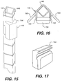
Figure 15 is a partial perspective view of a support
post and a wedge member in accordance with a third
embodiment of the present invention;
Figure 16 is a top view of a corner of a shelving
system in accordance with the third embodiment of the
present invention;
Figure 17 is a perspective view of a flipper in
accordance with the third embodiment of the present
invention;
Figure 18 is a partial perspective view of a support
post and wedge member in accordance with a modification
of the third embodiment of the present invention;
Figure 19 is a perspective view of a flipper in
accordance with the modified third embodiment of the
present invention;
Figure 20 is a partial perspective view of a flanged
support post and wedge member in accordance with a
fourth embodiment of the present invention;
Figure 21 is a top view of a corner portion of a
shelving system in accordance with the fourth
embodiment of the present invention;
Figure 22 is a perspective view of a flipper in
accordance with the fourth embodiment of the present
invention;
Figure 23 is a side elevational view of the support
assembly in accordance with the modified embodiment
shown in Figure 12B;
Figure 24 is a perspective view of a collar in
accordance with a fifth embodiment of the present
invention;
Figure 25 is a perspective view of a flipper in
accordance with the fifth embodiment of the present
invention;
Figure 26, is a bottom plan view of the flipper shown
in Figure 25;
Figure 27 is a rear elevational view of the flipper
shown in Figure 25;
Figure 28 is a cross-sectional view of the flipper
taken long lines I-I in Figure 27;
Figure 29 is a cross-sectional view of the flipper,
taken along lines II-II in Figure 27;
Figure 30 is a perspective view of a wedge in
accordance with the fifth embodiment of the invention;
Figure 31 is a side elevational view, partly in cross-section,
of the wedge shown in Figure 30;
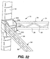
Figure 32 is a perspective view of the support assembly
in accordance with the fifth embodiment as viewed from
above a wire shelf frame; and
Figure 33 is a perspective view of the support assembly
in accordance with the fifth embodiment as viewed from
below the wire shelf frame.
Figure 34 is a perspective view of a collar in
accordance with a sixth embodiment of the present
invention;
Figure 35 is a to plan view of the collar in Figure 34;
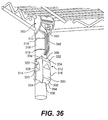
Figure 36 is a partial perspective view of a shelving
system in accordance with the sixth embodiment of the
present invention;
Figure 37 is a perspective view of an alternative wedge
assembly in accordance with the sixth embodiment of the
present invention;
Figure 38 is a side elevational view of a wedge member
in accordance with the sixth embodiment of the present
invention;
Figure 39 is a front elevational view of the wedge
member in accordance with the sixth embodiment of the
present invention;
Figure 40 is a top plan view of the wedge member in
accordance with the sixth embodiment of the present
invention;
Figure 41 is a top plan view, in section, of a collar
and a sleeve in accordance with the sixth embodiment of
the present invention;
Figure 42 is a top view, in section, of a collar and a
modified sleeve in accordance with the sixth embodiment
of the present invention;
Figure 43 is a perspective view of the corner assembly
in accordance with the sixth embodiment of the present
invention with the wedge assembly out of alignment; and
Figure 44 is a perspective view of the corner assembly
in accordance with the sixth embodiment of the present
invention also with the wedge assembly out of
alignment.
DESCRIPTION OF THE PREFERRED EMBODIMENTS
For purposes of explanation only, and to illustrate in
part how the present invention may be adapted easily to
conventional shelving technology, the support assembly
of the present invention will be described below in use
with a knockdown shelving system. The shelving system
generally includes a plurality of support posts, e.g.,
four, arranged to support one or more shelves at corner
assemblies thereof. Of course, the support assembly of
the present invention can be used in various types of
support systems, e.g., cabinets, closets, etc., with a
shelving system being only one example thereof.
Moreover, the support assembly can be used in
conjunction with many shelf embodiments and is not
limited to use with a corner of a shelf or, for that
matter, a corner of any supported member. In the
examples given below, the support assembly is
structurally associated with a wire shelf frame
designed to be fitted with plastic shelf mats.
However, the support assembly of the present invention
will be readily adaptable to many other shelf
embodiments including, but not limited to, a wire shelf
or a solid sheet metal shelf.
Figure 1 illustrates one corner of a shelving system
utilizing the support assembly in accordance with the
present invention. In this figure, a wire shelf frame
10 is positioned on an elongated support post 12 by a
corner support assembly 14.
Generally speaking, the corner support assembly 14 is
comprised of a collar 16 and a locking mechanism, or
flipper, 18 rotatably mounted to the collar. In this
view, the flipper is shown in its unlocked position.
The corner support assembly is secured between an end
outer rail 24 and a side outer rail 24' which form part
of the shelf frame 10. A tapered wedge member 20 is
positioned on the post where the shelf frame is to be
secured. With the flipper in the closed position, the
wedge member is compressed against the support post 12,
and the corner support assembly 14 surrounds the
support post and wedge member like a sleeve and is
seated thereon to support the shelf frame with a
wedging force.
Although Figure 1 is a partial view showing only one
corner of the shelving system, it will be understood
that the shelving system will normally include a
plurality of support posts 12 corresponding in number
to the number of corner support assemblies 14 in the
shelf frame 10. In a typical shelving system, one or
more rectangularly-shaped shelf frames will have a
corner support assembly in each of four corners.
In this embodiment, the wire shelf frame 10 is part of
a modular shelf that is formed by securing the outer
rails 24 and 24' to the corner support assemblies 14 by
conventional means such as welding. In a rectangular
shelf configuration, for example, two end outer rails
24 and two side outer rails 24' will be secured between
four corner support assemblies to comprise the wire
shelf frame. As illustrated in Figure 1, each outer
rail includes a top rail 26, a bottom rail 28 and a
snake-like rail 30 secured between the top and bottom
rails for stability. One or more transverse rails
(unshown) can be secured between parallel outer rails
for additional support and to increase the load-bearing
capacity of the shelf.
The preferred material for the collar 16 and the outer
rails 24 and 24' is metal, most preferably cold rolled
steel or stainless steel. These compositions are
relatively light weight, provide high structural
rigidity, and are inexpensive to manufacture by known
metal forming methods. Further, stainless steel is
resistant to corrosion and easily cleaned, so that it
may be utilized in many sanitary applications,
including food service applications.
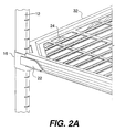
With reference to Figure 2A, the wire shelf frame
supports one or more removable shelf mats 32 to
complete the modular shelf. The shelf mats are
preferably made of a polymer material and can be snap-fit
or otherwise friction fit to the wire shelf frame.
This allows the shelf mats to be easily removed and
cleaned, if desired. Figure 2A also illustrates
shields 22 that can be snap-fit onto the shelf frame at
one or both ends of the side outer rail 24' to provide
an aesthetically pleasing, finished look. The vertical
edges of the shelf mats 32 at the corners are cut away
to accommodate the shields 22. The shields are
preferably used only on the side outer rails 24', which
are normally longer than the end outer rails 24.
Figure 2B is a perspective view of the shelving system
looking at one end of the shelf, which is not provided
with the shield.
An isolated view of the collar 16 is provided in Figure
3. The collar includes a cylindrical shaft 34,
preferably non-rotatable, secured between two lateral
sides 36 for rotatably supporting the flipper 18. In
accordance with the present invention, a rear section
of the collar 16 joining, or connecting, the two
lateral sides is contoured to fit the outward-facing
shape of the post 12. In this embodiment, the post has
a generally triangular cross-section as discussed in
detail below. The rear side is thus shaped to have a
straight portion 35 angled from each lateral side and
joined by a rounded apex 37.
Figure 4 illustrates the flipper 18 in accordance with
a first embodiment of the subject invention. The
flipper, which is preferably integrally formed, has an
upper end 41 and lower end 43. Further, the top end
has a flat portion 47 and a rounded portion 49, with
the rounded portion defining part of an open
cylindrical cavity 40 for receiving and containing the
shaft 34 of the collar 16. The lower end includes a
preferably flat manipulating portion 42 for grasping by
the user. A rear face 44 of the flipper, which extends
at an angle from the flat portion 47 and cannot be seen
in Figure 4, is shaped to complement the shape of the
wedge member 20, which in this embodiment is
substantially flat. The flipper is mounted on the
collar to rotate about a longitudinal axis of the
shaft. The preferred material for the flipper is a
rigid molded plastic such as, for example, reinforced
nylon.
While in this embodiment the cylindrical cavity 40 and
shaft 34 interface to rotatably support the flipper on
the collar, other means for rotatably supporting the
flipper could be provided without departing from the
scope of the invention. For example, the flipper could
have rounded beads on either end that would sit in
complementary-shaped indents on the collar, or
conversely, the collar could have the rounded beads
which mate with indents on opposite ends of the
flipper.
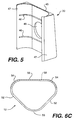
Figure 5 shows a wedge member 20 designed to clip onto
an interior face of the support post 12. The wedge
member includes a front portion 45 flanked by two
contoured lips 47 for clipping, or snap-fitting, the
wedge member onto the support post. In addition,
detent means such as internal beads, or ribs, 46 are
provided on the internal surface of the wedge member
and are spaced at intervals corresponding to the
spacing of grooves on the support post.
The configuration of the internal beads is designed to
mate with the configuration of the grooves in the
support post. Although two internal beads are shown in
the preferred embodiment, the wedge member may comprise
one or more internal beads. Further, the number, size
and shape of the internal beads may be varied for a
number of reasons including, for example, the size of
the wedge member 20, the size of the spacing of the
grooves in the support posts, and the shelving
application. The internal beads provide vertical
support when they are seated in the grooves of a
support post. To further secure the wedge member on
the support posts, additional vertical support is
provided by a wedge action as discussed below. It will
therefore be appreciated that the wedge member 20 may
be clipped on to the support posts at any incremented
height, and further may be translated up and down to
any other incremented height.
A cut-out 48 can be provided in the front portion 45 to
view optional numbers on the support post for
vertically aligning the wedge member with wedge members
on other support posts.
The outer surface of the front portion is substantially
flat in this embodiment to correspond to the
substantially flat rear face 44 of the flipper.
Although not readily recognizable in Figure 5, the
front portion is also slightly tapered from its upper
end to its lower end, such that the lower end is wider
and extends toward an interior of the shelving system.
In the preferred embodiment, the taper is shallow to
maximize rigidity and minimize the thickness of the
wedge member. For example, the taper is of the order
of 4°. A better view of the tapered shape of the wedge
member is provided in Figure 7A, which will be
discussed below.
With the tapered shape of the wedge member, an inwardly
directed force is created by the weight of the shelf
assembly to provide a wedging action between the corner
support assembly and the wedge member. The preferred
material for the wedge member is a molded plastic, such
as reinforced nylon. Such a molded plastic wedge
member can be easily clipped on to and off of the
support post. However, other materials which provide
the desired characteristics may be used.
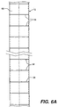
A vertical support post 12 in accordance with this
embodiment of the invention is shown in Figures 6A, 6B
and 6C. As best seen in Figure 6C, the support post 12
has a generally right equilateral triangular cross-section,
which can also be described as a trilobal
cross-section. A right-angled apex 50 and two flat
exterior sides 52 face the exterior of the shelving
system, and interior angled apexes 54 and an interior
side 56 of the support post face the interior of the
shelving assembly. Accordingly, as explained in detail
in U.S. Patent No. 4,811,670, which is herein
incorporated by reference, the triangular geometry of
the support post provides multi-directional stability,
particularly in the directions of critical stress
forces, i.e., in a direction parallel to the edges of
the shelf.
The support post includes a plurality of horizontal
grooves 58 that are preferably, but not necessarily,
evenly spaced in the longitudinal direction of the
post. In Figures 6A through 6C, the grooves are shown
to extend entirely across the interior side 56 of the
post and partially across the apexes 54 of the post.
Of course, grooves of different lengths could be
provided on the support post. The grooves receive the
internal beads 46 of the sleeve. As will be
appreciated, other comparable detent means for
positioning the wedge member to the support post, such
as detent tabs and detent steps as disclosed in U.S.
Patent No. 4,811,670, could be used without departing
from the scope of the present invention.
Although unshown in the drawings, the top end of each
support post 12 can be fitted with an end cap and the
bottom end with a caster, a vertically-adjustable foot,
an end cap, etc. As one example, the bottom end of the
support post can be fitted with a stem receptacle for
threadably receiving a leveling leg.
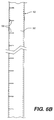
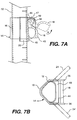
Figures 7A and 7B illustrate how the collar support
assembly 14 is secured to the support post 12. For the
sake of simplicity, the outer rails 24 and 24' have
been deleted in Figure 7A but are shown to be secured
to the lateral sides 36 of the collar 16 in Figure 7B.
When the wedge member 20 is mounted on the support post
12 at the desired height, the corner support assembly
14 is positioned over the wedge member and the support
post. In this regard, the collar 16 and flipper 18
together form a sleeve that fits over the wedge member
and the support post. When the flipper 18 is in the
closed, or locked, position as shown in solid lines in
Figure 7A, the rear face 44 of the flipper directs an
inward radial compression force against the wedge
member 20, in which the front portion 45 is cross-hatched
for clarity. In addition, the tapered shape of
the wedge creates a wedge action between the wedge
member and the flipper for supporting the shelf
assembly. It will be appreciated that the greater the
weight on the shelf, the greater the downward force and
thus the greater the wedging force.
Figure 7A will also be referred to in discussing two
salient features of the present invention. The first
feature relates to the ability of the flipper to easily
and quickly release the wedging action between the
corner support assembly and the wedge member. This
frees the shelf to slide up or down the support posts.
To release the wedging action, the closed flipper 18 is
rotated in the counter-clockwise direction of arrow a
to its unlocked position as represented by the dashed
lines. By pivoting the flipper about the shaft 38 in
this manner, the compression force between the flipper
18 and the wedge member is released. Actuation of the
flipper by the user thus allows for quick and reliable
releasing of the wedging action.
Another salient feature of the invention is directed to
the ability of the flipper to allow the corner support
assembly to slide over the support post and mounted
wedge member (or members). At rest, the flipper 18
normally hangs, by gravity, in substantially the same
position shown in solid lines in Figure 7A, i.e., with
the lower end 43 directed downwardly. Now, with the
flipper in this position and the corner support
assembly disposed below a wedge member mounted on the
support post, when the shelf is raised toward the wedge
member the lower (and wider) end of the wedge member
will initially contact the flat portion 47 of the upper
end of the flipper, causing it to rotate counter-clockwise
about the shaft 34 in the direction of arrow
a. This action raises the flipper toward its unlocked
position, whereby the rounded portion 49 of the upper
end is substantially opposite the wedge member. As the
flipper is biased toward its unlocked position, the
contour of the upper end allows the flipper to pass
completely over the wedge member.
The ability of the flipper to be rotated automatically
by the wedge member allows the support assembly to be
easily raised up the support post. As will be
appreciated, when the support assembly is raised over a
series of wedge members spaced apart on the support
post, the flipper will rotate automatically as
described above as it passes over each wedge member
and, as it clears the wedge member, rotate in the
opposite direction back to its at-rest position.
However, this action of the flipper takes place in only
one direction, i.e., raising of the support assembly 14
relative to the support post, and in that sense can be
described as a ratchet-like movement. When the support
assembly slides along the support post in the opposite
direction, i.e., downward toward a mounted wedge
member, the rear face 44 of the flipper mates with the
front portion 45 of the wedge member and creates a
wedging action. Of course, if the flipper is held in
its raised, or unlocked position, the flipper will
clear the wedge member and the support assembly can
slide downward over the support post and mounted wedge
member(s).
The ability of the corner support assembly to translate
relative to wedge member mounted on the support post
and slide completely thereover enables both the
assembly of a shelving system and an adjustment of the
height of the shelves to be accomplished with ease. To
adjust the height of an individual shelf, for example,
a second set of wedge members can be clipped on to the
support posts at the desired new height. The flippers
at the corner support assemblies are then rotated to
the unlocked position, releasing the compression force
applied to the wedge members by the flippers and
allowing the shelf to be raised or lowered. To raise
the height of the shelf, the shelf is raised along the
support posts to allow the flippers to pass over the
second set of wedge members in the manner described
above. Once the flippers clear the wedge members (such
that the flipper can rotate back to its at-rest
position), the shelf can be lowered, whereby the
flippers will seat on their respective wedge members to
create the desired wedging force. The first set of
wedge members can then be removed from the support
posts if desired.
It will be appreciated that with this arrangement that
allows the flippers to freely rotate, the flippers
"self-regulate" themselves as they return to the at-rest
position to match the slope of the wedge member.
The flippers thus automatically come to rest against a
respective wedge member regardless of the slope of the
wedge member to create the necessary wedging force.
To assemble a shelving system with a plurality of
shelves utilizing the corner support assembly of the
present invention, the shelves can be stacked on the
floor one atop the other. One set of wedge members for
each shelf is positioned on the support posts at the
desired shelf heights, and then the support posts are
inserted in the aligned corner support assemblies of
the shelves. Each shelf can then be raised, one-by-one,
over the sets of wedge members provided for lower
shelves and then over its designated set of wedge
members positioned at the desired height. As the shelf
passes over the designated wedge members, it is lowered
back thereon to allow the flippers, which fall back to
the at-rest position once the wedge members are
cleared, to engage and seat against the wedge members
to create a wedging force for supporting the shelf.
This "bottom up" assembly allows the shelving system to
be put together quickly and easily.
This static system of supporting the shelves, i.e.,
securing the shelves directly to the support posts,
allows for significant load-bearing capacity while
providing an easy to assemble and easy to adjust
support system.
With respect to the shields 22 which may be fitted to
the shelf assembly, isolated front and rear views of a
left-side shield 22 are provided in Figures 8A and 8B,
respectively. The shield is preferably formed of a
molded plastic having the resiliency necessary to be
snap-fit over the outer rails. In Figure 8A, the
shield 22 is shown to have a substantially flat front
face 60 and upper and lower rounded forms, 62 and 64,
for snap-fitting onto the outer rails 24'. The front
face is also defined by one vertical edge 66 and one
angled edge 68. As better seen in Figure 8B, the upper
and lower forms have a substantially semi-circular
cross-section and sufficient length to define an
extended cylindrical cavity. When in position, the
upper form 62 snap-fits over the top rail 26 and the
lower form 64 snap-fits over the bottom rail 28.
Although unshown in the drawing, a right-hand shield is
shaped in substantially the same way as the left-hand
shield, except that the vertical edge and the angled
edge are reversed.
While the support system of the present invention has
been described above in use with substantially
triangular-shaped support posts, support posts of other
shapes can be used without departing from the scope of
the invention. It will be appreciated that the
underlying principals of the invention can be used to
provide a collar that is contoured to fit around a
support post of many shapes and fitted with a rotatable
flipper also contoured to complement the outer surface
of a wedge member secured to the support post. The
wedge member, as well, can be readily adapted to fit
support posts of various shapes. The second, third and
fourth embodiments described below will better
illustrate the ability of the support system of the
present invention to be used with different types of
support posts.
The second embodiment illustrated in Figures 9 through
11 shows a support system of the present invention in
use with a cylindrical support post. The cylindrical
post 110 includes annular grooves 112 for receiving and
positioning a wedge member 114 in substantially the
same manner described above in the first embodiment,
i.e., by using detent means comprised of the annular
grooves 112 and complementary beads on the interior
surface of the wedge member 114. Of course, the
interior surface of the wedge member will be arcuate in
shape to complement the surface of the cylindrical
support post. The outer surface 116 of the wedge
member is substantially flat in Figure 9. As in the
first embodiment, the wedge member is tapered to
provide a slightly thicker, lower portion extending
toward the interior of the shelving system.
A collar 118 shown in Figure 10 has a different contour
than the collar disclosed in the first embodiment in
order to accommodate the shape of the support post. In
this second embodiment, an apex 122 of the collar is
more rounded to fit the cylindrical support post. Rear
sides 124 join the lateral sides 126 of the collar to
the apex. With this configuration, outer rails 128 of
the wire shelf frame are preferably, but not
necessarily, secured to the rear sides 124 of the
collar. A flipper 130 of substantially the same shape
and characteristics as in the first embodiment is
rotatably secured on a shaft 34 extending between the
lateral sides 126 of the collar. As in the first
embodiment, the rear face of the flipper is
substantially flat to complement to outer surface 116
of the wedge member.
In a first modified version of the second embodiment,
shown in Figures 12A, 13A and 14A, the outer surface of
the wedge member is altered. With reference to Figure
12A, a wedge member 132 having an arcuate outer surface
134 instead of a flat surface is employed. This
modified wedge member fits the support post like a
sleeve. The same or comparable detent means as
discussed above can be used to secure the wedge member
to the support post 110. An optional tab could extend
from one or both lateral edges of the wedge member for
additional support.
To accommodate for the rounded wedge member, rear sides
124' of the collar 116 are modified as shown in Figure
13A to fit the contour of the wedge member 132. In
this modification, the outer rails 128 are secured to
the lateral sides of the collar 126. In addition, the
rear face of the flipper 130 is cut out to form a semi-circular
cavity 138 for engaging the wedge member. The
modified complementary shapes of the wedge member and
the flipper create a wedging action sufficient to
support a shelf when the flipper closes to compress the
wedge member, which is still tapered in the manner
described above.
Another modification of the second embodiment is shown
in Figures 12B, 13B, 14B and 23. This modification
features a two-piece interlocking sleeve 135 of type
used in the SUPER ERECTA SHELF shelving system
described above. In that regard, the sleeve 135 is
comprised of first and second halves, 137 and 139,
respectively, that are snap-fit around the support post
and secured to each other by, for example, a tongue and
groove arrangement. The sleeve includes one or more
ribs (unshown) on its interior surface for engaging an
equal number of grooves on the support post. The
sleeve also has a frusto-conically-shaped outer
surface, which is widest at the bottom.
To accommodate for the frusto-conical shape of the
sleeve, a collar 123 will be provided with a rear
section 125 that slopes outwardly from top to bottom to
complement the slope of the sleeve. The slight slope
of the collar 123 is best seen in Figure 23. The top
view of the support assembly in Figure 13B also
illustrates this aspect of the invention. The flipper
130 is substantially identical to the flipper
illustrated in Figure 14A and discussed above, and
likewise creates a wedging force when closed to
compress the sleeve.
A third embodiment of the present invention is shown in
Figures 15 through 17. This embodiment features use of
a square support post 140 with outer peripheral grooves
142 equally-spaced in the longitudinal direction. In
keeping with the shape of the support post, an inner
surface of wedge member 144 has a right-angled V-shaped
cut-out for receiving a corner of the support post.
Other aspects of the wedge member are the same as in
embodiments 1 and 2 described above, i.e., the wedge
member includes detent means for mating with the
support post and has a tapered outer surface 145.
Figure 16 shows a collar 146 with a right-angled rear
side 148 to complement the outer corner of the support
post. Outer rails 150 of the shelf frame are
preferably secured to lateral sides 152 of the collar
in this embodiment. Substantially the same flipper 154
as disclosed in the first and second embodiments is
rotatably mounted on a shaft between the lateral sides
152 of the collar in the same manner described above.
The outer surface of the wedge member and the rear face
of the flipper are complementary-shaped to mate with
each other, and in the illustrated example are both
substantially flat.
In a modification of the third embodiment, tapered
wedge member 144' can be formed with a right-angled
outer surface as shown in Figure 18. To accommodate
for this modification, flipper member 154' has a right-angled
cut-out 156 in its rear face as shown in Figure
19 to complement the shape of the wedge member, which
is tapered as described above. The modified flipper is
thus able to compress the wedge member in the same
manner described above to create a wedging force for
supporting a shelf.
In the fourth embodiment, the support system of the
present invention is used in conjunction with a flanged
support post 160 as shown in Figure 20. The flanged
support post itself is the subject of U.S. application
Serial No. 08/426,674, and is formed to have an
interior post 162 with a plurality of radially
extending flanges 164 spaced equally about its
circumference. With reference to Figures 20 and 21,
each flange includes a first portion 166 extending
radially from the interior post and a second portion
168 transverse to the first portion and having an
arcuate outer periphery. Longitudinal slots 170 are
formed between each adjacent pair of flanges 164.
Lateral circumferential grooves 172 can also be formed
on each flange and evenly spaced in the longitudinal
direction.
A tapered wedge member 174 can be secured to the
support post by the same or comparable detent means
used to secure the wedge members in the above-described
embodiments. Alternatively, the wedge member could be
secured to the flanged support post by interacting with
the longitudinal slots 170. The collar 176 shown in
Figure 21 has a rounded back section 178 contoured to
fit around the circumference of the flanged support
post. As in the other embodiments, a flipper 180 is
rotatably secured between lateral sides 182 of the
collar for compressing the wedge member.
A fifth embodiment of present invention is shown in
various isolated views in Figures 24 through 31 and in
an assembled state in Figures 32 and 33. This
embodiment generally features modified versions of
several elements disclosed initially in connection with
the first embodiment of the invention. More
particularly, modifications of a collar and a flipper
(collectively a corner support assembly) and of a
tapered wedge member are disclosed below.
The modified elements are designed for use with a
triangular support post 12 as shown in Figures 6A
through 6C, as in the first disclosed embodiment. As
will be appreciated, however, the following
modifications are readily adapted to corner support
assemblies and wedges designed for use with support
posts of other shapes, including but not limited to the
shapes disclosed in the second, third and fourth
embodiments.
A collar 200 of the fifth embodiment is illustrated in
Figures 24 and 25. As in the first embodiment, the
collar includes a cylindrical shaft 202, preferably
non-rotatable, secured between two lateral sides 204
for rotatably supporting a flipper. A rear section of
the collar connecting the two lateral sides is
contoured to fit the outward facing shape of the
support post With the post having a generally
triangular cross-section in this embodiment as
discussed above, the rear section is thus shaped to
have straight portions 206 angled from each lateral
side and joined by a rounded apex 208.
In this embodiment, the shaft 202 is secured at
substantially the vertical center, or a middle portion,
of the collar as shown in Figure 24. In addition, a
top portion 210 of the collar has a larger radius than
the collar shown in Figure 3. For example, in one
embodiment the radius of the top portion 210 in Figure
24 is .875" and the radius of a lower portion 212 of
the collar is .250".
A flipper 214 in accordance with this embodiment is
shown in Figures 25 through 29. The perspective view
of Figure 25 shows the flipper 214 to include, at its
top end 216, a flat portion 218 and a rounded portion
220. In addition, a preferably flat transition portion
219 exists between the flat and rounded portions. An
open cylindrical cavity 222 receives and contains the
shaft 202 of the collar. As will be appreciated, the
top end 216 of the flipper is substantially the same as
the top end of the flipper disclosed in the first
embodiment
The primary difference of the flipper in this
embodiment is that its bottom end 224 is rounded
instead of flat like the flipper shown in Figure 4. As
best seen in Figures 25 and 26, the rounded bottom end
224 also includes a rounded bottom edge 226. As in the
first embodiment, the bottom edge is preferably
chamfered. The rounding of this portion of the flipper
provides a semi-circular cavity 228 in which the
fingers of the user can comfortably rest when opening
the flipper. Rounding the bottom end 224 also makes
the flipper less susceptible to being accidentally
opened by movement of articles on the shelf below.
As in the first embodiment, a rear face 229 of the
flipper is substantially flat to complement the shape
of the wedge member. As shown in Figures 27 and 29,
however, the rear face 228 can include pockets 230 to
aid in molding.
A wedge member 232 in this embodiment is substantially
the same wedge member shown in Figure 5, but with a
greater body length. As in the first embodiment, the
wedge member 232 in Figure 30 includes a front portion
234 flanked by two contoured lips 236 for clipping, or
snap-fitting, the wedge member onto the support post.
Internal beads, or ribs, 238 are provided on the
internal surface of the wedge member and are spaced at
intervals corresponding to the spacing of grooves on
the support post, as in the first embodiment.
The cross-sectional view of Figure 31 illustrates the
extra body length of the wedge member in this
embodiment. The extra body length a, in this example
.625", is added to the top portion of the wedge member
232, making its total length 2.625". As seen in this
figure, the extra body length a is not tapered as is
the remaining length b of the wedge member. As
illustrated, the lower end is wider than the upper end
so as to extend toward an interior end of the shelving
system. In this embodiment, the taper is of the order
of 4°.
As demonstrated in Figures 32 and 33, the collar, the
flipper and the wedge member of this embodiment work
together in the same manner disclosed in the first
embodiment to securely support a shelf wire frame 10 on
the support posts. In this embodiment, however, moving
the shaft 202 to the center, or middle portion, of the
collar serves to more evenly distribute the stress on
the top and bottom rails, 26 and 28, of the wire shelf
frame 10 where they are secured (such as by welding) to
the collar 200. With this arrangement, the shelf sits
a little higher up on the support assembly than in the
first embodiment, and the longer wedge makes it easier
to reduce or even eliminate the space between a corner
of a shelf mat and the support post, which can trap
dirt, food particles or other undesirable items.
A sixth embodiment of the present invention is shown in
Figures 34 through 44. This embodiment generally
features a modified collar and wedge member that
provide a 'self-aligning' feature as the shelf frame is
set in place. This feature allows for the wedge member
to be 'cammed' into alignment with the corner support
assembly by interaction with the collar. As will be
appreciated, the modified elements in this embodiment
will be most useful with a cylindrical support post of
the type shown in Figure 9 because of the relative
tendency of the wedge member to become misaligned on
such a support post.
An isolated view of a collar 300 of the sixth
embodiment is provided in Figures 34 and 35. As in the
previous embodiments, the collar includes a cylindrical
shaft 302, preferably non-rotatable, secured between
two lateral sides 304 for rotatably supporting a
flipper, or locking mechanism. A rear section 308 of
the collar connecting the two lateral sides is
contoured to fit a rounded sleeve which is discussed
below. In this embodiment, the lateral sides are
generally parallel to each other, and a cross-section
of the collar is generally U-shaped as best seen in
Figure 35.
The primary modification of the collar in this
embodiment is the shape of the corners, both top and
bottom, of the lateral sides 304. As shown in Figure
34, corners 310 of the lateral sides are shaped, e.g.,
rounded, to provide surfaces engagable with a wedge
assembly as discussed in detail below. In a preferred
example, the entire outer edge of the collar is arcuate
to provide both the top and bottom corners with rounded
portions.
The cylindrical shaft 302 is preferably located
approximately at a middle portion of the collar 300 as
discussed above in the fifth embodiment. However, the
shaft can be placed at other locations on the collar
without departing from the scope of the invention.
The sixth embodiment also features a two-piece wedge
assembly 312 instead of the wedge member discussed in
the earlier embodiments. As seen in Figure 36, the
member assembly is formed of a sleeve 314 and a wedge
316 that are snap-fit or otherwise joined together
about a support post 318. In this embodiment the wedge
assembly employs a tongue 320 and groove 322
arrangement. The two-piece assembly allows the wedge
to be easily detached and moved along the support post
to the desired position. Although not seen in Figure
36, both the sleeve and the wedge preferably have at
least one internal bead, or ridge, for engaging
horizontal grooves 319 in the support post. As shown
in the figure, finger grip cutouts 328 can be provided
in the tongue 320 for ease of removing the sleeve from
the post.
As an alternative to the tongue and groove arrangement
shown in Figure 36, the sleeve and the wedge can fit
together by other comparable means. For example,
Figure 37 shows the sleeve 314 and wedge 316 connected
by a hinge 329. In this arrangement the hinge is
integral with the sleeve and has a pin 331 which
rotatably fits in a slot 333 in the wedge. Of course,
other types of hinges, e.g., a living hinge, can
alternatively be used.
The shape of the wedge 316, in combination with the
rounded corners of the collar, provides the self-aligning
feature of this embodiment. As seen in
Figures 36, as well as in Figures 37 through 40, the
wedge has a planar face 330 that tapers from its upper
end to lower end, as in the other embodiments, such
that the lower end is wider and extends toward an
interior of the shelving system. In this embodiment,
opposite ends 332 of the face are arcuate, or rounded,
and shaped to form inwardly directed ridges 334. The
sides of the wedge 316 also taper toward the support
post at opposite ends to help form the ridges. As seen
in the figures, the two ridges 334 at each end of the
wedge are curved toward each other and an arcuate cut-out,
or scallop, 336 is formed therebetween. Aligning
numbers on the support post can be seen within the
scallop, as shown in Figure 36, when the wedge is
preferably positioned.
As an alternative to the two-piece wedge assembly, a
one-piece wedge assembly without the sleeve can also be
used. In this alternative, a wedge would be formed
with the same contour surfaces and ridges disclosed
above, but the sides would extend further around the
support post to secure the wedge without the need for a
sleeve. Without the sleeve, the interior contour of
the collar would of course be modified as necessary to
fit around the support post and the wedge.
A flipper 340 shown in Figure 36 has a handle 342 which
is longer and narrower than in the other embodiments.
The elongated shape of the handle provides more
leverage and requires less pull force to open. In all
other primary aspects, the flipper 340 has the same
shapes and characteristics as disclosed in the other
embodiments and is rotatably secured about cylindrical
shaft 302 on the collar 300. Thus, it will be
appreciated that the flippers disclosed in the other
embodiments could also be used in this embodiment and
vice-versa, i.e., the flipper 340 could be used in the
other embodiments.
It will be appreciated that the flipper discussed in
this embodiment, as well as the other embodiments,
serves as a locking mechanism and is actuable (e.g., by
rotating) between first and second positions as
described above. As an alternative to such a flipper,
however, a non-rotatable securing member can be
provided . The securing member will function
essentially in the same manner as the flipper, i.e., to
press-fit against the wedge assembly, and can be
structurally supported by the collar or formed as part
of the collar.
Figure 41 is a top view, in section, of the collar 300
and the sleeve 314 in the sixth embodiment. In this
figure, the outside diameter of the sleeve is
substantially the same as the inside diameter of the
collar, thus making for an ideal fit between these
components. However, if the outside or inside
diameters, i.e., the mating surfaces, do not match,
potential problems such as movement of the sleeve
within the collar, e.g., rocking, or reduced overall
stiffness of the shelving system can exist.
To avoid such potential problems, Figure 42 shows a
sleeve that is modified to have a flat face 344,
preferably at its circumferential midpoint and
extending along its entire vertical length. The flat
face provides two distinct contact points 346 for
contacting the collar and preventing, or at least
significantly reducing, movement between the sleeve and
the collar that can occur when the mating surfaces do
not match. The sleeve is otherwise the same as
disclosed above.
The advantages provided by the elements disclosed in
the sixth embodiment will be readily appreciated by the
examples provided below.
In Figure 43, the corner support assembly 350 is ready
to be lowered onto the wedge assembly 312. However, in
this view the wedge 316 is slightly out of alignment
(too far to the left). As the corner assembly is
lowered, the lower rounded corner 310 of the collar 300
will engage the ridge 334 on the wedge 316 and force,
or cam, the wedge assembly to turn in a counter-clockwise
direction about its longitudinal axis and the
support post until it is in alignment with the collar.
As will be appreciated, the surfaces of the collar
(i.e., rounded corner 310) and the camming surfaces of
the wedge (i.e., ridge 334) are shaped so as to
disengage from each other once the wedge is properly
aligned. Such proper alignment is achieved when the
face 310 of the wedge is in generally parallel
alignment with the flipper 340 or, in other words, when
the collar can slide over the wedge.
In Figure 44, the wedge assembly is aligned too far to
the right. As the corner assembly is lowered, the
lower rounded corner 310 of the collar 300 will engage
the ridge 334 on the wedge and turn the wedge assembly
in a clockwise direction about the support post to its
properly aligned position.
The ridges 334 on the lower end of the wedge allow for
alignment of the wedge assembly when the corner
assembly is being raised such as, for example, during
'bottom-up' assembly of the shelving system as
described earlier. When the shelf frame 301 is being
raised, top rounded corners of the collar will engage
the lower ridges 334 to adjust the alignment of the
wedge assembly if necessary.
As the foregoing description of the preferred
embodiments describes, an advantage of the present
invention is that it allows a user to quickly and
easily change the height of the supported item, e.g., a
shelf, to accommodate a variety of shelving
applications. Moreover, since the support system
allows the shelf frame to slide over the wedge member
mounted on the support posts, height adjustment is easy
and can be done without tools or without having to
remove adjacent shelves. The shelf-aligning feature of
the invention further eases assembly and/or adjustment
of the shelving system.
Although specific embodiments of the present invention
have been described above in detail, it will be
understood that this description is merely for purposes
of illustration. Various modifications of and
equivalent structures corresponding to the disclosed
aspects of the preferred embodiments in addition to
those described above may be made by those skilled in
the art without departing from the spirit of the
present invention which is defined in the following
claims, the scope of which is to be accorded the
broadest interpretation so as to encompass such
modifications and equivalent structures.