EP0891786A2 - Medical electrical lead containing a magnetic fluid - Google Patents
Medical electrical lead containing a magnetic fluid Download PDFInfo
- Publication number
- EP0891786A2 EP0891786A2 EP98305415A EP98305415A EP0891786A2 EP 0891786 A2 EP0891786 A2 EP 0891786A2 EP 98305415 A EP98305415 A EP 98305415A EP 98305415 A EP98305415 A EP 98305415A EP 0891786 A2 EP0891786 A2 EP 0891786A2
- Authority
- EP
- European Patent Office
- Prior art keywords
- lead
- lead body
- mrf
- cavity
- medical electrical
- Prior art date
- Legal status (The legal status is an assumption and is not a legal conclusion. Google has not performed a legal analysis and makes no representation as to the accuracy of the status listed.)
- Withdrawn
Links
Images

Classifications
-
- A—HUMAN NECESSITIES
- A61—MEDICAL OR VETERINARY SCIENCE; HYGIENE
- A61N—ELECTROTHERAPY; MAGNETOTHERAPY; RADIATION THERAPY; ULTRASOUND THERAPY
- A61N1/00—Electrotherapy; Circuits therefor
- A61N1/02—Details
- A61N1/04—Electrodes
- A61N1/05—Electrodes for implantation or insertion into the body, e.g. heart electrode
- A61N1/056—Transvascular endocardial electrode systems
- A61N2001/0585—Coronary sinus electrodes
Definitions
- the present invention relates to medical electrical leads.
- One type of commonly used implantable lead is an endocardial pacing lead.
- Endocardial pacing leads are attached at their proximal end to an implantable pulse generator and at their distal end to the endocardium of a cardiac chamber.
- the distal end of an endocardial lead may engage the endocardium by either an active fixation mechanism or a passive fixation mechanism.
- Active fixation mechanisms use a structure, such as helix or hook, to physically engage into or actively affix themselves onto the heart.
- Passive fixation mechanisms such as a tine assembly, lodge or passively fix themselves to the heart.
- the atrium unlike the ventricle, is relatively smooth in its interior.
- passive fixation systems such as tines, are not able to reliably engage into structures along the interior portion of the atrium.
- the atrial chamber moreover, is also generally thin. This means that there is not a large, meaty, portion of tissue available for an active fixation device to engage with.
- U.S. Patent No. 4,454,888 provided a J-shaped atrial lead in which the pre-bent J-portion of the lead was formed using a separate metallic strip. During chronic use, however, this metallic strip often dislodged or separated from the lead body upon which it presented a sharpened metal barb to the tissues. Not surprisingly, this unfortunately had catastrophic consequences for the patients.
- Another approach to electrode placement within the atrium may be seen in the patent of Riestriena U.S. Patent No. 4,401,126 which discloses a lead body having various loops and stiffness of the lead body in the atrium.
- This design has several drawbacks, including it being difficult to implant and properly position the loop containing the electrodes, as well as the lead body being permanently stiff in the area of the atrium. Permanent stiffness of the lead body in the area of the atrium may have several drawbacks.
- the stiffened lead body may not permit the atrium to fully contract when such a lead is implanted. This can cause a hemodynamic insufficiency or impair cardiac output.
- the heart muscle may develop, in response to the object, so as to contract with greater force in the area. This increased area of heart tissue, often called cardiomyopathy, may have untoward effects on the conduction pathways, also contributing to diminished cardiac output.
- the present invention concerns a medical electrical lead which features a portion of the lead body which may be made temporarily stiff.
- a medical electrical lead comprising: a lead body, the lead body having a first portion and a second portion, the lead body further having an insulative sheath and a conductor, the insulative sheath having a first end and a second end, the conductor positioned within the insulative sheath and extending between the first end and the second end; means for temporarily making a first portion of the lead body more stiff by exposing the first portion to a magnetic field; and an electrode positioned near the second end, the electrode coupled to the conductor.
- a medical electrical lead comprising: a lead body, the lead body having a first portion and a second portion, the lead body further having an insulative sheath and a conductor, the insulative sheath having a first end and a second end, the conductor positioned within the insulative sheath and extending between the first end and the second end; a stylet positioned extending from a first end of the lead body into an interior portion of the lead body; means for temporarily permitting the longitudinal transfer of force between the stylet and the lead body by exposing the lead body to a magnetic field.
- the lead preferred is designed for implantation into a body and would include electrodes for both the ventricle and the atrium.
- the temporarily stiff portion may be located along the lead body in the area strictly within the atrium or may also include portions of the lead body implanted in the ventricle or even in the superior vena cava.
- the atrial portion further includes one or more electrodes.
- the temporarily stiff portion is formed through the use of a cavity in the lead body filled with magnet-rheologic fluid (hereinafter called "MRF").
- MRF magnet-rheologic fluid
- the lead body moreover, in this area will also be attracted to the magnet thereby causing the lead body in that portion to migrate towards the magnet.
- the MRF filled cavity may either be cylindrical in cross-section or have other cross-sections, such as a semi-circle.
- the temporarily stiff portion may be located anywhere along the lead body between the proximal and distal ends. In the preferred embodiment the temporarily stiff portion is located between approximately 0 and 20 cm from the lead distal end and is between approximately 2 cm and 20 cm in total length. In an additional embodiment the lead is disclosed for coronary sinus placement. Finally, a further embodiment is shown which features MRF for the transfer of force from a stylet to the lead.
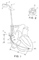
- FIG. 1 is a view of a system featuring a lead according to the present invention.
- FIG. 2 is a cross-sectional view of the lead body shown in FIG. 1.
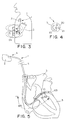
- FIG. 3 is a side view showing a lead implanted within a patient and a magnet used to stiffen the lead body.
- FIG. 4 is an alternative embodiment of the lead shown in FIG. 1.
- FIG. 5 is an alternative embodiment of a lead which is designed for implantation in the coronary sinus.
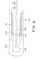
- FIG. 6 is an alternative embodiment of a lead.
- FIG. 7 is a alternative embodiment of the lead shown in FIG. 1.
- FIG. 8 is a cross-sectional view of the lead body shown in FIG. 7.
- FIGS. are not necessarily to scale.
- the present invention is not limited to use only in introducing atrial or ventricular pacing leads, and may be employed in introducing many of various types of therapeutic or diagnostic devices including transvenous leads intended to be disposed at various places within the patient, including, for example, leads intended to be disposed within the patient's coronary sinus, as well as various other types of electrical leads, including nerve, muscle or defibrillation leads. It is to be further understood, moreover, the present invention may be employed in introducing many of various types of therapeutic or diagnostic catheters and is not limited only to the introduction of electrical leads. For purposes of illustration only, however, the present invention is below described in the context of the introduction of endocardial pacing leads. The term "lead”, however, is used in the broadest possible manner and should be read to include any elongate medical device.
- FIG. 1 is a view of a lead of the present invention.
- lead 1 is used to couple an implantable pulse generator 2 to a heart 3.
- Implantable pulse generator as used herein refers to any device which provides electrical stimulation therapy to a body tissue or organ and is not intended to merely be limited to a so-called pacemaker. In the preferred embodiment, however, implantable pulse generator comprises any dual chamber model selected from the Medtronic Thera® series of pacemakers.
- lead 1 has essentially three portions, a connector pin assembly 4, a lead body 5 and an electrode portion 6.
- Connector pin assembly 4 is of any standard design suitable for use in coupling the lead to an implantable medical device such as those connectors conforming to the IS-1 standard, to name an example.
- Lead body 5 is constructed from an insulative sheath 10 and one or more conductors 11, as best seen in FIG. 2. Electrode portion 6 of the lead body features a pair of electrodes 61, 62 spaced apart a distance 8.6 mm. Further details concerning atrial electrodes as well as the tip electrode 63 which may be used can be found in the U.S. Patent No.5,628,778 "Single Pass Medical Electrical Lead" of Kruse et al. As discussed in more detail below, the electrode portion of the lead body features one or more cavities containing MRF fluid. Thus, when the MRF is made solid through the presence of a magnetic field, the corresponding section of the lead body will become stiffer.
- the MRF 15 extends for a length 81 at a distance 82 from the distal end of the lead. In the preferred embodiment both length and distance are approximately 8 cm. Of course, each dimension may vary, and it is conceived the cavity containing MRF may extend for a length of approximately 2-20 cm at a distance of approximately 0-20 cm from the distal end of the lead. Moreover, although a single MRF cavity is illustrated, multiple cavities containing MRF may also be implemented, as shown below.
- FIG. 2 is a cross-section of the lead body shown in FIG. 1.
- the lead body is constructed from an insulated polymer sheath 10 and one or more conductors 11.
- the sheath is silicone and has four cylindrical cavities running at least within a portion of the length of the sheath. Positioned along the length of three such cavities are the conductors.
- conductors are coiled multi-filar conductors of a biocompatible alloy such as MP35N. Although shown as coiled conductors it should be understood other devices of conductors may also be used such as bundle stranded wires.
- the coiled design of the conductors as well as their cross-sections may also be varied if desired.
- MRF is a material which normally exists in a liquid form, but, in the presence of a sufficiently intense magnetic field, will act as a solid.
- the particular intensity necessary to achieve the desired transformation of the MRF from liquid to solid depends upon the particular MRF used.
- the MRF is model MRF 32 LD, a silicone oil based MRF available from Lord Corporation, 405 Gregson Drive, Cary, North Carolina, U.S.A.
- FIG. 3 is a side view showing a lead according to the present invention implanted within a patient having a magnet placed in proximity to thereby cause the lead body to stiffen.
- the MRF solidifies when in the presence of a magnet 99.
- the lead according to the present invention features a portion of the lead body having MRF therein. When such a lead is placed in the presence of a magnetic field the MRF will solidify causing the lead body flex characteristics to thereby also solidify or stiffen. Through such a design, the lead body will be drawn against the heart wall in the direction shown thereby causing the electrodes to become in better contact with the heart tissue.
- the heart tissue will be aggravated by the temporarily stiff lead body thereby accelerating the growth of fibrotic tissue in this area.
- fibrotic tissue growth will act to fix or couple, through such tissue, the lead body, and thus the nearby electrodes, to the heart. Long term, this means the lead is better coupled to the previously uncoupleable atrial tissue.
- the lead body in this area will also be attracted to the magnet thereby causing the lead body in that portion to migrate towards the magnet and further assist in the optimal contact of the electrodes to the heart tissue.
- the magnetic field may be provided using either a conventional magnet or some sort of electromagnet, whichever is preferred.
- a conventional magnet or some sort of electromagnet, whichever is preferred.
- the particular intensity necessary to achieve the desired transformation of the MRF from liquid to solid depends upon the particular MRF used.
- a second magnet (not shown) may be provided in the vicinity of the pulse generator to prevent the lead body stiffening magnet resetting or tripping a reed switch in the pulse generator.
- FIG. 4 is a alternative embodiment of the lead shown in FIG. 1.
- the lead is entirely the same as that shown in FIG. 1 but for a varied cross-section of the lead body.
- the lead body is an insulative sheath 20 having a series of three lumens 21 being circular in cross-section with a fourth lumen 22 being semi-circular in cross-section.
- the flex characteristics of the lead body in the vicinity of the MRF may be changed.
- the lead body may be made to become more stiff due to the MRF as compared to a simple cylinder filled with MRF.
- the semi-cylindrical shape is shown, other shapes may be used, such as squares, ellipses, rectangles or any combination thereof.
- FIG. 5 is an alternative embodiment of a lead design for implantation in the coronary sinus.
- the lead body in this embodiment features an MRF portion which extends from the distal end of the lead for an amount preferably between 12-15 cm so that it extends, in a patient, from the SVC to the great vein.
- the distal portion of the lead body may be stiffened using a magnet to thereby increase the ease of insertion of the lead in the coronary sinus.
- the lead further features a distal type electrode as well as two ring electrodes of a design well known in the art.
- FIG. 6 is an alternative embodiment of a lead.
- MRF is used so as to enhance the ability of a stylet to control the end of the lead without necessitating any complex stylet lead interlocks.
- lead 100 is constructed in a typical fashion, featuring coiled conductor 101 and insulative sheath 102. Both sheath and conductor may be fabricated from any desired material, such as silicone and MP35 N respectively to name an example.
- distal cap assembly 105 Positioned on the distal end of lead is distal cap assembly 105.
- Distal cap assembly features a cavity filled with MRF 106.
- Distal cap assembly further features a valve 107 so as to maintain the MRF while in the fluid state within the cavity.
- the valve may be of any design such that a stylet 108 may be introduced therethrough and into the MRF.
- the shown valve comprises a annular flap of silicone having a hole therethrough.
- the stylet features a bulb at its distal end. The bulb increases the amount of friction between the MRF and the stylet once the MRF is made solid. This permits the stylet to be pulled in the direction 110 or pushed in the direction 111 so as to better enable the MRF and the stylet to manipulate the lead.
- the MRF is only solid within the presence of a sufficient magnetic field.
- the stylet may be easily removed from MRF 106.
- FIG. 7 is an alternative embodiment of the present invention.
- electrode portion 6 of lead body 5 features a pair of cavities 75, 76 containing MRF fluid.
- Cavity 75 extends for a length 85 of between approximately 1-10 cm with approximately 4 cm preferred.
- Cavity 76 extends for a length 86 of between approximately 1-10 cm with approximately 4 cm preferred.
- each cavity borders an electrode 61, 62 which function as a bipolar electrode for use in stimulating and sensing the heart.
- electrodes may be constructed in any suitable fashion known in the art. The electrodes are spaced apart a distance 8.6 mm. Further details concerning atrial electrodes which may be used can be found in the U.S. Patent No.5,628,778 "Single Pass Medical Electrical Lead" of Kruse et al.
- FIG. 8 is a cross sectional view across line 8-8 of the lead body shown in FIG. 7
- the MRF containing cavity 75 is rectangular in cross section. Although only one cavity is shown in this view, the other cavity 76 is also rectangular in shape.
- the conductors 90 used are fashioned from HBSW wire of MP35N.
Abstract
Description
Claims (10)
- A medical electrical lead (1) comprising:a lead body (5), the lead body having a first portion and a second portion, the lead body further having an insulative sheath (10) and a conductor (11), the insulative sheath having a first end and a second end, the conductor (11) positioned within the insulative sheath (10) and extending between the first end and the second end;means (15) for temporarily making a first portion of the lead body more stiff by exposing the first portion to a magnetic field; andan electrode (61, 62, 63) positioned near the second end, the electrode coupled to the conductor (11).
- A medical electrical lead according to claim 1 wherein the means for temporarily making a first portion of the lead body more stiff comprises a first cavity in the first portion of the lead body, the first cavity containing a first amount of MRF (15).
- A medical electrical lead according to claim 2 wherein the first cavity (15) is within the insulative sheath (10).
- A medical electrical lead according to claim 2 or 3 wherein the first cavity (15) comprises a cylindrical cavity.
- A medical electrical lead according to claim 2, 3 or 4 wherein the first cavity (15) is located approximately 8 cm from the distal tip of the lead.
- A medical electrical lead according to claim 2, 3, 4 or 5 wherein the first cavity (15) is approximately 8 cm long.
- A medical electrical lead according to any preceding claim, further comprising:means for temporarily making the first portion of the lead body more stiff by exposing the first portion to a first magnetic field.
- A medical electrical lead according to claim 7 wherein the means for temporarily making a second portion of the lead body more stiff comprises a second cavity in the second portion of the lead body, the second cavity containing MRF.
- A medical electrical lead (100) comprising:a lead body, the lead body having a first portion and a second portion, the lead body further having an insulative sheath (102) and a conductor (101), the insulative sheath having a first end and a second end, the conductor (101) positioned within the insulative sheath (102) and extending between the first end and the second end;a stylet (108) positioned extending from a first end of the lead body into an interior portion of the lead body;means (106) for temporarily permitting the longitudinal transfer of force between the stylet and the lead body by exposing the lead body to a magnetic field.
- A medical electrical lead according to claim 9 wherein the lead body has at least a first cavity (106) in the first portion, the first cavity containing a first amount of MRF.
Applications Claiming Priority (2)
| Application Number | Priority Date | Filing Date | Title |
|---|---|---|---|
| US08/896,096 US5800497A (en) | 1997-07-17 | 1997-07-17 | Medical electrical lead with temporarily stiff portion |
| US896096 | 1997-07-17 |
Publications (2)
| Publication Number | Publication Date |
|---|---|
| EP0891786A2 true EP0891786A2 (en) | 1999-01-20 |
| EP0891786A3 EP0891786A3 (en) | 1999-12-22 |
Family
ID=25405621
Family Applications (1)
| Application Number | Title | Priority Date | Filing Date |
|---|---|---|---|
| EP98305415A Withdrawn EP0891786A3 (en) | 1997-07-17 | 1998-07-08 | Medical electrical lead containing a magnetic fluid |
Country Status (2)
| Country | Link |
|---|---|
| US (1) | US5800497A (en) |
| EP (1) | EP0891786A3 (en) |
Cited By (6)
| Publication number | Priority date | Publication date | Assignee | Title |
|---|---|---|---|---|
| US8543207B2 (en) | 2004-12-17 | 2013-09-24 | Cardiac Pacemakers, Inc. | MRI operation modes for implantable medical devices |
| US8554335B2 (en) | 2007-12-06 | 2013-10-08 | Cardiac Pacemakers, Inc. | Method and apparatus for disconnecting the tip electrode during MRI |
| US8565874B2 (en) | 2009-12-08 | 2013-10-22 | Cardiac Pacemakers, Inc. | Implantable medical device with automatic tachycardia detection and control in MRI environments |
| US8897875B2 (en) | 2007-12-06 | 2014-11-25 | Cardiac Pacemakers, Inc. | Selectively connecting the tip electrode during therapy for MRI shielding |
| US8977356B2 (en) | 2009-02-19 | 2015-03-10 | Cardiac Pacemakers, Inc. | Systems and methods for providing arrhythmia therapy in MRI environments |
| US9561378B2 (en) | 2008-10-02 | 2017-02-07 | Cardiac Pacemakers, Inc. | Implantable medical device responsive to MRI induced capture threshold changes |
Families Citing this family (67)
| Publication number | Priority date | Publication date | Assignee | Title |
|---|---|---|---|---|
| US6634364B2 (en) | 2000-12-15 | 2003-10-21 | Cardiac Pacemakers, Inc. | Method of deploying a ventricular lead containing a hemostasis mechanism |
| US6240321B1 (en) | 1998-08-12 | 2001-05-29 | Cardiac Pacemakers, Inc. | Expandable seal for use with medical device and system |
| US6385472B1 (en) * | 1999-09-10 | 2002-05-07 | Stereotaxis, Inc. | Magnetically navigable telescoping catheter and method of navigating telescoping catheter |
| US6408213B1 (en) * | 1999-09-29 | 2002-06-18 | Cardiac Pacemakers, Inc. | Low profile, ventricular, transvenous, epicardial defibrillation lead |
| US6301507B1 (en) | 2000-01-20 | 2001-10-09 | Medtronic, Inc | Medical electrical lead having pre-formed atrial section |
| US6817364B2 (en) * | 2000-07-24 | 2004-11-16 | Stereotaxis, Inc. | Magnetically navigated pacing leads, and methods for delivering medical devices |
| US6584362B1 (en) | 2000-08-30 | 2003-06-24 | Cardiac Pacemakers, Inc. | Leads for pacing and/or sensing the heart from within the coronary veins |
| US6695793B2 (en) | 2001-07-31 | 2004-02-24 | Cardiac Pacemakers, Inc. | Guide catheter for placing cardiac lead |
| US6763270B1 (en) | 2001-08-07 | 2004-07-13 | Pacesetter, Inc. | Lead extraction mechanism for active fixation leads |
| US20030065373A1 (en) * | 2001-10-02 | 2003-04-03 | Lovett Eric G. | Medical device having rheometric materials and method therefor |
| US7072703B2 (en) * | 2002-12-31 | 2006-07-04 | Cardiac Pacemakers, Inc. | Medical device with force monitoring features and method therefor |
| US7218970B2 (en) * | 2003-06-20 | 2007-05-15 | Cardiac Pacemakers, Inc. | System for medical lead tunneling |
| WO2005067817A1 (en) | 2004-01-13 | 2005-07-28 | Remon Medical Technologies Ltd | Devices for fixing a sensor in a body lumen |
| US20060052656A1 (en) * | 2004-09-09 | 2006-03-09 | The Regents Of The University Of California | Implantable devices using magnetic guidance |
| US7561915B1 (en) | 2004-12-17 | 2009-07-14 | Cardiac Pacemakers, Inc. | MRI system having implantable device safety features |
| DE102004062398B4 (en) * | 2004-12-23 | 2008-10-02 | Siemens Ag | Intravenous pacemaker electrode |
| US10390714B2 (en) * | 2005-01-12 | 2019-08-27 | Remon Medical Technologies, Ltd. | Devices for fixing a sensor in a lumen |
| US8784336B2 (en) | 2005-08-24 | 2014-07-22 | C. R. Bard, Inc. | Stylet apparatuses and methods of manufacture |
| US20090177151A1 (en) * | 2006-05-03 | 2009-07-09 | Koninklijke Philips Electronics N.V. | Surgical needle and method of guiding a surgical needle |
| US20070282413A1 (en) * | 2006-06-02 | 2007-12-06 | Cardiac Pacemakers, Inc. | Cardiac lead having stiffening structures for fixation |
| US8442656B2 (en) * | 2006-06-02 | 2013-05-14 | Cardiac Pacemakers, Inc. | Cardiac lead having implantable stiffening structures for fixation |
| US8551019B1 (en) | 2006-09-06 | 2013-10-08 | Pacesetter, Inc. | Variable stiffness guide wire |
| US8676349B2 (en) | 2006-09-15 | 2014-03-18 | Cardiac Pacemakers, Inc. | Mechanism for releasably engaging an implantable medical device for implantation |
| US7794407B2 (en) | 2006-10-23 | 2010-09-14 | Bard Access Systems, Inc. | Method of locating the tip of a central venous catheter |
| US8388546B2 (en) | 2006-10-23 | 2013-03-05 | Bard Access Systems, Inc. | Method of locating the tip of a central venous catheter |
| US7848822B2 (en) * | 2006-11-14 | 2010-12-07 | Cardiac Pacemakers, Inc. | Cardiac force sensor and methods of use |
| US8204599B2 (en) | 2007-05-02 | 2012-06-19 | Cardiac Pacemakers, Inc. | System for anchoring an implantable sensor in a vessel |
| EP2162185B1 (en) | 2007-06-14 | 2015-07-01 | Cardiac Pacemakers, Inc. | Multi-element acoustic recharging system |
| US9521961B2 (en) | 2007-11-26 | 2016-12-20 | C. R. Bard, Inc. | Systems and methods for guiding a medical instrument |
| US8388541B2 (en) | 2007-11-26 | 2013-03-05 | C. R. Bard, Inc. | Integrated system for intravascular placement of a catheter |
| US9649048B2 (en) | 2007-11-26 | 2017-05-16 | C. R. Bard, Inc. | Systems and methods for breaching a sterile field for intravascular placement of a catheter |
| US10524691B2 (en) | 2007-11-26 | 2020-01-07 | C. R. Bard, Inc. | Needle assembly including an aligned magnetic element |
| US10449330B2 (en) | 2007-11-26 | 2019-10-22 | C. R. Bard, Inc. | Magnetic element-equipped needle assemblies |
| US8849382B2 (en) | 2007-11-26 | 2014-09-30 | C. R. Bard, Inc. | Apparatus and display methods relating to intravascular placement of a catheter |
| US8781555B2 (en) | 2007-11-26 | 2014-07-15 | C. R. Bard, Inc. | System for placement of a catheter including a signal-generating stylet |
| US10751509B2 (en) | 2007-11-26 | 2020-08-25 | C. R. Bard, Inc. | Iconic representations for guidance of an indwelling medical device |
| US8478382B2 (en) | 2008-02-11 | 2013-07-02 | C. R. Bard, Inc. | Systems and methods for positioning a catheter |
| US8311637B2 (en) | 2008-02-11 | 2012-11-13 | Cardiac Pacemakers, Inc. | Magnetic core flux canceling of ferrites in MRI |
| US8160717B2 (en) | 2008-02-19 | 2012-04-17 | Cardiac Pacemakers, Inc. | Model reference identification and cancellation of magnetically-induced voltages in a gradient magnetic field |
| JP5362828B2 (en) | 2008-07-15 | 2013-12-11 | カーディアック ペースメイカーズ, インコーポレイテッド | Implant assist for an acoustically enabled implantable medical device |
| US9901714B2 (en) | 2008-08-22 | 2018-02-27 | C. R. Bard, Inc. | Catheter assembly including ECG sensor and magnetic assemblies |
| US8437833B2 (en) | 2008-10-07 | 2013-05-07 | Bard Access Systems, Inc. | Percutaneous magnetic gastrostomy |
| US8694129B2 (en) * | 2009-02-13 | 2014-04-08 | Cardiac Pacemakers, Inc. | Deployable sensor platform on the lead system of an implantable device |
| EP3542713A1 (en) | 2009-06-12 | 2019-09-25 | Bard Access Systems, Inc. | Adapter for a catheter tip positioning device |
| US9532724B2 (en) | 2009-06-12 | 2017-01-03 | Bard Access Systems, Inc. | Apparatus and method for catheter navigation using endovascular energy mapping |
| US8340782B2 (en) | 2009-07-08 | 2012-12-25 | Boston Scientific Neuromodulation Corporation | Systems and methods of making and using support elements for elongated members of implantable electric stimulation systems |
| WO2011019760A2 (en) | 2009-08-10 | 2011-02-17 | Romedex International Srl | Devices and methods for endovascular electrography |
| EP2517622A3 (en) | 2009-09-29 | 2013-04-24 | C. R. Bard, Inc. | Stylets for use with apparatus for intravascular placement of a catheter |
| US11103213B2 (en) | 2009-10-08 | 2021-08-31 | C. R. Bard, Inc. | Spacers for use with an ultrasound probe |
| CN102821679B (en) | 2010-02-02 | 2016-04-27 | C·R·巴德股份有限公司 | For the apparatus and method that catheter navigation and end are located |
| JP5980201B2 (en) | 2010-05-28 | 2016-08-31 | シー・アール・バード・インコーポレーテッドC R Bard Incorporated | Insertion guidance system for needles and medical components |
| WO2011150376A1 (en) | 2010-05-28 | 2011-12-01 | C.R. Bard, Inc. | Apparatus for use with needle insertion guidance system |
| JP2013535301A (en) | 2010-08-09 | 2013-09-12 | シー・アール・バード・インコーポレーテッド | Ultrasonic probe head support / cover structure |
| BR112013002431B1 (en) | 2010-08-20 | 2021-06-29 | C.R. Bard, Inc | SYSTEM FOR RECONFIRMING THE POSITION OF A CATHETER INSIDE A PATIENT |
| EP2632360A4 (en) | 2010-10-29 | 2014-05-21 | Bard Inc C R | Bioimpedance-assisted placement of a medical device |
| KR20140051284A (en) | 2011-07-06 | 2014-04-30 | 씨. 알. 바드, 인크. | Needle length determination and calibration for insertion guidance system |
| USD724745S1 (en) | 2011-08-09 | 2015-03-17 | C. R. Bard, Inc. | Cap for an ultrasound probe |
| USD699359S1 (en) | 2011-08-09 | 2014-02-11 | C. R. Bard, Inc. | Ultrasound probe head |
| WO2013070775A1 (en) | 2011-11-07 | 2013-05-16 | C.R. Bard, Inc | Ruggedized ultrasound hydrogel insert |
| WO2013188833A2 (en) | 2012-06-15 | 2013-12-19 | C.R. Bard, Inc. | Apparatus and methods for detection of a removable cap on an ultrasound probe |
| US10279172B1 (en) | 2013-09-09 | 2019-05-07 | Pinnacle Bionics, Inc. | MRI compatible lead |
| WO2015095806A2 (en) | 2013-12-20 | 2015-06-25 | Microvention, Inc. | Device delivery system |
| CN105979868B (en) | 2014-02-06 | 2020-03-10 | C·R·巴德股份有限公司 | Systems and methods for guidance and placement of intravascular devices |
| US10973584B2 (en) | 2015-01-19 | 2021-04-13 | Bard Access Systems, Inc. | Device and method for vascular access |
| US10349890B2 (en) | 2015-06-26 | 2019-07-16 | C. R. Bard, Inc. | Connector interface for ECG-based catheter positioning system |
| US11000207B2 (en) | 2016-01-29 | 2021-05-11 | C. R. Bard, Inc. | Multiple coil system for tracking a medical device |
| US10992079B2 (en) | 2018-10-16 | 2021-04-27 | Bard Access Systems, Inc. | Safety-equipped connection systems and methods thereof for establishing electrical connections |
Citations (3)
| Publication number | Priority date | Publication date | Assignee | Title |
|---|---|---|---|---|
| US4401126A (en) | 1981-02-13 | 1983-08-30 | Bertil Reenstierna | Endocardial, implantable lead for pacemaker |
| US4454888A (en) | 1981-10-07 | 1984-06-19 | Cordis Corporation | Cardiac pacing lead with curve retainer |
| US5628778A (en) | 1994-11-21 | 1997-05-13 | Medtronic Inc. | Single pass medical electrical lead |
Family Cites Families (29)
| Publication number | Priority date | Publication date | Assignee | Title |
|---|---|---|---|---|
| SE336642B (en) * | 1969-10-28 | 1971-07-12 | Astra Meditec Ab | |
| SE7610696L (en) * | 1976-09-28 | 1978-03-29 | Reenstierna Bertil | KIT AND DEVICE FOR INSERTING AND FIXING "PACEMAKER - ELECTROD" IN (HUMAN) HEART |
| US4809713A (en) * | 1987-10-28 | 1989-03-07 | Joseph Grayzel | Catheter with magnetic fixation |
| US5433729A (en) * | 1991-04-12 | 1995-07-18 | Incontrol, Inc. | Atrial defibrillator, lead systems, and method |
| US5282837A (en) * | 1991-04-12 | 1994-02-01 | Incontrol, Inc. | Atrial defibrillator and method |
| US5490862A (en) * | 1991-04-12 | 1996-02-13 | Adams; John M. | Atrial defibrillator having patient activated modality |
| DE4131846A1 (en) * | 1991-09-25 | 1993-04-01 | Basf Ag | MAGNETORHEOLOGICAL LIQUID |
| US5348021A (en) * | 1992-03-31 | 1994-09-20 | Incontrol, Inc. | Apparatus and method for reliably detecting a depolarization activation wave of the heart and atrial defibrillator utilizing same |
| US5304218A (en) * | 1992-06-02 | 1994-04-19 | Incontrol, Inc. | Cardiac lead implanting arrangement and method |
| US5251624A (en) * | 1992-06-22 | 1993-10-12 | Incontrol, Inc. | Pulse generator for use in an implantable atrial defibrillator |
| US5630427A (en) * | 1992-08-12 | 1997-05-20 | Scimed Life Systems, Inc. | Medical shaft movement control device and method |
| US5269298A (en) * | 1992-10-23 | 1993-12-14 | Incontrol, Inc. | Atrial defibrillator and method for providing synchronized delayed cardioversion |
| US5282836A (en) * | 1992-10-23 | 1994-02-01 | Incontrol, Inc. | Atrial defibrillator and method for providing pre-cardioversion pacing |
| US5207219A (en) * | 1992-10-23 | 1993-05-04 | Incontrol, Inc. | Atrial defibrillator and method for providing interval timing prior to cardioversion |
| US5265600A (en) * | 1992-10-23 | 1993-11-30 | Incontrol, Inc. | Atrial defibrillator and method for providing post-cardioversion pacing |
| US5267559A (en) * | 1992-10-23 | 1993-12-07 | Incontrol, Inc. | Atrial defibrillator and method for providing atrial sensing |
| US5332400A (en) * | 1992-12-24 | 1994-07-26 | Incontrol, Inc. | Atrial defibrillator and method for providing pre-cardioversion warning |
| US5395373A (en) * | 1993-01-07 | 1995-03-07 | Incontrol, Inc. | Atrial defibrillator and method for setting energy threshold values |
| US5387233A (en) * | 1993-01-11 | 1995-02-07 | Incontrol, Inc. | Intravenous cardiac lead with improved fixation and method |
| US5350402A (en) * | 1993-05-26 | 1994-09-27 | Incontrol, Inc. | Atrial defibrillator and method for providing T wave detection and interval timing prior to cardioversion |
| US5531781A (en) * | 1993-11-02 | 1996-07-02 | Alferness; Clifton A. | Implantable lead having a steering distal guide tip |
| US5458621A (en) * | 1994-03-15 | 1995-10-17 | Incontrol, Inc. | Automatic gain control and method for enabling detection of low and high amplitude depolarization activation waves of the heart and atrial defibrillator utilizing the same |
| US5464432A (en) * | 1994-04-25 | 1995-11-07 | Incontrol, Inc. | Implantable atrial defibrillator having an intermittently activated fibrillation detector |
| US5522852A (en) * | 1994-04-26 | 1996-06-04 | Incontrol, Inc. | Selective cardiac activity analysis atrial fibrillation detection system and method and atrial defibrillator utilizing same |
| US5464433A (en) * | 1994-06-14 | 1995-11-07 | Incontrol, Inc. | Atrial defibrillator and method providing dual reset of an interval timer |
| US5522850A (en) * | 1994-06-23 | 1996-06-04 | Incontrol, Inc. | Defibrillation and method for cardioverting a heart and storing related activity data |
| US5509888A (en) * | 1994-07-26 | 1996-04-23 | Conceptek Corporation | Controller valve device and method |
| US5476498A (en) * | 1994-08-15 | 1995-12-19 | Incontrol, Inc. | Coronary sinus channel lead and method |
| US5441519A (en) * | 1995-02-06 | 1995-08-15 | Incontrol, Inc. | Implantable atrial defibrillator having delayed intervention therapy |
-
1997
- 1997-07-17 US US08/896,096 patent/US5800497A/en not_active Expired - Lifetime
-
1998
- 1998-07-08 EP EP98305415A patent/EP0891786A3/en not_active Withdrawn
Patent Citations (3)
| Publication number | Priority date | Publication date | Assignee | Title |
|---|---|---|---|---|
| US4401126A (en) | 1981-02-13 | 1983-08-30 | Bertil Reenstierna | Endocardial, implantable lead for pacemaker |
| US4454888A (en) | 1981-10-07 | 1984-06-19 | Cordis Corporation | Cardiac pacing lead with curve retainer |
| US5628778A (en) | 1994-11-21 | 1997-05-13 | Medtronic Inc. | Single pass medical electrical lead |
Cited By (8)
| Publication number | Priority date | Publication date | Assignee | Title |
|---|---|---|---|---|
| US8543207B2 (en) | 2004-12-17 | 2013-09-24 | Cardiac Pacemakers, Inc. | MRI operation modes for implantable medical devices |
| US8886317B2 (en) | 2004-12-17 | 2014-11-11 | Cardiac Pacemakers, Inc. | MRI operation modes for implantable medical devices |
| US8554335B2 (en) | 2007-12-06 | 2013-10-08 | Cardiac Pacemakers, Inc. | Method and apparatus for disconnecting the tip electrode during MRI |
| US8897875B2 (en) | 2007-12-06 | 2014-11-25 | Cardiac Pacemakers, Inc. | Selectively connecting the tip electrode during therapy for MRI shielding |
| US9561378B2 (en) | 2008-10-02 | 2017-02-07 | Cardiac Pacemakers, Inc. | Implantable medical device responsive to MRI induced capture threshold changes |
| US8977356B2 (en) | 2009-02-19 | 2015-03-10 | Cardiac Pacemakers, Inc. | Systems and methods for providing arrhythmia therapy in MRI environments |
| US8565874B2 (en) | 2009-12-08 | 2013-10-22 | Cardiac Pacemakers, Inc. | Implantable medical device with automatic tachycardia detection and control in MRI environments |
| US9381371B2 (en) | 2009-12-08 | 2016-07-05 | Cardiac Pacemakers, Inc. | Implantable medical device with automatic tachycardia detection and control in MRI environments |
Also Published As
| Publication number | Publication date |
|---|---|
| EP0891786A3 (en) | 1999-12-22 |
| US5800497A (en) | 1998-09-01 |
Similar Documents
| Publication | Publication Date | Title |
|---|---|---|
| US5800497A (en) | Medical electrical lead with temporarily stiff portion | |
| EP1363697B1 (en) | Coronary veins lead for pacing or sensing | |
| EP0898483B1 (en) | Medical electrical lead | |
| US6321123B1 (en) | J-shaped coronary sinus lead | |
| US5755765A (en) | Pacing lead having detachable positioning member | |
| US6178356B1 (en) | Coronary venous lead having fixation mechanism | |
| US5405374A (en) | Transvenous defibrillation lead and method of use | |
| EP1017447B1 (en) | Medical electrical lead | |
| US4858623A (en) | Active fixation mechanism for lead assembly of an implantable cardiac stimulator | |
| US6871101B2 (en) | Lead system with sleeve for passing a lead | |
| EP0919254A2 (en) | Medical electrical lead | |
| US20040230278A1 (en) | Bifurcated lead system for a cardiac vein | |
| US7403823B1 (en) | Super plastic design for CHF pacemaker lead | |
| EP1226843A2 (en) | Implantable cardiac single pass coronary sinus lead for providing pacing and defibrillation and method of manufacture | |
| US8041434B2 (en) | Implantable medical electrical lead bodies providing improved electrode contact | |
| AU744083B2 (en) | Medical electrical lead |
Legal Events
| Date | Code | Title | Description |
|---|---|---|---|
| PUAI | Public reference made under article 153(3) epc to a published international application that has entered the european phase |
Free format text: ORIGINAL CODE: 0009012 |
|
| AK | Designated contracting states |
Kind code of ref document: A2 Designated state(s): CH DE FR LI NL SE |
|
| AX | Request for extension of the european patent |
Free format text: AL;LT;LV;MK;RO;SI |
|
| PUAL | Search report despatched |
Free format text: ORIGINAL CODE: 0009013 |
|
| AK | Designated contracting states |
Kind code of ref document: A3 Designated state(s): AT BE CH CY DE DK ES FI FR GB GR IE IT LI LU MC NL PT SE |
|
| AX | Request for extension of the european patent |
Free format text: AL;LT;LV;MK;RO;SI |
|
| 17P | Request for examination filed |
Effective date: 20000208 |
|
| AKX | Designation fees paid |
Free format text: CH DE FR LI NL SE |
|
| STAA | Information on the status of an ep patent application or granted ep patent |
Free format text: STATUS: THE APPLICATION HAS BEEN WITHDRAWN |
|
| 18W | Application withdrawn |
Withdrawal date: 20010730 |