EP0891893A2 - Switch assemly - Google Patents
Switch assemly Download PDFInfo
- Publication number
- EP0891893A2 EP0891893A2 EP98106227A EP98106227A EP0891893A2 EP 0891893 A2 EP0891893 A2 EP 0891893A2 EP 98106227 A EP98106227 A EP 98106227A EP 98106227 A EP98106227 A EP 98106227A EP 0891893 A2 EP0891893 A2 EP 0891893A2
- Authority
- EP
- European Patent Office
- Prior art keywords
- switching
- switching element
- switch
- arrangement according
- pressure
- Prior art date
- Legal status (The legal status is an assumption and is not a legal conclusion. Google has not performed a legal analysis and makes no representation as to the accuracy of the status listed.)
- Withdrawn
Links
Images
Classifications
-
- H—ELECTRICITY
- H02—GENERATION; CONVERSION OR DISTRIBUTION OF ELECTRIC POWER
- H02B—BOARDS, SUBSTATIONS OR SWITCHING ARRANGEMENTS FOR THE SUPPLY OR DISTRIBUTION OF ELECTRIC POWER
- H02B15/00—Supervisory desks or panels for centralised control or display
- H02B15/02—Supervisory desks or panels for centralised control or display with mimic diagrams
- H02B15/04—Supervisory desks or panels for centralised control or display with mimic diagrams consisting of building blocks
-
- H—ELECTRICITY
- H01—ELECTRIC ELEMENTS
- H01H—ELECTRIC SWITCHES; RELAYS; SELECTORS; EMERGENCY PROTECTIVE DEVICES
- H01H25/00—Switches with compound movement of handle or other operating part
- H01H25/04—Operating part movable angularly in more than one plane, e.g. joystick
- H01H25/041—Operating part movable angularly in more than one plane, e.g. joystick having a generally flat operating member depressible at different locations to operate different controls
-
- E—FIXED CONSTRUCTIONS
- E05—LOCKS; KEYS; WINDOW OR DOOR FITTINGS; SAFES
- E05F—DEVICES FOR MOVING WINGS INTO OPEN OR CLOSED POSITION; CHECKS FOR WINGS; WING FITTINGS NOT OTHERWISE PROVIDED FOR, CONCERNED WITH THE FUNCTIONING OF THE WING
- E05F15/00—Power-operated mechanisms for wings
-
- E—FIXED CONSTRUCTIONS
- E05—LOCKS; KEYS; WINDOW OR DOOR FITTINGS; SAFES
- E05Y—INDEXING SCHEME RELATING TO HINGES OR OTHER SUSPENSION DEVICES FOR DOORS, WINDOWS OR WINGS AND DEVICES FOR MOVING WINGS INTO OPEN OR CLOSED POSITION, CHECKS FOR WINGS AND WING FITTINGS NOT OTHERWISE PROVIDED FOR, CONCERNED WITH THE FUNCTIONING OF THE WING
- E05Y2400/00—Electronic control; Power supply; Power or signal transmission; User interfaces
- E05Y2400/80—User interfaces
- E05Y2400/85—User input means
- E05Y2400/852—Sensors
- E05Y2400/854—Switches
-
- E—FIXED CONSTRUCTIONS
- E05—LOCKS; KEYS; WINDOW OR DOOR FITTINGS; SAFES
- E05Y—INDEXING SCHEME RELATING TO HINGES OR OTHER SUSPENSION DEVICES FOR DOORS, WINDOWS OR WINGS AND DEVICES FOR MOVING WINGS INTO OPEN OR CLOSED POSITION, CHECKS FOR WINGS AND WING FITTINGS NOT OTHERWISE PROVIDED FOR, CONCERNED WITH THE FUNCTIONING OF THE WING
- E05Y2400/00—Electronic control; Power supply; Power or signal transmission; User interfaces
- E05Y2400/80—User interfaces
- E05Y2400/85—User input means
- E05Y2400/852—Sensors
- E05Y2400/856—Actuation thereof
- E05Y2400/858—Actuation thereof by body parts
- E05Y2400/86—Actuation thereof by body parts by hand
-
- E—FIXED CONSTRUCTIONS
- E05—LOCKS; KEYS; WINDOW OR DOOR FITTINGS; SAFES
- E05Y—INDEXING SCHEME RELATING TO HINGES OR OTHER SUSPENSION DEVICES FOR DOORS, WINDOWS OR WINGS AND DEVICES FOR MOVING WINGS INTO OPEN OR CLOSED POSITION, CHECKS FOR WINGS AND WING FITTINGS NOT OTHERWISE PROVIDED FOR, CONCERNED WITH THE FUNCTIONING OF THE WING
- E05Y2900/00—Application of doors, windows, wings or fittings thereof
- E05Y2900/50—Application of doors, windows, wings or fittings thereof for vehicles
- E05Y2900/53—Application of doors, windows, wings or fittings thereof for vehicles characterised by the type of wing
- E05Y2900/55—Windows
-
- H—ELECTRICITY
- H01—ELECTRIC ELEMENTS
- H01H—ELECTRIC SWITCHES; RELAYS; SELECTORS; EMERGENCY PROTECTIVE DEVICES
- H01H2300/00—Orthogonal indexing scheme relating to electric switches, relays, selectors or emergency protective devices covered by H01H
- H01H2300/01—Application power window
Definitions
- the invention relates to a switch arrangement for the central Operating a plurality of components or assemblies one Motor vehicle.
- switches For operating components or assemblies of a motor vehicle switches are generally used, both in immediate area of the components to be operated or Assemblies as well as in a central position for operation the components or assemblies are arranged.
- switches are one or more switch functions for each switch assigned to a specific component or a specific assembly. That means that to actuate the components or assemblies individual separate switches are required, the Switches must be operated sequentially. In close proximity the switch to each other can be operated in parallel Components or assemblies only achieved in a complicated way be put by the fingers of an operator's hand several switches can be extended. However, this can result in a insufficient actuation force on the actuators intended switches or unintended ones Actuation of switches or a certain operating function the same lead, causing incorrect switching can.
- this object is achieved by Switch arrangement with a visible top having switch panel with a plurality of one another adjacent switching sections, which with electrical Contacts are provided, and a switching element, which is longitudinal the visible top to each of the switching sections is so displaceable that this by contacting the electrical contacts are switchable.
- this object is further achieved by Switch arrangement with a visible top having switch panel with a plurality of one another adjacent pressure or touch switches, and one switching element switchable between two polarity reversal positions, which with each of the push or touch switches in electrical contact can be brought.
- Such a switch arrangement enables a central one Operate a plurality of components or assemblies that individually or in combination with each other Switching sections or one of the pressure or touch switches can be assigned, the switching element one or several operating functions of the respective components or Assemblies can be assigned. Either the Components or assemblies using the respective Switching section or pressure or touch switch selected and the operating function of the respective components or Assemblies are switched on by means of the switching element, or the operating function of the respective components or assemblies selected by means of the switching element and the components or Assemblies by means of the respective switching section or pressure or Touch switch can be switched on. Consequently is from the switching element and the respective switching section or pressure or touch switch an electrical contact triggered, which causes the respective operating function of the Components or assemblies of the motor vehicle is executed.
- the switch arrangement according to the invention does not leave only one flexible switching of possible combinations for the Activate the components or assemblies, but allows also recognizing the position of the respective components or Assemblies from the location of the assigned Switching section or pressure or touch switch within of the control panel, which ensures good clarity and a quick operation of the components or assemblies guaranteed is.
- the visible top of the panel can be found in the Motor vehicle can be arranged so that it from a Operator is clearly recognizable, with an additional optical identification of the switching sections or pressure or Touch switch and the switching element with the help of Illuminants that are permanent or only during certain Operations are effective, is appropriate.
- the arrangement of the Switching sections or pressure or touch switches and the Switching element to each other enables a clear tactility by the operator, so that incorrect switching can be avoided and an exact assignment of the switching element to the switching contact of the respective switching section or pressure or Touch switch of the control panel is reached.
- the top of the panel just be formed, and the switching element a flat bottom have, which rests on the top of the panel.
- the Shift of the switching element to the switching sections of the Switch panel can along predetermined lines or in done in any way.
- the switching sections by bridging their electrical Contacts can be switched by means of the switching elements.
- the switching element with appropriate means is provided with the electrical contacts of the respective Switching sections of the control panel can be brought into engagement.
- the switching element with electrical contacts be used to switch the switching sections with their electrical contacts can be contacted.
- the respective electrical contacts of the switching elements and the Switching section in direct contact with each other to the corresponding actuation process on the components and Trigger assemblies. It is useful here Switching element by means of an additional guide element to lead the respective switching section to then to be able to make the electrical contact.
- the switching sections of the Control panel with locking elements for preselecting the components or Assemblies are provided.
- the switching element in the panel can switch the switching element in the panel be integrated.
- the use of touch switches is particularly advantageous since it is not a large one Require actuation force.
- the integrated in the panel Arrangement of the switching element ensures simple Usability and, as a compact block, requires little Installation space.
- the Switching element from the pressure or touch switches of the Be surrounded and protrude upwards.
- every pressure or touch switch is in the immediate vicinity Proximity to the switching element, which makes a clear Usability from the position of the switching element to the respective pressure or touch switches guaranteed is.
- the above arrangement of the switching element enables the same to be clearly recognized by the Operator and prevents accidental touching of Pressure or touch switches of the control panel when actuated of the switching element.
- the Switching element can be arranged separately from the control panel.
- the area of the switching element and the respective pressure or Touch switch of the control panel can accordingly be designed more generously so that incorrect operation of both the Switching element as well as the pressure or touch switch be avoided.
- the printing or Touch switch of the control panel as pre-selection elements be trained. This has the advantage that after preselection the operating function of the respective components or assemblies the same by switching the switching element between the two Reverse polarity can be changed.
- the switching element is also advantageous to use the switching element as Train double switches or double touch switches. This allows two different operating functions, such as the Raising and lowering an electric window lifter Motor vehicle, are switched. There is no reset here of the switching element after completion of the actuation process required, as is the case, for example, with a latching switch Case is, which makes it easy to use Switching element is guaranteed.
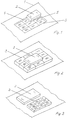
- FIG. 1 shows a switch arrangement on a center console 1 a four-door motor vehicle can be seen leading to the central Operation of electric windows is suitable, one Switching element 2 on a flat upper side of a switching field 3 is slidably arranged.
- the control panel 3 has nine adjacent switching sections on and is from aligned vertically to the flat top of the control panel 3 electrical contacts 4 limited.
- the switching element 2 is on its side surfaces provided with electrical contacts 5, the can be contacted with the electrical contacts 4.
- the Switching sections of the control panel 3 are not shown Provide locking elements with which the switching element 2 in Intervention can be brought.
- the respective electric windows individually or in Pre-selectable combination.
- the switching sections of the control panel 3 are corresponding the position of the respective window regulator in the motor vehicle Switching section I the front left window regulator, the Switching section III the right front window lifter, the Switching section VII the rear left window regulator and the Switching section IX assigned to the rear right window regulator.
- the switching section II are both front windows, the Switching section IV both left window regulator, the Switching section V all window regulators, the switching section VI both right window regulators and the switching section VII both assigned rear window regulator.
- the switching element 2 is designed as a double button can be switched between two polarity reversal positions Lowering assigned to the respective power window are.
- the switching element 2 is to each of the switching sections of the Panel 3 slidable and with the locking element of respective switching section can be brought into engagement in such a way that the electrical contacts 5 of the switching element 2 with the to respective switching section adjacent electrical contacts 4 of the control panel 3 are in contact.
- the switching element is located 2 in engagement with the switching section I, the electrical Contacts 5 of the switching element 2 with the electrical contacts 4, which adjoin the switching section I and assigned to it are in contact, causing the front left window regulator is selected.
- the switching element 2 is depressed on the corresponding side.
- the function assigned to the switching section V can also be preselected with one another in this way be that no contacting of the electrical contacts 4 and 5 with each other he follows.
- a switch arrangement can be seen from FIG. 2, the switching element 2 from the control panel 3 is surrounded, which has eight pressure switches, each one Window regulators or a combination of window regulators are assigned.
- the Switching element 2 is designed as a double button and projects upwards.
- the respective window regulator or the respective combination of window regulators is preselectable by pressing the corresponding pressure switch of the control panel 3 and can be raised by depressing the switching element 2 on the corresponding side or lowerable.
- the switching element 2 is arranged separately from the control panel 3, which has nine touch switches, each with a window regulator or a combination of window regulators assigned.
- the switching element 2 is a double touch switch educated.
- the respective window regulator or the respective combination of window regulators is preselectable by touching the corresponding touch switch of the control panel 3 and can be raised by touching the switching element 2 on the corresponding side or lowerable.
- the switch arrangements can be in the front area of the center console 1 between the driver and the front passenger or in the rear area of the center console 1 between be arranged on the rear seats for the passengers, the window regulators or the combinations of window regulators operated centrally by these people can be. With all versions, all or some switching sections can be arranged close to each other with a small distance.
Abstract
Description
Die Erfindung betrifft eine Schalteranordnung zum zentralen Bedienen einer Mehrzahl von Bauteilen oder Baugruppen eines Kraftfahrzeugs.The invention relates to a switch arrangement for the central Operating a plurality of components or assemblies one Motor vehicle.
Zum Bedienen von Bauteilen oder Baugruppen eines Kraftfahrzeugs werden im Allgemeinen Schalter eingesetzt, die sowohl im unmittelbaren Bereich der zu bedienenden Bauteile oder Baugruppen als auch in einer zentralen Position zum Bedienen der Bauteile oder Baugruppen angeordnet sind. Hierbei sind jeweils einem Schalter eine oder mehrere Bedienfunktionen eines bestimmten Bauteils oder einer bestimmten Baugruppe zugeordnet. Das heißt, daß zum Betätigen der Bauteile oder Baugruppen jeweils einzelne separate Schalter erforderlich sind, wobei die Schalter sequentiell bedient werden müssen. Bei räumlicher Nähe der Schalter zueinander kann eine parallele Bedienung mehrerer Bauteile oder Baugruppen nur auf komplizierte Weise erreicht werden, indem die Finger einer Hand einer Bedienperson auf mehrere Schalter ausgestreckt werden. Dies kann jedoch zu einer unzureichenden Betätigungskraft an den zur Betätigung beabsichtigten Schaltern bzw. zu einer unbeabsichtigten Betätigung von Schaltern oder einer bestimmten Bedienfunktion derselben führen, wodurch Fehlschaltungen verursacht werden können.For operating components or assemblies of a motor vehicle switches are generally used, both in immediate area of the components to be operated or Assemblies as well as in a central position for operation the components or assemblies are arranged. Here are one or more switch functions for each switch assigned to a specific component or a specific assembly. That means that to actuate the components or assemblies individual separate switches are required, the Switches must be operated sequentially. In close proximity the switch to each other can be operated in parallel Components or assemblies only achieved in a complicated way be put by the fingers of an operator's hand several switches can be extended. However, this can result in a insufficient actuation force on the actuators intended switches or unintended ones Actuation of switches or a certain operating function the same lead, causing incorrect switching can.
Es ist eine Aufgabe der Erfindung, eine Schalteranordnung zu schaffen, bei der mit einfachen Mitteln und geringem Fertigungsaufwand ein sicheres und zuverlässiges zentrales Bedienen einer oder mehrerer Bedienfunktionen von Bauteilen oder Baugruppen eines Kraftfahrzeugs einzeln, sequentiell oder parallel erreicht wird, wobei ein einfaches und schnelles Bedienen der Bauteile oder Baugruppen mit geringem Kraftaufwand ohne Auftreten von Fehlschaltungen möglich ist.It is an object of the invention to provide a switch assembly create, with simple means and little Manufacturing effort a safe and reliable central Operating one or more operating functions of components or assemblies of a motor vehicle individually, sequentially or is achieved in parallel, being a simple and quick Operating the components or assemblies with little effort is possible without faulty switching.
Erfindungsgemäß wird diese Aufgabe gelöst durch eine Schalteranordnung mit einem eine sichtbare Oberseite aufweisenden Schaltfeld mit einer Mehrzahl von aneinander angrenzenden Schaltabschnitten, welche mit elektrischen Kontakten versehen sind, und einem Schaltelement, welches längs der sichtbaren Oberseite zu jedem der Schaltabschnitte hin derart verschiebbar ist, daß diese durch Kontaktieren der elektrischen Kontakte schaltbar sind.According to the invention, this object is achieved by Switch arrangement with a visible top having switch panel with a plurality of one another adjacent switching sections, which with electrical Contacts are provided, and a switching element, which is longitudinal the visible top to each of the switching sections is so displaceable that this by contacting the electrical contacts are switchable.
Erfindungsgemäß wird diese Aufgabe weiterhin gelöst durch eine Schalteranordnung mit einem eine sichtbare Oberseite aufweisenden Schaltfeld mit einer Mehrzahl von aneinander angrenzenden Druck- oder Berührungsschaltern, und einem zwischen zwei Umpolstellungen schaltbaren Schaltelement, welches mit jedem der Druck- oder Berührungsschalter in elektrischen Kontakt bringbar ist.According to the invention, this object is further achieved by Switch arrangement with a visible top having switch panel with a plurality of one another adjacent pressure or touch switches, and one switching element switchable between two polarity reversal positions, which with each of the push or touch switches in electrical contact can be brought.
Eine derartige Schalteranordnung ermöglicht ein zentrales Bedienen einer Mehrzahl von Bauteilen oder Baugruppen, die jeweils einzeln oder in Kombination miteinander einem der Schaltabschnitte bzw. einem der Druck- oder Berührungsschalter zugeordnet werden können, wobei dem Schaltelement eine oder mehrere Bedienfunktionen der jeweiligen Bauteile oder Baugruppen zugeordnet werden können. Dabei können entweder die Bauteile oder Baugruppen mittels des jeweiligen Schaltabschnitts bzw. Druck- oder Berührungsschalters vorgewählt und die Bedienfunktion der jeweiligen Bauteile oder Baugruppen mittels des Schaltelements zugeschalten werden, oder die Bedienfunktion der jeweiligen Bauteile oder Baugruppen mittels des Schaltelements vorgewählt und die Bauteile oder Baugruppen mittels des jeweiligen Schaltabschnitts bzw. Druck- oder Berührungsschalters zugeschalten werden. Infolgedessen wird von dem Schaltelement und dem jeweiligen Schaltabschnitt bzw. Druck- oder Berührungsschalter ein elektrischer Kontakt ausgelöst, der bewirkt, daß die jeweilige Bedienfunktion der Bauteile oder Baugruppen des Kraftfahrzeugs ausgeführt wird.Such a switch arrangement enables a central one Operate a plurality of components or assemblies that individually or in combination with each other Switching sections or one of the pressure or touch switches can be assigned, the switching element one or several operating functions of the respective components or Assemblies can be assigned. Either the Components or assemblies using the respective Switching section or pressure or touch switch selected and the operating function of the respective components or Assemblies are switched on by means of the switching element, or the operating function of the respective components or assemblies selected by means of the switching element and the components or Assemblies by means of the respective switching section or pressure or Touch switch can be switched on. Consequently is from the switching element and the respective switching section or pressure or touch switch an electrical contact triggered, which causes the respective operating function of the Components or assemblies of the motor vehicle is executed.
Da die Schaltabschnitte bzw. die Druck- oder Berührungsschalter des Schaltfeldes aneinander angrenzen, wird nur ein geringer Einbauraum für die Schalteranordnung benötigt. Gleichzeitig ist eine kompakte Ausbildung des Schaltfeldes zusammen mit dem Schaltelement möglich.Because the switching sections or the pressure or touch switches of the panel adjoin each other, only a small one Installation space required for the switch arrangement. At the same time a compact design of the panel together with the Switching element possible.
Die erfindungsgemäße Schalteranordnung läßt nicht nur eine flexible Schaltung von Kombinationsmöglichkeiten für das Betätigen der Bauteile oder Baugruppen zu, sondern ermöglicht außerdem ein Erkennen der Lage der jeweiligen Bauteile oder Baugruppen aus der Lage des jeweils zugeordneten Schaltabschnitts bzw. Druck- oder Berührungsschalters innerhalb des Schaltfeldes, wodurch ein gute Übersichtlichkeit und ein schnelles Bedienen der Bauteile oder Baugruppen gewährleistet ist.The switch arrangement according to the invention does not leave only one flexible switching of possible combinations for the Activate the components or assemblies, but allows also recognizing the position of the respective components or Assemblies from the location of the assigned Switching section or pressure or touch switch within of the control panel, which ensures good clarity and a quick operation of the components or assemblies guaranteed is.
Die sichtbare Oberseite des Schaltfeldes kann in dem Kraftfahrzeug derart angeordnet sein, daß sie von einer Bedienperson deutlich erkennbar ist, wobei eine zusätzliche optische Kennzeichnung der Schaltabschnitte bzw. Druck- oder Berührungsschalter sowie des Schaltelements mit Hilfe von Beleuchtungsmitteln, die permanent oder nur während bestimmter Bedienvorgänge wirksam sind, zweckmäßig ist. Die Anordnung der Schaltabschnitte bzw. Druck- oder Berührungsschalter sowie des Schaltelements zueinander ermöglicht eine deutliche Fühlbarkeit durch die Bedienperson, so daß Fehlschaltungen vermieden werden und eine genaue Zuordnung des Schaltelements zu dem zu schaltenden Kontakt des jeweiligen Schaltabschnitts bzw. Druck-oder Berührungsschalters des Schaltfeldes erreicht wird.The visible top of the panel can be found in the Motor vehicle can be arranged so that it from a Operator is clearly recognizable, with an additional optical identification of the switching sections or pressure or Touch switch and the switching element with the help of Illuminants that are permanent or only during certain Operations are effective, is appropriate. The arrangement of the Switching sections or pressure or touch switches and the Switching element to each other enables a clear tactility by the operator, so that incorrect switching can be avoided and an exact assignment of the switching element to the switching contact of the respective switching section or pressure or Touch switch of the control panel is reached.
Im Falle des Schaltfeldes mit den Schaltabschnitten kann in vorteilhafter Weise die Oberseite des Schaltfeldes eben ausgebildet sein, und das Schaltelement eine ebene Unterseite aufweisen, welche auf der Oberseite des Schaltfeldes aufliegt. Dadurch ist es möglich, das Schaltelement ohne großen Kraftaufwand auf der ebenen Oberseite des Schaltfeldes entlang zu dem gewünschten Schaltabschnitt hin zu verschieben, wobei die Verschiebewege des Schaltelements aufgrund der platzsparenden Ausbildung des Schaltfeldes kurz sind. Die Verschiebung des Schaltelements zu den Schaltabschnitten des Schaltfeldes hin kann entlang vorbestimmter Linien oder in beliebiger Weise erfolgen. In the case of the control panel with the switching sections, in advantageously the top of the panel just be formed, and the switching element a flat bottom have, which rests on the top of the panel. This makes it possible to switch the switching element without large Apply force along the flat top of the panel to move to the desired switching section, whereby the displacement of the switching element due to the space-saving design of the control panel are short. The Shift of the switching element to the switching sections of the Switch panel can along predetermined lines or in done in any way.
Nach einer vorteilhaften Ausführungsform der Erfindung können die Schaltabschnitte durch Überbrücken ihrer elektrischen Kontakte mittels des Schaltelemente schaltbar sein. Hierbei kann das Überbrücken der elektrischen Kontakte mechanisch erfolgen, wobei das Schaltelement mit entsprechenden Mitteln versehen ist, die mit den elektrischen Kontakten der jeweiligen Schaltabschnitte des Schaltfeldes in Eingriff bringbar sind.According to an advantageous embodiment of the invention the switching sections by bridging their electrical Contacts can be switched by means of the switching elements. Here can bridge electrical contacts mechanically take place, the switching element with appropriate means is provided with the electrical contacts of the respective Switching sections of the control panel can be brought into engagement.
Nach einer weiteren vorteilhaften Ausführungsform der Erfindung kann das Schaltelement mit elektrischen Kontakten versehen sein, die zum Schalten der Schaltabschnitte mit deren elektrischen Kontakten kontaktierbar sind. Dabei gelangen die jeweiligen elektrischen Kontakte des Schaltelemente und des Schaltabschnitts in direkten Kontakt miteinander, um den entsprechenden Betätigungsvorgang an den Bauteilen und Baugruppen auszulösen. Hierbei ist es zweckmäßig, das Schaltelement mittels eines zusätzlichen Führungselements zu dem jeweiligen Schaltabschnitt hin zu führen, um anschließend den elektrischen Kontakt herstellen zu können.According to a further advantageous embodiment of the invention can provide the switching element with electrical contacts be used to switch the switching sections with their electrical contacts can be contacted. The respective electrical contacts of the switching elements and the Switching section in direct contact with each other to the corresponding actuation process on the components and Trigger assemblies. It is useful here Switching element by means of an additional guide element to lead the respective switching section to then to be able to make the electrical contact.
In vorteilhafter Weise können die Schaltabschnitte des Schaltfeldes mit Rastelementen zum Vorwählen der Bauteile oder Baugruppen versehen sein. Dies hat den Vorteil, daß das Schaltelement beim Verschieben zu dem jeweils gewünschten Schaltabschnitt des Schaltfeldes hin genau und zuverlässig in der Position des jeweiligen Schaltabschnitts einrasten und eine stabile fixierte Lage einnehmen kann. Dadurch ist eine bessere Bestimmung und Erkennung der Position des Schaltelemente auf dem Schaltfeld durch die Bedienperson möglich, wobei eine unbeabsichtigte Verschiebung des Schaltelemente durch Berührung desselben durch die Bedienperson besser vermieden wird.The switching sections of the Control panel with locking elements for preselecting the components or Assemblies are provided. This has the advantage that the Switching element when moving to the desired one Switching section of the switch panel accurate and reliable the position of the respective switching section and snap one can take a stable, fixed position. This is a better one Determination and detection of the position of the switching elements the control panel possible by the operator, one unintentional displacement of the switching elements by touch it is better avoided by the operator.
Im Falle des Schaltfeldes mit den Druck- oder Berührungsschaltern kann das Schaltelement in das Schaltfeld integriert angeordnet sein. Das hat den Vorteil, daß das Schaltelement zusammen mit den Druck- oder Berührungsschaltern ein kompakte Einheit bildet und sowohl das Schaltelement als auch die Druck- oder Berührungsschalter nur in einer einzigen Richtung zu betätigen sind. Der Einsatz von Berührungsschaltern ist dabei besonders vorteilhaft, da diese keine große Betätigungskraft erfordern. Die in das Schaltfeld integrierte Anordnung des Schaltelements gewährleistet eine einfache Bedienbarkeit und benötigt als kompakter Block einen geringen Einbauraum.In the case of the control panel with the pressure or Touch switches can switch the switching element in the panel be integrated. This has the advantage that the Switching element together with the pressure or touch switches forms a compact unit and both the switching element as also the pressure or touch switches only in one Direction. The use of touch switches is particularly advantageous since it is not a large one Require actuation force. The integrated in the panel Arrangement of the switching element ensures simple Usability and, as a compact block, requires little Installation space.
Nach einer bevorzugten Ausführungsform der Erfindung kann das Schaltelement von den Druck- oder Berührungsschaltern des Schaltfeldes umgeben sein und nach oben vorstehen. Dadurch liegt jeder Druck- oder Berührungsschalter in unmittelbarer Nähe zu dem Schaltelement, wodurch eine übersichtliche Bedienbarkeit von der Position des Schaltelements zu den jeweiligen Druck- oder Berührungsschaltern hin gewährleistet ist. Die nach oben vorstehende Anordnung des Schaltelements ermöglicht eine deutliche Erkennbarkeit desselben durch die Bedienperson und vermeidet ein unbeabsichtigtes Berühren von Druck- oder Berührungsschaltern des Schaltfeldes beim Betätigen des Schaltelements.According to a preferred embodiment of the invention, the Switching element from the pressure or touch switches of the Be surrounded and protrude upwards. Thereby every pressure or touch switch is in the immediate vicinity Proximity to the switching element, which makes a clear Usability from the position of the switching element to the respective pressure or touch switches guaranteed is. The above arrangement of the switching element enables the same to be clearly recognized by the Operator and prevents accidental touching of Pressure or touch switches of the control panel when actuated of the switching element.
Nach einer weiteren Ausführungsform der Erfindung kann das Schaltelement getrennt von dem Schaltfeld angeordnet sein. Das hat den Vorteil, daß eine gegenseitige Beeinflussung zwischen dem Schaltelement und dem Schaltfeld mit den Druck- oder Berührungsschaltern beim Betätigen derselben vermieden wird. Die Fläche des Schaltelements sowie der jeweiligen Druck- oder Berührungsschalter des Schaltfeldes kann dementsprechend großzügiger gestaltet werden, so daß Fehlbedienungen sowohl des Schaltelements als auch der Druck- oder Berührungsschalter vermieden werden.According to a further embodiment of the invention, the Switching element can be arranged separately from the control panel. The has the advantage that a mutual influence between the switching element and the control panel with the pressure or Touch switches when operating the same is avoided. The area of the switching element and the respective pressure or Touch switch of the control panel can accordingly be designed more generously so that incorrect operation of both the Switching element as well as the pressure or touch switch be avoided.
In vorteilhafter Weise können die Druck- oder Berührungsschalter des Schaltfeldes als Vorwahlelemente ausgebildet sein. Das hat den Vorteil, daß nach dem Vorwählen der jeweiligen Bauteile oder Baugruppen die Bedienfunktion derselben durch Schalten des Schaltelements zwischen den zwei Umpolstellungen verändert werden kann. Advantageously, the printing or Touch switch of the control panel as pre-selection elements be trained. This has the advantage that after preselection the operating function of the respective components or assemblies the same by switching the switching element between the two Reverse polarity can be changed.
Weiterhin ist es vorteilhaft, das Schaltelement als Doppeltaster oder Doppel-Berührungsschalter auszubilden. Dadurch können zwei unterschiedliche Bedienfunktionen, wie das Heben und Senken eines elektrischen Fensterhebers eines Kraftfahrzeugs, geschaltet werden. Hierbei ist kein Rückstellen des Schaltelements nach Beendigung des Betätigungsvorganges erforderlich, wie es beispielsweise bei einem Rastschalter der Fall ist, wodurch eine einfache Bedienbarkeit des Schaltelements gewährleistet ist.It is also advantageous to use the switching element as Train double switches or double touch switches. This allows two different operating functions, such as the Raising and lowering an electric window lifter Motor vehicle, are switched. There is no reset here of the switching element after completion of the actuation process required, as is the case, for example, with a latching switch Case is, which makes it easy to use Switching element is guaranteed.
Die Erfindung wird anhand von Ausführungsbeispielen näher
erläutert, die aus der Zeichnung ersichtlich sind. In der
Zeichnung zeigen:
Aus Fig. 1 ist eine Schalteranordnung an einer Mittelkonsole 1
eines viertürigen Kraftfahrzeugs ersichtlich, die zum zentralen
Bedienen von elektrischen Fensterhebern geeignet ist, wobei ein
Schaltelement 2 auf einer ebenen Oberseite eines Schaltfeldes 3
verschiebbar angeordnet ist. Das Schaltfeld 3 weist neun
aneinander angrenzende Schaltabschnitte auf und wird von
vertikal zur ebenen Oberseite des Schaltfeldes 3 ausgerichteten
elektrischen Kontakten 4 begrenzt. Das Schaltelement 2 ist an
seinen Seitenflächen mit elektrischen Kontakten 5 versehen, die
mit den elektrischen Kontakten 4 kontaktierbar sind. Die
Schaltabschnitte des Schaltfeldes 3 sind mit nicht gezeigten
Rastelementen versehen, mit denen das Schaltelement 2 in
Eingriff bringbar ist.1 shows a switch arrangement on a center console 1
a four-door motor vehicle can be seen leading to the central
Operation of electric windows is suitable, one
Mittels der Schaltabschnitte des Schaltfeldes 3 sind die
jeweiligen elektrischen Fensterheber einzeln oder in
Kombination miteinander vorwählbar. Hierbei sind entsprechend
der Lage der jeweiligen Fensterheber in dem Kraftfahrzeug dem
Schaltabschnitt I der vordere linke Fensterheber, dem
Schaltabschnitt III der vordere rechte Fensterheber, dem
Schaltabschnitt VII der hintere linke Fensterheber und dem
Schaltabschnitt IX der hintere rechte Fensterheber zugeordnet.
Dem Schaltabschnitt II sind beide vordere Fensterheber, dem
Schaltabschnitt IV beide linke Fensterheber, dem
Schaltabschnitt V alle Fensterheber, dem Schaltabschnitt VI
beide rechte Fensterheber und dem Schaltabschnitt VII beide
hintere Fensterheber zugeordnet.By means of the switching sections of the
Das Schaltelement 2 ist als Doppeltaster ausgebildet, der
zwischen zwei Umpolstellungen schaltbar ist, die dem Heben bzw.
Senken der jeweiligen elektrischen Fensterheber zugeordnet
sind. Das Schaltelement 2 ist zu jedem der Schaltabschnitte des
Schaltfeldes 3 hin verschiebbar und mit dem Rastelement des
jeweiligen Schaltabschnitts derart in Eingriff bringbar, daß
die elektrischen Kontakte 5 des Schaltelements 2 mit den an den
jeweiligen Schaltabschnitt angrenzenden elektrischen Kontakten
4 des Schaltfeldes 3 in Kontakt stehen.The
Wie aus Fig. 1 ersichtlich ist, befindet sich das Schaltelement
2 in Eingriff mit dem Schaltabschnitt I, wobei die elektrischen
Kontakte 5 des Schaltelements 2 mit den elektrischen Kontakten
4, die an den Schaltabschnitt I angrenzen und diesem zugeordnet
sind, in Kontakt stehen, wodurch der vordere linke Fensterheber
vorgewählt ist. Zum Heben bzw. Senken des Fensterhebers wird
das Schaltelement 2 an der entsprechenden Seite niedergedrückt.As can be seen from Fig. 1, the switching element is located
2 in engagement with the switching section I, the
Da der Schaltabschnitt V keine angrenzenden elektrischen
Kontakte 4 aufweist, wird ein elektrischer Kontakt mittels
nicht gezeigten separaten Kontaktelementen zwischen dem
Schaltelement 2 und dem Schaltabschnitt V des Schaltfeldes 3
hergestellt.Since the switching section V has no adjacent
Durch logische Verknüpfung der elektrischen Kontakte 4 und 5
miteinander kann die dem Schaltabschnitt V zugeordnete Funktion auch derart vorgewählt
werden, daß gar keine Kontaktierung der elektrischen Kontakte 4 und 5 miteinander
erfolgt.By logically linking
Aus Fig. 2 ist eine Schalteranordnung ersichtlich, wobei das Schaltelement 2 von
dem Schaltfeld 3 umgeben ist, welches acht Druckschalter aufweist, die jeweils einem
Fensterheber bzw. einer Kombination von Fensterhebern zugeordnet sind. Das
Schaltelement 2 ist als Doppeltaster ausgebildet und steht nach oben vor.A switch arrangement can be seen from FIG. 2, the
Der jeweilige Fensterheber bzw. die jeweilige Kombination von Fensterhebern ist
durch Drücken des entsprechenden Druckschalters des Schaltfeldes 3 vorwählbar
und durch Niederdrücken des Schaltelements 2 an der entsprechenden Seite anhebbar
bzw. absenkbar.The respective window regulator or the respective combination of window regulators is
preselectable by pressing the corresponding pressure switch of the
Fig. 3 zeigt eine weitere Ausführungsform der Erfindung, wobei das Schaltelement 2
getrennt von dem Schaltfeld 3 angeordnet ist, das neun Berührungsschalter aufweist,
die jeweils einem Fensterheber bzw. einer Kombination von Fensterhebern
zugeordnet sind. Hierbei ist das Schaltelement 2 als Doppel-Berührungsschalter
ausgebildet.3 shows a further embodiment of the invention, the switching
Der jeweilige Fensterheber bzw. die jeweilige Kombination von Fensterhebern ist
durch Berühren des entsprechenden Berührungsschalters des Schaltfeldes 3 vorwählbar
und durch Berühren des Schaltelements 2 an der entsprechenden Seite anhebbar
bzw. absenkbar.The respective window regulator or the respective combination of window regulators is
preselectable by touching the corresponding touch switch of the
Die Schalteranordnungen können im vorderen Bereich der Mittelkonsole 1 zwischen
dem Fahrer und dem Beifahrer oder im hinteren Bereich der Mittelkonsole 1 zwischen
den Fahrgästen auf dem Fondsitzen angeordnet sein, wobei die Fensterheber
bzw. die Kombinationen von Fensterhebern von diesen Personen zentral bedient
werden können. Bei allen Ausführungen können alle oder einige Schaltabschnitte
mit einem kleinen Abstand voneinander nah beieinander angeordnet sein.The switch arrangements can be in the front area of the
Claims (11)
Applications Claiming Priority (2)
| Application Number | Priority Date | Filing Date | Title |
|---|---|---|---|
| DE1997114955 DE19714955A1 (en) | 1997-04-10 | 1997-04-10 | Switch assembly for car central component actuation |
| DE19714955 | 1997-04-10 |
Publications (2)
| Publication Number | Publication Date |
|---|---|
| EP0891893A2 true EP0891893A2 (en) | 1999-01-20 |
| EP0891893A3 EP0891893A3 (en) | 2001-01-24 |
Family
ID=7826104
Family Applications (1)
| Application Number | Title | Priority Date | Filing Date |
|---|---|---|---|
| EP98106227A Withdrawn EP0891893A3 (en) | 1997-04-10 | 1998-04-06 | Switch assemly |
Country Status (2)
| Country | Link |
|---|---|
| EP (1) | EP0891893A3 (en) |
| DE (1) | DE19714955A1 (en) |
Cited By (2)
| Publication number | Priority date | Publication date | Assignee | Title |
|---|---|---|---|---|
| EP1431996A2 (en) * | 2002-12-20 | 2004-06-23 | Siemens Aktiengesellschaft | Input device for electric equipment |
| US8561008B2 (en) | 2005-03-10 | 2013-10-15 | Siemens Aktiengesellschaft | Presentation of hierarchical software structures |
Families Citing this family (1)
| Publication number | Priority date | Publication date | Assignee | Title |
|---|---|---|---|---|
| DE19910240A1 (en) * | 1999-03-08 | 2000-09-21 | Mannesmann Vdo Ag | Operating device |
Citations (4)
| Publication number | Priority date | Publication date | Assignee | Title |
|---|---|---|---|---|
| US4611102A (en) * | 1983-12-28 | 1986-09-09 | Takao Ooi Wa | Switch device for angularly adjusting outer rear mirrors of an automotive vehicle |
| US5012230A (en) * | 1987-04-07 | 1991-04-30 | Sony Corporation | Input device for digital processor based apparatus |
| US5111006A (en) * | 1989-05-16 | 1992-05-05 | Kabushiki Kaisha Toka-Rika-Denki-Seisakusho | Switch device for power driven seat |
| US5111011A (en) * | 1990-07-26 | 1992-05-05 | Indak Manufacturing Corp. | Mirror control slide switch for automotive vehicles |
Family Cites Families (2)
| Publication number | Priority date | Publication date | Assignee | Title |
|---|---|---|---|---|
| DE3703546A1 (en) * | 1987-02-06 | 1988-08-18 | Telefunken Electronic Gmbh | Switch having an enclosed switching mat |
| DE4338171C1 (en) * | 1993-11-09 | 1995-04-20 | Daimler Benz Ag | Keyboard and display system |
-
1997
- 1997-04-10 DE DE1997114955 patent/DE19714955A1/en not_active Withdrawn
-
1998
- 1998-04-06 EP EP98106227A patent/EP0891893A3/en not_active Withdrawn
Patent Citations (4)
| Publication number | Priority date | Publication date | Assignee | Title |
|---|---|---|---|---|
| US4611102A (en) * | 1983-12-28 | 1986-09-09 | Takao Ooi Wa | Switch device for angularly adjusting outer rear mirrors of an automotive vehicle |
| US5012230A (en) * | 1987-04-07 | 1991-04-30 | Sony Corporation | Input device for digital processor based apparatus |
| US5111006A (en) * | 1989-05-16 | 1992-05-05 | Kabushiki Kaisha Toka-Rika-Denki-Seisakusho | Switch device for power driven seat |
| US5111011A (en) * | 1990-07-26 | 1992-05-05 | Indak Manufacturing Corp. | Mirror control slide switch for automotive vehicles |
Cited By (3)
| Publication number | Priority date | Publication date | Assignee | Title |
|---|---|---|---|---|
| EP1431996A2 (en) * | 2002-12-20 | 2004-06-23 | Siemens Aktiengesellschaft | Input device for electric equipment |
| EP1431996A3 (en) * | 2002-12-20 | 2006-08-09 | Siemens Aktiengesellschaft | Input device for electric equipment |
| US8561008B2 (en) | 2005-03-10 | 2013-10-15 | Siemens Aktiengesellschaft | Presentation of hierarchical software structures |
Also Published As
| Publication number | Publication date |
|---|---|
| EP0891893A3 (en) | 2001-01-24 |
| DE19714955A1 (en) | 1998-10-15 |
Similar Documents
| Publication | Publication Date | Title |
|---|---|---|
| DE602004010753T2 (en) | Keyboard with retractable buttons and key of such a keyboard particularly suitable for the dashboard of a vehicle | |
| DE2922276A1 (en) | COUNTER | |
| EP0234193A2 (en) | Switch arrangement | |
| DE19916924A1 (en) | Motor vehicle with a selection device | |
| DE102007051466A1 (en) | switching device | |
| DE102017113661B4 (en) | Motor vehicle operating device | |
| DE60102119T2 (en) | Switch for motor vehicle seat | |
| DE4012399A1 (en) | SWITCH DEVICE | |
| DE4215097C2 (en) | Switch arrangement | |
| DE8119605U1 (en) | "Push button switch" | |
| DE4244583C1 (en) | Manually operated control switch | |
| EP0608771A1 (en) | Device and method to actuate built-in components in motor véhicles | |
| DE3249955C2 (en) | Electrical multi-position switch | |
| DE19752774C2 (en) | Switch combination for operating electrically powered windows in a vehicle | |
| DE2933093A1 (en) | ADJUSTABLE VEHICLE SEAT | |
| EP0891893A2 (en) | Switch assemly | |
| DE19757231B4 (en) | Multi-function switching device for motor vehicles | |
| EP0817226A2 (en) | Tumbler switch | |
| DE102006028462B4 (en) | Switch for adjusting a vehicle seat | |
| DE2620192B2 (en) | Switches, in particular travel direction switches for industrial trucks with electric drives | |
| DE3835073A1 (en) | Electrical switch for a motor vehicle window winding device | |
| DE3416602C2 (en) | Keyboard for operating an air conditioning system of a motor vehicle | |
| DE102007042129B4 (en) | Multiple operating element | |
| DE102008018383B3 (en) | Input device i.e. push button device, for use in e.g. instrument panel of motor vehicle, has contact arrangements connected with actuating element by spring, and switching illumination of predetermined keys | |
| DE102005032447B4 (en) | Electrical switching device |
Legal Events
| Date | Code | Title | Description |
|---|---|---|---|
| PUAI | Public reference made under article 153(3) epc to a published international application that has entered the european phase |
Free format text: ORIGINAL CODE: 0009012 |
|
| AK | Designated contracting states |
Kind code of ref document: A2 Designated state(s): AT BE CH DE DK ES FI FR GB GR IE IT LI LU MC NL PT SE |
|
| AX | Request for extension of the european patent |
Free format text: AL;LT;LV;MK;RO;SI |
|
| PUAL | Search report despatched |
Free format text: ORIGINAL CODE: 0009013 |
|
| AK | Designated contracting states |
Kind code of ref document: A3 Designated state(s): AT BE CH DE DK ES FI FR GB GR IE IT LI LU MC NL PT SE |
|
| AX | Request for extension of the european patent |
Free format text: AL;LT;LV;MK;RO;SI |
|
| RIC1 | Information provided on ipc code assigned before grant |
Free format text: 7B 60R 16/00 A, 7H 01H 13/70 B |
|
| STAA | Information on the status of an ep patent application or granted ep patent |
Free format text: STATUS: THE APPLICATION IS DEEMED TO BE WITHDRAWN |
|
| 18D | Application deemed to be withdrawn |
Effective date: 20001101 |