EP0892545A2 - Image processing apparatus, method and recording medium therefor - Google Patents
Image processing apparatus, method and recording medium therefor Download PDFInfo
- Publication number
- EP0892545A2 EP0892545A2 EP98305700A EP98305700A EP0892545A2 EP 0892545 A2 EP0892545 A2 EP 0892545A2 EP 98305700 A EP98305700 A EP 98305700A EP 98305700 A EP98305700 A EP 98305700A EP 0892545 A2 EP0892545 A2 EP 0892545A2
- Authority
- EP
- European Patent Office
- Prior art keywords
- image
- predetermined information
- image processing
- processing apparatus
- input image
- Prior art date
- Legal status (The legal status is an assumption and is not a legal conclusion. Google has not performed a legal analysis and makes no representation as to the accuracy of the status listed.)
- Granted
Links
Images


Classifications
-
- H—ELECTRICITY
- H04—ELECTRIC COMMUNICATION TECHNIQUE
- H04N—PICTORIAL COMMUNICATION, e.g. TELEVISION
- H04N1/00—Scanning, transmission or reproduction of documents or the like, e.g. facsimile transmission; Details thereof
- H04N1/00838—Preventing unauthorised reproduction
- H04N1/00856—Preventive measures
- H04N1/00864—Modifying the reproduction, e.g. outputting a modified copy of a scanned original
- H04N1/00867—Modifying the reproduction, e.g. outputting a modified copy of a scanned original with additional data, e.g. by adding a warning message
- H04N1/0087—Modifying the reproduction, e.g. outputting a modified copy of a scanned original with additional data, e.g. by adding a warning message with hidden additional data, e.g. data invisible to the human eye
-
- H—ELECTRICITY
- H04—ELECTRIC COMMUNICATION TECHNIQUE
- H04N—PICTORIAL COMMUNICATION, e.g. TELEVISION
- H04N2201/00—Indexing scheme relating to scanning, transmission or reproduction of documents or the like, and to details thereof
- H04N2201/32—Circuits or arrangements for control or supervision between transmitter and receiver or between image input and image output device, e.g. between a still-image camera and its memory or between a still-image camera and a printer device
- H04N2201/3201—Display, printing, storage or transmission of additional information, e.g. ID code, date and time or title
- H04N2201/3204—Display, printing, storage or transmission of additional information, e.g. ID code, date and time or title of data relating to a user, sender, addressee, machine or electronic recording medium
- H04N2201/3205—Display, printing, storage or transmission of additional information, e.g. ID code, date and time or title of data relating to a user, sender, addressee, machine or electronic recording medium of identification information, e.g. name or ID code
-
- H—ELECTRICITY
- H04—ELECTRIC COMMUNICATION TECHNIQUE
- H04N—PICTORIAL COMMUNICATION, e.g. TELEVISION
- H04N2201/00—Indexing scheme relating to scanning, transmission or reproduction of documents or the like, and to details thereof
- H04N2201/32—Circuits or arrangements for control or supervision between transmitter and receiver or between image input and image output device, e.g. between a still-image camera and its memory or between a still-image camera and a printer device
- H04N2201/3201—Display, printing, storage or transmission of additional information, e.g. ID code, date and time or title
- H04N2201/3269—Display, printing, storage or transmission of additional information, e.g. ID code, date and time or title of machine readable codes or marks, e.g. bar codes or glyphs
- H04N2201/327—Display, printing, storage or transmission of additional information, e.g. ID code, date and time or title of machine readable codes or marks, e.g. bar codes or glyphs which are undetectable to the naked eye, e.g. embedded codes
Definitions
- the present invention relates to an image processing apparatus for adding predetermined information to an input image, and a method and a storage medium therefor.
- An object of the present invention is to provide an image processing apparatus, a method and a storage medium therefor, capable of individually or entirely solving the drawbacks mentioned in the foregoing.
- Another object of the present invention is, under the above-mentioned object, to enable, in storing image information with a predetermined image storage format, the addition of predetermined information to the input image with a method suitable for such storage format.
- Still another object of the present invention is, under the above-mentioned object, to enable, in adding predetermined information to the input image, the storage of image taking such addition of information into consideration.
- an image processing apparatus comprising:
- Still another object of the present invention is to provide an image processing apparatus, a method and a storage medium therefor, having a novel function or a novel mode of adding information to the given image information.
- the storage format of the present embodiment is composed of objects of two types, namely a directory (shaded in Fig. 1) and a file (non-shaded).
- a directory 1 constitutes a root directory, constituting the highest hierarchy in the storage format.
- the directory 1 includes two directories (directories 2, 3) and a file (file 1).
- the directory 2 includes an empty directory 4, and the directory 3 includes two files (files 2, 3).
- the image information and the image attribute information are stored in a structure constituted by the above-mentioned two objects.
- each image file (20) contains following components:
- the above-mentioned source image object (24) and converted image object (25) include following components:
- the file may also be composed of the image data of maximum resolution and the header thereof.
- the headers 37, 40, 43 contain the length of header stream, width and height of the image, number of tiles to be explained later, width and height of tile, number of channels, offset of tile header table, length of tile header entry, tile header table (consisting of tile offset, tile size, compression type and compression sub title).
- the tile offset indicates the position of the tile, while the time size indicates the amount of data in the tile, the compression type indicates whether the tile data are non-compressed image data, a single color, JPEG compressed image data or lack effective image data, and the compression sub type indicates the color in case of single-color data, or the interleaving type, chroma sub sampling method, presence/absence of internal color conversion and presence/absence of change in the JPEG table in case of JPEG compression.
- Fig. 4 shows an example of the image file consisting of plural images of different resolution levels.
- an image 40 of the maximum resolution is composed of X0 columns and Y0 rows
- an image 41 of the second largest resolution is composed of X0/2 columns x Y0/2 rows.
- the numbers of columns and rows are both reduced to 1/2 in succession until those of columns and rows become respectively equal to or less than M and N, and the images are memorized down to an image 42 of the minimum resolution.
- the image of each resolution layer is divided into tiles each consisting of M ⁇ N pixels.
- a blank portion may be generated in a part of the tiles at the right-hand end and/or at the lower end (indicated by a hatched area).
- the tile of M ⁇ N pixels is completed by inserting the pixel at the right-hand end or at the lower end repeatedly.
- the image of each tile is memorized in a data format of JPEG compression, single color or non compression.
- the JPEG compression is an image compressing method of international standard defined by ISO/IEC JTC1/SC29.
- the single color is a data format, in case an entire tile is substantially composed of a single color, of representing the color of the tile by a single color instead of memorizing the individual pixel values. This data format is effective particularly for an image generated by computer graphics.
- the image data divided into the tile as explained in the foregoing are stored in the sub image data file, and the total number of tiles, the size of each tile, the data start position, the data format etc. are stored in the sub image header.
- Fig. 6 shows an example of the distribution of data formats of the tiles when the images 40, 41, 42 in Fig. 5 are divided into tile images 50, 51, 52.
- the attribute 1 indicates a non-compressed image
- the attribute 2 indicates a JPEG compressed image
- the attribute 3 indicates a single color.
- the attribute of each of the images of the resolution levels 1 to n can be easily determined according to a predetermined rule.
- the tile of the resolution level 1 can be defined to have the attribute 1.
- the tile of the resolution level 1 can be defined to have the attribute 3.
- the tile of the resolution level 1 can be defined to have the attribute 2
- the tile of the resolution level 1 can be defined to have the attribute 2
- the tile of the resolution level 1 can be defined to have the attribute 2
- FIG. 7 An example of the hardware configuration in the present embodiment is shown in Fig. 7.
- a CPU 70 for executing the process sequence to be explained later; a RAM 71 used for example as a work area for the CPU 70; a ROM 72 storing the programs to be executed by the CPU; an operation unit 73 including a display unit and used as a user interface; a hard disk 74 for storing data of the above-described data formats; a removable disk 75 such as a CD-R, a DVD-RAM or a floppy disk for storing data of the above-described data formats; an input interface 76 consisting of a bidirectional interface for entering image information and other information from an input device 77 such as an image scanner, a digital camera, a digital video camera or the like; and an output interface 78 consisting of a bidirectional interface for outputting information to an external device through communication means such as a network 79.
- Fig. 8 shows the basic procedure executed by the CPU shown in Fig. 7.
- a step S1 enters the image information from the input device 77 such as an image scanner, a digital camera or a digital video camera through the input interface 76.
- a step S2 enters information associated with the image information and constituting the basis of the first to tenth attribute information described above. The entry is executed manually through the input interface 76 or the operation unit 73.
- a step S3 formats the image information, entered in the step S1, into the image file format of the above-described structure.
- a step S4 formats the attribute information, entered in the step S2, into the image file format of the above-described structure.
- a step S5 stores the formatted image and attribute information in the hard disk 74 or the removable disk 75.
- a step S10 develops the entered image information into image data of respective pixels.
- the image data of respective pixels are prepared by an expansion process in case the image information is entered in a compressed format such as JPEG compression, or a development process in case of entry in the PDL codes. Also in case the size of the entered image information has to be changed, the size conversion is achieved by trimming or zooming. This step is skipped if these processes are unnecessary.
- a step S20 executes a color space conversion into any of predetermined color spaces such as RGB (additive primary colors) space and YCC (luminance and chromaticity) space.
- RGB additive primary colors
- YCC luminance and chromaticity
- a step S30 executes formatting for the image of maximum resolution, namely resolution level 0, as will be explained later in more details. The subsequent steps are not executed in case the image information is formatted only in the maximum resolution level.
- a step S40 reduces the resolution to a half.
- the method of reduction is formatted as the ninth attribute described above.
- a step S50 executes formatting for thus prepared image of the resolution level 1.
- a step S60 executes a reduction process similar to that in the step S40.
- step S70 terminates the process by executing the formatting for the image of the resolution level n.
- a step S110 discriminates whether the entered image information is non-compressed pixel data, and the sequence jumps to a step S170 if the entered image information is non-compressed pixel data and does not require the development process.
- a step S120 discriminates whether the entered image information is encoded data, and, if so, a step S140 executes decoding.
- a step S130 discriminates whether the entered image information is command data such as PDL, and, if so, a step S150 executes development of the command.
- step S160 executes such process.
- a step S170 adjust the number of bits per pixel and the image size.
- a step S210 presets a color space in manual manner through the operation unit 73.
- a step S220 discriminates whether the color space of the entered image information coincides with the color space set in the step S210, and, in case of no coincidence, a step S230 executes the conversion of the color space.
- a step S310 divides the image into tiles, each of M ⁇ N pixels.
- a step S320 detects the attribute of the image of each of the divided tiles.
- a tile containing a character or a fine line is defined as a character/fine line tile;
- a tile containing relatively important information such as a human face is defined as an important tile;
- a tile of which all pixels are of same data (or if only a very limited number of pixels is different in value) is defined as a single color tile; and any other tile is defined as a halftone tile.
- a step S330 determines the data format of the tile according to the detected attribute. For example, the character/fine line tile and the important tile mentioned above are determined as the non-compression of the attribute 1, the halftone tile is determined as the JPEG compression of the attribute 2, and the single color tile is determined as the single color of the attribute 3.
- a step S340 processes the image data of each tile so as to attain the determined data format.
- the foregoing procedure is basically applicable, in a similar manner, to the formatting of the images of the resolution level 1 to n.
- a step S410 presets the reduction method in manual manner through the operation unit 73.
- a step S420 executes reduction on the image data of the original resolution, by thus set reduction method.
- the watermark means information related to the image information of the above-described image file and so added to the image information as to be invisible or inconspicuous to the human eyes.
- the first to tenth attribute information mentioned in the foregoing may be inserted as the watermark mentioned above.
- Fig. 14 shows the procedure of a watermark inserting method 1, which inserts the watermark information into the object image in a real image space.
- a step S510 selectively reads the attribute information of the above-described file format,stored in the hard disk 74 or the removable disk 75 such as a CD-R, a DVD-RAM or a floppy disk and usable as the watermark information.
- a step S520 effects enciphering on the extracted watermark information, and such enciphering can be achieved in various methods, such as a known conversion utilizing a random number table. Also the present invention is not limited by the enciphering method.
- a step S530 converts the enciphered watermark information, together with the pixels, into pattern data.
- a step S540 utilizes the obtained image data of the watermark information for mutual calculation with the image data of the object image in the real image space, thereby embedding the watermark information in the object image.
- the mutual calculation can for example an addition or a multiplication.
- the amplitude (dynamic range) of the watermark information is made sufficiently smaller than that of the object image, whereby the watermark information is added in inconspicuous manner to the human eyes.
- the color component of the watermark information to be added is selected as the B component of the RGB (additive primary color) data or the chromaticity component of the YCC (luminance and chromaticity) data, so as that the deterioration in image quality is not easily recognized by the human eyes.
- Fig. 15 shows the procedure of a watermark inserting method II, which inserts the watermark information into the object image in the frequency space.
- a step S610 selectively reads the attribute information of the above-described file format, stored in the hard disk 74 or the removable disk 75 such as a CD-R, a DVD-RAM or a floppy disk.
- a step S620 effects enciphering on the extracted watermark information, and such enciphering can be achieved in various methods, such as a known conversion utilizing a random number table.
- a step S630 converts the enciphered watermark information, together with the pixels, into pattern data.
- a step S640 converts the obtained image data of the watermark information into frequency components for example by orthogonal transformation.
- a step S650 converts the image data of the object image into frequency components for example by orthogonal transformation.
- a step S660 synthesizes the image data of the object image and the enciphered watermark information in the real image space, thereby embedding the watermark information into the object image.
- a step S670 executes inverse conversion of the synthesized image into the real image data.
- the process for the image data of each tile, in the step S340 in Fig. 12, is conducted in the following manner.
- a step S1000 discriminates whether the data format is in the attribute 1, and if so, a step S1010 inserts the watermark in the above-described method I.
- a step S1020 discriminates whether the data format is in the attribute 2, and, if so, a step S1030 inserts the watermark in the above-described method II, and a step S1040 executes block encoding. If the block encoding is conducted by a method employing orthogonal transformation such as the JPEG encoding, the inverse conversion in the step S670 in Fig. 15 can be omitted and the frequency components can be directly subjected to quantization and Huffman encoding.
- the watermark inserting method is selected according to the memory format of the image data, whereby the watermark can be inserted in a manner appropriate for each format.
- step S1020 identifies that the data format is not in the attribute 2
- the tile is identified as in the attribute 3 and the representative value of the tile is extracted.
- the watermark is not inserted in the tile of this attribute.
- the watermark is inserted with the content and the method same as in the foregoing, also for the images of the resolution levels 2 to (n-1).
- the watermark is inserted in a procedure shown in Fig. 17.
- the watermark is inserted by the above-described method I.
- the watermark information is added in the present embodiment in the unit of a tile of M ⁇ N pixels, the watermark information is so selected that it is accommodated in a size of M ⁇ N pixels after enciphering and pattern development.
- Figs. 18 to 22 show examples of the content of the watermark information to be inserted and the arrangement thereof.
- Fig. 18 shows an example of the tile as in Fig. 6, wherein a indicates the information to be inserted as the watermark.
- the content of the information a can be any or all of the aforementioned first to tenth attribute information, for example the name of producer of the original image and the date of preparation thereof.
- the information a is commonly inserted in the tiles of all the hierarchic layers.
- the name of the producer of the original image and the preparation date thereof can be obtained from the image of any layer so that the information source of the image data can be securely identified.
- Fig. 19 shows an example of the watermark insertion as in Fig. 18.
- a and b respectively indicate information to be inserted as the watermark.
- the content of the information a can be any or all of the aforementioned first to tenth attribute information, preferably a part thereof, for example the name of producer of the original image and the date of preparation thereof, while the content of the information b can be any or all of the aforementioned first to tenth attribute information, for example the name of the final storing person and the date and time of final storage.
- the insertion of the information a or b is switched according to the hierarchic layer.
- Such arrangement allows to increase the kind and the amount of the information to be inserted, according to the increase in the number of hierarchic layers.
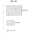
- Fig. 20 shows an example of the watermark insertion as in Fig. 18.
- a and b respectively indicate information to be inserted as the watermark.
- the content of the information a can be selected among the aforementioned first to tenth attribute information, for example the name of producer of the original image and the date of preparation thereof, while the content of the information b can be, among the aforementioned first to tenth attribute information, for example the name of the final storing person and the date and time of final storage.
- the information a and b are switched according to the tile position within the same hierarchic layer.
- the information a and b are alternately inserted in such a manner that same information is not present in mutually adjacent tiles.
- Such arrangement of switching the information a and b according to the tile position within the same hierarchic layer allows to increase the kind and the amount of the information to be inserted, for a same number of the hierarchic layers, and to obtain the information of plural kinds from the images of mutually adjacent plural tiles.
- Fig. 21 shows an example of the watermark insertion as in Fig. 18.
- a, b, c, d, e and f respectively indicate information to be inserted as the watermark.
- the content of the information a can be, among the aforementioned first to tenth attribute information, for example the name of producer of the original image and the date of preparation thereof; the content of the information b can be for example the name of the final storing person and the date and time of final storage, the content of the information c can be for example the name of the application used in the preparation; the content of the information d can be for example the keyword and the comments; the content of the information e can be for example the method of image information storage such as the compression parameters (in case of JPEG compression, quantization table data or Huffman table data such as SOI, DQT, DHT, EOI etc.); and the content of the information f can be for example the ID information of the device employed in the image input.
- the compression parameters in case of JPEG compression, quantization table data or Huffman table data such as SOI, DQT, DHT
- the information are switched according to the tile position with the same hierarchic layer, in such a manner that same information is not present in mutually adjacent tiles. Also the kind and amount of the inserted information are made larger for the higher resolution level and smaller for the lower resolution level.
- Such arrangement of switching the inserted information according to the tile position within the same hierarchic layer allows to increase the kind and the amount of the information to be inserted, for a same number of the hierarchic layers, and to obtain the information of plural kinds from the images of mutually adjacent plural tiles. Also the kind and the amount of the inserted information can be made larger for the higher resolution level.
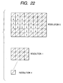
- Fig. 22 shows an example of the watermark insertion as in Fig. 18, wherein a indicates information to be inserted as the watermark.
- the content of the information a can be, among the aforementioned first to tenth attribute information, for example the name of producer of the original image and the date of preparation thereof.
- the information a is inserted into the tiles of a specified hierarchic layer.
- the foregoing embodiment employs plural watermark inserting methods, but there may be employed only one inserting method.
- all the watermarks may be inserted by the inserting method I or II.
- the use of a common watermark inserting method allows to simplify the software or the hardware for watermark insertion.
- the intensity of watermark insertion may be made different in different layers, even by employing a same inserting method.
- the watermark inserted in the image data of a high resolution level is so formed, in the mutual calculation with the image data of the object image, that the pattern data of the watermark information assume relatively small values in order to prevent the deterioration of the image quality
- the watermark inserted in the image data of a low resolution level is so formed, in the mutual calculation with the image data of the object image, that the pattern data of the watermark information assume relatively large values in order to prevent the deterioration of the watermark information.
- Such watermark inserting method selected according to the hierarchic level of the image data, allows to insert the intensity matching the resolution level of the image data.
- the watermark inserting method may be switched according to the resolution level.
- Such method allows to promptly insert the watermark with a relatively simple algorithm for the image of a high resolution level with a large data amount.
- the watermark is inserted in all the tiles according to the memory format of the image data, but it is also possible to insert the watermark in a part of the tiles of the object image, by periodically or randomly selecting the tiles in which the watermark is inserted.
- Such arrangement allows to suppress the deterioration of the image quality resulting from the watermark insertion.
- the embodiments of the present invention allow, in storing the image information with a predetermined image storage format, to add predetermined information to the input image with a method matching the storage format.
- Fig. 23 shows the procedure of the present embodiment on the image of the resolution level 0 in the step S20 shown in Fig. 9.
- a step S1310 inserts the watermark into the object image, in a method to be explained later.
- a step S1320 divides the image into tiles, each having a size of M ⁇ N pixels.
- a step S1330 detects the attribute of the image of the divided tile.
- a step S1340 determines the data format according to the detected attribute.
- a step S1350 processes the image data of each tile so as to assume the determined data format.
- the procedure described above can also be basically applied in a similar manner to the formatting of the images of the resolution levels 1 to no.
- Fig. 24 for explaining the detection of the attribute of the tile and the determination of the data format.
- a step S710 discriminates whether the watermark is inserted in the tile, and, if inserted, the data format is defined as the attribute 1 (step S720).
- a step S730 defines an important tile if the tile contains a character, a fine line or a relatively important information such as a human face, and the data format is defined as the non-compression attribute 1 (step S720).
- a step S740 defines a single color tile if all pixels of the tile are of same data (or if only a very limited number of pixels is different in value) and the data format is defined as the single color attribute 3 (step S760). Any other tile is defined as a halftone tile, with the JPEG compression attribute 2 (step 5750).
- the process on the image data of each tile in the step S340 in Fig. 23 is conducted in the following manner to the watermark insertion.
- a step S2000 discriminates whether the data format is in the attribute 1, and, if so, the process is skipped as the image data are not compressed.
- a step S2010 discriminates whether the data format is in the attribute 2, and, if so, a step S2020 executes block encoding. If the block encoding employs orthogonal transformation and quantization as in the JPEG encoding, the image is deteriorated by the non-reversible encoding.
- step S2020 identifies that the data format is not in the attribute 2
- the data format is identified as in the attribute 3 and the representative value of the tile is extracted (step S2030).
- the above-described method can also be applied to the images of the resolution levels 1 to n.
- the watermark information is added in the present embodiment in the unit of a tile of M ⁇ N pixels, the watermark information is so selected that it is accommodated in a size of M ⁇ N pixels after enciphering and pattern development.
- the encoding is not executed on the tile in which the watermark is inserted, but it is also possible to adopt encoding in so-called lossless encoding manner which does not result in the deterioration of the image quality.
- the control means for encoding is so designed as to select a predetermined encoding method in case predetermined information is added.
- control means for encoding may be so designed as to select a predetermined encoding parameter in case predetermined information is added.
- the present invention may be applied to a part of a system consisting of plural equipment (for example host computer, interface devices, reader, printer etc.) or a part of an apparatus consisting of a single equipment (such as a copying machine or a facsimile apparatus).
- plural equipment for example host computer, interface devices, reader, printer etc.
- an apparatus consisting of a single equipment (such as a copying machine or a facsimile apparatus).
- the present invention is not limited to the apparatus or the method for realizing the aforementioned embodiments but also includes a case where program codes of a software for realizing the aforementioned embodiments are supplied to a computer (CPU or MPU) in the above-mentioned system or apparatus and the functions of the aforementioned embodiments are realized by the computer of the above-mentioned system or apparatus, which causes various devices to function according to such program codes.
- a computer CPU or MPU
- program codes themselves of the software realize the functions of the aforementioned embodiments, and such program codes themselves and means for supplying the computer with such program codes, namely a storage medium storing the program codes are also included in the present invention.
- the storage medium storing such program codes can be, for example, a floppy disk, a hard disk, an optical disk, a magnetooptical disk, a CD-ROM, a magnetic tape, a non-volatile memory card or a ROM.
- the present invention also includes such program codes, not only in the case where the functions of the aforementioned embodiments are realized by the control of the above-mentioned computer on various devices according to the supplied program codes but also in a case where the program codes realize the aforementioned embodiments in cooperation with an operating system functioning on the computer or another application software.
- the present invention further includes a case wherein the supplied program codes are once stored in a function expansion board of the computer or a memory provided in a function expansion unit connected to the computer, and a CPU or the like provided in the function expansion board or the function expansion unit executes all the process or a part thereof according to the instructions of such program codes, thereby realizing the functions of the aforementioned embodiments.
- embodiments of the present invention can achieve, in adding predetermined information to the input image, image storage taking such addition of information into consideration.
Abstract
Description
Claims (46)
- An image processing apparatus comprising:division means for dividing an input image-into plural areas;control means for controlling the storage format of image data representing the input image in the unit of the divided area;conversion means for converting said image data into said storage format; andaddition means for adding predetermined information to said input image in the unit of said area.
- An image processing apparatus according to claim 1, wherein said addition means is adapted to add the predetermined information with a method variable according to the storage format of said image data.
- An image processing apparatus according to claim 1, wherein said addition means is adapted to add the predetermined information with an intensity variable according to the storage format of said image data.
- An image processing apparatus according to claim 1, wherein said addition means is adapted to add the predetermined information to the image data of a predetermined storage format within said image data.
- An image processing apparatus according to claim 1, wherein said addition means is adapted to add said predetermined information in a completed form within said area.
- An image processing apparatus according to claim 1, wherein said addition means is adapted to add the predetermined information to the image data of a predetermined color component within said image data.
- An image processing apparatus according to claim 1, wherein said addition means is adapted to add said predetermined information in a manner inconspicuous to the human eyes.
- An image processing apparatus comprising:division means for dividing an input image into plural areas;storage means for storing the input image in the unit of the divided area; andaddition means for adding predetermined information to said input image in the unit of said area.
- An image processing apparatus according to claim 8, wherein said addition means is adapted to add the predetermined information with a method variable according to the storage format of the input image by said storage means.
- An image processing apparatus according to claim 8, wherein said addition means is adapted to add the predetermined information with an intensity variable according to the storage format of the input image by said storage means.
- An image processing apparatus according to claim 8, wherein said addition means is adapted to add the predetermined information to the image data of a predetermined storage format within said input image.
- An image processing apparatus according to claim 8, wherein said addition means is adapted to add said predetermined information in a completed form within said area.
- An image processing apparatus according to claim 8, wherein said addition means is adapted to add the predetermined information to the image data of a predetermined color component within the image data representing said input image.
- An image processing apparatus according to claim 8, wherein said addition means is adapted to add said predetermined information in a manner inconspicuous to the human eyes.
- An image processing method comprising steps of:dividing an input image into plural areas;controlling the storage format of image data representing the input image in the unit of the divided area;converting said image data into said storage format; andadding predetermined information to said input image in the unit of said area.
- An image processing method comprising steps of:dividing an input image into plural areas;storing the input image in the unit of the divided area; andadding predetermined information to said input image in the unit of said area.
- A computer readable storage medium storing a program for executing an image processing method for adding predetermined information to an input image, the program comprising:a division step of dividing an input image into plural areas;a selection step of selecting the storage format of the image data representing the input image, in the unit of the divided area;a conversion step of converting said image data into said storage format; andan addition step of adding predetermined information to said input image in the unit of said area.
- A computer storage medium storing a program for executing an image processing method for adding predetermined information to an input image, the program comprising:a division step of dividing an input image into plural areas;a storage step of storing the input image in the unit of the divided area; andan addition step of adding predetermined information to said input image in the unit of said area.
- An image processing apparatus comprising:generation means for generating plural image data of mutually different resolution levels, representing a same input image; andhiding means for hiding predetermined information in each of the images of said plural resolution-levels in a manner inconspicuous to the human eyes.
- An image processing apparatus according to claim 19, wherein said hiding means is adapted to hide said predetermined information in an algorithm variable according to the resolution level of said image data.
- An image processing apparatus according to claim 19, wherein said hiding means is adapted to hide said predetermined information in an intensity variable according to the resolution level of said image data.
- An image processing apparatus according to claim 19, wherein said hiding means is adapted to select whether or not to hide said predetermined information according to the resolution level of said image data.
- An image processing apparatus according to claim 19, wherein said hiding means is adapted to select the content of said predetermined information according to the resolution level of said image data.
- An image processing apparatus according to claim 19, wherein said hiding means is adapted to control the amount of said predetermined information according to the resolution level of said image-data.
- An image processing apparatus according to claim 19, wherein said hiding means is adapted to add predetermined information to the image data of a predetermined color component among said image data.
- An image processing method comprising steps of:generating plural image data of mutually different resolution levels, representing a same input image; andhiding predetermined information in each of the images of said plural resolution levels in a manner inconspicuous to the human eyes.
- A computer readable storage medium storing a program for executing an image processing method for adding predetermined information to an input image, the program comprising:a generation step of generating plural image data of mutually different resolution levels, representing a same input image; anda hiding step of adding predetermined information in each of the images of said plural resolution levels in a manner inconspicuous to the human eyes.
- An image processing apparatus comprising:addition means for adding predetermined information to an input image;encoding means for encoding said input image; andcontrol means for controlling the encoding of said input image according to the addition state of said predetermined information.
- An image processing apparatus according to claim 28, wherein said addition means is adapted to add said predetermined information in the unit of a predetermined area.
- An image processing apparatus according to claim 28, wherein said addition means is adapted to add said predetermined information in a completed form within said area.
- An image processing apparatus according to claim 28, wherein said addition means is adapted to add the predetermined information to the image data of a predetermined color component within said image data.
- An image processing apparatus according to claim 28, wherein said addition means is adapted to add said predetermined information in a manner inconspicuous to the human eyes.
- An image processing apparatus according to claim 28, wherein said control means is adapted to select a predetermined encoding method by said encoding means in case said predetermined information is added by said addition means.
- An image processing apparatus according to claim 33, wherein said predetermined encoding method is a lossless encoding.
- An image processing apparatus according to claim 28, wherein said control means is adapted to select a predetermined encoding parameter by said encoding means in case said predetermined information is added by said addition means.
- An image processing apparatus according to claim 35, wherein said predetermined encoding parameter is an encoding parameter involving little deterioration in the image quality in the encoding.
- An image processing apparatus according to claim 28, wherein said control means is adapted not to execute the encoding by said encoding means in case said predetermined information is added by said addition means.
- An image processing apparatus according to claim 28, wherein said control means is adapted to control the encoding by said encoding means in the unit of a predetermined block.
- An image processing method comprising steps of:adding predetermined information to an input image;encoding said input image; andcontrolling the encoding of said input image according to the addition state of said predetermined information.
- An image processing apparatus comprising:division means for dividing an input image into plural areas;storage control means for storing the input image in the unit of the area divided by said division means; andaddition means for adding predetermined information to said input image in the unit of said area.
- An image processing apparatus according to claim 40, wherein said addition means is adapted to add said predetermined information in a completed form within said area.
- An image processing apparatus according to claim 40, wherein said addition means is adapted to add the predetermined information to the image data of a predetermined color component within said image data.
- An image processing apparatus according to claim 40, wherein said addition means is adapted to add said predetermined information in a manner inconspicuous to the human eyes.
- An image processing method comprising steps of:dividing an input image into plural areas;storing the input image in the unit of the divided area; andadding predetermined information to said input image in the unit of said area.
- A computer readable storage medium storing a program for executing an image processing method of adding predetermined information to an input image, the program comprising:an addition step of adding predetermined information to an input image;an encoding step of encoding said input image; anda control step of controlling the encoding of said input image according to the addition state of said predetermined information.
- A computer readable storage medium storing a program for executing an image processing method for adding predetermined information to an input image, the program comprising:a division step of dividing an input image into plural areas;a storage control step of storing the input image in the unit of the area divided by said division means; andan addition step of adding predetermined information to said input image in the unit of said area.
Applications Claiming Priority (9)
| Application Number | Priority Date | Filing Date | Title |
|---|---|---|---|
| JP192365/97 | 1997-07-17 | ||
| JP192364/97 | 1997-07-17 | ||
| JP19236597 | 1997-07-17 | ||
| JP19236497A JP3703258B2 (en) | 1997-07-17 | 1997-07-17 | Image processing apparatus and method, and storage medium |
| JP19236597A JP3728065B2 (en) | 1997-07-17 | 1997-07-17 | Image processing apparatus and method, and storage medium |
| JP19236497 | 1997-07-17 | ||
| JP25050497 | 1997-09-16 | ||
| JP25050497A JP3720546B2 (en) | 1997-09-16 | 1997-09-16 | Image processing apparatus and method, and storage medium |
| JP250504/97 | 1997-09-16 |
Publications (3)
| Publication Number | Publication Date |
|---|---|
| EP0892545A2 true EP0892545A2 (en) | 1999-01-20 |
| EP0892545A3 EP0892545A3 (en) | 2000-04-12 |
| EP0892545B1 EP0892545B1 (en) | 2006-07-12 |
Family
ID=27326599
Family Applications (1)
| Application Number | Title | Priority Date | Filing Date |
|---|---|---|---|
| EP98305700A Expired - Lifetime EP0892545B1 (en) | 1997-07-17 | 1998-07-16 | Image processing apparatus, method and recording medium therefor |
Country Status (4)
| Country | Link |
|---|---|
| US (1) | US6647125B2 (en) |
| EP (1) | EP0892545B1 (en) |
| AT (1) | ATE333189T1 (en) |
| DE (1) | DE69835188T2 (en) |
Cited By (3)
| Publication number | Priority date | Publication date | Assignee | Title |
|---|---|---|---|---|
| WO2002007000A2 (en) * | 2000-07-13 | 2002-01-24 | The Belo Company | System and method for associating historical information with sensory data and distribution thereof |
| CN114978898A (en) * | 2022-05-12 | 2022-08-30 | 泽景(西安)汽车电子有限责任公司 | Data transmission control method and device, head-up display and storage medium |
| CN114978898B (en) * | 2022-05-12 | 2024-04-12 | 泽景(西安)汽车电子有限责任公司 | Data transmission control method and device, head-up display and storage medium |
Families Citing this family (56)
| Publication number | Priority date | Publication date | Assignee | Title |
|---|---|---|---|---|
| US6272235B1 (en) * | 1997-03-03 | 2001-08-07 | Bacus Research Laboratories, Inc. | Method and apparatus for creating a virtual microscope slide |
| US6708309B1 (en) * | 1999-03-11 | 2004-03-16 | Roxio, Inc. | Method and system for viewing scalable documents |
| US7460157B2 (en) * | 2000-02-02 | 2008-12-02 | Fujifilm Corporation | Image storing-transferring method and apparatus, image processing method, image processing system, and image processor |
| US7136528B2 (en) * | 2000-02-11 | 2006-11-14 | Sony Corporation | System and method for editing digital images |
| US7262778B1 (en) | 2000-02-11 | 2007-08-28 | Sony Corporation | Automatic color adjustment of a template design |
| EP2040452A1 (en) * | 2000-03-29 | 2009-03-25 | Canon Kabushiki Kaisha | Printing apparatus connectable to a computer network and control method for image processing apparatus connectable to computer network |
| JP4124402B2 (en) * | 2000-03-31 | 2008-07-23 | 株式会社リコー | Image input device |
| US6804377B2 (en) * | 2000-04-19 | 2004-10-12 | Digimarc Corporation | Detecting information hidden out-of-phase in color channels |
| US6961441B1 (en) * | 2000-09-29 | 2005-11-01 | General Electric Company | Method and apparatus for steganographic embedding of meta-data |
| US6629104B1 (en) * | 2000-11-22 | 2003-09-30 | Eastman Kodak Company | Method for adding personalized metadata to a collection of digital images |
| US7315388B2 (en) * | 2001-01-24 | 2008-01-01 | Canon Kabushiki Kaisha | Image input/output control apparatus, image processing apparatus, image processing method, data communication apparatus, and data communication method |
| JP2003009102A (en) * | 2001-04-18 | 2003-01-10 | Victor Co Of Japan Ltd | Coding method of object data, transmitting method of object data, decoding method of object data, object data coding equipment, object data producing equipment, object data decoding equipment, program for coding object data, program for decoding object data and object data recording medium |
| US6947162B2 (en) * | 2001-08-30 | 2005-09-20 | Hewlett-Packard Development Company, L.P. | Systems and methods for converting the format of information |
| JP2003122466A (en) * | 2001-10-12 | 2003-04-25 | Fujitsu Ltd | List display data creation device and data creation program |
| US7130072B2 (en) * | 2002-02-08 | 2006-10-31 | Canon Kabushiki Kaisha | Multifunction system, image processing method, computer program and memory medium |
| US20030210803A1 (en) * | 2002-03-29 | 2003-11-13 | Canon Kabushiki Kaisha | Image processing apparatus and method |
| US7023475B2 (en) * | 2002-04-08 | 2006-04-04 | Hewlett-Packard Development Company, L.P. | System and method for identifying an object with captured images |
| US7343052B2 (en) * | 2002-04-09 | 2008-03-11 | Sonic Solutions | End-user-navigable set of zoomed-in images derived from a high-resolution master image |
| JP4344504B2 (en) * | 2002-04-17 | 2009-10-14 | 株式会社日立製作所 | Method for detecting digital watermark information |
| KR20040025368A (en) * | 2002-09-19 | 2004-03-24 | 삼성전자주식회사 | Method of advertisingprinting with advertisement and advertisement system using the same |
| US7646416B2 (en) * | 2002-09-20 | 2010-01-12 | Canon Kabushiki Kaisha | Image pickup apparatus with storage of original image, first reduced image, second reduced image and thumbnail data |
| US7120274B2 (en) * | 2002-12-31 | 2006-10-10 | Shutterfly, Inc. | Automated copyright detection in digital images |
| US8666108B2 (en) * | 2003-01-15 | 2014-03-04 | Alcatel Lucent | Watermarking scheme for digital video |
| US8699746B2 (en) * | 2003-01-15 | 2014-04-15 | Alcatel Lucent | Watermarking scheme for digital video |
| JP2004228811A (en) * | 2003-01-21 | 2004-08-12 | Ricoh Co Ltd | Image processor, image processing method and program for computer to perform execution |
| JP4369151B2 (en) * | 2003-03-31 | 2009-11-18 | セイコーエプソン株式会社 | Image processing apparatus, image processing method, and program used therefor |
| JP2004362091A (en) * | 2003-06-03 | 2004-12-24 | Toshiba Corp | Data converter, data conversion system, and data storage control program |
| US20050129385A1 (en) * | 2003-09-16 | 2005-06-16 | Jmz Llc | Intelligent portable memory device with display |
| JP3960961B2 (en) * | 2003-09-19 | 2007-08-15 | 富士通株式会社 | Apparatus and method for applying correction information to software |
| US7441182B2 (en) * | 2003-10-23 | 2008-10-21 | Microsoft Corporation | Digital negatives |
| TWI262702B (en) * | 2004-08-26 | 2006-09-21 | Ace Cad Entpr Co Ltd | External original handwriting aligning and inputting device of mobile phone and aligning method |
| US7545997B2 (en) * | 2004-09-10 | 2009-06-09 | Xerox Corporation | Simulated high resolution using binary sub-sampling |
| US20060072166A1 (en) * | 2004-09-24 | 2006-04-06 | Nikon Corporation | Image processing device, method and program |
| US20060072780A1 (en) * | 2004-09-30 | 2006-04-06 | Zarrabizadeh Mohammad H | Watermarking scheme for analog video |
| US7837618B2 (en) * | 2004-11-24 | 2010-11-23 | Olympus Corporation | Endoscope control system |
| WO2006095646A1 (en) * | 2005-03-08 | 2006-09-14 | Pioneer Corporation | Information recording device and method, computer program, and information recording medium |
| JP2006319949A (en) * | 2005-04-11 | 2006-11-24 | Toshiba Tec Corp | Electronic watermark generating apparatus, method, and program for generating electronic watermark for lossy compressed image |
| JP2007166594A (en) * | 2005-11-17 | 2007-06-28 | Fujifilm Corp | System, method, and program for album preparation |
| JP2007288582A (en) * | 2006-04-18 | 2007-11-01 | Canon Inc | Encryption device and method, as well as program and storage medium, image forming apparatus |
| JP4732250B2 (en) * | 2006-06-14 | 2011-07-27 | キヤノン株式会社 | Information processing apparatus, control method, and computer program |
| US7492922B2 (en) * | 2006-09-01 | 2009-02-17 | Shutterfly, Inc. | Automated verification of copyrighted digital images |
| US9697229B2 (en) * | 2008-04-11 | 2017-07-04 | Adobe Systems Incorporated | Methods and systems for creating and storing metadata |
| US7983512B2 (en) * | 2008-06-24 | 2011-07-19 | Microsoft Corporation | Embedding large images within one another |
| US7933473B2 (en) * | 2008-06-24 | 2011-04-26 | Microsoft Corporation | Multiple resolution image storage |
| US8064733B2 (en) * | 2008-06-24 | 2011-11-22 | Microsoft Corporation | Variable resolution images |
| US8385669B2 (en) * | 2009-03-04 | 2013-02-26 | Microsoft Corporation | Scalable mutable tiled multi-resolution texture atlases |
| WO2010151669A1 (en) * | 2009-06-25 | 2010-12-29 | Joseph Tholl Miller | System and method for sustainable printing |
| JP5629435B2 (en) | 2009-06-30 | 2014-11-19 | キヤノン株式会社 | Information processing apparatus, information processing method, and program |
| JP5576754B2 (en) | 2010-09-29 | 2014-08-20 | キヤノン株式会社 | Radiation imaging device |
| JP2013025650A (en) * | 2011-07-23 | 2013-02-04 | Canon Inc | Image processing apparatus, image processing method, and program |
| US10044938B2 (en) * | 2012-02-08 | 2018-08-07 | Abukai, Inc. | Method and apparatus for processing images of receipts |
| JP5819378B2 (en) * | 2013-09-30 | 2015-11-24 | シャープ株式会社 | Image determination apparatus, image processing system, program, and recording medium |
| US9886732B2 (en) * | 2015-10-09 | 2018-02-06 | AppNexus Inc. | Systems and methods for pixel-based watermarking |
| US9967465B2 (en) * | 2016-05-18 | 2018-05-08 | Realtek Singapore Pte Ltd | Image frame processing method |
| US10264302B2 (en) * | 2016-09-30 | 2019-04-16 | Ricoh Company, Ltd. | Communication management apparatus, method and computer-readable storage medium for generating image data identification information |
| US11157503B2 (en) * | 2017-11-15 | 2021-10-26 | Stochastic Processes, LLC | Systems and methods for using crowd sourcing to score online content as it relates to a belief state |
Citations (3)
| Publication number | Priority date | Publication date | Assignee | Title |
|---|---|---|---|---|
| EP0581317A2 (en) * | 1992-07-31 | 1994-02-02 | Corbis Corporation | Method and system for digital image signatures |
| EP0590884A2 (en) * | 1992-09-28 | 1994-04-06 | Canon Kabushiki Kaisha | Image forming method and apparatus |
| US5568550A (en) * | 1994-10-05 | 1996-10-22 | Shmuel Ur | Method and system for identifying documents generated by an unauthorized software copy |
Family Cites Families (16)
| Publication number | Priority date | Publication date | Assignee | Title |
|---|---|---|---|---|
| US5038298A (en) | 1986-03-14 | 1991-08-06 | Canon Kabushiki Kaisha | Image output apparatus connectable to mutually different external data processing apparatus |
| US5157773A (en) | 1986-03-14 | 1992-10-20 | Canon Kabushiki Kaisha | Image data output apparatus |
| US5278400A (en) * | 1991-08-19 | 1994-01-11 | Xerox Corp | Multiple threshold encoding of machine readable code |
| US5245165A (en) * | 1991-12-27 | 1993-09-14 | Xerox Corporation | Self-clocking glyph code for encoding dual bit digital values robustly |
| JP3193098B2 (en) | 1992-02-27 | 2001-07-30 | キヤノン株式会社 | Image processing apparatus and method |
| US5369261A (en) * | 1992-02-12 | 1994-11-29 | Shamir; Harry | Multi-color information encoding system |
| US5748763A (en) * | 1993-11-18 | 1998-05-05 | Digimarc Corporation | Image steganography system featuring perceptually adaptive and globally scalable signal embedding |
| US5710834A (en) * | 1995-05-08 | 1998-01-20 | Digimarc Corporation | Method and apparatus responsive to a code signal conveyed through a graphic image |
| US5646997A (en) * | 1994-12-14 | 1997-07-08 | Barton; James M. | Method and apparatus for embedding authentication information within digital data |
| JPH0981763A (en) * | 1995-07-07 | 1997-03-28 | Oki Data:Kk | Method and device for compressing character and image mixed data |
| US5905819A (en) * | 1996-02-05 | 1999-05-18 | Eastman Kodak Company | Method and apparatus for hiding one image or pattern within another |
| US5983176A (en) * | 1996-05-24 | 1999-11-09 | Magnifi, Inc. | Evaluation of media content in media files |
| JPH1051642A (en) * | 1996-07-31 | 1998-02-20 | Fuji Xerox Co Ltd | Image processor |
| US5915027A (en) * | 1996-11-05 | 1999-06-22 | Nec Research Institute | Digital watermarking |
| US6049627A (en) * | 1997-05-28 | 2000-04-11 | Thomason Information Services, Inc. | Covert digital identifying indicia for digital image |
| US6092732A (en) * | 1998-01-29 | 2000-07-25 | Xerox Corporation | Selectively accented serpentine halftone patterns for embedding human readable information in images |
-
1998
- 1998-07-16 US US09/116,497 patent/US6647125B2/en not_active Expired - Lifetime
- 1998-07-16 EP EP98305700A patent/EP0892545B1/en not_active Expired - Lifetime
- 1998-07-16 DE DE69835188T patent/DE69835188T2/en not_active Expired - Lifetime
- 1998-07-16 AT AT98305700T patent/ATE333189T1/en not_active IP Right Cessation
Patent Citations (3)
| Publication number | Priority date | Publication date | Assignee | Title |
|---|---|---|---|---|
| EP0581317A2 (en) * | 1992-07-31 | 1994-02-02 | Corbis Corporation | Method and system for digital image signatures |
| EP0590884A2 (en) * | 1992-09-28 | 1994-04-06 | Canon Kabushiki Kaisha | Image forming method and apparatus |
| US5568550A (en) * | 1994-10-05 | 1996-10-22 | Shmuel Ur | Method and system for identifying documents generated by an unauthorized software copy |
Cited By (5)
| Publication number | Priority date | Publication date | Assignee | Title |
|---|---|---|---|---|
| WO2002007000A2 (en) * | 2000-07-13 | 2002-01-24 | The Belo Company | System and method for associating historical information with sensory data and distribution thereof |
| WO2002007000A3 (en) * | 2000-07-13 | 2004-02-26 | Belo Company | System and method for associating historical information with sensory data and distribution thereof |
| US6862556B2 (en) | 2000-07-13 | 2005-03-01 | Belo Company | System and method for associating historical information with sensory data and distribution thereof |
| CN114978898A (en) * | 2022-05-12 | 2022-08-30 | 泽景(西安)汽车电子有限责任公司 | Data transmission control method and device, head-up display and storage medium |
| CN114978898B (en) * | 2022-05-12 | 2024-04-12 | 泽景(西安)汽车电子有限责任公司 | Data transmission control method and device, head-up display and storage medium |
Also Published As
| Publication number | Publication date |
|---|---|
| DE69835188T2 (en) | 2006-12-14 |
| EP0892545A3 (en) | 2000-04-12 |
| EP0892545B1 (en) | 2006-07-12 |
| DE69835188D1 (en) | 2006-08-24 |
| US6647125B2 (en) | 2003-11-11 |
| ATE333189T1 (en) | 2006-08-15 |
| US20030123696A1 (en) | 2003-07-03 |
Similar Documents
| Publication | Publication Date | Title |
|---|---|---|
| EP0892545B1 (en) | Image processing apparatus, method and recording medium therefor | |
| US6591009B1 (en) | Information embedding method, apparatus and recording medium | |
| US6285784B1 (en) | Method of applying manipulations to an extended color gamut digital image | |
| US6426771B1 (en) | Image processing apparatus and method and computer readable memory storing the method | |
| US7170552B2 (en) | Digital imaging system and file format for storage and selective transmission of processed and unprocessed image data | |
| US6282312B1 (en) | System using one or more residual image(s) to represent an extended color gamut digital image | |
| KR100819995B1 (en) | Image processing apparatus and control method thereof, and recording medium | |
| JP2003087563A (en) | Image processing device and its control method | |
| JP2002118767A (en) | Processing method for extended color gamut digital image using image information parameter | |
| EP1146727B1 (en) | Method for representing an extended color gamut digital image on a hard-copy output medium | |
| EP1148707B1 (en) | Method of processing and paying for an extended color gamut digital image | |
| EP1398950A2 (en) | Image forming method, image processing apparatus, and image recording apparatus for forming an optimum viewing image from a captured image | |
| US5844688A (en) | Image processing system for converting a color processing command into a control signal using an external controller | |
| EP0991019B1 (en) | Method of applying manipulations to a color digital image | |
| US7557951B2 (en) | Image processor and image printer | |
| JP3728065B2 (en) | Image processing apparatus and method, and storage medium | |
| US20050012963A1 (en) | Image processing apparatus, image processing method, and computer product | |
| JP3720546B2 (en) | Image processing apparatus and method, and storage medium | |
| JP2007194810A (en) | Image processing device | |
| JP3703258B2 (en) | Image processing apparatus and method, and storage medium | |
| US7986443B2 (en) | Image processing apparatus, image processing method and memory medium | |
| JP2001186356A (en) | Picture compression device, picture compresion method and computer readable storage medium | |
| JP2006041792A (en) | Image processing apparatus | |
| JP2009272772A (en) | Image processor, image forming apparatus, image processing method, and computer program | |
| JP2007096459A (en) | Image data generator and image data processor |
Legal Events
| Date | Code | Title | Description |
|---|---|---|---|
| PUAI | Public reference made under article 153(3) epc to a published international application that has entered the european phase |
Free format text: ORIGINAL CODE: 0009012 |
|
| AK | Designated contracting states |
Kind code of ref document: A2 Designated state(s): AT BE CH CY DE DK ES FI FR GB GR IE IT LI LU MC NL PT SE |
|
| AX | Request for extension of the european patent |
Free format text: AL;LT;LV;MK;RO;SI |
|
| RIC1 | Information provided on ipc code assigned before grant |
Free format text: 7H 04N 1/00 A, 7H 04N 1/32 B |
|
| PUAL | Search report despatched |
Free format text: ORIGINAL CODE: 0009013 |
|
| AK | Designated contracting states |
Kind code of ref document: A3 Designated state(s): AT BE CH CY DE DK ES FI FR GB GR IE IT LI LU MC NL PT SE |
|
| AX | Request for extension of the european patent |
Free format text: AL;LT;LV;MK;RO;SI |
|
| 17P | Request for examination filed |
Effective date: 20000824 |
|
| AKX | Designation fees paid |
Free format text: AT BE CH CY DE DK ES FI FR GB GR IE IT LI LU MC NL PT SE |
|
| 17Q | First examination report despatched |
Effective date: 20030221 |
|
| GRAP | Despatch of communication of intention to grant a patent |
Free format text: ORIGINAL CODE: EPIDOSNIGR1 |
|
| GRAS | Grant fee paid |
Free format text: ORIGINAL CODE: EPIDOSNIGR3 |
|
| GRAA | (expected) grant |
Free format text: ORIGINAL CODE: 0009210 |
|
| AK | Designated contracting states |
Kind code of ref document: B1 Designated state(s): AT BE CH CY DE DK ES FI FR GB GR IE IT LI LU MC NL PT SE |
|
| PG25 | Lapsed in a contracting state [announced via postgrant information from national office to epo] |
Ref country code: NL Free format text: LAPSE BECAUSE OF FAILURE TO SUBMIT A TRANSLATION OF THE DESCRIPTION OR TO PAY THE FEE WITHIN THE PRESCRIBED TIME-LIMIT Effective date: 20060712 Ref country code: LI Free format text: LAPSE BECAUSE OF FAILURE TO SUBMIT A TRANSLATION OF THE DESCRIPTION OR TO PAY THE FEE WITHIN THE PRESCRIBED TIME-LIMIT Effective date: 20060712 Ref country code: IT Free format text: LAPSE BECAUSE OF FAILURE TO SUBMIT A TRANSLATION OF THE DESCRIPTION OR TO PAY THE FEE WITHIN THE PRESCRIBED TIME-LIMIT;WARNING: LAPSES OF ITALIAN PATENTS WITH EFFECTIVE DATE BEFORE 2007 MAY HAVE OCCURRED AT ANY TIME BEFORE 2007. THE CORRECT EFFECTIVE DATE MAY BE DIFFERENT FROM THE ONE RECORDED. Effective date: 20060712 Ref country code: FI Free format text: LAPSE BECAUSE OF FAILURE TO SUBMIT A TRANSLATION OF THE DESCRIPTION OR TO PAY THE FEE WITHIN THE PRESCRIBED TIME-LIMIT Effective date: 20060712 Ref country code: CH Free format text: LAPSE BECAUSE OF FAILURE TO SUBMIT A TRANSLATION OF THE DESCRIPTION OR TO PAY THE FEE WITHIN THE PRESCRIBED TIME-LIMIT Effective date: 20060712 Ref country code: BE Free format text: LAPSE BECAUSE OF FAILURE TO SUBMIT A TRANSLATION OF THE DESCRIPTION OR TO PAY THE FEE WITHIN THE PRESCRIBED TIME-LIMIT Effective date: 20060712 Ref country code: AT Free format text: LAPSE BECAUSE OF FAILURE TO SUBMIT A TRANSLATION OF THE DESCRIPTION OR TO PAY THE FEE WITHIN THE PRESCRIBED TIME-LIMIT Effective date: 20060712 |
|
| REG | Reference to a national code |
Ref country code: GB Ref legal event code: FG4D |
|
| REG | Reference to a national code |
Ref country code: CH Ref legal event code: EP |
|
| PG25 | Lapsed in a contracting state [announced via postgrant information from national office to epo] |
Ref country code: IE Free format text: LAPSE BECAUSE OF NON-PAYMENT OF DUE FEES Effective date: 20060717 |
|
| PG25 | Lapsed in a contracting state [announced via postgrant information from national office to epo] |
Ref country code: MC Free format text: LAPSE BECAUSE OF NON-PAYMENT OF DUE FEES Effective date: 20060731 |
|
| REG | Reference to a national code |
Ref country code: IE Ref legal event code: FG4D |
|
| REF | Corresponds to: |
Ref document number: 69835188 Country of ref document: DE Date of ref document: 20060824 Kind code of ref document: P |
|
| PG25 | Lapsed in a contracting state [announced via postgrant information from national office to epo] |
Ref country code: SE Free format text: LAPSE BECAUSE OF FAILURE TO SUBMIT A TRANSLATION OF THE DESCRIPTION OR TO PAY THE FEE WITHIN THE PRESCRIBED TIME-LIMIT Effective date: 20061012 Ref country code: DK Free format text: LAPSE BECAUSE OF FAILURE TO SUBMIT A TRANSLATION OF THE DESCRIPTION OR TO PAY THE FEE WITHIN THE PRESCRIBED TIME-LIMIT Effective date: 20061012 |
|
| PG25 | Lapsed in a contracting state [announced via postgrant information from national office to epo] |
Ref country code: ES Free format text: LAPSE BECAUSE OF FAILURE TO SUBMIT A TRANSLATION OF THE DESCRIPTION OR TO PAY THE FEE WITHIN THE PRESCRIBED TIME-LIMIT Effective date: 20061023 |
|
| PG25 | Lapsed in a contracting state [announced via postgrant information from national office to epo] |
Ref country code: PT Free format text: LAPSE BECAUSE OF FAILURE TO SUBMIT A TRANSLATION OF THE DESCRIPTION OR TO PAY THE FEE WITHIN THE PRESCRIBED TIME-LIMIT Effective date: 20061212 |
|
| ET | Fr: translation filed | ||
| NLV1 | Nl: lapsed or annulled due to failure to fulfill the requirements of art. 29p and 29m of the patents act | ||
| PLBE | No opposition filed within time limit |
Free format text: ORIGINAL CODE: 0009261 |
|
| STAA | Information on the status of an ep patent application or granted ep patent |
Free format text: STATUS: NO OPPOSITION FILED WITHIN TIME LIMIT |
|
| 26N | No opposition filed |
Effective date: 20070413 |
|
| PG25 | Lapsed in a contracting state [announced via postgrant information from national office to epo] |
Ref country code: GR Free format text: LAPSE BECAUSE OF FAILURE TO SUBMIT A TRANSLATION OF THE DESCRIPTION OR TO PAY THE FEE WITHIN THE PRESCRIBED TIME-LIMIT Effective date: 20061013 |
|
| PG25 | Lapsed in a contracting state [announced via postgrant information from national office to epo] |
Ref country code: LU Free format text: LAPSE BECAUSE OF NON-PAYMENT OF DUE FEES Effective date: 20060716 |
|
| PG25 | Lapsed in a contracting state [announced via postgrant information from national office to epo] |
Ref country code: CY Free format text: LAPSE BECAUSE OF FAILURE TO SUBMIT A TRANSLATION OF THE DESCRIPTION OR TO PAY THE FEE WITHIN THE PRESCRIBED TIME-LIMIT Effective date: 20060712 |
|
| PGFP | Annual fee paid to national office [announced via postgrant information from national office to epo] |
Ref country code: DE Payment date: 20140731 Year of fee payment: 17 |
|
| PGFP | Annual fee paid to national office [announced via postgrant information from national office to epo] |
Ref country code: FR Payment date: 20140728 Year of fee payment: 17 Ref country code: GB Payment date: 20140724 Year of fee payment: 17 |
|
| REG | Reference to a national code |
Ref country code: DE Ref legal event code: R119 Ref document number: 69835188 Country of ref document: DE |
|
| GBPC | Gb: european patent ceased through non-payment of renewal fee |
Effective date: 20150716 |
|
| PG25 | Lapsed in a contracting state [announced via postgrant information from national office to epo] |
Ref country code: GB Free format text: LAPSE BECAUSE OF NON-PAYMENT OF DUE FEES Effective date: 20150716 Ref country code: DE Free format text: LAPSE BECAUSE OF NON-PAYMENT OF DUE FEES Effective date: 20160202 |
|
| REG | Reference to a national code |
Ref country code: FR Ref legal event code: ST Effective date: 20160331 |
|
| PG25 | Lapsed in a contracting state [announced via postgrant information from national office to epo] |
Ref country code: FR Free format text: LAPSE BECAUSE OF NON-PAYMENT OF DUE FEES Effective date: 20150731 |