EP0892555A2 - Adaptive video coding method - Google Patents
Adaptive video coding method Download PDFInfo
- Publication number
- EP0892555A2 EP0892555A2 EP98113216A EP98113216A EP0892555A2 EP 0892555 A2 EP0892555 A2 EP 0892555A2 EP 98113216 A EP98113216 A EP 98113216A EP 98113216 A EP98113216 A EP 98113216A EP 0892555 A2 EP0892555 A2 EP 0892555A2
- Authority
- EP
- European Patent Office
- Prior art keywords
- rate
- encoding
- frames
- buffer
- objects
- Prior art date
- Legal status (The legal status is an assumption and is not a legal conclusion. Google has not performed a legal analysis and makes no representation as to the accuracy of the status listed.)
- Withdrawn
Links
Images


Classifications
-
- H—ELECTRICITY
- H04—ELECTRIC COMMUNICATION TECHNIQUE
- H04N—PICTORIAL COMMUNICATION, e.g. TELEVISION
- H04N19/00—Methods or arrangements for coding, decoding, compressing or decompressing digital video signals
- H04N19/50—Methods or arrangements for coding, decoding, compressing or decompressing digital video signals using predictive coding
- H04N19/587—Methods or arrangements for coding, decoding, compressing or decompressing digital video signals using predictive coding involving temporal sub-sampling or interpolation, e.g. decimation or subsequent interpolation of pictures in a video sequence
-
- H—ELECTRICITY
- H04—ELECTRIC COMMUNICATION TECHNIQUE
- H04N—PICTORIAL COMMUNICATION, e.g. TELEVISION
- H04N19/00—Methods or arrangements for coding, decoding, compressing or decompressing digital video signals
- H04N19/10—Methods or arrangements for coding, decoding, compressing or decompressing digital video signals using adaptive coding
- H04N19/102—Methods or arrangements for coding, decoding, compressing or decompressing digital video signals using adaptive coding characterised by the element, parameter or selection affected or controlled by the adaptive coding
- H04N19/115—Selection of the code volume for a coding unit prior to coding
-
- H—ELECTRICITY
- H04—ELECTRIC COMMUNICATION TECHNIQUE
- H04N—PICTORIAL COMMUNICATION, e.g. TELEVISION
- H04N19/00—Methods or arrangements for coding, decoding, compressing or decompressing digital video signals
- H04N19/10—Methods or arrangements for coding, decoding, compressing or decompressing digital video signals using adaptive coding
- H04N19/102—Methods or arrangements for coding, decoding, compressing or decompressing digital video signals using adaptive coding characterised by the element, parameter or selection affected or controlled by the adaptive coding
- H04N19/124—Quantisation
-
- H—ELECTRICITY
- H04—ELECTRIC COMMUNICATION TECHNIQUE
- H04N—PICTORIAL COMMUNICATION, e.g. TELEVISION
- H04N19/00—Methods or arrangements for coding, decoding, compressing or decompressing digital video signals
- H04N19/10—Methods or arrangements for coding, decoding, compressing or decompressing digital video signals using adaptive coding
- H04N19/102—Methods or arrangements for coding, decoding, compressing or decompressing digital video signals using adaptive coding characterised by the element, parameter or selection affected or controlled by the adaptive coding
- H04N19/132—Sampling, masking or truncation of coding units, e.g. adaptive resampling, frame skipping, frame interpolation or high-frequency transform coefficient masking
-
- H—ELECTRICITY
- H04—ELECTRIC COMMUNICATION TECHNIQUE
- H04N—PICTORIAL COMMUNICATION, e.g. TELEVISION
- H04N19/00—Methods or arrangements for coding, decoding, compressing or decompressing digital video signals
- H04N19/10—Methods or arrangements for coding, decoding, compressing or decompressing digital video signals using adaptive coding
- H04N19/134—Methods or arrangements for coding, decoding, compressing or decompressing digital video signals using adaptive coding characterised by the element, parameter or criterion affecting or controlling the adaptive coding
- H04N19/136—Incoming video signal characteristics or properties
- H04N19/137—Motion inside a coding unit, e.g. average field, frame or block difference
-
- H—ELECTRICITY
- H04—ELECTRIC COMMUNICATION TECHNIQUE
- H04N—PICTORIAL COMMUNICATION, e.g. TELEVISION
- H04N19/00—Methods or arrangements for coding, decoding, compressing or decompressing digital video signals
- H04N19/10—Methods or arrangements for coding, decoding, compressing or decompressing digital video signals using adaptive coding
- H04N19/134—Methods or arrangements for coding, decoding, compressing or decompressing digital video signals using adaptive coding characterised by the element, parameter or criterion affecting or controlling the adaptive coding
- H04N19/136—Incoming video signal characteristics or properties
- H04N19/14—Coding unit complexity, e.g. amount of activity or edge presence estimation
-
- H—ELECTRICITY
- H04—ELECTRIC COMMUNICATION TECHNIQUE
- H04N—PICTORIAL COMMUNICATION, e.g. TELEVISION
- H04N19/00—Methods or arrangements for coding, decoding, compressing or decompressing digital video signals
- H04N19/10—Methods or arrangements for coding, decoding, compressing or decompressing digital video signals using adaptive coding
- H04N19/134—Methods or arrangements for coding, decoding, compressing or decompressing digital video signals using adaptive coding characterised by the element, parameter or criterion affecting or controlling the adaptive coding
- H04N19/146—Data rate or code amount at the encoder output
- H04N19/147—Data rate or code amount at the encoder output according to rate distortion criteria
-
- H—ELECTRICITY
- H04—ELECTRIC COMMUNICATION TECHNIQUE
- H04N—PICTORIAL COMMUNICATION, e.g. TELEVISION
- H04N19/00—Methods or arrangements for coding, decoding, compressing or decompressing digital video signals
- H04N19/10—Methods or arrangements for coding, decoding, compressing or decompressing digital video signals using adaptive coding
- H04N19/134—Methods or arrangements for coding, decoding, compressing or decompressing digital video signals using adaptive coding characterised by the element, parameter or criterion affecting or controlling the adaptive coding
- H04N19/146—Data rate or code amount at the encoder output
- H04N19/149—Data rate or code amount at the encoder output by estimating the code amount by means of a model, e.g. mathematical model or statistical model
-
- H—ELECTRICITY
- H04—ELECTRIC COMMUNICATION TECHNIQUE
- H04N—PICTORIAL COMMUNICATION, e.g. TELEVISION
- H04N19/00—Methods or arrangements for coding, decoding, compressing or decompressing digital video signals
- H04N19/10—Methods or arrangements for coding, decoding, compressing or decompressing digital video signals using adaptive coding
- H04N19/134—Methods or arrangements for coding, decoding, compressing or decompressing digital video signals using adaptive coding characterised by the element, parameter or criterion affecting or controlling the adaptive coding
- H04N19/154—Measured or subjectively estimated visual quality after decoding, e.g. measurement of distortion
-
- H—ELECTRICITY
- H04—ELECTRIC COMMUNICATION TECHNIQUE
- H04N—PICTORIAL COMMUNICATION, e.g. TELEVISION
- H04N19/00—Methods or arrangements for coding, decoding, compressing or decompressing digital video signals
- H04N19/10—Methods or arrangements for coding, decoding, compressing or decompressing digital video signals using adaptive coding
- H04N19/169—Methods or arrangements for coding, decoding, compressing or decompressing digital video signals using adaptive coding characterised by the coding unit, i.e. the structural portion or semantic portion of the video signal being the object or the subject of the adaptive coding
- H04N19/17—Methods or arrangements for coding, decoding, compressing or decompressing digital video signals using adaptive coding characterised by the coding unit, i.e. the structural portion or semantic portion of the video signal being the object or the subject of the adaptive coding the unit being an image region, e.g. an object
- H04N19/176—Methods or arrangements for coding, decoding, compressing or decompressing digital video signals using adaptive coding characterised by the coding unit, i.e. the structural portion or semantic portion of the video signal being the object or the subject of the adaptive coding the unit being an image region, e.g. an object the region being a block, e.g. a macroblock
-
- H—ELECTRICITY
- H04—ELECTRIC COMMUNICATION TECHNIQUE
- H04N—PICTORIAL COMMUNICATION, e.g. TELEVISION
- H04N19/00—Methods or arrangements for coding, decoding, compressing or decompressing digital video signals
- H04N19/20—Methods or arrangements for coding, decoding, compressing or decompressing digital video signals using video object coding
-
- H—ELECTRICITY
- H04—ELECTRIC COMMUNICATION TECHNIQUE
- H04N—PICTORIAL COMMUNICATION, e.g. TELEVISION
- H04N19/00—Methods or arrangements for coding, decoding, compressing or decompressing digital video signals
- H04N19/30—Methods or arrangements for coding, decoding, compressing or decompressing digital video signals using hierarchical techniques, e.g. scalability
- H04N19/37—Methods or arrangements for coding, decoding, compressing or decompressing digital video signals using hierarchical techniques, e.g. scalability with arrangements for assigning different transmission priorities to video input data or to video coded data
-
- H—ELECTRICITY
- H04—ELECTRIC COMMUNICATION TECHNIQUE
- H04N—PICTORIAL COMMUNICATION, e.g. TELEVISION
- H04N19/00—Methods or arrangements for coding, decoding, compressing or decompressing digital video signals
- H04N19/60—Methods or arrangements for coding, decoding, compressing or decompressing digital video signals using transform coding
- H04N19/61—Methods or arrangements for coding, decoding, compressing or decompressing digital video signals using transform coding in combination with predictive coding
-
- H—ELECTRICITY
- H04—ELECTRIC COMMUNICATION TECHNIQUE
- H04N—PICTORIAL COMMUNICATION, e.g. TELEVISION
- H04N19/00—Methods or arrangements for coding, decoding, compressing or decompressing digital video signals
- H04N19/10—Methods or arrangements for coding, decoding, compressing or decompressing digital video signals using adaptive coding
- H04N19/134—Methods or arrangements for coding, decoding, compressing or decompressing digital video signals using adaptive coding characterised by the element, parameter or criterion affecting or controlling the adaptive coding
- H04N19/146—Data rate or code amount at the encoder output
- H04N19/152—Data rate or code amount at the encoder output by measuring the fullness of the transmission buffer
-
- H—ELECTRICITY
- H04—ELECTRIC COMMUNICATION TECHNIQUE
- H04N—PICTORIAL COMMUNICATION, e.g. TELEVISION
- H04N19/00—Methods or arrangements for coding, decoding, compressing or decompressing digital video signals
- H04N19/30—Methods or arrangements for coding, decoding, compressing or decompressing digital video signals using hierarchical techniques, e.g. scalability
Definitions
- This invention relates to methods of coding video signals for digital storage and/or transmission of such signals using joint rate control for multiple video objects based on a quadratic rate-distortion model.
- this invention relates to a method of encoding video employing a joint rate control algorithm for multiple video object coding.
- the algorithm is based on the VM7 rate control scheme as described in the MPEG-4 Video Verification Model V7.0 ISO/ICC JTCI/SC29/WG11, Coding of Moving Picture and Associated Audio MPEG 97/N1642. April 1997, Bristol, U.K.
- the method follows a similar framework as that proposed previously by the current inventors in their parent application, with a change in the method of target distribution and introduction of a tool to take into account object shape in the rate control process. These modifications contribute to more homogeneous quality among video objects and better buffer regulation. As a whole, the method provides an effective means of coding multiple video objects so that the buffer is well-regulated and bits are appropriately distributed; yet it is flexible in deciding the necessary compromise between spatial and temporal quality.
- a basic method for compressing the bandwidth of digital color video signals which has been adopted by the Motion Picture Experts Group (MPEG) utilizes Discrete Cosine Transform (DCT) techniques.
- DCT Discrete Cosine Transform
- the MPEG approach employs motion compensation techniques.
- the MPEG standard achieves high data compression rates by developing information for a full frame of the image only every so often.
- the full image frames, or intra-coded pictures are called "I-frames", and contain the full frame information independent of any other frames. Between the I-frames, there are so-called B-frames and P-frames which store only image differences which occur relative to reference anchor frames.
- each frame of video sequence is partitioned into smaller blocks of pixel data and each block is subjected to the discrete cosine transformation function to convert the statistically dependent spatial domain picture elements (pixels) into independent frequency domain DCT coefficients.
- the blocks of data encoded according to intraframe coding (I-frames), consist of matrices of Discrete Cosine Coefficients.
- Respective 8 x 8 or 16 x 16 blocks of pixels are subjected to a Discrete Cosine Transform (DCT) to provide a coded signal.
- the coefficients are subjected to adaptive quantization, and then are run-length and variable-length encoded.
- respective blocks of transmitted data may include fewer than an 8 x 8 matrix of codewords.
- Macroblocks of intraframe encoded data will include, in addition to the DCT coefficients, information such as the level of quantization employed, a macroblock address or location indicator, and a macroblock type, the latter information being referred to as "header” or "overhead” information.
- Blocks of data encoded according to P or B interframe coding also consist of matrices of Discrete Cosine Coefficients. In this instance however, the coefficients represent residues or differences between a predicted 8 x 8 pixel matrix and the actual 8 x 8 pixel matrix. These coefficients are subjected to quantization and run- and variable-length coding.
- I and P frames are designated anchor frames. Each P frame is predicted from the lastmost occurring anchor frame.
- Each B frame is predicted from one or both of the anchor frames between which it is disposed.
- the predictive coding process involves generating displacement vectors which indicate which block of an anchor frame most closely matches the block of the predicted frame currently being coded.
- the pixel data of the matched block in the anchor frame is subtracted, on a pixel-by-pixel basis, from the block of the frame being encoded, to develop the residues.
- the transformed residues and the vectors comprise the coded data for the predictive frames.
- the macroblocks include quantization, address and type information.
- the results are usually energy concentrated so that a few of the coefficients in a block contain the main part of the picture information.
- the coefficients are quantized in a known manner to effectively limit the dynamic range of the coefficients and the results are then run-length and variable-length encoded for application to a transmission medium.
- VM coding verification model
- MPEG-4 Video Verification Model Version 5.0 distributed by Adhoc group on MPEG-4 video VM editing to its members under the designation ISO/IEC JTC1/SC29/WG11 MPEG 96/N1469, November 1996, the contents of which are incorporated herein by reference
- representatives of the David Sarnoff Research Center proposed "A New Rate Control Scheme Using Quadratic Rate Distortion Model”.
- the MPEG-4 video coding format will produce a variable bit rate stream at the encoder from frame to frame (as was the case with prior schemes). Since the variable bit rate stream is to be transmitted over a fixed rate channel, a channel buffer is employed to smooth out the bit stream. In order to prevent the buffer from overflowing or underflowing, rate control of the encoding process is required.
- a target bit rate for each frame is calculated to accommodate the fact the output bit rate from the output of the encoder is constrained to a fixed bit rate while the bit rate resulting from picture encoding can vary over a relatively wide range (if left uncorrected), depending on the content of the image frame.
- the distortion measure associated with each frame is assumed to be the average quantization scale of the frame and the rate distortion function is modeled as a second order function of the inverse of the distortion measure.
- the target bit rate of the image is estimated by the number of bits left for coding the group of images, as well as the number of frames still to be encoded. The authors mention implementing their scheme at the picture level and also note a possibility for extending their scheme to the macroblock level.
- a block contains an edge boundary of an object
- the energy in that block after transformation includes a relatively large DC coefficient (top left corner of matrix) and randomly distributed AC coefficients throughout the matrix.
- a non-edge block usually is characterized by a similar large DC coefficient (top left corner) and a few (e.g. two) adjacent AC coefficients which are substantially larger than other coefficients associated with that block.
- This information relates to image changes in the spatial domain and, when combined with image difference information obtained from comparing successive frames (i.e. temporal differences) factors are available for distinguishing one video object (VO) from another.
- one or more video objects may be contained in an image frame or plane (VOP) and, in each successive frame, the relative positioning of video objects may be expected to change, denoting motion. At the same time, this motion assists in defining the objects.
- VOP image frame or plane
- MPEG-4 VM Under the MPEG-4 VM, additional objectives of content-based manipulation and independent bit stream coding have been imposed to provide added functionality at the decoder end of the system.
- the MPEG-4 objective complicates and imposes additional processing requirements on the process of predicting target bit rates for each frame as a result of the added overhead information such as the coding of shape information within the MPEG-4 encoder.
- the foregoing characteristics of the MPEG-4 VM, as well as information regarding identification of individual VO's is explained in greater detail in the above-referenced manual.
- individual video objects VO's
- a method which achieves a constant bit rate output when coding multiple video objects.
- This implementation makes use of a quadratic rate-distortion model.
- Each object is described by its own set of parameters. With these parameters, an initial target bit estimate is made for each object after a first frame is encoded. Based on output buffer fullness, the total target is adjusted and then distributed proportional to a parameter set representative of the activity of the objects in the frame. Activity is determined by reference to weighted ratios derived from motion, size and variance parameters associated with each object. A shape rate control parameter is also invoked. Based on the new individual targets and second order model parameters, appropriate quantization parameters can be calculated for each video object. This method assures that the target bit rate is achieved for low latency video coding.
- control information may be applied jointly with respect to video objects (VO's), rather than entire frames.
- a method for performing joint bit rate control can be broken down into a pre-encoding stage and a post-encoding stage.
- a pre-encoding stage 20 comprises (i) target bit estimation 21, (ii) joint buffer control 22, (iii) a pre-frameskip control 24, and (iv) a quantization level calculation 25.
- the post-encoding stage 27 comprises (i) updating the rate-distortion model 28, and (ii) a post frameskip control 29.
- An important aspect of this scheme is that most blocks require previous operations to be complete for every video object (VO). For instance, inter-coding 31 of the next VO to be coded will not begin until all quantization levels for preceding VO's have been calculated. In this embodiment, all the VO's are coded at the same frame rate. However, many of the aspects of the current implementation anticipate a migration towards different frame rate for each VO. However, a more complex buffer control will be required.
- an adaptive video encoder ( Figure 4) is arranged to follow the method illustrated in Figure 2.
- a Digital Image Source 10 provides image information on a frame basis or on a Video Object (VO) basis to a video signal encoder 12 digitized form.
- the image is partitioned into spatially non-overlapping blocks of pixel data.
- the block size of 8 x 8 pixels or 16 x 16 pixels may be employed. Each partitioned block is then processed.
- a motion estimator 14 is used to estimate a motion vector for the input block with reference to a temporally close reference frame stored in a frame memory (previously) reconstructed VOP 16).
- the reference frame may be an original unprocessed frame or a previously coded frame.
- Bi-directional motion estimation such as that described in the MPEG standards can also be applied.
- a motion compensation block 11, a texture coding block 13, a shape coding block 15, a constant output bit rate buffer 17 and an MSDL multiplexer 19, all arranged as described in the MPEG-4 reference document, are provided.
- a rate control system 18 (as described in connection with Figure 2) is provided to perform added functions according to the invention of our parent application.
- the pre-encoding stage 20 further includes Initialization 26 (see Table I below).
- rate control variables e.g., first and second order complexities and MAD or Mean Absolute Difference information
- MAD Mean Absolute Difference information
- the encoder rate-distortion function is modeled as:
- the model parameters, X1 i and X2 i can be calculated separately for every VO.
- the target value, T_texture is decomposed into multiple T_texture i , which corresponds to the amount of bits used for coding the texture component only of the ith VO.
- the next step in the post encoding stage 27 is the post-frame skip control function 29.
- the buffer 17 has been updated. Overflow is prevented by checking the current buffer level against a skip margin, ⁇ . If the current buffer level is above the designated margin, frames are continually skipped, i.e., N_skip_post is incremented, until a specific criteria is met.
- this post-frame skip control is incremented until the criteria: Buff_level - N_skip_post ⁇ Buff_drain ⁇ (1- ⁇ ) ⁇ Buff_size is met.
- ⁇ is chosen to equal 0.2.
- the initial target bit rate is calculated based on the number of available bits for the segment and the number of bits used in the previous corresponding VO.
- a similar lower bound to the frame-based simulation is used so that minimum quality is guaranteed.
- the weighting ⁇ represents a contribution from the past frame and is set to 0.2 in that implementation.
- T_inc Buff_drain - T - Buff_level + ⁇ Buff_size if Buff_level - Buff_drain + T > ⁇ Buff_size
- T_dec Buff_level + T - (1- ⁇ ) ⁇ Buff_size if Buff_level + T > ( 1 - ⁇ ) ⁇ Buff_size .
- ⁇ is set to 0.1.
- the next step is to redistribute the bits so that consistent quality is maintained across different objects.
- the size of the object and the amount of activity which it is experiencing are obtained from the header information of the previously coded objects.
- a check is made to determine if the amount of bits used for the header of the previous frame exceed this bit count.
- N_skip_pre a non-zero value of N_skip_pre. This value is determined according to:
- the total target, T is distributed proportional to the header information of the previously coded frame as:
- the next task is to determine individual distortion measures which correspond to the desired rate. Treating the process separately for each VO and normalizing with respect to the MAD, leaves us to solve the classic quadratic:
- T_textured i is a result of subtracting the header bits from the total bits, it is possible to obtain small targets when performing low-bit-rate coding. To overcome this difficulty, we lower bound the target according to:
- the derived quantization parameter is lower bounded by LB_QUANT, otherwise the usual clipping between 1 and 31 is employed.
- the use of this parameter ensures that a relatively small amount of bits will go to coding the texture.
- the value of LB_QUANT should be chosen to be greater than 25.
- the fundamental approach set forth in our parent application, along with modifications regarding the target distribution 32, mode of operation 33, shape-related rate control 25' and post-frameskip 29' as shown in Figure 3 are employed.
- Two modes of operation are employed.
- the target distribution is based on the size, motion and variance (or MAD) of each object.
- the weights for each contribution depend on a mode of operation.
- a first mode is directed to low bit-rates (LowMode) and a second mode is directed to high bit-rates (HighMode).
- the new target distribution produces significant improvements in subjective quality. Modifications to the frameskip control prevent overflow of the register.
- the pre-encoding stage 20 comprises: (i) target bit estimation 21, (ii) joint buffer control 22, (iii) a pre-frameskip control 24, and (iv) a quantization level calculation 25'.
- the target bit estimation 21 is also associated with a modified target distribution function 32 as will be explained below.
- the quantization level calculation 25' is also associated with a shape rate-control function as will be explained.
- the post-encoding stage 27 comprises: (i) updating the rate-distortion model 28; (ii) a post-frameskip control 29' and a mode of operation function 33.
- Fig. 3 illustrates the present rate control process and includes additional features associated with the present invention which include the added target distribution 32, mode of operation 33, shape related rate control 25' and modified post-frameskip control 29'.
- a target was sought for every object in the scene and all video objects were coded at the same frame rate.
- the total bits for one frame were distributed proportional to the amount of header bits in the previous corresponding object.
- the bits are distributed proportional to a function which takes into account the relative motion, size and variance or "MAD" of each object.
- the MAD Mean Absolute Difference
- the MAD[i] factor is selected to be MAD 2 [i].
- the amount of bits for every VO can be expressed as: where MOT[i], SIZE[i] and MAD 2 [i] denote the relative ratios of the motion, size, and mean absolute difference parameters, respectively, and w m , w s and w v are weights which satisfy the equation:
- the post encoding function 27 includes mode of operation function 33. Specifically, two different modes of operation: one for encoding at low-bit rates and another for encoding at high bit-rates are provided.
- the availability of bits allows the process to be flexible in its target assignment to each VO. Under these circumstances, it is reasonable to impose homogeneous quality to each VO. Therefore, the inclusion of the MAD parameter is important to the target distribution and should carry the highest weighting.
- the availability of bits is limited, it is very difficult to achieve homogeneous quality among the various VO's.
- the skip threshold (SKIP_TH) was set to 2.
- the decision process to obtain a mode of operation can also be seen as a constraint on the temporal resolution. If the system is in LowMode, the encoder has skipped some specified number of frames. To obtain a reasonable compromise between the spatial and temporal quality, LowMode will impose a lower bound on the calculated quantization parameter. This lower bound, LB_QUANT, preferably is the same as that used in our previous application when the target from the joint buffer control was less than the amount of header bits used in the last frame.
- the modified function of the post-frameskip control 29' is to determine the current buffer 17 occupancy and ensure that encoding of future video objects will not cause the buffer 17 to overflow. In the previous implementation, this evaluation was based only on the current buffer 17 level. A positive value of N_skip_post was determined to satisfy the following condition: Buff_level - N_skip_post ⁇ Buff_drain ⁇ ( 1 - ⁇ ) ⁇ Buff_size In the current embodiment, information from the previous frame is utilized to obtain a better expectation of the amount of bits which may be required to be transmitted.
- B_last denotes the total number of bits spent encoding the previous frame or set of video objects.
- buffer 17 will readily accept the same amount of bits which were spent in the previous time coding instant. Any excess bits should be absorbed into the safety margin, subsequently preventing overflow from occurring.
- the gamma parameter, or skip margin is chosen to be 0.2.
- the binary shape information which defines a particular object is simply a mask which sets a pixel value up to "255" if it is part of the object or sets a pixel value to "0" if it is outside the object.
- rate control and rate reduction of the shape information can be achieved through size conversion of the alpha plane.
- the possible conversion ratios (CR) are 1, 1/2, or 1/4.
- a 16 x 16 macroblock (MB) may be down-converted to an 8 x 8 or a 4 x 4 block.
- Each macroblock containing relative shape information for the object can be down-converted for coding, then reconstructed at the original size.
- a conversion error is calculated for every 4 x 4 pixel block (PB).
- the conversion error is defined as the sum of absolute differences between the value of a pixel in the original PB and the reconstructed PB. If the conversion error is larger than sixteen times "Alpha Threshold" (i.e., 16 x AlphaTH), then this PB is referred to as an "Error PB". If there is one "Error PB" in a macroblock, then the conversion ratio (CR) for the macroblock is increased, with the maximum value being 1.
- AlphaTH initially is set to a value AlphaINI. During an I-frame and the first P-frame, this initial value will be used to code the shape for every object in those frames.
- the rate control algorithm will determine the mode of operation. If the mode of operation is determined to be LowMode, then the system will increment the current AlphaTH by AlphaINC. If the mode of operation is determined to be HighMode, then the system will decrement the current AlphaTH by AlphaDEC.
- the maximum and minimum values of AlphaTH are AlphaMAX and 0, respectively.
- This shape rate control algorithm is summarized in Fig. 4.
- the vertical axis indicates a corresponding AlphaTH at each coding instant.
- AlphaINC and AlphaDEC need not be constants, but rather functions of the current AlphaTH (e.g., larger steps when closer to zero and smaller steps when closer to AlphaMAX).
- Fig. 4 emphasizes the actions taken at each coding instant, where each coding instant is uniformly spaced.
- LowMode is only in operation after the total skipped frames in the previous post-encoding stage is greater than a selected value of a SKIP_TH, thereby making the time coding instants non-uniform.
- This adaptive selection of AlphaTH based on the mode of operation is quite effective in reducing the number of bits required for shape while maintaining sufficient quality at very low bit rates.
- the shape information can be coded using a low AlphaTH, resulting in very high quality object boundaries, as expected.
- This method provides additional functionality to the mode of operation and complements its efforts in regulating th temporal and spatial coding resolutions by freeing up additional texture bits and/or maintaining suitable buffer occupancy.
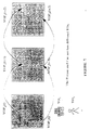
- Table 5 the average PSNR (peak signal to noise ratio) values for each VO are given under the low-bit rate conditions.
- the number of coded frames, the average quantization scale within each video object and the actual bit rate achieved are also provided.
- Table 6 The same information is provided in Table 6 for the high bit rate simulations.
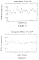
- plots of the buffer occupancy for each test sequence illustrate the exceptional control exhibited by the method under the low bit-rate and high bit-rate conditions.
- the modifications to the target distribution serve to better model the variance within an object. Since the variance has traditionally been used to indicate the amount of bits needed for coding, the distortion among objects will be more consistent.
- the adaptive selection of AlphaTH based on the mode of operation is quite effective in reducing the number: of bits for shape while maintaining sufficient quality at very low bit rates.
- the shape information can be coded using a low AlphaTH, resulting in very high quality object boundaries.
- This method provides additional functionality to the mode of operation and complements its efforts in regulating the temporal and spatial coding resolutions by freeing up additional texture bits and/or maintaining suitable buffer occupancy.
- the method is able to accommodate the functionality of the MPEG-4 standard in terms of coding multiple video objects for low-latency and low-bit-rate applications. It has also been shown to be scaleable to higher bit rate applications.
Abstract
Description
- Figure 1
- is a schematic pictorial representation of three successive image frames having two video objects (VO1 and VO2) and a background image, where each of the VO's moves from left to right in the scene over time;
- Figure 2
- is a block diagram illustrating steps in the method according to the invention of our parent application, along with the interrelationships among such steps;
- Figure 3
- is a block diagram illustrating steps in the method according to the present invention, along with the interrelationships among such steps;
- Figure 4
- is a block diagram of an MPEG-4 encoder which has been modified to implement the inventions of our parent application and/or the present invention;
- Figure 5
- is a diagram of the parameter "AlphaTH" as a function of time which illustrates a time sequence of shape rate control decisions based on mode of operation ("H" or "L") according to the present invention; and
- Figures 6
bis 16 - are a set of plots of buffer occupancy (bits) percentage versus frame for a series of video signal sequences representative of particular named images encoded with low and high bit rates in accordance with the present invention as identified in Table 2 and Table 4 below.


Buff_level - N_skip_post·Buff_drain < (1-γ)·Buff_size
is met.


Buff_level - N_skip_post·Buff_drain < (1-γ)·Buff_size
In the current embodiment, information from the previous frame is utilized to obtain a better expectation of the amount of bits which may be required to be transmitted. The new condition is as follows:
Buff_level + B_last - (N_skip_post+1)·Buff drain < (1-γ) · Buff_size,
where B_last denotes the total number of bits spent encoding the previous frame or set of video objects. In this way,


Claims (24)
- A method of adaptively encoding a sequence of frames of image information, wherein at least some of said frames contain a plurality of video objects, for providing a compressed video signal to a transmission channel by means of a buffer having a variable input bit rate and a substantially constant output bit rate comprising the steps of:encoding each of said video objects in each of a set of frames using coding means including a processor for performing discrete cosine transform to produce transform coefficients and a quantizer for quantizing the transform coefficients to generate image-representative code bits at a variable rate, said encoding step producing texture, motion and shape information for each said video object;storing said image representative code bits in said buffer;restricting the contents of said buffer with respect to a predetermined limit value by adjusting quantization parameters utilized by said quantizer with respect to a reference value according to a quadratic rate distortion model to increase or decrease the amount of code bits generated by said coding circuit for said video objects in successive ones of said frames;estimating a target number of bits for encoding each video object in each successive frame in a sequence occurring over a predetermined time interval following the first frame by distributing a target number of bits for all objects in each video object plane among said objects in accordance with a function of relative motion, size and variance parameters associated with corresponding objects in the corresponding object plane; andsetting said variable rate for encoding at one of at least a higher rate and a lower rate to avoid overflow of said buffer while preserving image quality.
- The method of claim 1 wherein said function further comprises a separate weighting factor for each of said motion, size and variance parameters.
- The method of claim 1 wherein said variance parameter is derived from calculation of a mean absolute difference value for each pixel of a video object in a given object plane as compared to the corresponding pixel in a preceding object plane.
- The method of claim 1 wherein said method further comprises the step of skipping the coding of a frame for a frame period whenever the difference between buffer bit capacity and current buffer level is less than a predetermined margin at the end of the encoding of all video objects in a frame.
- The method of claim 3 wherein said function of relative motion, size and variance parameters includes a variable proportional to the square of said mean absolute difference value.
- The method of claim 3 wherein said function is:where MOT[i], SIZE[i] and MAD[i] denote the relative ratios of motion, size and mean absolute difference parameters and Wm, Ws and Wv are weights which satisfy the expression


- The method of claim 6 wherein Wv is selected at a lower value and a higher value when said encoding rate is said lower rate and said higher rate, respectively.
- The method of claim 7 wherein said weights are selected asfor said lower encoding rate and
 for said higher encoding rate.
- The method of claim 7 wherein said weight Wv = 0 for said lower encoding rate and Wv is greater than Wm or Ws for said higher encoding rate.
- The method of claim 1 wherein said setting of said variable rate is determined by counting a number of consecutive skipped frames in a time interval immediately preceding said setting step.
- The method of claim 10 wherein said variable rate is set at said higher rate when said number of skipped frames is less than a predetermined number.
- The method of claim 11 wherein said predetermined number is two.
- The method of claim 4 wherein said variable rate is set at said higher rate when the number of said skipped frames is less than a predetermined number.
- A method of adaptively encoding a sequence of frames of image information, wherein at least some of said frames contain a plurality of video objects, for providing a compressed video signal to a transmission channel by means of a buffer having a variable input bit rate and a substantially constant output bit rate comprising the steps of:encoding each of said video objects in each of a set of frames using coding means including a processor for performing discrete cosine transform to produce transform coefficients and a quantizer for quantizing the transform coefficients to generate image-representative code bits at a variable rate, said encoding step producing texture, motion and shape information for each said video object;storing said image representative code bits in said buffer;restricting the contents of said buffer with respect to a predetermined limit value by adjusting quantization parameters utilized by said quantizer with respect to a reference value according to a quadratic rate distortion model to increase or decrease the amount of code bits generated by said coding circuit for said video objects in successive ones of said frames;estimating a target number of bits for encoding each video object in each successive frame in a sequence occurring over a predetermined time interval following the first frame by distributing a target number of bits for all objects in each video object plane among said objects in accordance with a function of relative motion, size and variance parameters associated with corresponding objects in the corresponding object plane; andcoding said shape information for each object according to a mask;size converting each macroblock of each said object for encoding according to a predetermined conversion ratio;reconstructing the original size of each said macroblock;determining a conversion error for each pixel block within said macro block;comparing said conversion errors to a predetermined threshold to identify error pixel blocks; andincreasing said conversion ratio and redetermining conversion errors and comparison thereof to said threshold until said threshold is not exceeded or until a maximum conversion ratio is reached.
- The method of claim 14 and further comprising:setting said variable rate for encoding at one of at least a higher rate and a lower rate to avoid overflow of said buffer while preserving image quality.
- The method of claim 15 wherein said setting of said variable rate is determined by counting a number of consecutive skipped frames in a time interval immediately preceding said setting step.
- The method of claim 16 wherein said function of relative motion, size and variance parameters includes a variable proportional to the square of said mean absolute difference value.
- The method of claim 17 wherein said function is:where MOT[i], SIZE[i] and MAD[i] denote the relative ratios of motion, size and mean absolute difference parameters and Wm, Ws and Wv are weights which satisfy the expression


- The method of claim 19 wherein Wv is selected at a lower value and a higher value when said encoding rate is said lower rate and said higher rate, respectively.
- A method of adaptively encoding a sequence of frames of image information, wherein at least some of said frames contain a plurality of video objects, for providing a compressed video signal to a transmission channel by means of a buffer having a variable input bit rate and a substantially constant output bit rate comprising the steps of:encoding each of said video objects in each of a set of frames using coding means including a processor for performing discrete cosine transform to produce transform coefficients and a quantizer for quantizing the transform coefficients to generate image-representative code bits at a variable rate, said encoding step producing texture, motion and shape information for each said video object;storing said image representative code bits in said buffer;restricting the contents of said buffer with respect to a predetermined limit value by adjusting quantization parameters utilized by said quantizer with respect to a reference value according to a quadratic rate distortion model to increase or decrease the amount of code bits generated by said coding circuit for said video objects in successive ones of said frames;setting said variable rate for encoding at one of at least a higher rate and a lower rate to avoid overflow of said buffer while preserving image quality;size converting said shape information for each macroblock of each said object according to a predetermined conversion ratio;determining a conversion error for each pixel block within each said macro block;comparing said conversion errors to a predetermined Alpha threshold to identify error pixel blocks;increasing said conversion ratio and redetermining conversion errors and comparison thereof to said Alpha threshold until said Alpha threshold is not exceeded or until a maximum conversion ratio is reached;skipping the coding of a frame for a frame period whenever the difference between buffer bit capacity and current buffer level is less than a predetermined margin at the end of the encoding of all video objects in a frame;said setting of said variable rate being determined by counting a number of consecutive skipped frames in a time interval immediately preceding said setting step, said variable rate being set at said higher rate when said number of skipped frames is less than a predetermined number and being set at said lower rate when said number of skipped frames is equal to or greater than said predetermined number;after encoding, determining whether said higher rate or said lower rate is operative; andincreasing said Alpha threshold if said lower rate is operative and decreasing said Alpha threshold if said higher rate is operative for a succeeding coding interval.
- The method of claim 20, wherein:said Alpha threshold is set initially at a value substantially midway between zero and a maximum value.
- The method of claim 20, wherein:said Alpha threshold is increased in value in increments of a first predetermined level and is decreased in value in decrements of a second predetermined level.
- The method of claim 21, wherein:said increment level is less than said decrement level.
- The method of claim 20 and further comprising:estimating a target number of bits for encoding each video object in each successive frame in a sequence occurring over a predetermined time interval following the first frame by distributing a target number of bits for all objects in each video object plane among said objects in accordance with a function of relative motion, size and variance parameters associated with corresponding objects in the corresponding object plane.
Applications Claiming Priority (2)
| Application Number | Priority Date | Filing Date | Title |
|---|---|---|---|
| US896867 | 1997-07-18 | ||
| US08/896,867 US5969764A (en) | 1997-02-14 | 1997-07-18 | Adaptive video coding method |
Publications (2)
| Publication Number | Publication Date |
|---|---|
| EP0892555A2 true EP0892555A2 (en) | 1999-01-20 |
| EP0892555A3 EP0892555A3 (en) | 2005-08-10 |
Family
ID=25406984
Family Applications (1)
| Application Number | Title | Priority Date | Filing Date |
|---|---|---|---|
| EP98113216A Withdrawn EP0892555A3 (en) | 1997-07-18 | 1998-07-15 | Adaptive video coding method |
Country Status (2)
| Country | Link |
|---|---|
| US (1) | US5969764A (en) |
| EP (1) | EP0892555A3 (en) |
Cited By (7)
| Publication number | Priority date | Publication date | Assignee | Title |
|---|---|---|---|---|
| GB2344954A (en) * | 1998-09-25 | 2000-06-21 | Nippon Telegraph & Telephone | Determining a target number of bits for each region within an image |
| WO2002096120A1 (en) * | 2001-05-25 | 2002-11-28 | Centre For Signal Processing, Nanyang Technological University | Bit rate control for video compression |
| AU768731B2 (en) * | 2000-12-14 | 2004-01-08 | Canon Kabushiki Kaisha | Matching a compressed image to available memory capacity |
| WO2006094035A1 (en) * | 2005-03-01 | 2006-09-08 | Qualcomm Incorporated | Content-adaptive background skipping for region-of-interest video coding |
| US7876821B2 (en) | 2002-09-05 | 2011-01-25 | Agency For Science, Technology And Research | Method and an apparatus for controlling the rate of a video sequence; a video encoding device |
| WO2018183902A1 (en) * | 2017-03-30 | 2018-10-04 | Qualcomm Incorporated | Zero block detection using adaptive rate model |
| US11541308B2 (en) * | 2007-12-05 | 2023-01-03 | Sony Interactive Entertainment LLC | Methods for compressing video for streaming video game content to remote clients |
Families Citing this family (94)
| Publication number | Priority date | Publication date | Assignee | Title |
|---|---|---|---|---|
| TW359919B (en) | 1996-07-17 | 1999-06-01 | Sony Corp | Image coding apparatus, image coding method, image decoding method, image decoding apparatus, image data transmitting method and recording medium |
| AU718453B2 (en) | 1996-07-17 | 2000-04-13 | Sony Corporation | Image coding and decoding using mapping coefficients corresponding to class information of pixel blocks |
| AU714554B2 (en) | 1996-07-17 | 2000-01-06 | Sony Corporation | Image coding and decoding using mapping coefficients corresponding to class information of pixel blocks |
| US6292591B1 (en) | 1996-07-17 | 2001-09-18 | Sony Coporation | Image coding and decoding using mapping coefficients corresponding to class information of pixel blocks |
| US6366614B1 (en) * | 1996-10-11 | 2002-04-02 | Qualcomm Inc. | Adaptive rate control for digital video compression |
| US6633609B1 (en) * | 1996-12-24 | 2003-10-14 | Intel Corporation | Method and apparatus for bit rate control in a digital video environment for arbitrary bandwidth |
| KR100256022B1 (en) * | 1997-10-14 | 2000-05-01 | 전주범 | Mode coding method for use in a binary shape encoding |
| WO1999021367A1 (en) * | 1997-10-20 | 1999-04-29 | Mitsubishi Denki Kabushiki Kaisha | Image encoder and image decoder |
| JP3915855B2 (en) | 1997-12-19 | 2007-05-16 | ソニー株式会社 | Image coding apparatus, image coding method, learning apparatus, and learning method |
| US6430317B1 (en) * | 1997-12-31 | 2002-08-06 | Sarnoff Corporation | Method and apparatus for estimating motion using block features obtained from an M-ary pyramid |
| US6724915B1 (en) * | 1998-03-13 | 2004-04-20 | Siemens Corporate Research, Inc. | Method for tracking a video object in a time-ordered sequence of image frames |
| US6434196B1 (en) * | 1998-04-03 | 2002-08-13 | Sarnoff Corporation | Method and apparatus for encoding video information |
| US8813137B2 (en) * | 1998-05-08 | 2014-08-19 | Qualcomm Incorporated | Apparatus and method for decoding digital image and audio signals |
| US6256423B1 (en) * | 1998-09-18 | 2001-07-03 | Sarnoff Corporation | Intra-frame quantizer selection for video compression |
| GB9822094D0 (en) * | 1998-10-09 | 1998-12-02 | Snell & Wilcox Ltd | Improvements in data compression |
| US6192080B1 (en) * | 1998-12-04 | 2001-02-20 | Mitsubishi Electric Research Laboratories, Inc. | Motion compensated digital video signal processing |
| JP3259702B2 (en) | 1998-12-24 | 2002-02-25 | 日本電気株式会社 | Moving picture variable bit rate coding apparatus and method |
| US8266657B2 (en) | 2001-03-15 | 2012-09-11 | Sling Media Inc. | Method for effectively implementing a multi-room television system |
| US6263503B1 (en) | 1999-05-26 | 2001-07-17 | Neal Margulis | Method for effectively implementing a wireless television system |
| US6792154B1 (en) | 1999-10-07 | 2004-09-14 | World Multicast.com, Inc | Video compression system and method using time |
| US7072398B2 (en) * | 2000-12-06 | 2006-07-04 | Kai-Kuang Ma | System and method for motion vector generation and analysis of digital video clips |
| US6985589B2 (en) * | 1999-12-02 | 2006-01-10 | Qualcomm Incorporated | Apparatus and method for encoding and storage of digital image and audio signals |
| JP3957937B2 (en) * | 1999-12-21 | 2007-08-15 | キヤノン株式会社 | Image processing apparatus and method, and storage medium |
| US6490320B1 (en) * | 2000-02-02 | 2002-12-03 | Mitsubishi Electric Research Laboratories Inc. | Adaptable bitstream video delivery system |
| US6650705B1 (en) | 2000-05-26 | 2003-11-18 | Mitsubishi Electric Research Laboratories Inc. | Method for encoding and transcoding multiple video objects with variable temporal resolution |
| US7260826B2 (en) * | 2000-05-31 | 2007-08-21 | Microsoft Corporation | Resource allocation in multi-stream IP network for optimized quality of service |
| JP2002064825A (en) * | 2000-08-23 | 2002-02-28 | Kddi Research & Development Laboratories Inc | Region dividing device of image |
| US7424058B1 (en) | 2000-09-28 | 2008-09-09 | Autodesk, Inc. | Variable bit-rate encoding |
| US7616690B2 (en) | 2000-10-31 | 2009-11-10 | Imec | Method and apparatus for adaptive encoding framed data sequences |
| JP4534106B2 (en) * | 2000-12-26 | 2010-09-01 | 日本電気株式会社 | Video encoding system and method |
| US7321624B1 (en) * | 2001-03-16 | 2008-01-22 | Objectvideo, Inc. | Bit-rate allocation system for object-based video encoding |
| US7209519B2 (en) | 2001-04-16 | 2007-04-24 | Mitsubishi Electric Research Laboratories, Inc. | Encoding a video with a variable frame-rate while minimizing total average distortion |
| US6671324B2 (en) * | 2001-04-16 | 2003-12-30 | Mitsubishi Electric Research Laboratories, Inc. | Estimating total average distortion in a video with variable frameskip |
| US7206453B2 (en) * | 2001-05-03 | 2007-04-17 | Microsoft Corporation | Dynamic filtering for lossy compression |
| KR100436765B1 (en) * | 2002-07-12 | 2004-06-23 | 삼성전자주식회사 | Apparatus and method for signal processing in a digital video system |
| KR100484148B1 (en) * | 2002-07-27 | 2005-04-18 | 삼성전자주식회사 | Advanced method for rate control and apparatus thereof |
| US7269136B2 (en) * | 2002-08-30 | 2007-09-11 | Sun Microsystems, Inc. | Methods and apparatus for avoidance of remote display packet buffer overflow |
| KR100540655B1 (en) * | 2003-01-23 | 2006-01-10 | 삼성전자주식회사 | Rate control method and apparatus in video coding |
| US7373004B2 (en) * | 2003-05-23 | 2008-05-13 | Silicon Integrated Systems Corp. | Apparatus for constant quality rate control in video compression and target bit allocator thereof |
| US7593580B2 (en) * | 2003-07-14 | 2009-09-22 | Texas Instruments Incorporated | Video encoding using parallel processors |
| US7738554B2 (en) | 2003-07-18 | 2010-06-15 | Microsoft Corporation | DC coefficient signaling at small quantization step sizes |
| US7580584B2 (en) | 2003-07-18 | 2009-08-25 | Microsoft Corporation | Adaptive multiple quantization |
| US10554985B2 (en) | 2003-07-18 | 2020-02-04 | Microsoft Technology Licensing, Llc | DC coefficient signaling at small quantization step sizes |
| US8218624B2 (en) | 2003-07-18 | 2012-07-10 | Microsoft Corporation | Fractional quantization step sizes for high bit rates |
| US7602851B2 (en) | 2003-07-18 | 2009-10-13 | Microsoft Corporation | Intelligent differential quantization of video coding |
| US7489726B2 (en) * | 2003-08-13 | 2009-02-10 | Mitsubishi Electric Research Laboratories, Inc. | Resource-constrained sampling of multiple compressed videos |
| US7324592B2 (en) * | 2003-08-13 | 2008-01-29 | Mitsubishi Electric Research Laboratories, Inc. | Resource-constrained encoding of multiple videos |
| KR100571824B1 (en) * | 2003-11-26 | 2006-04-17 | 삼성전자주식회사 | Method for encoding/decoding of embedding the ancillary data in MPEG-4 BSAC audio bitstream and apparatus using thereof |
| KR100556340B1 (en) * | 2004-01-13 | 2006-03-03 | (주)씨앤에스 테크놀로지 | Image Coding System |
| US7720145B2 (en) * | 2004-05-13 | 2010-05-18 | Ittiam Systems (P) Ltd. | Model based bit rate control for a macroblock encoder |
| US7801383B2 (en) | 2004-05-15 | 2010-09-21 | Microsoft Corporation | Embedded scalar quantizers with arbitrary dead-zone ratios |
| EP1769399B1 (en) | 2004-06-07 | 2020-03-18 | Sling Media L.L.C. | Personal media broadcasting system |
| US9998802B2 (en) * | 2004-06-07 | 2018-06-12 | Sling Media LLC | Systems and methods for creating variable length clips from a media stream |
| US7917932B2 (en) | 2005-06-07 | 2011-03-29 | Sling Media, Inc. | Personal video recorder functionality for placeshifting systems |
| US7769756B2 (en) | 2004-06-07 | 2010-08-03 | Sling Media, Inc. | Selection and presentation of context-relevant supplemental content and advertising |
| US7975062B2 (en) | 2004-06-07 | 2011-07-05 | Sling Media, Inc. | Capturing and sharing media content |
| US7669130B2 (en) * | 2005-04-15 | 2010-02-23 | Apple Inc. | Dynamic real-time playback |
| JP4040052B2 (en) * | 2005-05-24 | 2008-01-30 | 株式会社日立国際電気 | Image data compression device |
| US8422546B2 (en) | 2005-05-25 | 2013-04-16 | Microsoft Corporation | Adaptive video encoding using a perceptual model |
| US7961783B2 (en) * | 2005-07-07 | 2011-06-14 | Mediatek Incorporation | Methods and systems for rate control in video encoder |
| WO2007014216A2 (en) | 2005-07-22 | 2007-02-01 | Cernium Corporation | Directed attention digital video recordation |
| US8102878B2 (en) * | 2005-09-29 | 2012-01-24 | Qualcomm Incorporated | Video packet shaping for video telephony |
| US8842555B2 (en) * | 2005-10-21 | 2014-09-23 | Qualcomm Incorporated | Methods and systems for adaptive encoding of real-time information in packet-switched wireless communication systems |
| US8406309B2 (en) * | 2005-10-21 | 2013-03-26 | Qualcomm Incorporated | Video rate adaptation to reverse link conditions |
| US8548048B2 (en) * | 2005-10-27 | 2013-10-01 | Qualcomm Incorporated | Video source rate control for video telephony |
| US8514711B2 (en) * | 2005-10-21 | 2013-08-20 | Qualcomm Incorporated | Reverse link lower layer assisted video error control |
| US8605797B2 (en) * | 2006-02-15 | 2013-12-10 | Samsung Electronics Co., Ltd. | Method and system for partitioning and encoding of uncompressed video for transmission over wireless medium |
| US8059721B2 (en) | 2006-04-07 | 2011-11-15 | Microsoft Corporation | Estimating sample-domain distortion in the transform domain with rounding compensation |
| US7995649B2 (en) | 2006-04-07 | 2011-08-09 | Microsoft Corporation | Quantization adjustment based on texture level |
| US8503536B2 (en) | 2006-04-07 | 2013-08-06 | Microsoft Corporation | Quantization adjustments for DC shift artifacts |
| US8130828B2 (en) | 2006-04-07 | 2012-03-06 | Microsoft Corporation | Adjusting quantization to preserve non-zero AC coefficients |
| US7974340B2 (en) | 2006-04-07 | 2011-07-05 | Microsoft Corporation | Adaptive B-picture quantization control |
| US8711925B2 (en) | 2006-05-05 | 2014-04-29 | Microsoft Corporation | Flexible quantization |
| KR100790150B1 (en) * | 2006-07-28 | 2008-01-02 | 삼성전자주식회사 | Video encoder and method for encoding video data frame |
| KR101370478B1 (en) * | 2007-01-10 | 2014-03-06 | 퀄컴 인코포레이티드 | Content-and link-dependent coding adaptation for multimedia telephony |
| US8238424B2 (en) | 2007-02-09 | 2012-08-07 | Microsoft Corporation | Complexity-based adaptive preprocessing for multiple-pass video compression |
| US8498335B2 (en) | 2007-03-26 | 2013-07-30 | Microsoft Corporation | Adaptive deadzone size adjustment in quantization |
| US8243797B2 (en) | 2007-03-30 | 2012-08-14 | Microsoft Corporation | Regions of interest for quality adjustments |
| US8442337B2 (en) | 2007-04-18 | 2013-05-14 | Microsoft Corporation | Encoding adjustments for animation content |
| US8331438B2 (en) | 2007-06-05 | 2012-12-11 | Microsoft Corporation | Adaptive selection of picture-level quantization parameters for predicted video pictures |
| US8842739B2 (en) * | 2007-07-20 | 2014-09-23 | Samsung Electronics Co., Ltd. | Method and system for communication of uncompressed video information in wireless systems |
| US8243823B2 (en) | 2007-08-29 | 2012-08-14 | Samsung Electronics Co., Ltd. | Method and system for wireless communication of uncompressed video information |
| US8797850B2 (en) * | 2008-01-10 | 2014-08-05 | Qualcomm Incorporated | System and method to adapt to network congestion |
| US8750390B2 (en) * | 2008-01-10 | 2014-06-10 | Microsoft Corporation | Filtering and dithering as pre-processing before encoding |
| US8160132B2 (en) | 2008-02-15 | 2012-04-17 | Microsoft Corporation | Reducing key picture popping effects in video |
| US8189933B2 (en) | 2008-03-31 | 2012-05-29 | Microsoft Corporation | Classifying and controlling encoding quality for textured, dark smooth and smooth video content |
| US8897359B2 (en) | 2008-06-03 | 2014-11-25 | Microsoft Corporation | Adaptive quantization for enhancement layer video coding |
| US9571856B2 (en) | 2008-08-25 | 2017-02-14 | Microsoft Technology Licensing, Llc | Conversion operations in scalable video encoding and decoding |
| US9215467B2 (en) * | 2008-11-17 | 2015-12-15 | Checkvideo Llc | Analytics-modulated coding of surveillance video |
| US8179466B2 (en) * | 2009-03-11 | 2012-05-15 | Eastman Kodak Company | Capture of video with motion-speed determination and variable capture rate |
| US9369759B2 (en) * | 2009-04-15 | 2016-06-14 | Samsung Electronics Co., Ltd. | Method and system for progressive rate adaptation for uncompressed video communication in wireless systems |
| US8675726B2 (en) * | 2010-02-18 | 2014-03-18 | Blackberry Limited | Method and encoder for constrained soft-decision quantization in data compression |
| US9438652B2 (en) * | 2013-04-15 | 2016-09-06 | Opentv, Inc. | Tiered content streaming |
| CN109348226B (en) * | 2017-04-08 | 2022-11-11 | 腾讯科技(深圳)有限公司 | Picture file processing method and intelligent terminal |
Family Cites Families (9)
| Publication number | Priority date | Publication date | Assignee | Title |
|---|---|---|---|---|
| US5565921A (en) * | 1993-03-16 | 1996-10-15 | Olympus Optical Co., Ltd. | Motion-adaptive image signal processing system |
| KR100292138B1 (en) * | 1993-07-12 | 2002-06-20 | 이데이 노부유끼 | Transmitter and Receiver for Digital Video Signal |
| KR0139154B1 (en) * | 1994-07-08 | 1998-06-15 | 김광호 | Coding method in a neural network |
| US5552832A (en) * | 1994-10-26 | 1996-09-03 | Intel Corporation | Run-length encoding sequence for video signals |
| US5677969A (en) * | 1995-02-23 | 1997-10-14 | Motorola, Inc. | Method, rate controller, and system for preventing overflow and underflow of a decoder buffer in a video compression system |
| US5686963A (en) * | 1995-12-26 | 1997-11-11 | C-Cube Microsystems | Method for performing rate control in a video encoder which provides a bit budget for each frame while employing virtual buffers and virtual buffer verifiers |
| US5838830A (en) * | 1996-09-18 | 1998-11-17 | Sharp Laboratories Of America, Inc. | Vertex-based hierarchical shape representation and coding method and apparatus |
| US5883977A (en) * | 1996-12-30 | 1999-03-16 | Daewoo Electronics Co., Ltd. | Method and apparatus for encoding a video signal of a contour of an object |
| US5790196A (en) * | 1997-02-14 | 1998-08-04 | Mitsubishi Electric Information Technology Center America, Inc. | Adaptive video coding method |
-
1997
- 1997-07-18 US US08/896,867 patent/US5969764A/en not_active Expired - Fee Related
-
1998
- 1998-07-15 EP EP98113216A patent/EP0892555A3/en not_active Withdrawn
Non-Patent Citations (3)
| Title |
|---|
| "MPEG-4 VIDEO VERIFICATION MODEL VERSION 7.0" INTERNATIONAL ORGANIZATION FOR STANDARDIZATION, MPEG97N1642, April 1997 (1997-04), pages 1-271, XP000861690 * |
| TIHAO CHIANG ET AL: "A NEW RATE CONTROL SCHEME USING QUADRATIC RATE DISTORTION MODEL" IEEE TRANSACTIONS ON CIRCUITS AND SYSTEMS FOR VIDEO TECHNOLOGY, IEEE INC. NEW YORK, US, vol. 7, no. 1, February 1997 (1997-02), pages 246-250, XP000678897 ISSN: 1051-8215 * |
| VETRO A ET AL: "Joint rate control for coding multiple video objects" MULTIMEDIA SIGNAL PROCESSING, 1997., IEEE FIRST WORKSHOP ON PRINCETON, NJ, USA 23-25 JUNE 1997, NEW YORK, NY, USA,IEEE, US, 23 June 1997 (1997-06-23), pages 181-186, XP010233917 ISBN: 0-7803-3780-8 * |
Cited By (10)
| Publication number | Priority date | Publication date | Assignee | Title |
|---|---|---|---|---|
| GB2344954A (en) * | 1998-09-25 | 2000-06-21 | Nippon Telegraph & Telephone | Determining a target number of bits for each region within an image |
| GB2344954B (en) * | 1998-09-25 | 2003-04-09 | Nippon Telegraph & Telephone | Apparatus and method for encoding moving images and recording medium containing computer-readable encoding program |
| AU768731B2 (en) * | 2000-12-14 | 2004-01-08 | Canon Kabushiki Kaisha | Matching a compressed image to available memory capacity |
| WO2002096120A1 (en) * | 2001-05-25 | 2002-11-28 | Centre For Signal Processing, Nanyang Technological University | Bit rate control for video compression |
| US7876821B2 (en) | 2002-09-05 | 2011-01-25 | Agency For Science, Technology And Research | Method and an apparatus for controlling the rate of a video sequence; a video encoding device |
| WO2006094035A1 (en) * | 2005-03-01 | 2006-09-08 | Qualcomm Incorporated | Content-adaptive background skipping for region-of-interest video coding |
| US9667980B2 (en) | 2005-03-01 | 2017-05-30 | Qualcomm Incorporated | Content-adaptive background skipping for region-of-interest video coding |
| US11541308B2 (en) * | 2007-12-05 | 2023-01-03 | Sony Interactive Entertainment LLC | Methods for compressing video for streaming video game content to remote clients |
| WO2018183902A1 (en) * | 2017-03-30 | 2018-10-04 | Qualcomm Incorporated | Zero block detection using adaptive rate model |
| US10587880B2 (en) | 2017-03-30 | 2020-03-10 | Qualcomm Incorporated | Zero block detection using adaptive rate model |
Also Published As
| Publication number | Publication date |
|---|---|
| US5969764A (en) | 1999-10-19 |
| EP0892555A3 (en) | 2005-08-10 |
Similar Documents
| Publication | Publication Date | Title |
|---|---|---|
| US5969764A (en) | Adaptive video coding method | |
| US5790196A (en) | Adaptive video coding method | |
| US7023914B2 (en) | Video encoding apparatus and method | |
| US6463100B1 (en) | Adaptive quantization control method | |
| US6141380A (en) | Frame-level rate control for video compression | |
| US6823008B2 (en) | Video bitrate control method and device for digital video recording | |
| US5805222A (en) | Video coding apparatus | |
| JP2963416B2 (en) | Video encoding method and apparatus for controlling bit generation amount using quantization activity | |
| JP2002525989A (en) | Intra-frame quantizer selection for video compression | |
| US6879632B1 (en) | Apparatus for and method of variable bit rate video coding | |
| WO2002054772A2 (en) | Method of performing video encoding rate control using bit budget | |
| KR20080108538A (en) | Video coding | |
| JP2000350211A (en) | Method and device for encoding moving picture | |
| JP3508916B2 (en) | Moving image variable bit rate encoding method and apparatus | |
| JP4295828B2 (en) | Encoding with region information | |
| JP4179917B2 (en) | Video encoding apparatus and method | |
| JP2001028753A (en) | Dynamic image coder and its method | |
| JPH09294267A (en) | Image compression coder | |
| KR20070034869A (en) | Apparatus and method for controlling bit rate of video encoder | |
| JP3211778B2 (en) | Improved adaptive video coding method | |
| JP4193080B2 (en) | Encoding apparatus and method | |
| JP3200518B2 (en) | Image signal encoding device | |
| JP4035747B2 (en) | Encoding apparatus and encoding method | |
| Sun et al. | Scene adaptive parameters selection for MPEG syntax based HDTV coding | |
| JP3918208B2 (en) | Video data compression apparatus and method |
Legal Events
| Date | Code | Title | Description |
|---|---|---|---|
| PUAI | Public reference made under article 153(3) epc to a published international application that has entered the european phase |
Free format text: ORIGINAL CODE: 0009012 |
|
| AK | Designated contracting states |
Kind code of ref document: A2 Designated state(s): AT BE CH CY DE DK ES FI FR GB GR IE IT LI LU MC NL PT SE |
|
| AX | Request for extension of the european patent |
Free format text: AL;LT;LV;MK;RO;SI |
|
| PUAL | Search report despatched |
Free format text: ORIGINAL CODE: 0009013 |
|
| AK | Designated contracting states |
Kind code of ref document: A3 Designated state(s): AT BE CH CY DE DK ES FI FR GB GR IE IT LI LU MC NL PT SE |
|
| AX | Request for extension of the european patent |
Extension state: AL LT LV MK RO SI |
|
| 17P | Request for examination filed |
Effective date: 20050922 |
|
| AKX | Designation fees paid |
Designated state(s): DE FR GB |
|
| RAP1 | Party data changed (applicant data changed or rights of an application transferred) |
Owner name: MITSUBISHI DENKI KABUSHIKI KAISHA |
|
| RAP1 | Party data changed (applicant data changed or rights of an application transferred) |
Owner name: MITSUBISHI ELECTRIC RESEARCH LABORATORIES, INC. |
|
| 17Q | First examination report despatched |
Effective date: 20071012 |
|
| STAA | Information on the status of an ep patent application or granted ep patent |
Free format text: STATUS: THE APPLICATION IS DEEMED TO BE WITHDRAWN |
|
| 18D | Application deemed to be withdrawn |
Effective date: 20080223 |