EP0895081A2 - Paving material density indicator and method using capacitance - Google Patents
Paving material density indicator and method using capacitance Download PDFInfo
- Publication number
- EP0895081A2 EP0895081A2 EP98113897A EP98113897A EP0895081A2 EP 0895081 A2 EP0895081 A2 EP 0895081A2 EP 98113897 A EP98113897 A EP 98113897A EP 98113897 A EP98113897 A EP 98113897A EP 0895081 A2 EP0895081 A2 EP 0895081A2
- Authority
- EP
- European Patent Office
- Prior art keywords
- paving material
- sensor
- density
- shape
- controlled
- Prior art date
- Legal status (The legal status is an assumption and is not a legal conclusion. Google has not performed a legal analysis and makes no representation as to the accuracy of the status listed.)
- Withdrawn
Links
Images


Classifications
-
- G—PHYSICS
- G01—MEASURING; TESTING
- G01N—INVESTIGATING OR ANALYSING MATERIALS BY DETERMINING THEIR CHEMICAL OR PHYSICAL PROPERTIES
- G01N9/00—Investigating density or specific gravity of materials; Analysing materials by determining density or specific gravity
- G01N9/24—Investigating density or specific gravity of materials; Analysing materials by determining density or specific gravity by observing the transmission of wave or particle radiation through the material
-
- G—PHYSICS
- G01—MEASURING; TESTING
- G01N—INVESTIGATING OR ANALYSING MATERIALS BY DETERMINING THEIR CHEMICAL OR PHYSICAL PROPERTIES
- G01N33/00—Investigating or analysing materials by specific methods not covered by groups G01N1/00 - G01N31/00
- G01N33/42—Road-making materials
Definitions
- the present invention relates generally to paving equipment. More particularly, the present invention relates to a paving material density indicator and method for determining density of paving material by providing a sensor with a shape and size configured to have an electrical field with at least one of a controlled depth of penetration, controlled area, controlled shape, and controlled volume.
- paving material is usually laid at about 75% of acceptable compaction.
- the level of compaction is not readily apparent to the naked eye.
- measurement of dielectric properties of paving material is known to be very useful for determining material density, a key indicator of compaction level.
- Blackwell U.S. Patent No. 3,784,905.
- Blackwell's device measures dielectric properties of the asphalt which is representative of the change in density in the asphalt.
- the device to Blackwell has many disadvantages. For example, in order to obtain a reading, the Blackwell device must be moved at extremely slow speeds across the material being tested and, accordingly, requires an extended time period to provide a determination.
- the Blackwell device due to its excessive weight, also requires a large sled frame (contact area) to be dragged across the pavement surface.
- Another disadvantage is limited adjustability of the depth of measurement of the device caused by the given set of electrodes only being able to vary the depth of measurement by changing the height of the electrodes.
- a nuclear source is used to determine density of pavement material.
- This device has a variety of obvious drawbacks. For instance, the device requires a licensed operator and a radiation shield (e.g., a lead enclosure) Furthermore, the device is non-adjustable for area and depth, time consuming in use, and heavy, and incapable of use at high temperatures. The device is also very expensive.
- Another disadvantage of the related art devices lies in their inability to adjust depth of measuring for variations in depth of pavement (e.g., when a new layer of pavement, called a lift, has been laid).
- the related art devices are used to determine the density of a new layer of pavement, the measurement may go beyond the layer of new pavement and into the material below, hence, providing an inaccurate density indication.
- the related art devices may not sense far enough into the new layer, e.g., where a dip has been filled, to assure a constant compaction level within the pavement lift.
- Another disadvantage of the related art is their inability to vary the shape and area of the sensing area. Altering the shape and area of the sensor is advantageous for determining the density in particular pavement attributes, e.g., dips, seams, odd shaped patches, etc.
- Harris U.S. Patent No. 3,400,331, incorporated herein by reference, have been used to detect the presence and dimensions of an object.
- Harris is incapable of detecting the density of the object.
- the Harris device requires that the sensor head remain as small as possible, a disadvantage to unlimited size and shape measurement.
- the present invention is a paving material density sensor, the sensor having a shape and size configured to generate an electrical field with at least one of a controlled depth of penetration, controlled area, controlled shape, and controlled volume.
- the sensor subjects the material to an electrical field and the return signal obtained is used to measure the dielectric characteristics of the material as the latter effects the sensor capacitance.
- the effect on sensor capacitance is then used to determine density variations of the paving material. Since the depth, area, sensitivity, volume and shape of the determination can be changed, the present invention is more adjustable. As a result of the additional adjustability, the accuracy is increased relative to the related art devices.
- Another advantage of the present invention is that it is very lightweight and can be carried by hand.
- a further advantage of the present invention is its ability to give instantaneous and accurate readings of variations in the material's density thereby reducing paving time since paving does not have to stop to provide a measurement. Furthermore, since the depth and area are selectable, a volume of the measured field is also adjustable.
- the sensor of the present invention is also configured to be in contact or non-contact with the pavement material during use and can correct the reading for varying standoff distances from the paving material.
- Another advantage of the present invention is that the sensor is provided as a guarded circuit for protecting measurements from stray capacitance.
- the invention is also a set of density sensors as described above.
- the invention is also a paving material density indicator having: a sensor having a shape and size to generate an electrical field with at least one of a controlled depth of penetration, controlled area, controlled shape, and controlled volume, and a circuit operatively coupled to the sensor to indicate the density of the paving material based on the effect on sensor capacitance from the electrical field.
- the circuit is preferably provided as a constant current source to provide a stable circuit and, hence, promote accuracy without being subject to the environmental characteristics that plague some of the related art.
- the invention is a method for determining density of paving material including the steps of: 1) selecting a shape and size of a sensor to generate an electrical field having at least one of a controlled depth, controlled area, controlled shape and controlled volume; 2) generating the electrical field proximate the paving material; and 3) determining the density of the paving material from the effect on sensor capacitance due to the electrical field.
- the material density indicator in accordance with the present invention may be applied in a variety of material density determining settings.
- the present invention may have applicability with soil or cement as well as paving material.
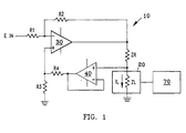
- a circuit diagram in accordance with the present invention is shown.
- This circuit embodies a modified constant current source 10 which supplies an unvarying load current I L .
- the circuit 10 includes an operational amplifier 30 with its inverting input connected to a resistance R 1 through which a reference voltage, E IN , is provided.
- the inverting input of the amplifier 30 is also connected to a first end of a resistance R 2 which is in turn connected to the output of the amplifier 30 at its second end.
- the output of amplifier 30 and second end of the resistance R 2 are also connected to a first end of an impedance Z R .
- the non-inverting input of the amplifier 30 is connected through a resistance R 3 to ground and to a first end of a feedback resistance R 4 .
- the second end of the feedback resistance R 4 is connected to the output and inverting input of another operational amplifier 40, which acts as a unity gain amplifier in this setting.
- the non-inverting input of the amplifier 40 is connected to a second end of the impedance Z R and to sensor 20.
- the sensor 20 is represented as a sensor/material impedance Z L which represents the combined impedance of the sensor structure and the material under test.
- the sensor 20, at its second end, is connected to ground.
- the mechanism 70 can be a microcomputer configured to output an actual density reading of the paving material based on an inputted reading from sensor 20.
- a given shaped and sized sensor would be calibrated for a specific paving material and the paving material being used could be chosen on the computer, e.g. from a menu of paving materials.
- the reference voltage E IN can take a variety of forms but is preferably in the range of 50 Hertz (Hz) to 50 kHz sine wave at 14V AC, most preferably at 2kHz.
- the transfer function for the constant current source of Fig. 1 is as follows:
- the impedance of the material Z L will be much greater than R 2 (Z L >>R 2 ).
- the load must be isolated from the feedback circuit. This is accomplished by the unity gain amplifier 40 between the feedback resistor R 4 and sensor 20.
- the circuit then operates as a constant current source as long as E IN , R 2 , R 1 and Z R are maintained constant and the sensor/material impedance Z L does not cause the circuit to exceed its voltage limits.
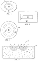
- Fig. 4 shows an exemplary structure of the sensor 20.
- the sensor 20 is in the form of a guarded circuit, i.e. guarded capacitor, including: an active inner element 26 surrounded by an intermediate guard element 28 which is surrounded by an outer element 27.
- Each of the elements is constructed of any conducting material, but is most preferably made of copper, aluminum or steel. The elements are held together and insulated from each other by an epoxy. The provision of the sensor as a guarded capacitor promotes accuracy in that determinations are not subject to stray capacitance.
- additional elements e.g., element 29 as shown in Figs. 6 and 8, surrounding those described above, and structured in similar fashion as those above, may be used to normalize the parameters of the device.
- additional elements are advantageous to make the electrical field more uniform or compensate for other parameters that may interfere with a measurement, e.g., moisture, temperature or the standoff distance from the material.
- the capacitance caused by the air gap between the sensor and paving material can adversely affect the measurement if not rectified.
- an additional element 29 is added to the sensor to attain a corrective signal proportional to the air gap.
- the present invention resonates an overall capacitance value from the additional element 29 with a known value of inductance and measures the resulting frequency.
- an RC oscillator as will be described hereafter, may be used to acquire the resulting frequency. With either method, the resulting frequency is inversely proportional to the value of the air gap capacitance and, accordingly, can be used to correct the overall capacitance reading instantaneously with any change in the standoff distance.
- an RC oscillator that can attain the correction factor above.
- One such way is to arrange for a fixed voltage to be applied to the RC network that contains a fixed resistor and the effected capacitance. This voltage is applied at a uniform repetition rate. When the voltage is applied, the capacitor will begin to discharge. After a fixed time, the process is repeated. Since the charging rate is a function of the capacitance value, the resistor is fixed, this arrangement will produce a constant frequency, variable pulse width waveform or, in other words, a pulse width modulation. This type of waveform can be converted to a DC voltage that is proportional to the size of the gap by passing the waveform through a low pass filter.
- Another arrangement with an RC network is to construct the circuit so that the RC combination determines the frequency of oscillation.
- the frequency will be a function of the capacitance value if the resistor value is fixed.
- the frequency will be proportional to the size of the gap and can be used directly in a digital form or can be converted to a DC voltage by commonly used techniques.
- variable frequency detector 80 for correcting for the standoff distance from the material.
- the variable frequency detector 80 includes a control circuit 82, an up/down counter 84, an oscillator 86, and a display 88.
- control circuit 82 resets the up/down counter 84 via a reset input 90, sets switches SW1, SW2, and SW3, to position 2, sets the up/down counter 84 to count up, and initiates counting. This produces an electric field E1 in the material. The frequency is counted for a predetermined time as determined by the control circuit 82.
- the control circuit 82 stops the count, sets switches SW1, SW2, and SW3, to position 1, sets the up/down counter 84 to count down, and initiates counting. This produces an electric field E2 in the material. Again, the frequency is counted for a predetermined time as determined by the control circuit 82.
- E2 Since the path length of E2 is shorter than E1, it has a higher capacitance and produces a lower frequency. This frequency is subtracted from the previous frequency value since the up/down counter 84 is now counting down.
- the control circuit 82 stops the count, transfers the difference between the two frequency values to the display 88 via output 92, and repeats the switching cycle.
- the difference between the two frequencies is proportional to the dielectric properties of the asphalt and can be related to the asphalt density.
- an additional element 29 can be added to make corrections for moisture.
- paving material moisture correction is more difficult to attain because the presence of moisture can manifest itself in many ways, e.g., as an energy dissipation factor or a change in dielectric constant.
- the present invention uses a sinusoidal source, such as the above described constant current source, to treat the moisture capacitance unknown as a complex impedance.
- the present invention measures the resultant quadrature and in-phase components of the resultant waveform.
- the quadrature component is proportional to the dielectric of the paving material but, the in-phase component is a measure of the loss component or moisture content. Accordingly, the overall reading can be corrected for moisture content.
- Figs. 4-6 illustrative shapes for the sensor are shown.
- Fig. 4 shows an elliptical shape
- Fig. 5 shows a rectangular shape
- Fig. 6 shows a circular shape.
- Figs. 4-6 show the sensor 20 in three preferred shapes, the sensor can take a variety of alternative shapes.
- the embodiments shown are fixed in nature, it is also envisioned to provide a sensor with an adjustable shape.
- the adjustability of the shape and the size of the sensor 20 is a significant advantage to the present invention in that changing the shape and size of the sensor dictates the depth of penetration and area of the signal and, accordingly, the volume of the measurement field. Furthermore, changing the shape and size of the sensor 20 allows for a variation of the shape of the area tested and the sensitivity.
- the capability to vary these features is important because a user can now adjust the determination to meet precise requirements and gain more accuracy. For instance, being able to accurately control the depth of penetration prevents imprecise determinations when the signal penetrates through a new lift coat into the underlying surface. Sensing of the underlying surface not only being unnecessary but also disruptive to an accurate density determinations of the new lift coat because the underlying surface may, and most likely is, already highly compacted by vehicle travel over it. Similarly, for example, when a user wishes to determine density at a seam between two new lift coats, he can now use, for instance, a long rectangular sensor to assure accurate sensing along the seam.
- the active element 26 emits an electrical signal into the paving material 50 to be used to determine the density of the paving material based on the effect on the sensor capacitance.
- the outer element 27 receives this signal from the paving material, the signal having been altered by the dielectric characteristics of the material.
- the intermediate element 28 is at the same potential as the active element 26 but the current flowing therethrough is not the same as that flowing through the active element 26 (I L ).
- the present invention is capable of determining paving material density in terms of: 1) variations in paving material density across a measurement area, and 2) actual density values.
- the capacitive voltage in the constant current source 10 created by the dielectric characteristics of the paving material and detected by the sensor 20 is measured. Accordingly, variations in the voltage are used to determine density of the paving material in terms of density variations as the sensor passes over the paving material.
- a calibration of a given sensor at a given operational setting with regard to specific types of paving material at known compaction densities is provided.
- density measurements of the given sensor can be used to determine an actual density of a paving material in the field.
- a mechanism 70 could be used to output the actual densities based on sensor input.
- a calibration can be provided of a set of sensors with a variety of shapes and sizes so that their respective depths of penetration, area and shape of measurement, and sensitivity can be pre-determined for a given type of paving material.
- the present invention can accommodate corrections of density measurement effecting parameters, e.g., standoff distance and moisture, through the use of additional elements 29 on the sensor.
- Figure 3 illustrates operation of a smaller sized sensor 20 which allows the depth of penetration to be reduced to D2 as opposed to the depth D1 shown in Fig. 2.
- the sensor 20 can operate in contact with the paving material or out of contact with the paving material 50.
- the provision of the constant current source enables the pavement density indicator to detect material density with accuracy.
- the constant current source also provides a stable system in that it is not alterable by environmental forces, e.g., electromagnetic interference or temperature. Accordingly, the potential for mismeasurement is reduced. Furthermore, the system in accordance with the present invention allows for instantaneous and continuous determinations which greatly reduces paving time.
- a constant current source is not the only way to determine the variations in sensor capacitance.
- Other alternative methods include: using fixed sinusoidal current and measuring voltage across the sensor; using fixed sinusoidal voltage and measuring current into the sensor; charging the sensor for a fixed time with a fixed current and measuring voltage; charging the sensor with a fixed current and measuring the time to reach a certain voltage; resonating the sensor with an inductor and determining frequency for a set resonant condition (e.g., ratio of sensor voltage to applied voltage); applying a fixed charge through a high impedance coupling and observing voltage output variation on sensor terminals; and applying a fixed charge and observing voltage output variations on sensor terminals.
- a set resonant condition e.g., ratio of sensor voltage to applied voltage
- the selection of the method of capacitance measurement is dependent on, for example, capacitance level being measured, percentage of variation expected, resolution required, cable length, response desired (e.g., dynamic or static), sensor operative temperature, sensor configuration (e.g., single ended, half bridge, full bridge), and costs. Accordingly, other methods of measuring the capacitance are possible within the scope of the present invention.
Abstract
Description
- The present invention relates generally to paving equipment. More particularly, the present invention relates to a paving material density indicator and method for determining density of paving material by providing a sensor with a shape and size configured to have an electrical field with at least one of a controlled depth of penetration, controlled area, controlled shape, and controlled volume.
- During paving, paving material is usually laid at about 75% of acceptable compaction. However, during subsequent compaction it is highly advantageous to assure that the paving material is compacted to as close to total acceptable compaction as possible. Attaining total acceptable compaction assures the lack of variations in the material, such as air voids, that can create potential defects in the paving material. Unfortunately, the level of compaction is not readily apparent to the naked eye. In order to address this problem, measurement of dielectric properties of paving material is known to be very useful for determining material density, a key indicator of compaction level.
- However, due to pavement laying machines used today becoming more adept at laying thinner pavement lifts, it has become necessary to have a reliable and convenient density determining device capable of measurement at differing depths, areas, shapes, and volumes of the pavement. Additionally, it has become necessary to have a density determining device which is faster than those available. Heretofore, no adequate paving material sensor capable of addressing the above problems has been devised. Accordingly, the present invention addresses a long felt need in the art.
- One pavement density indicator device is that of Blackwell, U.S. Patent No. 3,784,905. Blackwell's device measures dielectric properties of the asphalt which is representative of the change in density in the asphalt. The device to Blackwell has many disadvantages. For example, in order to obtain a reading, the Blackwell device must be moved at extremely slow speeds across the material being tested and, accordingly, requires an extended time period to provide a determination. The Blackwell device, due to its excessive weight, also requires a large sled frame (contact area) to be dragged across the pavement surface. Another disadvantage is limited adjustability of the depth of measurement of the device caused by the given set of electrodes only being able to vary the depth of measurement by changing the height of the electrodes.
- In another apparatus, a nuclear source is used to determine density of pavement material. This device has a variety of obvious drawbacks. For instance, the device requires a licensed operator and a radiation shield (e.g., a lead enclosure) Furthermore, the device is non-adjustable for area and depth, time consuming in use, and heavy, and incapable of use at high temperatures. The device is also very expensive.
- Another disadvantage of the related art devices lies in their inability to adjust depth of measuring for variations in depth of pavement (e.g., when a new layer of pavement, called a lift, has been laid). When the related art devices are used to determine the density of a new layer of pavement, the measurement may go beyond the layer of new pavement and into the material below, hence, providing an inaccurate density indication. Similarly, the related art devices may not sense far enough into the new layer, e.g., where a dip has been filled, to assure a constant compaction level within the pavement lift.
- Another disadvantage of the related art is their inability to vary the shape and area of the sensing area. Altering the shape and area of the sensor is advantageous for determining the density in particular pavement attributes, e.g., dips, seams, odd shaped patches, etc.
- Other devices, such as that of Harris, U.S. Patent No. 3,400,331, incorporated herein by reference, have been used to detect the presence and dimensions of an object. However, Harris is incapable of detecting the density of the object. Furthermore, the Harris device requires that the sensor head remain as small as possible, a disadvantage to unlimited size and shape measurement.
- It is a feature of this invention to overcome the above-listed disadvantages in the related art. Accordingly, the present invention is a paving material density sensor, the sensor having a shape and size configured to generate an electrical field with at least one of a controlled depth of penetration, controlled area, controlled shape, and controlled volume. The sensor subjects the material to an electrical field and the return signal obtained is used to measure the dielectric characteristics of the material as the latter effects the sensor capacitance. The effect on sensor capacitance is then used to determine density variations of the paving material. Since the depth, area, sensitivity, volume and shape of the determination can be changed, the present invention is more adjustable. As a result of the additional adjustability, the accuracy is increased relative to the related art devices.
- Another advantage of the present invention is that it is very lightweight and can be carried by hand. A further advantage of the present invention is its ability to give instantaneous and accurate readings of variations in the material's density thereby reducing paving time since paving does not have to stop to provide a measurement. Furthermore, since the depth and area are selectable, a volume of the measured field is also adjustable. The sensor of the present invention is also configured to be in contact or non-contact with the pavement material during use and can correct the reading for varying standoff distances from the paving material. Another advantage of the present invention is that the sensor is provided as a guarded circuit for protecting measurements from stray capacitance.
- The invention is also a set of density sensors as described above.
- The invention is also a paving material density indicator having: a sensor having a shape and size to generate an electrical field with at least one of a controlled depth of penetration, controlled area, controlled shape, and controlled volume, and a circuit operatively coupled to the sensor to indicate the density of the paving material based on the effect on sensor capacitance from the electrical field. The circuit is preferably provided as a constant current source to provide a stable circuit and, hence, promote accuracy without being subject to the environmental characteristics that plague some of the related art.
- Furthermore, the invention is a method for determining density of paving material including the steps of: 1) selecting a shape and size of a sensor to generate an electrical field having at least one of a controlled depth, controlled area, controlled shape and controlled volume; 2) generating the electrical field proximate the paving material; and 3) determining the density of the paving material from the effect on sensor capacitance due to the electrical field.
- The foregoing and other features and advantages of the invention will be apparent from the following more particular description of preferred embodiments of the invention.
- The preferred embodiments of this invention will be described in detail, with reference to the following figures, wherein like designations denote like elements, and wherein:
- Fig. 1 shows a circuit diagram of the material density indicator in accordance with the present invention;
- Fig. 2 shows a cross-sectional view of a material density indicator in accordance with a first embodiment of the present invention;
- Fig. 3 shows a cross-sectional view of a material density indicator in accordance with a second embodiment of the present invention;
- Fig. 4 shows a sensor in accordance with a first embodiment of the present invention;
- Fig. 5 shows a sensor in accordance with a second embodiment of the present invention;
- Fig. 6 shows a sensor in accordance with a third embodiment of the present invention;
- Fig. 7 shows a cross-sectional view of a material density indicator in accordance with a third embodiment of the present invention; and
- Fig. 8 shows a schematic view of a material density indicator in accordance with a fourth embodiment of the present invention.
-
- While the preferred embodiments will be described in conjunction with the paving environment, one with ordinary skill in the art should understand that the material density indicator in accordance with the present invention may be applied in a variety of material density determining settings. For example, it is contemplated that the present invention may have applicability with soil or cement as well as paving material.
- In Fig. 1, a circuit diagram in accordance with the present invention is shown. This circuit embodies a modified constant
current source 10 which supplies an unvarying load current IL. Thecircuit 10 includes anoperational amplifier 30 with its inverting input connected to a resistance R1 through which a reference voltage, EIN, is provided. The inverting input of theamplifier 30 is also connected to a first end of a resistance R2 which is in turn connected to the output of theamplifier 30 at its second end. The output ofamplifier 30 and second end of the resistance R2 are also connected to a first end of an impedance ZR. The non-inverting input of theamplifier 30 is connected through a resistance R3 to ground and to a first end of a feedback resistance R4. The second end of the feedback resistance R4 is connected to the output and inverting input of anotheroperational amplifier 40, which acts as a unity gain amplifier in this setting. The non-inverting input of theamplifier 40 is connected to a second end of the impedance ZR and tosensor 20. - The
sensor 20 is represented as a sensor/material impedance ZL which represents the combined impedance of the sensor structure and the material under test. Thesensor 20, at its second end, is connected to ground. Furthermore, it is contemplated to provide amechanism 70 for calibration of the sensor for particular paving materials. For instance, themechanism 70 can be a microcomputer configured to output an actual density reading of the paving material based on an inputted reading fromsensor 20. In this regard, a given shaped and sized sensor would be calibrated for a specific paving material and the paving material being used could be chosen on the computer, e.g. from a menu of paving materials. - In operation, the reference voltage EIN can take a variety of forms but is preferably in the range of 50 Hertz (Hz) to 50 kHz sine wave at 14V AC, most preferably at 2kHz. The transfer function for the constant current source of Fig. 1 is as follows:

- In operation, the impedance of the material ZL will be much greater than R2 (ZL>>R2). Under these conditions, to maintain the load current constant, the load must be isolated from the feedback circuit. This is accomplished by the
unity gain amplifier 40 between the feedback resistor R4 andsensor 20. The circuit then operates as a constant current source as long as EIN, R2, R1 and ZR are maintained constant and the sensor/material impedance ZL does not cause the circuit to exceed its voltage limits. - Fig. 4 shows an exemplary structure of the
sensor 20. Thesensor 20 is in the form of a guarded circuit, i.e. guarded capacitor, including: an activeinner element 26 surrounded by anintermediate guard element 28 which is surrounded by anouter element 27. Each of the elements is constructed of any conducting material, but is most preferably made of copper, aluminum or steel. The elements are held together and insulated from each other by an epoxy. The provision of the sensor as a guarded capacitor promotes accuracy in that determinations are not subject to stray capacitance. - Furthermore, if necessary, additional elements, e.g.,
element 29 as shown in Figs. 6 and 8, surrounding those described above, and structured in similar fashion as those above, may be used to normalize the parameters of the device. For instance, additional elements are advantageous to make the electrical field more uniform or compensate for other parameters that may interfere with a measurement, e.g., moisture, temperature or the standoff distance from the material. - In terms of the standoff distance from the material, the capacitance caused by the air gap between the sensor and paving material can adversely affect the measurement if not rectified. To remedy this problem, an
additional element 29 is added to the sensor to attain a corrective signal proportional to the air gap. In order to acquire this corrective signal, as shown in Fig. 8, the present invention resonates an overall capacitance value from theadditional element 29 with a known value of inductance and measures the resulting frequency. As an alternative, an RC oscillator, as will be described hereafter, may be used to acquire the resulting frequency. With either method, the resulting frequency is inversely proportional to the value of the air gap capacitance and, accordingly, can be used to correct the overall capacitance reading instantaneously with any change in the standoff distance. - There are a variety of ways to construct an RC oscillator that can attain the correction factor above. One such way is to arrange for a fixed voltage to be applied to the RC network that contains a fixed resistor and the effected capacitance. This voltage is applied at a uniform repetition rate. When the voltage is applied, the capacitor will begin to discharge. After a fixed time, the process is repeated. Since the charging rate is a function of the capacitance value, the resistor is fixed, this arrangement will produce a constant frequency, variable pulse width waveform or, in other words, a pulse width modulation. This type of waveform can be converted to a DC voltage that is proportional to the size of the gap by passing the waveform through a low pass filter.
- Another arrangement with an RC network is to construct the circuit so that the RC combination determines the frequency of oscillation. Under these conditions, the frequency will be a function of the capacitance value if the resistor value is fixed. The frequency will be proportional to the size of the gap and can be used directly in a digital form or can be converted to a DC voltage by commonly used techniques.
- Referring to FIG. 8, there is illustrated a
variable frequency detector 80 for correcting for the standoff distance from the material. Thevariable frequency detector 80 includes acontrol circuit 82, an up/downcounter 84, anoscillator 86, and adisplay 88. - In operation, the
control circuit 82 resets the up/down counter 84 via areset input 90, sets switches SW1, SW2, and SW3, toposition 2, sets the up/down counter 84 to count up, and initiates counting. This produces an electric field E1 in the material. The frequency is counted for a predetermined time as determined by thecontrol circuit 82. - When the predetermined time has elapsed, the
control circuit 82 stops the count, sets switches SW1, SW2, and SW3, toposition 1, sets the up/down counter 84 to count down, and initiates counting. This produces an electric field E2 in the material. Again, the frequency is counted for a predetermined time as determined by thecontrol circuit 82. - Since the path length of E2 is shorter than E1, it has a higher capacitance and produces a lower frequency. This frequency is subtracted from the previous frequency value since the up/down
counter 84 is now counting down. - When the predetermined time has elapsed, the
control circuit 82 stops the count, transfers the difference between the two frequency values to thedisplay 88 viaoutput 92, and repeats the switching cycle. The difference between the two frequencies is proportional to the dielectric properties of the asphalt and can be related to the asphalt density. - Similarly to the above gap size correction, an
additional element 29 can be added to make corrections for moisture. However, paving material moisture correction is more difficult to attain because the presence of moisture can manifest itself in many ways, e.g., as an energy dissipation factor or a change in dielectric constant. In order to attain a moisture correction, the present invention uses a sinusoidal source, such as the above described constant current source, to treat the moisture capacitance unknown as a complex impedance. The present invention then measures the resultant quadrature and in-phase components of the resultant waveform. The quadrature component is proportional to the dielectric of the paving material but, the in-phase component is a measure of the loss component or moisture content. Accordingly, the overall reading can be corrected for moisture content. - Referring to Figs. 4-6, illustrative shapes for the sensor are shown. Fig. 4 shows an elliptical shape; Fig. 5 shows a rectangular shape; and Fig. 6 shows a circular shape. Although, Figs. 4-6 show the
sensor 20 in three preferred shapes, the sensor can take a variety of alternative shapes. Furthermore, although the embodiments shown are fixed in nature, it is also envisioned to provide a sensor with an adjustable shape. - The adjustability of the shape and the size of the
sensor 20 is a significant advantage to the present invention in that changing the shape and size of the sensor dictates the depth of penetration and area of the signal and, accordingly, the volume of the measurement field. Furthermore, changing the shape and size of thesensor 20 allows for a variation of the shape of the area tested and the sensitivity. - The capability to vary these features is important because a user can now adjust the determination to meet precise requirements and gain more accuracy. For instance, being able to accurately control the depth of penetration prevents imprecise determinations when the signal penetrates through a new lift coat into the underlying surface. Sensing of the underlying surface not only being unnecessary but also disruptive to an accurate density determinations of the new lift coat because the underlying surface may, and most likely is, already highly compacted by vehicle travel over it. Similarly, for example, when a user wishes to determine density at a seam between two new lift coats, he can now use, for instance, a long rectangular sensor to assure accurate sensing along the seam.
- In operation, as shown in Figs. 2, 3 and 7, the
active element 26 emits an electrical signal into the pavingmaterial 50 to be used to determine the density of the paving material based on the effect on the sensor capacitance. Theouter element 27 then receives this signal from the paving material, the signal having been altered by the dielectric characteristics of the material. During this time, theintermediate element 28 is at the same potential as theactive element 26 but the current flowing therethrough is not the same as that flowing through the active element 26 (IL). - The present invention is capable of determining paving material density in terms of: 1) variations in paving material density across a measurement area, and 2) actual density values. In order to determine the density of the paving material in terms of variations in density, the capacitive voltage in the constant
current source 10 created by the dielectric characteristics of the paving material and detected by thesensor 20 is measured. Accordingly, variations in the voltage are used to determine density of the paving material in terms of density variations as the sensor passes over the paving material. - In order to determine the density in terms of actual density values of the paving material, e.g., 5 g/cm3, a calibration of a given sensor at a given operational setting with regard to specific types of paving material at known compaction densities is provided. As a result, density measurements of the given sensor can be used to determine an actual density of a paving material in the field. As noted earlier, a
mechanism 70 could be used to output the actual densities based on sensor input. Furthermore, a calibration can be provided of a set of sensors with a variety of shapes and sizes so that their respective depths of penetration, area and shape of measurement, and sensitivity can be pre-determined for a given type of paving material. Once one or both of the above-described calibrations has been conducted, sets of differently shaped and sized sensors can be packaged for use with given types of paving material, e.g., asphalt. Furthermore, themechanism 70 may be adjusted to accommodate all of these various sensors. - In addition to the above density measurements, as explained earlier, the present invention can accommodate corrections of density measurement effecting parameters, e.g., standoff distance and moisture, through the use of
additional elements 29 on the sensor. - Figure 3 illustrates operation of a smaller
sized sensor 20 which allows the depth of penetration to be reduced to D2 as opposed to the depth D1 shown in Fig. 2. Of note, as illustrated by comparing Figs. 2 and 3 with Fig. 7, thesensor 20 can operate in contact with the paving material or out of contact with the pavingmaterial 50. - The provision of the constant current source enables the pavement density indicator to detect material density with accuracy. The constant current source also provides a stable system in that it is not alterable by environmental forces, e.g., electromagnetic interference or temperature. Accordingly, the potential for mismeasurement is reduced. Furthermore, the system in accordance with the present invention allows for instantaneous and continuous determinations which greatly reduces paving time.
- While this invention has been described in conjunction with the specific embodiments outlined above, it is evident that many alternatives, modifications and variations will be apparent to those skilled in the art. Accordingly, the preferred embodiments of the invention as set forth above are intended to be illustrative, not limiting. Various changes may be made without departing from the spirit and scope of the invention as defined in the following claims.
- For example, it should be noted that the use of a constant current source is not the only way to determine the variations in sensor capacitance. Other alternative methods include: using fixed sinusoidal current and measuring voltage across the sensor; using fixed sinusoidal voltage and measuring current into the sensor; charging the sensor for a fixed time with a fixed current and measuring voltage; charging the sensor with a fixed current and measuring the time to reach a certain voltage; resonating the sensor with an inductor and determining frequency for a set resonant condition (e.g., ratio of sensor voltage to applied voltage); applying a fixed charge through a high impedance coupling and observing voltage output variation on sensor terminals; and applying a fixed charge and observing voltage output variations on sensor terminals. The selection of the method of capacitance measurement is dependent on, for example, capacitance level being measured, percentage of variation expected, resolution required, cable length, response desired (e.g., dynamic or static), sensor operative temperature, sensor configuration (e.g., single ended, half bridge, full bridge), and costs. Accordingly, other methods of measuring the capacitance are possible within the scope of the present invention.
Claims (27)
- An apparatus comprising:a paving material density sensor, the sensor having a shape and size configured to generate an electrical field with at least one of a controlled depth of penetration, controlled area, controlled shape, and controlled volume.
- The apparatus of claim 1, wherein the sensor is configured to be in contact or non-contact with the paving material during use.
- The apparatus of claim 1, wherein the sensor is a guarded circuit for protecting measurements from stray capacitance.
- The apparatus of claim 1, further comprising a constant current source operatively coupled to the sensor to measure the effect on sensor capacitance.
- The apparatus of claim 1, wherein the sensor includes at least a first, second and third element, the elements being positioned one inside of another.
- The apparatus of claim 1, wherein the sensor is a shape selected from the group consisting of circular, elliptical, and polygonal.
- The apparatus of claim 1, wherein the paving material is one of asphalt and soil.
- The apparatus of claim 7, wherein the sensor is to be in contact or non-contact with the paving material during use.
- The apparatus of claim 1, further including means for calibrating the sensor according to the paving material.
- A paving material density indicator comprising:a sensor having a shape and size configured to generate an electrical field with at least one of a controlled depth of penetration, controlled area, controlled shape, and controlled volume; anda circuit operatively coupled to the sensor to indicate the density of the paving material based on the effect on sensor capacitance from the electrical field.
- The paving material density indicator of claim 10, wherein the circuit is a constant current source.
- The paving material density indicator of claim 11, wherein the circuit has a frequency in the range of 50 Hz to 50 kHz.
- The paving material density indicator of claim 12, wherein the frequency is approximately 2 kHz.
- The paving material density indicator of claim 11, wherein the constant current source includes a unity gain amplifier.
- The paving material density indicator of claim 11, wherein the electrical field is used by the constant current source to determine the density of the paving material.
- The paving material density indicator of claim 10, wherein the sensor includes at least a first, second and third element, the elements being positioned one inside of another.
- The paving material density indicator of claim 10, wherein the sensor has a shape selected from the group consisting of circular, elliptical, and polygonal.
- The paving material density indicator of claim 10, wherein the paving material is one of asphalt and soil.
- The paving material density indicator of claim 10, wherein the sensor is in contact or non-contact with the paving material during use.
- The paving material density indicator of claim 10, further including a means for determining a distance of the sensor from the paving material and correcting the paving material density indication accordingly.
- The paving material density indicator of claim 10, further including a means for determining moisture content of the paving material and correcting the paving material density indication accordingly.
- A method for determining density of paving material comprising the steps of:selecting a shape and size of a sensor to generate an electrical field having at least one of a controlled depth, controlled area, controlled shape and controlled volume;generating the electrical field proximate the paving material; anddetermining the density of the paving material from the effect on sensor capacitance due to the electrical field.
- The method of claim 22, wherein measuring the effect on sensor capacitance includes using a constant current source.
- The method of claim 22, further including the step of calibrating the selected sensor with regard to paving material of known density so that actual density can be measured accurately when used.
- The method of claim 22, further including the step of calibrating a plurality of sensors to determine their respective measuring depths, area, shape and sensitivity for a given paving material.
- The method of claim 22, wherein the step of determining the density of paving material includes correcting the determination of density for at least one of a standoff distance of the sensor from the paving material and moisture content of the paving material.
- A paving material density indicator device comprising:a set of density sensors, each sensor having a shape and size selected to determine density of the paving material to at least one of a selected depth, area, sensitivity, and shape.
Applications Claiming Priority (2)
| Application Number | Priority Date | Filing Date | Title |
|---|---|---|---|
| US901437 | 1992-06-19 | ||
| US08/901,437 US5900736A (en) | 1997-07-28 | 1997-07-28 | Paving material density indicator and method using capacitance |
Publications (2)
| Publication Number | Publication Date |
|---|---|
| EP0895081A2 true EP0895081A2 (en) | 1999-02-03 |
| EP0895081A3 EP0895081A3 (en) | 2000-10-11 |
Family
ID=25414190
Family Applications (1)
| Application Number | Title | Priority Date | Filing Date |
|---|---|---|---|
| EP98113897A Withdrawn EP0895081A3 (en) | 1997-07-28 | 1998-07-24 | Paving material density indicator and method using capacitance |
Country Status (2)
| Country | Link |
|---|---|
| US (1) | US5900736A (en) |
| EP (1) | EP0895081A3 (en) |
Cited By (1)
| Publication number | Priority date | Publication date | Assignee | Title |
|---|---|---|---|---|
| EP1061361A1 (en) * | 1999-05-27 | 2000-12-20 | CEO Centro di Eccellenza Optronica | Device and method for capacitively detecting defects in wood |
Families Citing this family (35)
| Publication number | Priority date | Publication date | Assignee | Title |
|---|---|---|---|---|
| US6380747B1 (en) * | 1998-05-12 | 2002-04-30 | Jentek Sensors, Inc. | Methods for processing, optimization, calibration and display of measured dielectrometry signals using property estimation grids |
| AU5723300A (en) * | 1999-05-19 | 2000-12-05 | Ingersoll-Rand Company | Temperature sensing for controlling paving and compaction operations |
| US6452405B1 (en) * | 1999-09-17 | 2002-09-17 | Delphi Technologies, Inc. | Method and apparatus for calibrating a current sensing system |
| US6414497B1 (en) | 2000-05-04 | 2002-07-02 | Transtech Systems, Inc. | Paving material analyzer system and method |
| US6803771B2 (en) | 2000-05-04 | 2004-10-12 | Transtech Systems, Inc. | Paving material analyzer system and method |
| US7034695B2 (en) | 2000-12-26 | 2006-04-25 | Robert Ernest Troxler | Large area position/proximity correction device with alarms using (D)GPS technology |
| US7848905B2 (en) * | 2000-12-26 | 2010-12-07 | Troxler Electronic Laboratories, Inc. | Methods, systems, and computer program products for locating and tracking objects |
| US6915216B2 (en) | 2002-10-11 | 2005-07-05 | Troxler Electronic Laboratories, Inc. | Measurement device incorporating a locating device and a portable handheld computer device and associated apparatus, system and method |
| US6400161B1 (en) | 2001-05-23 | 2002-06-04 | Donald Joseph Geisel | Material segregation and density analyzing apparatus and method |
| US6577141B2 (en) * | 2001-06-13 | 2003-06-10 | Sauer-Danfoss, Inc. | System and method for capacitance sensing of pavement density |
| CN1280635C (en) * | 2001-07-16 | 2006-10-18 | 因泰斯特Ip公司 | Test head docking system and method |
| CN100497830C (en) * | 2001-09-19 | 2009-06-10 | 英格索尔-兰德公司 | System for measuring material properties from a moving construction vehicle |
| ITTO20020556A1 (en) * | 2002-06-26 | 2003-12-29 | Fiat Ricerche | METHOD OF DETECTION OF THE DEGREE OF COMPACTNESS OF GRANULAR MATERIALS, AND RELATIVE SENSOR FOR SUCH DETECTION |
| US6963205B2 (en) | 2002-08-21 | 2005-11-08 | Lundstrom John W | Electrically measuring soil dry density |
| CN1981190B (en) * | 2003-10-24 | 2014-04-16 | 特罗克斯勒电子实验有限公司 | Pavement material microwave density measurement methods and apparatuses |
| US7219024B2 (en) * | 2004-05-26 | 2007-05-15 | Transtech Systems, Inc. | Material analysis including density and moisture content determinations |
| US8299808B2 (en) | 2005-03-18 | 2012-10-30 | Troxler Electronic Laboratories Inc. | Apparatuses and systems for density gauge calibration and reference emulation |
| US7705614B2 (en) * | 2005-03-18 | 2010-04-27 | Troxler Electronic Laboratories, Inc. | Apparatuses and systems for density gauge reference emulation |
| US7581446B2 (en) | 2005-08-30 | 2009-09-01 | Troxler Electronic Laboratories, Inc. | Methods, systems, and computer program products for determining a property of construction material |
| US7591608B2 (en) * | 2006-06-29 | 2009-09-22 | Hall David R | Checking density while compacting |
| US7584060B2 (en) * | 2007-06-27 | 2009-09-01 | The United States Of America As Represented By The Secretary Of The Navy | Inverse method to calculate material properties using an insertion loss test |
| US7590495B2 (en) * | 2007-07-02 | 2009-09-15 | The United States Of America As Represented By The Secretary Of The Navy | Inverse method to calculate material properties using a non-resonant technique |
| US8716650B2 (en) | 2008-01-04 | 2014-05-06 | Troxler Electronic Laboratories, Inc. | Nuclear gauges and related methods of assembly |
| US8821009B2 (en) * | 2009-12-23 | 2014-09-02 | Intel Corporation | Thermal sensors having flexible substrates and use thereof |
| US9465061B2 (en) | 2012-05-16 | 2016-10-11 | Transtech Systems, Inc. | In-process material characterization |
| DE112013006195T5 (en) * | 2012-12-24 | 2015-09-10 | Sintokogio, Ltd. | Method for detecting powder and powder detection device |
| WO2014153263A1 (en) * | 2013-03-14 | 2014-09-25 | Robert Ernest Troxler | Systems and methods for asphalt density and soil moisture measurements using ground penetrating radar |
| US9804112B2 (en) | 2013-11-20 | 2017-10-31 | Transtech Systems, Inc. | Selective characterization of material under test (MUT) with electromagnetic impedance tomography and spectroscopy |
| US9863900B2 (en) | 2014-01-28 | 2018-01-09 | Transtech Systems, Inc. | Planar sensor array for non-destructive evaluation of material using electromagnetic impedance |
| US10161893B2 (en) | 2014-08-19 | 2018-12-25 | Transtech Systems, Inc. | Characterization of material under test (MUT) with electromagnetic impedance spectroscopy |
| US10527570B2 (en) | 2016-01-12 | 2020-01-07 | Transtech Systems, Inc. | Determining location of electromagnetic impedance spectrographic analysis using electromagnetic impedance tomography |
| US10494774B2 (en) * | 2018-03-29 | 2019-12-03 | Geophysical Survey Systems, Inc. | Asphalt dielectric measurement accuracy improvement using asphalt surface temperature |
| JP6652999B1 (en) * | 2018-09-04 | 2020-02-26 | 国立大学法人東京農工大学 | Food inspection device and food inspection method |
| US11313086B2 (en) * | 2019-12-16 | 2022-04-26 | Caterpillar Paving Products Inc. | Material density measurement for paver application |
| US20210325326A1 (en) | 2020-04-16 | 2021-10-21 | Transtech Systems, Inc. | Methods, circuits and systems for obtaining impedance or dielectric measurements of a material under test |
Citations (11)
| Publication number | Priority date | Publication date | Assignee | Title |
|---|---|---|---|---|
| US3400331A (en) * | 1965-01-18 | 1968-09-03 | Pratt & Whitney Inc | Gaging device including a probe having a plurality of concentric and coextensive electrodes |
| DE1914447A1 (en) * | 1969-03-21 | 1970-06-11 | Weyl Detlef H | Electrical process for the continuous determination of the dry matter content of water-containing production goods |
| US3694742A (en) * | 1970-07-15 | 1972-09-26 | Karlis Alfredovich Bergmanis | Device for measuring permittivity of materials |
| US3761805A (en) * | 1971-06-24 | 1973-09-25 | Western Electric Co | Methods of and systems for measuring capacitance using a constant current charging technique |
| US3781672A (en) * | 1971-05-10 | 1973-12-25 | Drexelbrook Controls | Continuous condition measuring system |
| US3784905A (en) * | 1972-11-29 | 1974-01-08 | Soiltest Inc | Apparatus for determination of the density of in-place materials by measurement of their dielectric strength |
| US4560923A (en) * | 1983-11-15 | 1985-12-24 | Hanson Colin J | Moisture analyzer |
| US4817021A (en) * | 1985-01-24 | 1989-03-28 | Commonwealth Scientific And Industrial Research Organisation | Moisture and density determination |
| US4845421A (en) * | 1986-10-10 | 1989-07-04 | Mineral Control Instrumentation Ltd. | Method and apparatus for measuring the moisture content of a substance |
| JPH02196960A (en) * | 1989-01-25 | 1990-08-03 | Koden Electron Co Ltd | Measuring instrument for compaction of soil |
| US5436565A (en) * | 1992-09-14 | 1995-07-25 | The United States Of America As Represented By The Secretary Of The Navy | Non-contacting capacitance probe for dielectric cure monitoring |
Family Cites Families (26)
| Publication number | Priority date | Publication date | Assignee | Title |
|---|---|---|---|---|
| US3671857A (en) * | 1970-04-29 | 1972-06-20 | Karlis Alfredovich Bergmanis | Device for measuring permittivity of materials |
| US3882381A (en) * | 1973-11-05 | 1975-05-06 | Surface Systems | System for detecting wet and icy surface conditions |
| US3967912A (en) * | 1974-03-18 | 1976-07-06 | Parker Jimmy L | Paver feed control |
| US4099118A (en) * | 1977-07-25 | 1978-07-04 | Franklin Robert C | Electronic wall stud sensor |
| US4433286A (en) * | 1979-04-09 | 1984-02-21 | Georgetown University | Identification of materials using their complex dielectric response |
| US4389136A (en) * | 1981-01-23 | 1983-06-21 | Seaman Nuclear Corporation | Method of determining density |
| US4468610A (en) * | 1982-04-14 | 1984-08-28 | Penril Corp. | Radio frequency apparatus for measuring moisture content of materials as a function of dielectric constant |
| GB2124764B (en) * | 1982-08-03 | 1986-01-08 | Atomic Energy Authority Uk | Ice detector |
| FR2593200B1 (en) * | 1986-01-20 | 1990-03-16 | Blandin Yves | MULTI-PURPOSE FINISHER |
| US5134380A (en) * | 1986-02-10 | 1992-07-28 | Otakar Jonas | Icing detector and method |
| US4766369A (en) * | 1986-03-31 | 1988-08-23 | The United States Of America As Represented By The Administrator Of The National Aeronautics And Space Administration | Ice detector |
| US4933853A (en) * | 1988-09-28 | 1990-06-12 | Raytheon Company | Ultrasonic grade and auger control |
| US5398547A (en) * | 1989-01-10 | 1995-03-21 | Innovative Dynamics, Inc. | Apparatus for measuring ice distribution profiles |
| US4972154A (en) * | 1989-06-06 | 1990-11-20 | Metriguard, Inc | Apparatus and method for measuring wood grain angle |
| DE4022563A1 (en) * | 1990-04-11 | 1991-10-17 | Flachglas Ag | METHOD FOR CONTACTLESS MEASUREMENT OF THE ELECTRICAL RESISTANCE OF AN EXAMINATION MATERIAL |
| US5281921A (en) * | 1990-04-24 | 1994-01-25 | Novak James L | Non-contact capacitance based image sensing method and system |
| US5088854A (en) * | 1990-08-13 | 1992-02-18 | Aw-2R, Inc. | Paving joints |
| US5213442A (en) * | 1990-08-15 | 1993-05-25 | Aw-2R, Inc. | Controlled density paving and apparatus therefor |
| US5138268A (en) * | 1990-08-15 | 1992-08-11 | Steve Mulkey | Thickness measuring system for nonconducting materials |
| US5051026A (en) * | 1990-08-15 | 1991-09-24 | Aw-2R, Inc. | Controlled density paving and apparatus therefor |
| US5223796A (en) * | 1991-05-28 | 1993-06-29 | Axiomatics Corporation | Apparatus and methods for measuring the dielectric and geometric properties of materials |
| US5309110A (en) * | 1992-03-04 | 1994-05-03 | The Perkin Elmer Corporation | Differential dielectric analyzer |
| US5363051A (en) * | 1992-11-23 | 1994-11-08 | The United States Of America As Represented By The Administrator Of The National Aeronautics And Space Administration | Steering capaciflector sensor |
| US5484226A (en) * | 1994-01-18 | 1996-01-16 | Caterpillar Paving Products Inc. | Controlling apparatus for asphalt pavers |
| US5602486A (en) * | 1994-03-14 | 1997-02-11 | Sandia Corporation | Impedance sensing of flaws in non-homogenous materials |
| US5521515A (en) * | 1995-02-17 | 1996-05-28 | The United States Of America As Represented By The Administrator Of The National Aeronautics And Space Administration | Frequency scanning capaciflector for capacitively determining the material properties |
-
1997
- 1997-07-28 US US08/901,437 patent/US5900736A/en not_active Expired - Lifetime
-
1998
- 1998-07-24 EP EP98113897A patent/EP0895081A3/en not_active Withdrawn
Patent Citations (11)
| Publication number | Priority date | Publication date | Assignee | Title |
|---|---|---|---|---|
| US3400331A (en) * | 1965-01-18 | 1968-09-03 | Pratt & Whitney Inc | Gaging device including a probe having a plurality of concentric and coextensive electrodes |
| DE1914447A1 (en) * | 1969-03-21 | 1970-06-11 | Weyl Detlef H | Electrical process for the continuous determination of the dry matter content of water-containing production goods |
| US3694742A (en) * | 1970-07-15 | 1972-09-26 | Karlis Alfredovich Bergmanis | Device for measuring permittivity of materials |
| US3781672A (en) * | 1971-05-10 | 1973-12-25 | Drexelbrook Controls | Continuous condition measuring system |
| US3761805A (en) * | 1971-06-24 | 1973-09-25 | Western Electric Co | Methods of and systems for measuring capacitance using a constant current charging technique |
| US3784905A (en) * | 1972-11-29 | 1974-01-08 | Soiltest Inc | Apparatus for determination of the density of in-place materials by measurement of their dielectric strength |
| US4560923A (en) * | 1983-11-15 | 1985-12-24 | Hanson Colin J | Moisture analyzer |
| US4817021A (en) * | 1985-01-24 | 1989-03-28 | Commonwealth Scientific And Industrial Research Organisation | Moisture and density determination |
| US4845421A (en) * | 1986-10-10 | 1989-07-04 | Mineral Control Instrumentation Ltd. | Method and apparatus for measuring the moisture content of a substance |
| JPH02196960A (en) * | 1989-01-25 | 1990-08-03 | Koden Electron Co Ltd | Measuring instrument for compaction of soil |
| US5436565A (en) * | 1992-09-14 | 1995-07-25 | The United States Of America As Represented By The Secretary Of The Navy | Non-contacting capacitance probe for dielectric cure monitoring |
Non-Patent Citations (1)
| Title |
|---|
| PATENT ABSTRACTS OF JAPAN vol. 014, no. 484 (P-1120), 22 October 1990 (1990-10-22) & JP 02 196960 A (KODEN ELECTRON CO LTD;OTHERS: 01), 3 August 1990 (1990-08-03) * |
Cited By (1)
| Publication number | Priority date | Publication date | Assignee | Title |
|---|---|---|---|---|
| EP1061361A1 (en) * | 1999-05-27 | 2000-12-20 | CEO Centro di Eccellenza Optronica | Device and method for capacitively detecting defects in wood |
Also Published As
| Publication number | Publication date |
|---|---|
| US5900736A (en) | 1999-05-04 |
| EP0895081A3 (en) | 2000-10-11 |
Similar Documents
| Publication | Publication Date | Title |
|---|---|---|
| US5900736A (en) | Paving material density indicator and method using capacitance | |
| US6414497B1 (en) | Paving material analyzer system and method | |
| US6803771B2 (en) | Paving material analyzer system and method | |
| US4399404A (en) | Moisture tester with probe | |
| JP4526043B2 (en) | Measuring apparatus and measuring method for measuring dielectric properties of products, in particular humidity and / or density | |
| US3901079A (en) | Two-mode capacitive liquid level sensing system | |
| DE4333419C2 (en) | Method and device for layer thickness measurement and measuring probe for a combined layer thickness measuring device | |
| US4070612A (en) | Method and apparatus for measuring terrain resistivity | |
| JP6267651B2 (en) | System, controller and method for determining the conductance of an object | |
| US4044607A (en) | Grain moisture measurement probe | |
| US6677763B2 (en) | Material segregation, density, and moisture analyzing apparatus and method | |
| EP0514964A2 (en) | Capacitance flowmeter | |
| CA1103329A (en) | Sensor for determining level of a flowing liquid in a vessel | |
| US11585774B2 (en) | Soil moisture sensor and operating method thereof | |
| JPH08136209A (en) | Detection of geometrical position,displacement or angle of movable body and noncontact capacity-reference-position sensor | |
| US6400161B1 (en) | Material segregation and density analyzing apparatus and method | |
| US4924173A (en) | Shielded capacitance standard | |
| JPS5972205A (en) | Frequency varying method of lc oscillator for analog value detection | |
| JP2843067B2 (en) | Glass container thickness inspection machine | |
| JPH11304764A (en) | Moisture sensor | |
| US11598743B2 (en) | Soil monitoring sensor including single probe and temperature compensation and method of operating the same | |
| US3199350A (en) | Capacitance type fuel gage | |
| KR102290987B1 (en) | Soil moisture sensor and method of operation thereof | |
| KR102224169B1 (en) | Soil moisture sensor and method of operation thereof | |
| JPH02238353A (en) | Apparatus for measuring water content rate |
Legal Events
| Date | Code | Title | Description |
|---|---|---|---|
| PUAI | Public reference made under article 153(3) epc to a published international application that has entered the european phase |
Free format text: ORIGINAL CODE: 0009012 |
|
| AK | Designated contracting states |
Kind code of ref document: A2 Designated state(s): AT BE CH CY DE DK ES FI FR GB GR IE IT LI LU MC NL PT SE |
|
| AX | Request for extension of the european patent |
Free format text: AL;LT;LV;MK;RO;SI |
|
| PUAL | Search report despatched |
Free format text: ORIGINAL CODE: 0009013 |
|
| AK | Designated contracting states |
Kind code of ref document: A3 Designated state(s): AT BE CH CY DE DK ES FI FR GB GR IE IT LI LU MC NL PT SE |
|
| AX | Request for extension of the european patent |
Free format text: AL;LT;LV;MK;RO;SI |
|
| AKX | Designation fees paid | ||
| REG | Reference to a national code |
Ref country code: DE Ref legal event code: 8566 |
|
| STAA | Information on the status of an ep patent application or granted ep patent |
Free format text: STATUS: THE APPLICATION IS DEEMED TO BE WITHDRAWN |
|
| 18D | Application deemed to be withdrawn |
Effective date: 20010412 |