EP0896879B1 - Simplified ink jet head - Google Patents
Simplified ink jet head Download PDFInfo
- Publication number
- EP0896879B1 EP0896879B1 EP98203766A EP98203766A EP0896879B1 EP 0896879 B1 EP0896879 B1 EP 0896879B1 EP 98203766 A EP98203766 A EP 98203766A EP 98203766 A EP98203766 A EP 98203766A EP 0896879 B1 EP0896879 B1 EP 0896879B1
- Authority
- EP
- European Patent Office
- Prior art keywords
- ink
- plate
- ink jet
- carbon
- jet head
- Prior art date
- Legal status (The legal status is an assumption and is not a legal conclusion. Google has not performed a legal analysis and makes no representation as to the accuracy of the status listed.)
- Expired - Lifetime
Links
- OKTJSMMVPCPJKN-UHFFFAOYSA-N Carbon Chemical compound [C] OKTJSMMVPCPJKN-UHFFFAOYSA-N 0.000 claims description 55
- 229910052799 carbon Inorganic materials 0.000 claims description 44
- 239000000463 material Substances 0.000 claims description 17
- 229910002804 graphite Inorganic materials 0.000 claims description 9
- 239000010439 graphite Substances 0.000 claims description 9
- 239000012943 hotmelt Substances 0.000 claims description 6
- -1 polytetrafluoroethylene Polymers 0.000 claims description 3
- 229920001343 polytetrafluoroethylene Polymers 0.000 claims description 3
- 239000004810 polytetrafluoroethylene Substances 0.000 claims description 3
- 238000003491 array Methods 0.000 description 12
- 238000000034 method Methods 0.000 description 8
- 239000000853 adhesive Substances 0.000 description 7
- 230000001070 adhesive effect Effects 0.000 description 7
- 239000011148 porous material Substances 0.000 description 6
- 230000000712 assembly Effects 0.000 description 4
- 238000000429 assembly Methods 0.000 description 4
- 239000000919 ceramic Substances 0.000 description 4
- XAGFODPZIPBFFR-UHFFFAOYSA-N aluminium Chemical compound [Al] XAGFODPZIPBFFR-UHFFFAOYSA-N 0.000 description 3
- 239000003575 carbonaceous material Substances 0.000 description 3
- 229920001169 thermoplastic Polymers 0.000 description 3
- 239000004416 thermosoftening plastic Substances 0.000 description 3
- SSMIFVHARFVINF-UHFFFAOYSA-N 4-amino-1,8-naphthalimide Chemical compound O=C1NC(=O)C2=CC=CC3=C2C1=CC=C3N SSMIFVHARFVINF-UHFFFAOYSA-N 0.000 description 2
- 239000004593 Epoxy Substances 0.000 description 2
- 101710178630 Putative defense protein 1 Proteins 0.000 description 2
- 229920004738 ULTEM® Polymers 0.000 description 2
- 229910052782 aluminium Inorganic materials 0.000 description 2
- 230000006837 decompression Effects 0.000 description 2
- 238000005553 drilling Methods 0.000 description 2
- 238000003754 machining Methods 0.000 description 2
- 239000012528 membrane Substances 0.000 description 2
- 150000004767 nitrides Chemical class 0.000 description 2
- 239000002245 particle Substances 0.000 description 2
- 238000005086 pumping Methods 0.000 description 2
- 238000007493 shaping process Methods 0.000 description 2
- 239000011343 solid material Substances 0.000 description 2
- 229910052580 B4C Inorganic materials 0.000 description 1
- 229910052582 BN Inorganic materials 0.000 description 1
- PZNSFCLAULLKQX-UHFFFAOYSA-N Boron nitride Chemical compound N#B PZNSFCLAULLKQX-UHFFFAOYSA-N 0.000 description 1
- 229920000049 Carbon (fiber) Polymers 0.000 description 1
- YCKRFDGAMUMZLT-UHFFFAOYSA-N Fluorine atom Chemical compound [F] YCKRFDGAMUMZLT-UHFFFAOYSA-N 0.000 description 1
- 229910052581 Si3N4 Inorganic materials 0.000 description 1
- 229910000831 Steel Inorganic materials 0.000 description 1
- 239000004809 Teflon Substances 0.000 description 1
- 229920006362 Teflon® Polymers 0.000 description 1
- RTAQQCXQSZGOHL-UHFFFAOYSA-N Titanium Chemical compound [Ti] RTAQQCXQSZGOHL-UHFFFAOYSA-N 0.000 description 1
- NIXOWILDQLNWCW-UHFFFAOYSA-N acrylic acid group Chemical group C(C=C)(=O)O NIXOWILDQLNWCW-UHFFFAOYSA-N 0.000 description 1
- PNEYBMLMFCGWSK-UHFFFAOYSA-N aluminium oxide Inorganic materials [O-2].[O-2].[O-2].[Al+3].[Al+3] PNEYBMLMFCGWSK-UHFFFAOYSA-N 0.000 description 1
- 229910003481 amorphous carbon Inorganic materials 0.000 description 1
- 230000015572 biosynthetic process Effects 0.000 description 1
- INAHAJYZKVIDIZ-UHFFFAOYSA-N boron carbide Chemical compound B12B3B4C32B41 INAHAJYZKVIDIZ-UHFFFAOYSA-N 0.000 description 1
- 239000004917 carbon fiber Substances 0.000 description 1
- 238000005229 chemical vapour deposition Methods 0.000 description 1
- 239000011248 coating agent Substances 0.000 description 1
- 238000000576 coating method Methods 0.000 description 1
- 239000013078 crystal Substances 0.000 description 1
- 230000003247 decreasing effect Effects 0.000 description 1
- 230000000694 effects Effects 0.000 description 1
- 229910052731 fluorine Inorganic materials 0.000 description 1
- 239000011737 fluorine Substances 0.000 description 1
- NBVXSUQYWXRMNV-UHFFFAOYSA-N fluoromethane Chemical compound FC NBVXSUQYWXRMNV-UHFFFAOYSA-N 0.000 description 1
- 239000011521 glass Substances 0.000 description 1
- 238000000227 grinding Methods 0.000 description 1
- 238000013007 heat curing Methods 0.000 description 1
- 239000006233 lamp black Substances 0.000 description 1
- JQJCSZOEVBFDKO-UHFFFAOYSA-N lead zinc Chemical compound [Zn].[Pb] JQJCSZOEVBFDKO-UHFFFAOYSA-N 0.000 description 1
- 230000033001 locomotion Effects 0.000 description 1
- 230000007257 malfunction Effects 0.000 description 1
- 239000011159 matrix material Substances 0.000 description 1
- 229910052751 metal Inorganic materials 0.000 description 1
- 239000002184 metal Substances 0.000 description 1
- VNWKTOKETHGBQD-UHFFFAOYSA-N methane Chemical compound C VNWKTOKETHGBQD-UHFFFAOYSA-N 0.000 description 1
- NFFIWVVINABMKP-UHFFFAOYSA-N methylidynetantalum Chemical compound [Ta]#C NFFIWVVINABMKP-UHFFFAOYSA-N 0.000 description 1
- 238000005459 micromachining Methods 0.000 description 1
- 238000003801 milling Methods 0.000 description 1
- 239000000203 mixture Substances 0.000 description 1
- 238000001259 photo etching Methods 0.000 description 1
- 230000000135 prohibitive effect Effects 0.000 description 1
- 238000000518 rheometry Methods 0.000 description 1
- 229910010271 silicon carbide Inorganic materials 0.000 description 1
- HBMJWWWQQXIZIP-UHFFFAOYSA-N silicon carbide Chemical compound [Si+]#[C-] HBMJWWWQQXIZIP-UHFFFAOYSA-N 0.000 description 1
- HQVNEWCFYHHQES-UHFFFAOYSA-N silicon nitride Chemical compound N12[Si]34N5[Si]62N3[Si]51N64 HQVNEWCFYHHQES-UHFFFAOYSA-N 0.000 description 1
- 239000007921 spray Substances 0.000 description 1
- 239000010959 steel Substances 0.000 description 1
- 239000000126 substance Substances 0.000 description 1
- 239000000758 substrate Substances 0.000 description 1
- 229910003468 tantalcarbide Inorganic materials 0.000 description 1
- MZLGASXMSKOWSE-UHFFFAOYSA-N tantalum nitride Chemical compound [Ta]#N MZLGASXMSKOWSE-UHFFFAOYSA-N 0.000 description 1
- 230000008646 thermal stress Effects 0.000 description 1
- UONOETXJSWQNOL-UHFFFAOYSA-N tungsten carbide Chemical compound [W+]#[C-] UONOETXJSWQNOL-UHFFFAOYSA-N 0.000 description 1
Images


Classifications
-
- B—PERFORMING OPERATIONS; TRANSPORTING
- B41—PRINTING; LINING MACHINES; TYPEWRITERS; STAMPS
- B41J—TYPEWRITERS; SELECTIVE PRINTING MECHANISMS, i.e. MECHANISMS PRINTING OTHERWISE THAN FROM A FORME; CORRECTION OF TYPOGRAPHICAL ERRORS
- B41J2/00—Typewriters or selective printing mechanisms characterised by the printing or marking process for which they are designed
- B41J2/005—Typewriters or selective printing mechanisms characterised by the printing or marking process for which they are designed characterised by bringing liquid or particles selectively into contact with a printing material
- B41J2/01—Ink jet
- B41J2/135—Nozzles
- B41J2/14—Structure thereof only for on-demand ink jet heads
-
- B—PERFORMING OPERATIONS; TRANSPORTING
- B41—PRINTING; LINING MACHINES; TYPEWRITERS; STAMPS
- B41J—TYPEWRITERS; SELECTIVE PRINTING MECHANISMS, i.e. MECHANISMS PRINTING OTHERWISE THAN FROM A FORME; CORRECTION OF TYPOGRAPHICAL ERRORS
- B41J2/00—Typewriters or selective printing mechanisms characterised by the printing or marking process for which they are designed
- B41J2/005—Typewriters or selective printing mechanisms characterised by the printing or marking process for which they are designed characterised by bringing liquid or particles selectively into contact with a printing material
- B41J2/01—Ink jet
- B41J2/135—Nozzles
- B41J2/16—Production of nozzles
- B41J2/1607—Production of print heads with piezoelectric elements
- B41J2/1614—Production of print heads with piezoelectric elements of cantilever type
-
- B—PERFORMING OPERATIONS; TRANSPORTING
- B41—PRINTING; LINING MACHINES; TYPEWRITERS; STAMPS
- B41J—TYPEWRITERS; SELECTIVE PRINTING MECHANISMS, i.e. MECHANISMS PRINTING OTHERWISE THAN FROM A FORME; CORRECTION OF TYPOGRAPHICAL ERRORS
- B41J2/00—Typewriters or selective printing mechanisms characterised by the printing or marking process for which they are designed
- B41J2/005—Typewriters or selective printing mechanisms characterised by the printing or marking process for which they are designed characterised by bringing liquid or particles selectively into contact with a printing material
- B41J2/01—Ink jet
- B41J2/135—Nozzles
- B41J2/14—Structure thereof only for on-demand ink jet heads
- B41J2/14201—Structure of print heads with piezoelectric elements
- B41J2/14282—Structure of print heads with piezoelectric elements of cantilever type
-
- B—PERFORMING OPERATIONS; TRANSPORTING
- B41—PRINTING; LINING MACHINES; TYPEWRITERS; STAMPS
- B41J—TYPEWRITERS; SELECTIVE PRINTING MECHANISMS, i.e. MECHANISMS PRINTING OTHERWISE THAN FROM A FORME; CORRECTION OF TYPOGRAPHICAL ERRORS
- B41J2/00—Typewriters or selective printing mechanisms characterised by the printing or marking process for which they are designed
- B41J2/005—Typewriters or selective printing mechanisms characterised by the printing or marking process for which they are designed characterised by bringing liquid or particles selectively into contact with a printing material
- B41J2/01—Ink jet
- B41J2/135—Nozzles
- B41J2/145—Arrangement thereof
- B41J2/155—Arrangement thereof for line printing
-
- B—PERFORMING OPERATIONS; TRANSPORTING
- B41—PRINTING; LINING MACHINES; TYPEWRITERS; STAMPS
- B41J—TYPEWRITERS; SELECTIVE PRINTING MECHANISMS, i.e. MECHANISMS PRINTING OTHERWISE THAN FROM A FORME; CORRECTION OF TYPOGRAPHICAL ERRORS
- B41J2/00—Typewriters or selective printing mechanisms characterised by the printing or marking process for which they are designed
- B41J2/005—Typewriters or selective printing mechanisms characterised by the printing or marking process for which they are designed characterised by bringing liquid or particles selectively into contact with a printing material
- B41J2/01—Ink jet
- B41J2/135—Nozzles
- B41J2/16—Production of nozzles
- B41J2/162—Manufacturing of the nozzle plates
-
- B—PERFORMING OPERATIONS; TRANSPORTING
- B41—PRINTING; LINING MACHINES; TYPEWRITERS; STAMPS
- B41J—TYPEWRITERS; SELECTIVE PRINTING MECHANISMS, i.e. MECHANISMS PRINTING OTHERWISE THAN FROM A FORME; CORRECTION OF TYPOGRAPHICAL ERRORS
- B41J2/00—Typewriters or selective printing mechanisms characterised by the printing or marking process for which they are designed
- B41J2/005—Typewriters or selective printing mechanisms characterised by the printing or marking process for which they are designed characterised by bringing liquid or particles selectively into contact with a printing material
- B41J2/01—Ink jet
- B41J2/135—Nozzles
- B41J2/16—Production of nozzles
- B41J2/1621—Manufacturing processes
- B41J2/1623—Manufacturing processes bonding and adhesion
-
- B—PERFORMING OPERATIONS; TRANSPORTING
- B41—PRINTING; LINING MACHINES; TYPEWRITERS; STAMPS
- B41J—TYPEWRITERS; SELECTIVE PRINTING MECHANISMS, i.e. MECHANISMS PRINTING OTHERWISE THAN FROM A FORME; CORRECTION OF TYPOGRAPHICAL ERRORS
- B41J2/00—Typewriters or selective printing mechanisms characterised by the printing or marking process for which they are designed
- B41J2/005—Typewriters or selective printing mechanisms characterised by the printing or marking process for which they are designed characterised by bringing liquid or particles selectively into contact with a printing material
- B41J2/01—Ink jet
- B41J2/135—Nozzles
- B41J2/16—Production of nozzles
- B41J2/1621—Manufacturing processes
- B41J2/1626—Manufacturing processes etching
-
- B—PERFORMING OPERATIONS; TRANSPORTING
- B41—PRINTING; LINING MACHINES; TYPEWRITERS; STAMPS
- B41J—TYPEWRITERS; SELECTIVE PRINTING MECHANISMS, i.e. MECHANISMS PRINTING OTHERWISE THAN FROM A FORME; CORRECTION OF TYPOGRAPHICAL ERRORS
- B41J2/00—Typewriters or selective printing mechanisms characterised by the printing or marking process for which they are designed
- B41J2/005—Typewriters or selective printing mechanisms characterised by the printing or marking process for which they are designed characterised by bringing liquid or particles selectively into contact with a printing material
- B41J2/01—Ink jet
- B41J2/135—Nozzles
- B41J2/16—Production of nozzles
- B41J2/1621—Manufacturing processes
- B41J2/1631—Manufacturing processes photolithography
-
- B—PERFORMING OPERATIONS; TRANSPORTING
- B41—PRINTING; LINING MACHINES; TYPEWRITERS; STAMPS
- B41J—TYPEWRITERS; SELECTIVE PRINTING MECHANISMS, i.e. MECHANISMS PRINTING OTHERWISE THAN FROM A FORME; CORRECTION OF TYPOGRAPHICAL ERRORS
- B41J2/00—Typewriters or selective printing mechanisms characterised by the printing or marking process for which they are designed
- B41J2/005—Typewriters or selective printing mechanisms characterised by the printing or marking process for which they are designed characterised by bringing liquid or particles selectively into contact with a printing material
- B41J2/01—Ink jet
- B41J2/135—Nozzles
- B41J2/16—Production of nozzles
- B41J2/1621—Manufacturing processes
- B41J2/1632—Manufacturing processes machining
- B41J2/1634—Manufacturing processes machining laser machining
-
- B—PERFORMING OPERATIONS; TRANSPORTING
- B41—PRINTING; LINING MACHINES; TYPEWRITERS; STAMPS
- B41J—TYPEWRITERS; SELECTIVE PRINTING MECHANISMS, i.e. MECHANISMS PRINTING OTHERWISE THAN FROM A FORME; CORRECTION OF TYPOGRAPHICAL ERRORS
- B41J2/00—Typewriters or selective printing mechanisms characterised by the printing or marking process for which they are designed
- B41J2/005—Typewriters or selective printing mechanisms characterised by the printing or marking process for which they are designed characterised by bringing liquid or particles selectively into contact with a printing material
- B41J2/01—Ink jet
- B41J2/135—Nozzles
- B41J2/16—Production of nozzles
- B41J2/1621—Manufacturing processes
- B41J2/164—Manufacturing processes thin film formation
- B41J2/1642—Manufacturing processes thin film formation thin film formation by CVD [chemical vapor deposition]
-
- B—PERFORMING OPERATIONS; TRANSPORTING
- B41—PRINTING; LINING MACHINES; TYPEWRITERS; STAMPS
- B41J—TYPEWRITERS; SELECTIVE PRINTING MECHANISMS, i.e. MECHANISMS PRINTING OTHERWISE THAN FROM A FORME; CORRECTION OF TYPOGRAPHICAL ERRORS
- B41J2/00—Typewriters or selective printing mechanisms characterised by the printing or marking process for which they are designed
- B41J2/005—Typewriters or selective printing mechanisms characterised by the printing or marking process for which they are designed characterised by bringing liquid or particles selectively into contact with a printing material
- B41J2/01—Ink jet
- B41J2/17—Ink jet characterised by ink handling
- B41J2/175—Ink supply systems ; Circuit parts therefor
- B41J2/17563—Ink filters
-
- B—PERFORMING OPERATIONS; TRANSPORTING
- B41—PRINTING; LINING MACHINES; TYPEWRITERS; STAMPS
- B41J—TYPEWRITERS; SELECTIVE PRINTING MECHANISMS, i.e. MECHANISMS PRINTING OTHERWISE THAN FROM A FORME; CORRECTION OF TYPOGRAPHICAL ERRORS
- B41J2/00—Typewriters or selective printing mechanisms characterised by the printing or marking process for which they are designed
- B41J2/005—Typewriters or selective printing mechanisms characterised by the printing or marking process for which they are designed characterised by bringing liquid or particles selectively into contact with a printing material
- B41J2/01—Ink jet
- B41J2/17—Ink jet characterised by ink handling
- B41J2/19—Ink jet characterised by ink handling for removing air bubbles
-
- H—ELECTRICITY
- H10—SEMICONDUCTOR DEVICES; ELECTRIC SOLID-STATE DEVICES NOT OTHERWISE PROVIDED FOR
- H10N—ELECTRIC SOLID-STATE DEVICES NOT OTHERWISE PROVIDED FOR
- H10N30/00—Piezoelectric or electrostrictive devices
- H10N30/01—Manufacture or treatment
- H10N30/04—Treatments to modify a piezoelectric or electrostrictive property, e.g. polarisation characteristics, vibration characteristics or mode tuning
- H10N30/045—Treatments to modify a piezoelectric or electrostrictive property, e.g. polarisation characteristics, vibration characteristics or mode tuning by polarising
-
- B—PERFORMING OPERATIONS; TRANSPORTING
- B41—PRINTING; LINING MACHINES; TYPEWRITERS; STAMPS
- B41J—TYPEWRITERS; SELECTIVE PRINTING MECHANISMS, i.e. MECHANISMS PRINTING OTHERWISE THAN FROM A FORME; CORRECTION OF TYPOGRAPHICAL ERRORS
- B41J2/00—Typewriters or selective printing mechanisms characterised by the printing or marking process for which they are designed
- B41J2/005—Typewriters or selective printing mechanisms characterised by the printing or marking process for which they are designed characterised by bringing liquid or particles selectively into contact with a printing material
- B41J2/01—Ink jet
- B41J2/135—Nozzles
- B41J2/14—Structure thereof only for on-demand ink jet heads
- B41J2002/14362—Assembling elements of heads
-
- B—PERFORMING OPERATIONS; TRANSPORTING
- B41—PRINTING; LINING MACHINES; TYPEWRITERS; STAMPS
- B41J—TYPEWRITERS; SELECTIVE PRINTING MECHANISMS, i.e. MECHANISMS PRINTING OTHERWISE THAN FROM A FORME; CORRECTION OF TYPOGRAPHICAL ERRORS
- B41J2/00—Typewriters or selective printing mechanisms characterised by the printing or marking process for which they are designed
- B41J2/005—Typewriters or selective printing mechanisms characterised by the printing or marking process for which they are designed characterised by bringing liquid or particles selectively into contact with a printing material
- B41J2/01—Ink jet
- B41J2/135—Nozzles
- B41J2/14—Structure thereof only for on-demand ink jet heads
- B41J2002/14379—Edge shooter
-
- B—PERFORMING OPERATIONS; TRANSPORTING
- B41—PRINTING; LINING MACHINES; TYPEWRITERS; STAMPS
- B41J—TYPEWRITERS; SELECTIVE PRINTING MECHANISMS, i.e. MECHANISMS PRINTING OTHERWISE THAN FROM A FORME; CORRECTION OF TYPOGRAPHICAL ERRORS
- B41J2/00—Typewriters or selective printing mechanisms characterised by the printing or marking process for which they are designed
- B41J2/005—Typewriters or selective printing mechanisms characterised by the printing or marking process for which they are designed characterised by bringing liquid or particles selectively into contact with a printing material
- B41J2/01—Ink jet
- B41J2/135—Nozzles
- B41J2/14—Structure thereof only for on-demand ink jet heads
- B41J2002/14387—Front shooter
-
- B—PERFORMING OPERATIONS; TRANSPORTING
- B41—PRINTING; LINING MACHINES; TYPEWRITERS; STAMPS
- B41J—TYPEWRITERS; SELECTIVE PRINTING MECHANISMS, i.e. MECHANISMS PRINTING OTHERWISE THAN FROM A FORME; CORRECTION OF TYPOGRAPHICAL ERRORS
- B41J2202/00—Embodiments of or processes related to ink-jet or thermal heads
- B41J2202/01—Embodiments of or processes related to ink-jet heads
- B41J2202/12—Embodiments of or processes related to ink-jet heads with ink circulating through the whole print head
-
- B—PERFORMING OPERATIONS; TRANSPORTING
- B41—PRINTING; LINING MACHINES; TYPEWRITERS; STAMPS
- B41J—TYPEWRITERS; SELECTIVE PRINTING MECHANISMS, i.e. MECHANISMS PRINTING OTHERWISE THAN FROM A FORME; CORRECTION OF TYPOGRAPHICAL ERRORS
- B41J2202/00—Embodiments of or processes related to ink-jet or thermal heads
- B41J2202/01—Embodiments of or processes related to ink-jet heads
- B41J2202/19—Assembling head units
-
- Y—GENERAL TAGGING OF NEW TECHNOLOGICAL DEVELOPMENTS; GENERAL TAGGING OF CROSS-SECTIONAL TECHNOLOGIES SPANNING OVER SEVERAL SECTIONS OF THE IPC; TECHNICAL SUBJECTS COVERED BY FORMER USPC CROSS-REFERENCE ART COLLECTIONS [XRACs] AND DIGESTS
- Y10—TECHNICAL SUBJECTS COVERED BY FORMER USPC
- Y10T—TECHNICAL SUBJECTS COVERED BY FORMER US CLASSIFICATION
- Y10T29/00—Metal working
- Y10T29/49—Method of mechanical manufacture
- Y10T29/49401—Fluid pattern dispersing device making, e.g., ink jet
Definitions
- This invention relates to a deaeration member for an ink jet head and to an ink jet head provided with an ink deaerator.
- US Patent 4940995 explains that in many ink jet systems ink is supplied to a chamber or passage connected to an orifice from which the ink is ejected drop by drop as a result of successive cycles of decreased and increased pressure applied to the ink in the passage. If the ink introduced into the passage contains dissolved air or other gas, decompression of the ink during reduced-pressure portions of the pressure cycle may cause the dissolved gas to form small bubbles in the ink within the passage. Repeated decompression of the ink in the chamber causes these bubbles to grow and such bubbles can produce malfunction of the ink jet apparatus.
- the ink in the ink jet system is subjected to a reduced pressure applied through a membrane which is permeable to gas but not to ink and according to a feature of the aforesaid US patent the membrane is made of a fluorine containing sheet material which may be fluorosilicone or a fluorocarbon.
- the invention provides an ink jet head including a carbon pressure chamber plate that has an ink deaeration passage through which ink is supplied to the inlet passages leading to the pressure chambers.
- An internally supported, thin-walled tubular member made of air-permeable, ink-impermeable material connected at one end to a source of reduced pressure is inserted into the ink deaeration passage to provide a unitary ink deareating and pressure chamber carbon plate.
- the invention provides an ink jet head provided with a deaerator and as set out in claim 5 of the accompanying claims.
- a carbon plate is porous, preferably being about 80-90% dense, and the porosity and a vacuum source communicating with the surface of the plate can extract dissolved air from ink in the ink passages separated from the porous carbon material by an air-permeable, ink-impermeable layer.
- the carbon plate may have orifice passages formed in an edge of the plate rather than in one of the sides of the plate. Since engineering grade carbon is friable, i.e., microscopic grains are readily broken away from a carbon body, it is easily shaped without producing burrs. As described in "Graphite Machinery Made Easy", EDM Today, Sept./Oct. 1993 pp.
- an ink jet head is assembled from a plurality of carbon components.
- a carbon plate forming one of the components may be machined by micromachining techniques from opposite sides to produce chambers and passages required for the ink jet head.
- the plate may be made of engineering carbon graphite, which is preferably about 80-90% dense, providing a slightly porous plate structure.
- the carbon plate can be machined by milling, drilling, broaching, grinding and the like, using conventional tools providing high material removal rates with minimum tool wear, to produce openings with much closer tolerances than the conventional metal plates of the type described, for example, in the Hoisington et al. Patent No. 4,835,554. Because the carbon material is friable, no burrs are produced during machining.
- the coefficient of thermal expansion of the carbon graphite body is substantially the same as that of the ceramic piezoelectric material of which the piezoelectric plate 23 is made so as to reduce or substantially eliminate thermal stresses which occur between those components of the head as a result of variations in temperature.
- the preferred carbon material for use in forming components on ink jet heads is polycrystalline graphite, which is a mixture of small crystals of graphite sintered with amorphous carbon (lamp black). This produces an amorphous matrix of small (0.025-5 ⁇ ) grains and smaller (0.005-0.2 ⁇ ) pores.
- This material which is different from powdered graphite and carbon fiber materials, offers many benefits, including good thermal conductivity, coefficient of thermal expansion close to ceramic piezoelectric materials, good machinability, dimensional stability and chemical inertness.
- the Ultem (as well as other thermoplastics) has both poor conductivity and a very high thermal expansion coefficient.
- the conductivity of aluminum is attractive, but its high thermal expansion and modulus are problems.
- Polycrystalline carbon offers a good combination of all three properties.
- a potentially prohibitive aspect of the use of carbon members for ink jet components is the forming of closely spaced arrays of pressure chambers and other multitudinous, long aspect ratio, channels with precise dimensions. Using an end mill for these features could be expected to result in excessively long machine cycle times.
- a desired array of adjacent channel profiles is shaped in the surface of a carbon body by a specially formed tool 95, shown in Fig. 8, in a series of repeated linear motions or "scrapes.”
- an array of 64 short uniformly spaced teeth 96 may be provided at one end of the tool to cut 64 parallel pressure chambers in the surface of a carbon plate.
- the tool 95 makes an array of channels equal to the width of the tool, and can make a wider array by taking repeat adjacent passes. Tool irregularities are averaged out by taking finish cuts in the reverse direction or at a one-tooth offset. Reversing the tool also allows the formation of steeper channel ends when this is required. This technique can be used to make pumping chambers, manifold passages, flow-through passages, and the like. Finally, channels of variable or tapered depth can be made as well, by raising or lowering the tool as a cut is being made.
- Polycrystalline carbon is easily bonded by a variety of adhesives.
- Three systems are particularly compatible with carbon in hot melt ink jet head applications.
- the first is a simple dispensed epoxy which works well for coarse scale joints.
- the second is a thermoplastic sheet adhesive.
- a thin teflon (TFE) sheet compressed at elevated temperature and pressure provides a tenacious bond between flat surfaces of polycrystalline carbon.
- acrylic sheet adhesives should perform well at lower temperature.
- a dilute sprayed B-stage epoxy system is applied to the surfaces to be bonded. This has been shown to be adaptable to the complex geometries of ink jet printheads, yet high in strength at elevated temperatures.
- a carbon plate is especially advantageous for ink jet heads used with hot melt ink. Because of its high thermal conductivity, the carbon plate provides excellent heat conduction from heaters mounted at relatively remote locations in the head to all of the ink passages in the head. This assures that the hot melt ink at each of the orifices is at the same temperature and therefore has the same viscosity, thereby providing good uniformity of operation throughout the length of the array of orifices.
- the rigidity of the walls of the pressure chambers formed in the carbon plate may be less than desired, requiring a higher operating voltage for the piezoelectric actuating plate.
- the surfaces of the pressure chambers formed in the carbon plate may be coated with a thin layer, such as 0.01 to 0.1mm thick, of a very hard (i.e . high modulus of rigidity) material such as a carbide or nitride, e.g., silicon carbide or nitride, boron carbide or nitride, tungsten carbide or nitride, tantalum carbide or nitride, or the like.
- the coating is applied by chemical vapor deposition.
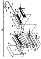
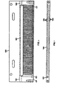
- two carbon pressure plate assemblies 102 are assembled in a carbon collar 103 so that their end surfaces, which contain ink outlet passages, are aligned with corresponding openings in a manifold plate 104 to which the pressure chamber plate assemblies 102 are affixed by screws 105 extending through the manifold plate and into an adjacent pressure chamber plate 106.
- An orifice plate 107 has a linear array of closely spaced orifices 108 which are aligned with the ends of arrays of passages 109 (Fig. 7) in the manifold plate 104 so as to eject ink in response to selective actuation of the pressure plate assemblies.
- a filter layer 110 Interposed between the ends of the pressure plate assemblies 102 and the manifold plate 104 is a filter layer 110 having pores or openings slightly smaller than the orifices 108 in the orifice plate 107 so as to prevent potentially orifice-clogging solid material from reaching the orifices 108 but large enough to permit particles of solid material smaller than the size of the orifices to pass through the filter layer.
- This type of filter is described, for example, in the copending Moynihan et al. application for "Filter Arrangement For Ink Jet Head" Serial No. 08/231,102, filed April 22, 1994 (now US Patent 5724082).
- An ink reservoir 111 mounted against one side of the collar 103 has an ink supply opening 112 which supplies ink to the collar 103. As best seen in Fig. 5, a corresponding opening 113 in the collar is aligned with the opening 112 to receive ink from the reservoir 111.
- a cartridge heater 114 is mounted in a groove 115 formed in the side of the reservoir and in a corresponding groove 116 (Fig. 5) in the side of the collar 103 and is controlled so as to maintain the ink within the assembled ink jet head at a desired temperature during operation of the system.
- Each pressure chamber assembly 102 includes a pressure plate 106 having arrays 117 of closely spaced pressure chambers formed on opposite sides of the plate 106 and each of those arrays is covered by a piezoelectric plate 118 of the type described with respect to Fig. 4 of our WO 95/25637, having an array of electrodes 119 arranged with respect to the array of pressure chambers 117 to change the volume of the corresponding pressure chamber in response to appropriate electrical signals.
- the piezoelectric plate 118 When selectively activated the piezoelectric plate 118 is mechanically distorted in shear mode in the direction toward the adjacent pressure chamber 20 to cause ejection of an ink drop from the orifices with which that pressure chamber communicates.
- Shear-mode operation of a piezoelectric plate is described, for example, in Fischbeck et al US Patent No 4,584,590. Such shear-mode operation does not require any electrode on the opposite site of the piezoelecxyric plate but, of desired, the carbon plate, being conductive, can be used to prove an electrode on the opposite side of the plate.
- the pressure chamber plate 106 which is illustrated in greater detail in Figs. 2 and 7, has a longitudinally extending opening 120 which, in the illustrated embodiment receives ink through an internal passage 123 terminating at an end surface 124 which faces the manifold plate 104 as seen in Fig. 1. As shown in Fig. 1, the surface of the manifold plate 104 facing the pressure chamber plate, has an opening 125 which receives ink from the collar passage 113 and supplies it to a groove 126 (Fig.
- a deareator 128 consisting of a tubular member 129 made of air-permeable, ink-impermeable material, such as extruded polytetrafluoroethylene having a 0.1mm wall thickness and a 1.5mm internal diameter, extends through an opening 130 in the edge of each pressure chamber plate 106 and into the longitudinal opening 120.
- a plug 131 closes the inner end of the tube and the end projecting out of the opening 130 in the plate 106 is connected to a vacuum source 132 supplying sufficient negative pressure, such as 0.7 atmosphere, to reduce the dissolved air content of the ink being supplied to the pressure chambers below the level at which air bubbles can form in the pressure chamber during operation of the ink jet system.
- a porous support such as a rod of porous carbon or a helical wire having a diameter substantially equal to the internal diameter of the tube, is inserted into the tube.
- the end surface 124 of the carbon plate 106 has two arrays of ink passages 133 which extend perpendicularly to the end surface 123 and each of those passages communicates internally with the adjacent end of a corresponding pressure chamber in the arrays 117. Consequently, upon actuation of one of the pressure chambers, ink is forced out of the plate 106 through a corresponding one of the passages 133.
- ink from each of the passages 133 is supplied through a corresponding passage 134 in an adjacent surface of the manifold plate 104 shown in Fig. 4 and, as shown in Fig. 7, the arrays of passages 109 in the opposite surface of the manifold plate extend horizontally along the surface of that plate to convey the ink supplied through the passages 134 in a lateral direction toward the center of the manifold plate.
- Those passages terminate in a central line 135 extending longitudinally along the manifold plate so as to be in line with the line of ink jet orifices 108 in the orifice plate 107.
- carbon is the preferred material for the manifold plate 104, especially for ink jet heads used with hot melt ink
- other materials which can be formed with a sufficiently flat surface and which have a thermal expansion coefficient compatible with adjacent components may also be used.
- steel and ceramics such as alumina and glass, in which appropriate passages can be formed by photoetching, may also be used to form the manifold plate.
- each pressure chamber plate 106 is approximately 75mm long, 22mm wide and 2.5mm thick and each pressure chamber array 117 contains 64 pressure chamber approximately 9mm long, 1mm wide and 0.15mm deep and the manifold plate 104 is approximately 1.4mm thick.
- the total length of the descender which is the ink path leading from the end of the pressure chamber to the orifice in the orifice plate, should be as short as possible, i.e. no more than about 1mm.
- each descender should have a constant cross-section similar to that of the pumping chamber so that its acoustic properties do not result in undesirable reflections, and that it should be short enough that viscous flow losses are not excessive and that it should also be fluidically stiff so that pressure energy losses from the surrounding structure are not excessive
- the descender need not be so limited in length and can consist of a plurality of passages such as those in the manifold plate and within the pressure chamber plate which total as much as 7mm in length without loss of performance.
- the piezoelectric plate which is quite fragile, can be spaced a significantly greater distance away from the substrate being printed by the head and the body of the ink jet array may be made thick enough to be mechanically robust and to provide good thermal uniformity.
- laterally spaced pressure chambers such as those in the arrays 117 may be connected through laterally spaced passages 133 to supply ink to a single line of orifices 108 by using an arrangement of laterally directed passages 109 such as that incorporated into the manifold plate 104.
Landscapes
- Engineering & Computer Science (AREA)
- Manufacturing & Machinery (AREA)
- Physics & Mathematics (AREA)
- Optics & Photonics (AREA)
- Particle Formation And Scattering Control In Inkjet Printers (AREA)
- Ink Jet (AREA)
Description
- This invention relates to a deaeration member for an ink jet head and to an ink jet head provided with an ink deaerator.
- US Patent 4940995 explains that in many ink jet systems ink is supplied to a chamber or passage connected to an orifice from which the ink is ejected drop by drop as a result of successive cycles of decreased and increased pressure applied to the ink in the passage. If the ink introduced into the passage contains dissolved air or other gas, decompression of the ink during reduced-pressure portions of the pressure cycle may cause the dissolved gas to form small bubbles in the ink within the passage. Repeated decompression of the ink in the chamber causes these bubbles to grow and such bubbles can produce malfunction of the ink jet apparatus. In order to overcome this difficulty the ink in the ink jet system is subjected to a reduced pressure applied through a membrane which is permeable to gas but not to ink and according to a feature of the aforesaid US patent the membrane is made of a fluorine containing sheet material which may be fluorosilicone or a fluorocarbon.
- The invention provides an ink jet head including a carbon pressure chamber plate that has an ink deaeration passage through which ink is supplied to the inlet passages leading to the pressure chambers. An internally supported, thin-walled tubular member made of air-permeable, ink-impermeable material connected at one end to a source of reduced pressure is inserted into the ink deaeration passage to provide a unitary ink deareating and pressure chamber carbon plate. This arrangement accomplishes the necessary deaeration of ink immediately before it is supplied to the pressure chambers with minimal space requirements and without necessitating recirculation of ink to an ink reservoir.
- In one aspect of the invention comprises a deaeration member as set out in claim 1 of the accompanying claims.
- In another aspect the invention provides an ink jet head provided with a deaerator and as set out in claim 5 of the accompanying claims.
- In addition to its other advantages disclosed in WO95/2563 a carbon plate is porous, preferably being about 80-90% dense, and the porosity and a vacuum source communicating with the surface of the plate can extract dissolved air from ink in the ink passages separated from the porous carbon material by an air-permeable, ink-impermeable layer. Moreover, the carbon plate may have orifice passages formed in an edge of the plate rather than in one of the sides of the plate. Since engineering grade carbon is friable, i.e., microscopic grains are readily broken away from a carbon body, it is easily shaped without producing burrs. As described in "Graphite Machinery Made Easy", EDM Today, Sept./Oct. 1993 pp. 24ff, the relative softness and lack of ductility of such carbon allows it to be cut at high feed rates with little distortion and low tool wear. These characteristics permit carbon blocks to be readily formed into components of ink jet heads by conventional or unique machining techniques.
How the invention may be put into effect will now be described, by way of example only, in the accompanying drawings, in which - Fig. 1 is an exploded perspective view illustrating a representative embodiment of a simplified ink jet head and deareation member in accordance with the invention;
- Fig. 2 is a side view illustrating a representative carbon pressure chamber plate of the type used in the arrangement shown in Fig. 1;
- Fig. 3 is an end view of the representative carbon pressure chamber plate shown in Fig. 2;
- Fig. 4 is a top view of the carbon collar block used in the arrangement shown in Fig. 1;
- Fig. 5 is a side view of the collar block shown in Fig. 4;
- Fig. 6 is a plan view showing one side of a representative carbon manifold plate of the type used in the arrangement shown in Fig 1;
- Fig. 7 is a plan view showing the opposite side of the manifold plate of Fig. 6; and
- Fig 8 is a perspective view showing a typical shaping tool for shaping arrays of ink passages in a carbon body for use in an ink jet head.
-
- In an embodiment of the invention shown in Figs 1 - 7, an ink jet head is assembled from a plurality of carbon components.
- A carbon plate forming one of the components may be machined by micromachining techniques from opposite sides to produce chambers and passages required for the ink jet head. The plate may be made of engineering carbon graphite, which is preferably about 80-90% dense, providing a slightly porous plate structure. The carbon plate can be machined by milling, drilling, broaching, grinding and the like, using conventional tools providing high material removal rates with minimum tool wear, to produce openings with much closer tolerances than the conventional metal plates of the type described, for example, in the Hoisington et al. Patent No. 4,835,554. Because the carbon material is friable, no burrs are produced during machining. Moreover, the coefficient of thermal expansion of the carbon graphite body is substantially the same as that of the ceramic piezoelectric material of which the piezoelectric plate 23 is made so as to reduce or substantially eliminate thermal stresses which occur between those components of the head as a result of variations in temperature.
- The preferred carbon material for use in forming components on ink jet heads is polycrystalline graphite, which is a mixture of small crystals of graphite sintered with amorphous carbon (lamp black). This produces an amorphous matrix of small (0.025-5µ) grains and smaller (0.005-0.2µ) pores. This material, which is different from powdered graphite and carbon fiber materials, offers many benefits, including good thermal conductivity, coefficient of thermal expansion close to ceramic piezoelectric materials, good machinability, dimensional stability and chemical inertness.
- The thermal properties of polycrystalline graphite (Grade DFP-1 available from POCO Graphite, Inc., Decatur, Texas) and other materials which might be considered for printheads are compared with those of lead zinc titanate (PZT) ceramic piezoelectric material in Table 1 below:
Material Conductivity (W/CmK) Thermal Expansion (µ/m/degC) Modulus (x105kg/cm_) PZT 0.015 2 to 4 7 Thermoplastic (Ultem) 0.0022 56 0.15 Aluminum (6000) 1.7 23.4 7 Carbon (DFP-1) 0.75 8.4 1.1 - The Ultem (as well as other thermoplastics) has both poor conductivity and a very high thermal expansion coefficient. The conductivity of aluminum is attractive, but its high thermal expansion and modulus are problems. Polycrystalline carbon offers a good combination of all three properties.
- A potentially prohibitive aspect of the use of carbon members for ink jet components is the forming of closely spaced arrays of pressure chambers and other multitudinous, long aspect ratio, channels with precise dimensions. Using an end mill for these features could be expected to result in excessively long machine cycle times. To overcome this problem, a desired array of adjacent channel profiles is shaped in the surface of a carbon body by a specially formed
tool 95, shown in Fig. 8, in a series of repeated linear motions or "scrapes." In thetool 95 for example, an array of 64 short uniformly spacedteeth 96 may be provided at one end of the tool to cut 64 parallel pressure chambers in the surface of a carbon plate. If the tool cuts at 0.025mm per scrape, a depth of 0.15mm can be achieved in 6 scrapes, which requires only a few seconds of machine time. Thetool 95 makes an array of channels equal to the width of the tool, and can make a wider array by taking repeat adjacent passes. Tool irregularities are averaged out by taking finish cuts in the reverse direction or at a one-tooth offset. Reversing the tool also allows the formation of steeper channel ends when this is required. This technique can be used to make pumping chambers, manifold passages, flow-through passages, and the like. Finally, channels of variable or tapered depth can be made as well, by raising or lowering the tool as a cut is being made. - For an array of closely spaced deep, small diameter holes in a carbon body, where the depth is more than 3 times the drill diameter, drilling can become difficult and expensive. To provide an array of closely spaced holes having a diameter of, for example, 0.28mm through a carbon plate 1.75mm thick would require a great deal of time and a number of expensive drills. To form such an array in a simple manner, matching arrays of channels (which may be semi-hexagonal in shape) 0.14mm deep are formed in two matching blocks of carbon which are then bonded together with adhesive to form a single block containing an array of parallel, long 0.28mm diameter holes. This block is then sliced perpendicularly to the axes of the holes and ground flat to form the array bodies. The adhesive joint down the middle of the array body has been found to be very strong.
- Polycrystalline carbon is easily bonded by a variety of adhesives. Three systems are particularly compatible with carbon in hot melt ink jet head applications. The first is a simple dispensed epoxy which works well for coarse scale joints. The second is a thermoplastic sheet adhesive. Using this technique, a thin teflon (TFE) sheet compressed at elevated temperature and pressure provides a tenacious bond between flat surfaces of polycrystalline carbon. Similarly, acrylic sheet adhesives should perform well at lower temperature. In the third technique, a dilute sprayed B-stage epoxy system is applied to the surfaces to be bonded. This has been shown to be adaptable to the complex geometries of ink jet printheads, yet high in strength at elevated temperatures.
- There is some challenge in bonding a porous material like carbon with a spray application technique. Since excess adhesive will clog small passages, and thin layers may be drawn by capillary forces into the carbon body pores, careful control of process variables is required. In particular, the carbon pore structure must be uniform, the spray-deposited layer thickness must be small compared to the particle/pore size, and the heat cure process must be tuned to the adhesive rheology.
- In addition, a carbon plate is especially advantageous for ink jet heads used with hot melt ink. Because of its high thermal conductivity, the carbon plate provides excellent heat conduction from heaters mounted at relatively remote locations in the head to all of the ink passages in the head. This assures that the hot melt ink at each of the orifices is at the same temperature and therefore has the same viscosity, thereby providing good uniformity of operation throughout the length of the array of orifices.
- In certain high-frequency ink jet applications, the rigidity of the walls of the pressure chambers formed in the carbon plate may be less than desired, requiring a higher operating voltage for the piezoelectric actuating plate. To alleviate this, the surfaces of the pressure chambers formed in the carbon plate may be coated with a thin layer, such as 0.01 to 0.1mm thick, of a very hard (i.e. high modulus of rigidity) material such as a carbide or nitride, e.g., silicon carbide or nitride, boron carbide or nitride, tungsten carbide or nitride, tantalum carbide or nitride, or the like. Preferably, the coating is applied by chemical vapor deposition.
- In this embodiment, as illustrated in the exploded view of Fig. 1, two carbon
pressure plate assemblies 102, described in greater detail hereinafter, are assembled in acarbon collar 103 so that their end surfaces, which contain ink outlet passages, are aligned with corresponding openings in amanifold plate 104 to which the pressurechamber plate assemblies 102 are affixed byscrews 105 extending through the manifold plate and into an adjacentpressure chamber plate 106. Anorifice plate 107 has a linear array of closely spacedorifices 108 which are aligned with the ends of arrays of passages 109 (Fig. 7) in themanifold plate 104 so as to eject ink in response to selective actuation of the pressure plate assemblies. - Interposed between the ends of the
pressure plate assemblies 102 and themanifold plate 104 is afilter layer 110 having pores or openings slightly smaller than theorifices 108 in theorifice plate 107 so as to prevent potentially orifice-clogging solid material from reaching theorifices 108 but large enough to permit particles of solid material smaller than the size of the orifices to pass through the filter layer. This type of filter is described, for example, in the copending Moynihan et al. application for "Filter Arrangement For Ink Jet Head" Serial No. 08/231,102, filed April 22, 1994 (now US Patent 5724082). - An
ink reservoir 111, mounted against one side of thecollar 103 has anink supply opening 112 which supplies ink to thecollar 103. As best seen in Fig. 5, acorresponding opening 113 in the collar is aligned with theopening 112 to receive ink from thereservoir 111. In addition, if hot melt ink is to be used in the ink jet head, acartridge heater 114 is mounted in agroove 115 formed in the side of the reservoir and in a corresponding groove 116 (Fig. 5) in the side of thecollar 103 and is controlled so as to maintain the ink within the assembled ink jet head at a desired temperature during operation of the system. - Each
pressure chamber assembly 102 includes apressure plate 106 havingarrays 117 of closely spaced pressure chambers formed on opposite sides of theplate 106 and each of those arrays is covered by apiezoelectric plate 118 of the type described with respect to Fig. 4 of our WO 95/25637, having an array ofelectrodes 119 arranged with respect to the array ofpressure chambers 117 to change the volume of the corresponding pressure chamber in response to appropriate electrical signals. When selectively activated thepiezoelectric plate 118 is mechanically distorted in shear mode in the direction toward the adjacent pressure chamber 20 to cause ejection of an ink drop from the orifices with which that pressure chamber communicates. Shear-mode operation of a piezoelectric plate is described, for example, in Fischbeck et al US Patent No 4,584,590. Such shear-mode operation does not require any electrode on the opposite site of the piezoelecxyric plate but, of desired, the carbon plate, being conductive, can be used to prove an electrode on the opposite side of the plate. - The
pressure chamber plate 106, which is illustrated in greater detail in Figs. 2 and 7, has alongitudinally extending opening 120 which, in the illustrated embodiment receives ink through aninternal passage 123 terminating at anend surface 124 which faces themanifold plate 104 as seen in Fig. 1. As shown in Fig. 1, the surface of themanifold plate 104 facing the pressure chamber plate, has anopening 125 which receives ink from thecollar passage 113 and supplies it to a groove 126 (Fig. 7) on the opposite side of the manifold plate, from which ink passes through twofurther openings 127 in the manifold plate to thepassages 123 in thepressure plates 106 so that the ink is distributed through thelongitudinal opening 120 to all of the pressure chambers in both of thearrays 117 in each plate. - In order to extract dissolved air from the ink as it is being supplied to the
arrays 117 of pressure chambers, adeareator 128 consisting of atubular member 129 made of air-permeable, ink-impermeable material, such as extruded polytetrafluoroethylene having a 0.1mm wall thickness and a 1.5mm internal diameter, extends through anopening 130 in the edge of eachpressure chamber plate 106 and into thelongitudinal opening 120. Aplug 131 closes the inner end of the tube and the end projecting out of theopening 130 in theplate 106 is connected to avacuum source 132 supplying sufficient negative pressure, such as 0.7 atmosphere, to reduce the dissolved air content of the ink being supplied to the pressure chambers below the level at which air bubbles can form in the pressure chamber during operation of the ink jet system. In order to prevent thetube 129 from collapsing in response to application of negative pressure, a porous support, such as a rod of porous carbon or a helical wire having a diameter substantially equal to the internal diameter of the tube, is inserted into the tube. - As shown in Fig. 3, the
end surface 124 of thecarbon plate 106 has two arrays ofink passages 133 which extend perpendicularly to theend surface 123 and each of those passages communicates internally with the adjacent end of a corresponding pressure chamber in thearrays 117. Consequently, upon actuation of one of the pressure chambers, ink is forced out of theplate 106 through a corresponding one of thepassages 133. - After passing through the
filter layer 110, ink from each of thepassages 133 is supplied through acorresponding passage 134 in an adjacent surface of themanifold plate 104 shown in Fig. 4 and, as shown in Fig. 7, the arrays ofpassages 109 in the opposite surface of the manifold plate extend horizontally along the surface of that plate to convey the ink supplied through thepassages 134 in a lateral direction toward the center of the manifold plate. Those passages terminate in acentral line 135 extending longitudinally along the manifold plate so as to be in line with the line ofink jet orifices 108 in theorifice plate 107. - Although carbon is the preferred material for the
manifold plate 104, especially for ink jet heads used with hot melt ink, other materials which can be formed with a sufficiently flat surface and which have a thermal expansion coefficient compatible with adjacent components may also be used. For example, steel and ceramics such as alumina and glass, in which appropriate passages can be formed by photoetching, may also be used to form the manifold plate. - In a typical embodiment of the type shown in Figs. 1-7, each
pressure chamber plate 106 is approximately 75mm long, 22mm wide and 2.5mm thick and eachpressure chamber array 117 contains 64 pressure chamber approximately 9mm long, 1mm wide and 0.15mm deep and themanifold plate 104 is approximately 1.4mm thick. - Heretofore it was believed that the total length of the descender, which is the ink path leading from the end of the pressure chamber to the orifice in the orifice plate, should be as short as possible, i.e. no more than about 1mm. Although it is clear that each descender should have a constant cross-section similar to that of the pumping chamber so that its acoustic properties do not result in undesirable reflections, and that it should be short enough that viscous flow losses are not excessive and that it should also be fluidically stiff so that pressure energy losses from the surrounding structure are not excessive, it has now been determined that, in ink jet heads made of carbon components, the descender need not be so limited in length and can consist of a plurality of passages such as those in the manifold plate and within the pressure chamber plate which total as much as 7mm in length without loss of performance. This permits greater flexibility in the design of ink jet heads in several respects. For example, the piezoelectric plate, which is quite fragile, can be spaced a significantly greater distance away from the substrate being printed by the head and the body of the ink jet array may be made thick enough to be mechanically robust and to provide good thermal uniformity. Moreover, laterally spaced pressure chambers such as those in the
arrays 117 may be connected through laterally spacedpassages 133 to supply ink to a single line oforifices 108 by using an arrangement of laterally directedpassages 109 such as that incorporated into themanifold plate 104.
Claims (9)
- A deaeration member (128) for an ink jet head made of air-permeable, ink-impermeable material characterized in that the member is tubular and is adapted to be inserted into an ink passage (12) in an ink jet head, one end (131) of the tubular member being sealed and the other end of the tubular member being connectable to a source (132) of subatmospheric pressure.
- The deaeration member of claim 1, wherein the tubular member (129) is made of polytetrafluoroethylene
- The deaeration member of claim 1 or 2, including a porous support member disposed within the tubular member.
- The deaeration member of any of claims 1 -3, wherein the tubular member (120) has a 0.1mm wall thickness and a 1.5mm diameter.
- An ink jet head provided with an ink deaerator of an air-permeable ink-impermeable material, characterized in that the ink jet head includes a carbon pressure chamber plate (106) having an ink deaeration passage (120) for supply of ink therethrough to inlet passages leading to pressure chambers (117) and in that the deaerator comprises an internally supported, thin-walled tubular member (129) of air-permeable, ink-impermeable material located within the ink deaeration passage for connection at one end to a source (132) of reduced pressure.
- The head of claim 5, wherein the plate (105) is of polycrystalline graphite.
- The head of claim 5 or 6 where the plate is about 80%-90% dense.
- The head of claim 5, 6 or 7 wherein the tubular member (129) is of polytetrafluoroethylene.
- An ink jet head according to any of claims 5 - 8, filled with hot melt ink.
Applications Claiming Priority (3)
| Application Number | Priority Date | Filing Date | Title |
|---|---|---|---|
| US215301 | 1994-03-21 | ||
| US08/215,301 US5659346A (en) | 1994-03-21 | 1994-03-21 | Simplified ink jet head |
| EP95914098A EP0699137B1 (en) | 1994-03-21 | 1995-03-17 | Simplified ink jet head |
Related Parent Applications (1)
| Application Number | Title | Priority Date | Filing Date |
|---|---|---|---|
| EP95914098A Division EP0699137B1 (en) | 1994-03-21 | 1995-03-17 | Simplified ink jet head |
Publications (3)
| Publication Number | Publication Date |
|---|---|
| EP0896879A2 EP0896879A2 (en) | 1999-02-17 |
| EP0896879A3 EP0896879A3 (en) | 1999-06-23 |
| EP0896879B1 true EP0896879B1 (en) | 2002-10-09 |
Family
ID=22802438
Family Applications (3)
| Application Number | Title | Priority Date | Filing Date |
|---|---|---|---|
| EP98203787A Expired - Lifetime EP0896880B1 (en) | 1994-03-21 | 1995-03-17 | Simplified ink jet head |
| EP95914098A Expired - Lifetime EP0699137B1 (en) | 1994-03-21 | 1995-03-17 | Simplified ink jet head |
| EP98203766A Expired - Lifetime EP0896879B1 (en) | 1994-03-21 | 1995-03-17 | Simplified ink jet head |
Family Applications Before (2)
| Application Number | Title | Priority Date | Filing Date |
|---|---|---|---|
| EP98203787A Expired - Lifetime EP0896880B1 (en) | 1994-03-21 | 1995-03-17 | Simplified ink jet head |
| EP95914098A Expired - Lifetime EP0699137B1 (en) | 1994-03-21 | 1995-03-17 | Simplified ink jet head |
Country Status (7)
| Country | Link |
|---|---|
| US (5) | US5659346A (en) |
| EP (3) | EP0896880B1 (en) |
| JP (4) | JP2868622B2 (en) |
| KR (1) | KR100194533B1 (en) |
| CA (1) | CA2163369C (en) |
| DE (3) | DE69509986T2 (en) |
| WO (1) | WO1995025637A1 (en) |
Families Citing this family (138)
| Publication number | Priority date | Publication date | Assignee | Title |
|---|---|---|---|---|
| US5659346A (en) | 1994-03-21 | 1997-08-19 | Spectra, Inc. | Simplified ink jet head |
| US5474032A (en) * | 1995-03-20 | 1995-12-12 | Krietzman; Mark H. | Suspended feline toy and exerciser |
| US5771052A (en) * | 1994-03-21 | 1998-06-23 | Spectra, Inc. | Single pass ink jet printer with offset ink jet modules |
| JPH08267758A (en) * | 1995-03-28 | 1996-10-15 | Sony Corp | Orifice plate, manufacture of the same, liquid mixing device and printer |
| US5847734A (en) | 1995-12-04 | 1998-12-08 | Pawlowski, Jr.; Norman E. | Air purge system for an ink-jet printer |
| US5757400A (en) * | 1996-02-01 | 1998-05-26 | Spectra, Inc. | High resolution matrix ink jet arrangement |
| US5755909A (en) * | 1996-06-26 | 1998-05-26 | Spectra, Inc. | Electroding of ceramic piezoelectric transducers |
| US5858194A (en) * | 1996-07-18 | 1999-01-12 | Beckman Instruments, Inc. | Capillary, interface and holder |
| JP3473675B2 (en) * | 1997-01-24 | 2003-12-08 | セイコーエプソン株式会社 | Ink jet recording head |
| JPH10202882A (en) * | 1997-01-28 | 1998-08-04 | Seiko Instr Inc | Recording head |
| JPH10202853A (en) * | 1997-01-29 | 1998-08-04 | Konica Corp | Ink jet printer |
| JPH10264374A (en) * | 1997-03-27 | 1998-10-06 | Seiko Epson Corp | Ink jet recording head |
| KR100209513B1 (en) | 1997-04-22 | 1999-07-15 | 윤종용 | Active liquid containing and supplying apparatus in inkjet print head |
| US6053976A (en) * | 1997-05-08 | 2000-04-25 | Fuji Photo Film Co., Ltd. | Fluid injecting apparatus and method of manufacturing fluid injection apparatus |
| JP3809706B2 (en) * | 1997-06-16 | 2006-08-16 | ブラザー工業株式会社 | Ink jet printer head and method for processing and inspecting ink jet printer head |
| US7195339B2 (en) * | 1997-07-15 | 2007-03-27 | Silverbrook Research Pty Ltd | Ink jet nozzle assembly with a thermal bend actuator |
| US20110228008A1 (en) * | 1997-07-15 | 2011-09-22 | Silverbrook Research Pty Ltd | Printhead having relatively sized fluid ducts and nozzles |
| US6648453B2 (en) * | 1997-07-15 | 2003-11-18 | Silverbrook Research Pty Ltd | Ink jet printhead chip with predetermined micro-electromechanical systems height |
| US7337532B2 (en) * | 1997-07-15 | 2008-03-04 | Silverbrook Research Pty Ltd | Method of manufacturing micro-electromechanical device having motion-transmitting structure |
| US6935724B2 (en) | 1997-07-15 | 2005-08-30 | Silverbrook Research Pty Ltd | Ink jet nozzle having actuator with anchor positioned between nozzle chamber and actuator connection point |
| AUPP654398A0 (en) * | 1998-10-16 | 1998-11-05 | Silverbrook Research Pty Ltd | Micromechanical device and method (ij46g) |
| US7465030B2 (en) * | 1997-07-15 | 2008-12-16 | Silverbrook Research Pty Ltd | Nozzle arrangement with a magnetic field generator |
| US6986613B2 (en) * | 1997-07-15 | 2006-01-17 | Silverbrook Research Pty Ltd | Keyboard |
| US6682174B2 (en) | 1998-03-25 | 2004-01-27 | Silverbrook Research Pty Ltd | Ink jet nozzle arrangement configuration |
| US20040130599A1 (en) * | 1997-07-15 | 2004-07-08 | Silverbrook Research Pty Ltd | Ink jet printhead with amorphous ceramic chamber |
| US6712453B2 (en) * | 1997-07-15 | 2004-03-30 | Silverbrook Research Pty Ltd. | Ink jet nozzle rim |
| US7468139B2 (en) * | 1997-07-15 | 2008-12-23 | Silverbrook Research Pty Ltd | Method of depositing heater material over a photoresist scaffold |
| US7556356B1 (en) * | 1997-07-15 | 2009-07-07 | Silverbrook Research Pty Ltd | Inkjet printhead integrated circuit with ink spread prevention |
| US6188415B1 (en) * | 1997-07-15 | 2001-02-13 | Silverbrook Research Pty Ltd | Ink jet printer having a thermal actuator comprising an external coil spring |
| EP0903238A3 (en) * | 1997-08-18 | 2000-11-08 | Hewlett-Packard Company | Ink delivery system for ink-jet printer |
| US6231177B1 (en) * | 1997-09-29 | 2001-05-15 | Sarnoff Corporation | Final print medium having target regions corresponding to the nozzle of print array |
| US6572221B1 (en) | 1997-10-10 | 2003-06-03 | Xaar Technology Limited | Droplet deposition apparatus for ink jet printhead |
| GB9721555D0 (en) * | 1997-10-10 | 1997-12-10 | Xaar Technology Ltd | Droplet deposition apparatus and methods of manufacture thereof |
| US6116726A (en) * | 1998-05-28 | 2000-09-12 | Hewlett-Packard Company | Ink jet printer cartridge with inertially-driven air evacuation apparatus and method |
| US6902255B1 (en) * | 1998-10-16 | 2005-06-07 | Silverbrook Research Pty Ltd | Inkjet printers |
| RU2144471C1 (en) | 1998-11-03 | 2000-01-20 | Самсунг Электроникс Ко., Лтд. | Method and device for assembling of microinjector |
| JP3166741B2 (en) | 1998-12-07 | 2001-05-14 | 日本電気株式会社 | Ink jet recording head and method of manufacturing the same |
| JP3395679B2 (en) * | 1998-12-16 | 2003-04-14 | 株式会社村田製作所 | Polarization treatment method for piezoelectric body |
| JP2000211138A (en) * | 1999-01-22 | 2000-08-02 | Oce Technol Bv | Ink-jet printing head and production thereof |
| US6533376B1 (en) | 1999-01-29 | 2003-03-18 | Spectra, Inc. | Conditioning ink jet orifices |
| JP2000280481A (en) * | 1999-04-01 | 2000-10-10 | Matsushita Electric Ind Co Ltd | Ink jet head and its manufacture |
| US6357867B1 (en) | 1999-05-07 | 2002-03-19 | Spectra, Inc. | Single-pass inkjet printing |
| GB9916532D0 (en) | 1999-07-14 | 1999-09-15 | Videojet Systems Int | A droplet generator for a continuous stream ink jet print head |
| US6755511B1 (en) * | 1999-10-05 | 2004-06-29 | Spectra, Inc. | Piezoelectric ink jet module with seal |
| US6427597B1 (en) | 2000-01-27 | 2002-08-06 | Patrice M. Aurenty | Method of controlling image resolution on a substrate |
| US6626514B2 (en) * | 2000-03-31 | 2003-09-30 | Canon Kabushiki Kaisha | Liquid discharge recording head, method of manufacture therefor, and liquid discharge recording apparatus |
| JP2001353871A (en) | 2000-04-12 | 2001-12-25 | Seiko Epson Corp | Ink jet recording head |
| JP2002103597A (en) * | 2000-07-25 | 2002-04-09 | Sony Corp | Printer and printer head |
| US6848773B1 (en) * | 2000-09-15 | 2005-02-01 | Spectra, Inc. | Piezoelectric ink jet printing module |
| US6540339B2 (en) * | 2001-03-21 | 2003-04-01 | Hewlett-Packard Company | Flextensional transducer assembly including array of flextensional transducers |
| US6558450B2 (en) * | 2001-03-22 | 2003-05-06 | Celgard Inc. | Method for debubbling an ink |
| GB0121625D0 (en) * | 2001-09-07 | 2001-10-31 | Xaar Technology Ltd | Droplet deposition apparatus |
| DE10239002B4 (en) * | 2001-09-11 | 2007-04-12 | Heidelberger Druckmaschinen Ag | Inkjet printhead with drying device |
| US6620237B2 (en) | 2001-11-15 | 2003-09-16 | Spectra, Inc. | Oriented piezoelectric film |
| US7204586B2 (en) | 2001-12-18 | 2007-04-17 | Dimatix, Inc. | Ink jet printing module |
| JP3606324B2 (en) * | 2001-12-20 | 2005-01-05 | セイコーエプソン株式会社 | Method for manufacturing nozzle plate for liquid droplet ejection head |
| US7045934B2 (en) * | 2002-04-11 | 2006-05-16 | Ernest Geskin | Method for jet formation and the apparatus for the same |
| JP2003311973A (en) * | 2002-04-19 | 2003-11-06 | Sony Corp | Liquid discharge device, printer, and manufacturing method for liquid discharge device |
| US7052117B2 (en) | 2002-07-03 | 2006-05-30 | Dimatix, Inc. | Printhead having a thin pre-fired piezoelectric layer |
| JP3997865B2 (en) * | 2002-08-29 | 2007-10-24 | ブラザー工業株式会社 | Inkjet printer head |
| US7044591B2 (en) * | 2002-09-25 | 2006-05-16 | Brother Kogya Kabushiki Kaisha | Ink-jet head, filter assembly used for manufacturing the ink-jet head, and method for manufacturing the ink-jet head using the filter assembly |
| US6880926B2 (en) * | 2002-10-31 | 2005-04-19 | Hewlett-Packard Development Company, L.P. | Circulation through compound slots |
| US20040252161A1 (en) * | 2003-06-11 | 2004-12-16 | Andreas Bibl | Tilt head cleaner |
| US7431956B2 (en) | 2003-06-20 | 2008-10-07 | Sensient Imaging Technologies, Inc. | Food grade colored fluids for printing on edible substrates |
| CA2532281A1 (en) * | 2003-08-18 | 2005-02-24 | Oce Technologies B.V. | A meltable ink suitable for use in an inkjet printer provided with a carbon duct plate |
| US7207641B2 (en) * | 2003-09-05 | 2007-04-24 | Konica Minolta Holdings, Inc. | Inkjet head |
| US7309943B2 (en) * | 2003-09-08 | 2007-12-18 | New Scale Technologies, Inc. | Mechanism comprised of ultrasonic lead screw motor |
| US6940209B2 (en) | 2003-09-08 | 2005-09-06 | New Scale Technologies | Ultrasonic lead screw motor |
| US7170214B2 (en) * | 2003-09-08 | 2007-01-30 | New Scale Technologies, Inc. | Mechanism comprised of ultrasonic lead screw motor |
| KR101220272B1 (en) | 2003-12-30 | 2013-01-09 | 후지필름 디마틱스, 인크. | Drop ejection assembly |
| ATE537971T1 (en) * | 2003-12-30 | 2012-01-15 | Dimatix Inc | DROP EJECTION ARRANGEMENT |
| US20080075859A1 (en) * | 2004-01-20 | 2008-03-27 | Baker Richard J | Printing, Depositing, or Coating On Flowable Substrates |
| US8753702B2 (en) | 2004-01-20 | 2014-06-17 | Fujifilm Dimatix, Inc. | Printing on edible substrates |
| US7052122B2 (en) * | 2004-02-19 | 2006-05-30 | Dimatix, Inc. | Printhead |
| JP4581426B2 (en) * | 2004-02-27 | 2010-11-17 | ブラザー工業株式会社 | Inkjet head |
| KR100537522B1 (en) * | 2004-02-27 | 2005-12-19 | 삼성전자주식회사 | Piezoelectric type inkjet printhead and manufacturing method of nozzle plate |
| US8491076B2 (en) | 2004-03-15 | 2013-07-23 | Fujifilm Dimatix, Inc. | Fluid droplet ejection devices and methods |
| US7281778B2 (en) | 2004-03-15 | 2007-10-16 | Fujifilm Dimatix, Inc. | High frequency droplet ejection device and method |
| US7431957B2 (en) | 2004-06-10 | 2008-10-07 | Sensient Imaging Technologies, Inc. | Food grade ink jet inks for printing on edible substrates |
| US7347532B2 (en) * | 2004-08-05 | 2008-03-25 | Fujifilm Dimatix, Inc. | Print head nozzle formation |
| US7344230B2 (en) | 2004-09-07 | 2008-03-18 | Fujifilm Dimatix, Inc. | Fluid drop ejection system capable of removing dissolved gas from fluid |
| US7637592B2 (en) | 2006-05-26 | 2009-12-29 | Fujifilm Dimatix, Inc. | System and methods for fluid drop ejection |
| US7484836B2 (en) * | 2004-09-20 | 2009-02-03 | Fujifilm Dimatix, Inc. | System and methods for fluid drop ejection |
| BRPI0515855B1 (en) * | 2004-10-22 | 2017-03-07 | Hewlett Packard Development Co Lp | liquid / gas separator |
| US7238224B2 (en) * | 2004-10-29 | 2007-07-03 | Hewlett-Packard Development Company, L.P. | Fluid-gas separator |
| US6938905B1 (en) | 2004-11-05 | 2005-09-06 | Haiming Tsai | Hand truck |
| US7325907B2 (en) * | 2004-11-17 | 2008-02-05 | Fujifilm Dimatix, Inc. | Printhead |
| JP4927400B2 (en) * | 2004-12-24 | 2012-05-09 | 富士フイルム株式会社 | Inorganic piezoelectric body poling treatment method and piezoelectric element manufacturing method |
| WO2006074016A2 (en) | 2004-12-30 | 2006-07-13 | Fujifilm Dimatix, Inc. | Ink jet printing |
| US20060152558A1 (en) * | 2005-01-07 | 2006-07-13 | Hoisington Paul A | Fluid drop ejection |
| US7465335B2 (en) * | 2005-02-02 | 2008-12-16 | United Technologies Corporation | Fuel deoxygenation system with textured oxygen permeable membrane |
| KR100657950B1 (en) * | 2005-02-05 | 2006-12-14 | 삼성전자주식회사 | Ink supply apparatus and ink-jet printhead package having the same |
| JP4929598B2 (en) * | 2005-02-07 | 2012-05-09 | 富士ゼロックス株式会社 | Droplet discharge head and droplet discharge apparatus |
| US7681994B2 (en) * | 2005-03-21 | 2010-03-23 | Fujifilm Dimatix, Inc. | Drop ejection device |
| US7621625B2 (en) | 2005-03-31 | 2009-11-24 | Heidelberger Druckmaschinen Ag | Ink jet device with individual shut-off |
| US7360882B2 (en) * | 2005-04-22 | 2008-04-22 | Toshiba Tec Kabushiki Kaisha | Ink-jet recording apparatus, method of removing air of ink-jet recording apparatus and removing air device |
| WO2006121936A2 (en) | 2005-05-09 | 2006-11-16 | Fujifilm Dimatix, Inc. | Ink jet printing system |
| EA012656B1 (en) * | 2005-05-25 | 2009-12-30 | Аэроджен, Инк. | Vibration systems and use thereof |
| US7600863B2 (en) * | 2006-01-04 | 2009-10-13 | Xerox Corporation | Inkjet jet stack external manifold |
| KR101263384B1 (en) * | 2006-01-16 | 2013-05-21 | 삼성디스플레이 주식회사 | Alignment layer printing apparatus having ink jet head and method for printing alignment lay using the same |
| US7988247B2 (en) | 2007-01-11 | 2011-08-02 | Fujifilm Dimatix, Inc. | Ejection of drops having variable drop size from an ink jet printer |
| JP5242238B2 (en) * | 2007-05-30 | 2013-07-24 | オセ−テクノロジーズ・ベー・ヴエー | Manufacturing method of piezoelectric ink jet device |
| JP2010076413A (en) * | 2007-12-11 | 2010-04-08 | Seiko Epson Corp | Liquid supply device and liquid jetting apparatus |
| US10531681B2 (en) | 2008-04-25 | 2020-01-14 | Sensient Colors Llc | Heat-triggered colorants and methods of making and using the same |
| CN103640336B (en) | 2008-05-23 | 2015-12-02 | 富士胶片株式会社 | Fluid droplet ejecting device |
| CN102126347A (en) * | 2008-08-19 | 2011-07-20 | 精工爱普生株式会社 | Liquid ejecting apparatus, defoaming mechanism, and manufacturing method thereof |
| US9113647B2 (en) | 2008-08-29 | 2015-08-25 | Sensient Colors Llc | Flavored and edible colored waxes and methods for precision deposition on edible substrates |
| CN105968954A (en) | 2009-07-20 | 2016-09-28 | 马克姆-伊玛杰公司 | Solvent-based inkjet ink formulations |
| US8395798B2 (en) | 2010-07-15 | 2013-03-12 | Fujifilm Dimatix, Inc. | Printing objects using a rolling buffer |
| US8690302B2 (en) | 2010-12-06 | 2014-04-08 | Palo Alto Research Center Incorporated | Bubble removal for ink jet printing |
| US8371683B2 (en) | 2010-12-23 | 2013-02-12 | Palo Alto Research Center Incorporated | Particle removal device for ink jet printer |
| US9676045B2 (en) | 2011-02-28 | 2017-06-13 | Corning Optical Communications Rf Llc | Electrodes, components, apparatuses, and methods for burr-free or substantially burr-free electrochemical machining |
| US8403447B1 (en) | 2011-09-13 | 2013-03-26 | Fujifilm Dimatix, Inc. | Fluid jetting with delays |
| US8696098B2 (en) * | 2011-12-09 | 2014-04-15 | Xerox Corporation | Printhead having particle circulation with separation |
| CN104245330B (en) * | 2012-03-05 | 2016-06-29 | 富士胶卷迪马蒂克斯股份有限公司 | The recirculation of ink |
| US8721041B2 (en) * | 2012-08-13 | 2014-05-13 | Xerox Corporation | Printhead having a stepped flow path to direct purged ink into a collecting tray |
| JP2014040071A (en) * | 2012-08-23 | 2014-03-06 | Seiko Epson Corp | Liquid ejection head and liquid ejection device |
| US9162230B2 (en) | 2013-03-11 | 2015-10-20 | Weiler And Company, Inc. | Dual tapered orifice plate for a grinding machine |
| WO2015005154A1 (en) * | 2013-07-09 | 2015-01-15 | Canon Kabushiki Kaisha | Liquid ejection head and process for producing the same |
| KR102161692B1 (en) * | 2013-12-06 | 2020-10-07 | 삼성디스플레이 주식회사 | Inket printhead and method of manufacturing the same |
| EP3100860B1 (en) * | 2014-01-31 | 2020-08-05 | Konica Minolta, Inc. | Inkjet head and inkjet printing apparatus |
| US9974541B2 (en) | 2014-02-14 | 2018-05-22 | Covidien Lp | End stop detection |
| GB2527804B (en) * | 2014-07-02 | 2016-07-27 | Xaar Technology Ltd | Droplet deposition apparatus |
| KR102621740B1 (en) * | 2016-12-20 | 2024-01-05 | 주식회사 탑 엔지니어링 | Inkjet type liquid dispensing module and deaeration method thereof |
| WO2018185515A1 (en) | 2017-04-07 | 2018-10-11 | Dover Europe Sàrl | Method and device to manage different screens with different sizes on a printer |
| CN110709812A (en) | 2017-04-07 | 2020-01-17 | 多佛欧洲有限责任公司 | Method and apparatus for managing different screens having different sizes of a printer |
| US11513744B2 (en) | 2017-04-07 | 2022-11-29 | Dover Europe Sàrl | Method and device to manage different screens on a production line |
| KR102157206B1 (en) * | 2018-12-20 | 2020-09-17 | 동의대학교 산학협력단 | Pneumatic dispenser without adhesion process and pneumatic printing system comprising the same |
| JP2020104366A (en) * | 2018-12-27 | 2020-07-09 | セイコーエプソン株式会社 | Liquid discharge head, and liquid discharge device |
| JP7384561B2 (en) * | 2019-02-18 | 2023-11-21 | ローム株式会社 | Nozzle substrate, inkjet print head and nozzle substrate manufacturing method |
| US11766829B2 (en) | 2019-09-11 | 2023-09-26 | Xerox Corporation | Surface treated additive manufacturing printhead nozzles and methods for the same |
| CN111439034A (en) | 2020-05-13 | 2020-07-24 | 苏州新锐发科技有限公司 | Piezoelectric ink-jet printing device with through hole on piezoelectric plate |
| CN111660671A (en) | 2020-05-13 | 2020-09-15 | 苏州新锐发科技有限公司 | Piezoelectric ink jet printhead and printing system using multiple inks |
| CN111532027A (en) | 2020-05-13 | 2020-08-14 | 苏州新锐发科技有限公司 | Piezoelectric ink jet print head and printing system |
| CN111703207B (en) | 2020-05-13 | 2021-09-14 | 苏州锐发打印技术有限公司 | Piezoelectric ink-jet printing device with single-layer internal electrode |
| CN111439033A (en) | 2020-05-13 | 2020-07-24 | 苏州新锐发科技有限公司 | Piezoelectric ink jet printing device with outer surface electrode layer |
| CN111923600B (en) | 2020-05-13 | 2021-10-22 | 苏州锐发打印技术有限公司 | Piezoelectric ink jet printing device with internal surface electrode layer |
| WO2023200954A1 (en) | 2022-04-13 | 2023-10-19 | Aprecia Pharmaceuticals LLC | System and method for additive manufacturing using an omnidirectional magnetic movement apparatus |
Family Cites Families (73)
| Publication number | Priority date | Publication date | Assignee | Title |
|---|---|---|---|---|
| US3823408A (en) * | 1972-11-29 | 1974-07-09 | Ibm | High performance ink jet nozzle |
| US4127681A (en) * | 1976-09-24 | 1978-11-28 | Pennwalt Corporation | Single electrode poling of dielectric films |
| DE2728657A1 (en) * | 1977-06-24 | 1979-01-04 | Siemens Ag | NOZZLE PLATE FOR INK WRITING DEVICES |
| US4184925A (en) * | 1977-12-19 | 1980-01-22 | The Mead Corporation | Solid metal orifice plate for a jet drop recorder |
| US4216477A (en) * | 1978-05-10 | 1980-08-05 | Hitachi, Ltd. | Nozzle head of an ink-jet printing apparatus with built-in fluid diodes |
| FR2446045A1 (en) * | 1979-01-04 | 1980-08-01 | Thomson Csf | PIEZOELECTRIC TRANSDUCER WITH POLYMER ELEMENT AND MANUFACTURING METHOD THEREOF |
| US4296417A (en) * | 1979-06-04 | 1981-10-20 | Xerox Corporation | Ink jet method and apparatus using a thin film piezoelectric excitor for drop generation with spherical and cylindrical fluid chambers |
| US4282532A (en) * | 1979-06-04 | 1981-08-04 | Xerox Corporation | Ink jet method and apparatus using a thin film piezoelectric excitor for drop generation |
| FR2464005A1 (en) * | 1979-08-21 | 1981-02-27 | Thomson Csf | PIEZOELECTRIC TRANSDUCER IN POLYMERIC MATERIAL AND METHOD FOR MANUFACTURING THE SAME |
| US4386947A (en) * | 1980-04-25 | 1983-06-07 | Nippon Soken, Inc. | Apparatus for adsorbing fuel vapor |
| AT368283B (en) * | 1980-11-07 | 1982-09-27 | Philips Nv | NOZZLE PLATE FOR AN INK JET PRINT HEAD AND METHOD FOR PRODUCING SUCH A NOZZLE PLATE |
| JPS58102521A (en) * | 1981-12-14 | 1983-06-18 | Fujitsu Ltd | Manufacture of semiconductor device |
| JPS58102581A (en) * | 1981-12-14 | 1983-06-18 | Japan Synthetic Rubber Co Ltd | Manufacture of improved macromolecular piezoelectric material |
| US4434114A (en) * | 1982-02-04 | 1984-02-28 | Pennwalt Corporation | Production of wrinkle-free piezoelectric films by poling |
| EP0095911B1 (en) * | 1982-05-28 | 1989-01-18 | Xerox Corporation | Pressure pulse droplet ejector and array |
| DE3331488A1 (en) * | 1982-09-01 | 1984-03-01 | Konishiroku Photo Industry Co., Ltd., Tokyo | HEAD PIECE FOR A PAINT SPRAY PRINTING DEVICE |
| JPS59146860A (en) * | 1983-02-10 | 1984-08-22 | Matsushita Electric Ind Co Ltd | Ink jet recording head |
| US4512941A (en) * | 1983-02-14 | 1985-04-23 | At&T Bell Laboratories | Polarizing of piezoelectric material |
| JPS6040031A (en) | 1983-08-11 | 1985-03-02 | 東芝テック株式会社 | Electric cleaner |
| DE3342844A1 (en) * | 1983-11-26 | 1985-06-05 | Philips Patentverwaltung Gmbh, 2000 Hamburg | MICROPLANAR INK JET PRINT HEAD |
| US4511440A (en) * | 1983-12-22 | 1985-04-16 | Allied Corporation | Process for the electrolytic production of fluorine and novel cell therefor |
| JPS60159063A (en) * | 1984-01-31 | 1985-08-20 | Canon Inc | Ink jet recorder |
| JPS60190202A (en) * | 1984-03-09 | 1985-09-27 | Teijin Ltd | Hollow composite membrane for gas separation and production thereof |
| JPS60198875A (en) * | 1984-03-23 | 1985-10-08 | Matsushita Electric Ind Co Ltd | Manufacture of piezoelectric ceramic |
| US4593291A (en) * | 1984-04-16 | 1986-06-03 | Exxon Research And Engineering Co. | Method for operating an ink jet device to obtain high resolution printing |
| JPS6124458A (en) * | 1984-07-13 | 1986-02-03 | Nec Corp | Defoaming unit for ink jet printing head |
| US4663640A (en) * | 1984-07-20 | 1987-05-05 | Canon Kabushiki Kaisha | Recording head |
| US4571599A (en) * | 1984-12-03 | 1986-02-18 | Xerox Corporation | Ink cartridge for an ink jet printer |
| SE447222B (en) * | 1984-12-21 | 1986-11-03 | Swedot System Ab | ELECTROMAGNETIC MANOVERABLE VALVE DEVICE, SPECIFICALLY FOR GENERATING DROPS IN A HYDRAULIC PRINTER |
| US4550325A (en) | 1984-12-26 | 1985-10-29 | Polaroid Corporation | Drop dispensing device |
| JPS6238221A (en) * | 1985-08-13 | 1987-02-19 | Asahi Chem Ind Co Ltd | Porous membrane for separation |
| US4605939A (en) * | 1985-08-30 | 1986-08-12 | Pitney Bowes Inc. | Ink jet array |
| IT1183958B (en) | 1985-09-17 | 1987-10-22 | Olivetti & Co Spa | PERFECTED INK JET PRINT HEAD |
| US4771295B1 (en) * | 1986-07-01 | 1995-08-01 | Hewlett Packard Co | Thermal ink jet pen body construction having improved ink storage and feed capability |
| US4695854A (en) * | 1986-07-30 | 1987-09-22 | Pitney Bowes Inc. | External manifold for ink jet array |
| JPS6381051A (en) * | 1986-09-25 | 1988-04-11 | Fuji Xerox Co Ltd | Ink jet recorder |
| US4698644A (en) * | 1986-10-27 | 1987-10-06 | International Business Machines | Drop-on-demand ink jet print head |
| US4788556A (en) * | 1987-04-28 | 1988-11-29 | Spectra, Inc. | Deaeration of ink in an ink jet system |
| US4835554A (en) * | 1987-09-09 | 1989-05-30 | Spectra, Inc. | Ink jet array |
| JP2806386B2 (en) * | 1988-02-16 | 1998-09-30 | 富士電機株式会社 | Inkjet recording head |
| US4947184A (en) * | 1988-02-22 | 1990-08-07 | Spectra, Inc. | Elimination of nucleation sites in pressure chamber for ink jet systems |
| US4839001A (en) * | 1988-03-16 | 1989-06-13 | Dynamics Research Corporation | Orifice plate and method of fabrication |
| JPH01236666A (en) * | 1988-03-17 | 1989-09-21 | Matsushita Electric Ind Co Ltd | Polarization of piezoelectric ceramic |
| GB2221917B (en) * | 1988-05-16 | 1992-10-21 | Nippon Steel Corp | Organic polymer separation membrane having fluorene skeleton and oxygen enrichment device utilizing same |
| JPH02128847A (en) * | 1988-11-10 | 1990-05-17 | Fuji Electric Co Ltd | Ink jet recording head |
| US4940995A (en) * | 1988-11-18 | 1990-07-10 | Spectra, Inc. | Removal of dissolved gas from ink in an ink jet system |
| US4995940A (en) * | 1988-11-18 | 1991-02-26 | Spectra, Inc. | Method for forming a gas removing device for an ink jet system |
| US4937598A (en) * | 1989-03-06 | 1990-06-26 | Spectra, Inc. | Ink supply system for an ink jet head |
| US4924241A (en) * | 1989-08-01 | 1990-05-08 | Diagraph Corporation | Printhead for ink jet printing apparatus |
| US5157420A (en) * | 1989-08-17 | 1992-10-20 | Takahiro Naka | Ink jet recording head having reduced manufacturing steps |
| US5087930A (en) * | 1989-11-01 | 1992-02-11 | Tektronix, Inc. | Drop-on-demand ink jet print head |
| JP2518703B2 (en) * | 1989-11-02 | 1996-07-31 | 堺化学工業株式会社 | Laminated composite piezoelectric body and manufacturing method thereof |
| US4954225A (en) * | 1990-01-10 | 1990-09-04 | Dynamics Research Corporation | Method for making nozzle plates |
| WO1992000849A1 (en) * | 1990-07-10 | 1992-01-23 | Fujitsu Limited | Printing head |
| US5155498A (en) * | 1990-07-16 | 1992-10-13 | Tektronix, Inc. | Method of operating an ink jet to reduce print quality degradation resulting from rectified diffusion |
| FI87999C (en) * | 1990-08-14 | 1993-03-25 | Ahlstroem Oy | SEPARATIONSFOERFARANDE OCH -ANORDNING FOER SEPARERING AV VAERDEFULL ELLER VAERDELOES FRACTION FRAON MASS-, LOESSTOFF- ELLER MOTSVARANDE MATERIALSUSPENSION GENOM ATT UTNYTTJA FLOTATIONSPROCESSEN |
| JPH04153041A (en) * | 1990-10-18 | 1992-05-26 | Fuji Electric Co Ltd | Ink jet record head |
| US5265315A (en) * | 1990-11-20 | 1993-11-30 | Spectra, Inc. | Method of making a thin-film transducer ink jet head |
| JPH04257449A (en) * | 1991-02-12 | 1992-09-11 | Fuji Electric Co Ltd | Ink jet recording head |
| US5160945A (en) * | 1991-05-10 | 1992-11-03 | Xerox Corporation | Pagewidth thermal ink jet printhead |
| JPH04366640A (en) * | 1991-06-14 | 1992-12-18 | Tokyo Electric Co Ltd | Ink jet printer head |
| US5436650A (en) * | 1991-07-05 | 1995-07-25 | Canon Kabushiki Kaisha | Ink jet recording head, process for producing the head and ink jet recording apparatus |
| JP3097707B2 (en) * | 1991-09-26 | 2000-10-10 | セイコーエプソン株式会社 | Ink jet head and method of manufacturing the same |
| JP3174602B2 (en) * | 1991-10-02 | 2001-06-11 | 株式会社リコー | Ink jet recording device |
| JP3161635B2 (en) * | 1991-10-17 | 2001-04-25 | ソニー株式会社 | Ink jet print head and ink jet printer |
| JP3232626B2 (en) * | 1992-03-06 | 2001-11-26 | セイコーエプソン株式会社 | Inkjet head block |
| JPH05286140A (en) * | 1992-04-08 | 1993-11-02 | Ricoh Co Ltd | Nozzle plate, production thereof, and production of ink jet recording head having the nozzle plate |
| JPH05293956A (en) * | 1992-04-17 | 1993-11-09 | Brother Ind Ltd | Ink jet device |
| JPH0640031A (en) * | 1992-06-19 | 1994-02-15 | Sony Tektronix Corp | Driving method of ink-jet printing head |
| JP2755078B2 (en) * | 1992-11-11 | 1998-05-20 | 富士ゼロックス株式会社 | Dielectric member for carrying electrostatic charge image |
| US5340510A (en) * | 1993-04-05 | 1994-08-23 | Materials Systems Incorporated | Method for making piezoelectric ceramic/polymer composite transducers |
| US5489925A (en) * | 1993-05-04 | 1996-02-06 | Markem Corporation | Ink jet printing system |
| US5659346A (en) * | 1994-03-21 | 1997-08-19 | Spectra, Inc. | Simplified ink jet head |
-
1994
- 1994-03-21 US US08/215,301 patent/US5659346A/en not_active Expired - Lifetime
-
1995
- 1995-03-17 EP EP98203787A patent/EP0896880B1/en not_active Expired - Lifetime
- 1995-03-17 JP JP7524732A patent/JP2868622B2/en not_active Expired - Lifetime
- 1995-03-17 WO PCT/US1995/003391 patent/WO1995025637A1/en active IP Right Grant
- 1995-03-17 DE DE69509986T patent/DE69509986T2/en not_active Expired - Lifetime
- 1995-03-17 EP EP95914098A patent/EP0699137B1/en not_active Expired - Lifetime
- 1995-03-17 DE DE69528540T patent/DE69528540T2/en not_active Expired - Lifetime
- 1995-03-17 DE DE69528477T patent/DE69528477T2/en not_active Expired - Lifetime
- 1995-03-17 KR KR1019950705218A patent/KR100194533B1/en not_active IP Right Cessation
- 1995-03-17 EP EP98203766A patent/EP0896879B1/en not_active Expired - Lifetime
- 1995-03-17 CA CA002163369A patent/CA2163369C/en not_active Expired - Lifetime
- 1995-03-17 US US08/406,297 patent/US6682181B1/en not_active Expired - Fee Related
- 1995-06-02 US US08/458,738 patent/US5640184A/en not_active Expired - Lifetime
- 1995-06-02 US US08/460,108 patent/US5701148A/en not_active Expired - Lifetime
- 1995-06-02 US US08/460,393 patent/US5605659A/en not_active Expired - Lifetime
-
1998
- 1998-03-05 JP JP10053905A patent/JPH1158741A/en active Pending
-
2000
- 2000-10-18 JP JP2000318260A patent/JP2001158096A/en active Pending
-
2004
- 2004-12-22 JP JP2004370955A patent/JP2005119319A/en active Pending
Also Published As
| Publication number | Publication date |
|---|---|
| US6682181B1 (en) | 2004-01-27 |
| EP0896880A2 (en) | 1999-02-17 |
| US5640184A (en) | 1997-06-17 |
| JP2868622B2 (en) | 1999-03-10 |
| JP2001158096A (en) | 2001-06-12 |
| DE69528477D1 (en) | 2002-11-07 |
| EP0896879A3 (en) | 1999-06-23 |
| DE69528477T2 (en) | 2003-01-30 |
| DE69509986T2 (en) | 1999-09-30 |
| EP0699137A4 (en) | 1996-12-27 |
| DE69528540D1 (en) | 2002-11-14 |
| US5605659A (en) | 1997-02-25 |
| CA2163369A1 (en) | 1995-09-28 |
| EP0896880A3 (en) | 1999-06-23 |
| US5659346A (en) | 1997-08-19 |
| EP0699137B1 (en) | 1999-06-02 |
| EP0896880B1 (en) | 2002-10-02 |
| WO1995025637A1 (en) | 1995-09-28 |
| KR100194533B1 (en) | 1999-06-15 |
| DE69528540T2 (en) | 2003-02-13 |
| DE69509986D1 (en) | 1999-07-08 |
| US5701148A (en) | 1997-12-23 |
| JPH08506540A (en) | 1996-07-16 |
| KR960702386A (en) | 1996-04-27 |
| JP2005119319A (en) | 2005-05-12 |
| EP0896879A2 (en) | 1999-02-17 |
| EP0699137A1 (en) | 1996-03-06 |
| JPH1158741A (en) | 1999-03-02 |
| CA2163369C (en) | 2000-05-30 |
Similar Documents
| Publication | Publication Date | Title |
|---|---|---|
| EP0896879B1 (en) | Simplified ink jet head | |
| US6450627B1 (en) | Simplified ink jet head | |
| JP3088890B2 (en) | Piezoelectric / electrostrictive film type actuator | |
| CA1321360C (en) | Fluid handling device with filter and fabrication process therefor | |
| CN1093041C (en) | Ink jet print head with inner fixed filter structure | |
| EP0722838B1 (en) | On-demand type ink jet print head and method of operating same | |
| US5297336A (en) | Process for making an ink manifold having elastomer channel plate for ink jet printhead | |
| KR20010012908A (en) | Droplet deposition apparatus and methods of manufacture thereof | |
| JPS60180850A (en) | Recording head for ink recording device | |
| CN100371170C (en) | Liquid injection head and producing method thereof and die used in the same method | |
| CN219217861U (en) | Jet module of silicon carbide flow reactor | |
| GB2364965A (en) | Manufacture of piezoelectric print head | |
| CN108698406B (en) | Fluid injector | |
| US6874869B1 (en) | Inkjet printhead | |
| JP3175302B2 (en) | Ink jet head and method of manufacturing the same | |
| CN220198040U (en) | Glaze distributing device, glaze spraying module and glaze spraying equipment | |
| JPH02187344A (en) | Ink jet recording head | |
| WO2015170777A1 (en) | Liquid ejection device | |
| CN116714082A (en) | Glaze distributing device, glaze spraying module and glaze spraying equipment | |
| JPH04275154A (en) | Manufacture of piezoelectric actuator element for pulse drop adhesion apparatus | |
| JP3658153B2 (en) | Manufacturing method of liquid jet recording head | |
| Moynihan | Recent advances in niche printhead technology | |
| JPH0948133A (en) | Manufacture of ink jet printer head | |
| JPH07266565A (en) | Ink jet recording head and manufacture thereof and ink jet recording device |
Legal Events
| Date | Code | Title | Description |
|---|---|---|---|
| PUAI | Public reference made under article 153(3) epc to a published international application that has entered the european phase |
Free format text: ORIGINAL CODE: 0009012 |
|
| 17P | Request for examination filed |
Effective date: 19981109 |
|
| AC | Divisional application: reference to earlier application |
Ref document number: 699137 Country of ref document: EP |
|
| AK | Designated contracting states |
Kind code of ref document: A2 Designated state(s): DE FR GB |
|
| PUAL | Search report despatched |
Free format text: ORIGINAL CODE: 0009013 |
|
| RIN1 | Information on inventor provided before grant (corrected) |
Inventor name: HOISINGTON, PAUL A. Inventor name: GAILUS, DAVID W. Inventor name: PAULSON, BRUCE A. Inventor name: BARSS, STEVEN H. Inventor name: BIGGS, MELVIN L. Inventor name: HINE, NATHAN P. Inventor name: PALIFKA, ROBERT G. Inventor name: MOYNIHAN, EDWARD R. |
|
| AK | Designated contracting states |
Kind code of ref document: A3 Designated state(s): DE FR GB |
|
| RIC1 | Information provided on ipc code assigned before grant |
Free format text: 6B 41J 2/45 A, 6B 41J 2/14 B, 6B 41J 2/19 B, 6H 01L 41/08 B |
|
| 17Q | First examination report despatched |
Effective date: 20010212 |
|
| GRAG | Despatch of communication of intention to grant |
Free format text: ORIGINAL CODE: EPIDOS AGRA |
|
| GRAG | Despatch of communication of intention to grant |
Free format text: ORIGINAL CODE: EPIDOS AGRA |
|
| GRAH | Despatch of communication of intention to grant a patent |
Free format text: ORIGINAL CODE: EPIDOS IGRA |
|
| GRAH | Despatch of communication of intention to grant a patent |
Free format text: ORIGINAL CODE: EPIDOS IGRA |
|
| GRAA | (expected) grant |
Free format text: ORIGINAL CODE: 0009210 |
|
| AC | Divisional application: reference to earlier application |
Ref document number: 699137 Country of ref document: EP |
|
| AK | Designated contracting states |
Kind code of ref document: B1 Designated state(s): DE FR GB |
|
| REG | Reference to a national code |
Ref country code: GB Ref legal event code: FG4D |
|
| REF | Corresponds to: |
Ref document number: 69528540 Country of ref document: DE Date of ref document: 20021114 |
|
| ET | Fr: translation filed | ||
| PLBE | No opposition filed within time limit |
Free format text: ORIGINAL CODE: 0009261 |
|
| STAA | Information on the status of an ep patent application or granted ep patent |
Free format text: STATUS: NO OPPOSITION FILED WITHIN TIME LIMIT |
|
| 26N | No opposition filed |
Effective date: 20030710 |
|
| REG | Reference to a national code |
Ref country code: GB Ref legal event code: 732E |
|
| REG | Reference to a national code |
Ref country code: FR Ref legal event code: TP |
|
| REG | Reference to a national code |
Ref country code: FR Ref legal event code: CD Ref country code: FR Ref legal event code: CA |
|
| PGFP | Annual fee paid to national office [announced via postgrant information from national office to epo] |
Ref country code: FR Payment date: 20140317 Year of fee payment: 20 |
|
| PGFP | Annual fee paid to national office [announced via postgrant information from national office to epo] |
Ref country code: GB Payment date: 20140327 Year of fee payment: 20 |
|
| PGFP | Annual fee paid to national office [announced via postgrant information from national office to epo] |
Ref country code: DE Payment date: 20140327 Year of fee payment: 20 |
|
| REG | Reference to a national code |
Ref country code: DE Ref legal event code: R071 Ref document number: 69528540 Country of ref document: DE |
|
| REG | Reference to a national code |
Ref country code: GB Ref legal event code: PE20 Expiry date: 20150316 |
|
| PG25 | Lapsed in a contracting state [announced via postgrant information from national office to epo] |
Ref country code: GB Free format text: LAPSE BECAUSE OF EXPIRATION OF PROTECTION Effective date: 20150316 |