EP0899112B1 - Inkjet printer and ink container used therein - Google Patents
Inkjet printer and ink container used therein Download PDFInfo
- Publication number
- EP0899112B1 EP0899112B1 EP98306647A EP98306647A EP0899112B1 EP 0899112 B1 EP0899112 B1 EP 0899112B1 EP 98306647 A EP98306647 A EP 98306647A EP 98306647 A EP98306647 A EP 98306647A EP 0899112 B1 EP0899112 B1 EP 0899112B1
- Authority
- EP
- European Patent Office
- Prior art keywords
- ink container
- flexible pack
- ink
- container according
- spring member
- Prior art date
- Legal status (The legal status is an assumption and is not a legal conclusion. Google has not performed a legal analysis and makes no representation as to the accuracy of the status listed.)
- Expired - Lifetime
Links
Images


Classifications
-
- B—PERFORMING OPERATIONS; TRANSPORTING
- B41—PRINTING; LINING MACHINES; TYPEWRITERS; STAMPS
- B41J—TYPEWRITERS; SELECTIVE PRINTING MECHANISMS, i.e. MECHANISMS PRINTING OTHERWISE THAN FROM A FORME; CORRECTION OF TYPOGRAPHICAL ERRORS
- B41J2/00—Typewriters or selective printing mechanisms characterised by the printing or marking process for which they are designed
- B41J2/005—Typewriters or selective printing mechanisms characterised by the printing or marking process for which they are designed characterised by bringing liquid or particles selectively into contact with a printing material
- B41J2/01—Ink jet
- B41J2/17—Ink jet characterised by ink handling
- B41J2/175—Ink supply systems ; Circuit parts therefor
- B41J2/17503—Ink cartridges
- B41J2/17556—Means for regulating the pressure in the cartridge
-
- B—PERFORMING OPERATIONS; TRANSPORTING
- B41—PRINTING; LINING MACHINES; TYPEWRITERS; STAMPS
- B41J—TYPEWRITERS; SELECTIVE PRINTING MECHANISMS, i.e. MECHANISMS PRINTING OTHERWISE THAN FROM A FORME; CORRECTION OF TYPOGRAPHICAL ERRORS
- B41J2/00—Typewriters or selective printing mechanisms characterised by the printing or marking process for which they are designed
- B41J2/005—Typewriters or selective printing mechanisms characterised by the printing or marking process for which they are designed characterised by bringing liquid or particles selectively into contact with a printing material
- B41J2/01—Ink jet
- B41J2/17—Ink jet characterised by ink handling
- B41J2/175—Ink supply systems ; Circuit parts therefor
- B41J2/17503—Ink cartridges
- B41J2/17513—Inner structure
-
- B—PERFORMING OPERATIONS; TRANSPORTING
- B41—PRINTING; LINING MACHINES; TYPEWRITERS; STAMPS
- B41J—TYPEWRITERS; SELECTIVE PRINTING MECHANISMS, i.e. MECHANISMS PRINTING OTHERWISE THAN FROM A FORME; CORRECTION OF TYPOGRAPHICAL ERRORS
- B41J2/00—Typewriters or selective printing mechanisms characterised by the printing or marking process for which they are designed
- B41J2/005—Typewriters or selective printing mechanisms characterised by the printing or marking process for which they are designed characterised by bringing liquid or particles selectively into contact with a printing material
- B41J2/01—Ink jet
- B41J2/17—Ink jet characterised by ink handling
- B41J2/175—Ink supply systems ; Circuit parts therefor
- B41J2/17503—Ink cartridges
- B41J2/1752—Mounting within the printer
- B41J2/17523—Ink connection
-
- B—PERFORMING OPERATIONS; TRANSPORTING
- B41—PRINTING; LINING MACHINES; TYPEWRITERS; STAMPS
- B41J—TYPEWRITERS; SELECTIVE PRINTING MECHANISMS, i.e. MECHANISMS PRINTING OTHERWISE THAN FROM A FORME; CORRECTION OF TYPOGRAPHICAL ERRORS
- B41J2/00—Typewriters or selective printing mechanisms characterised by the printing or marking process for which they are designed
- B41J2/005—Typewriters or selective printing mechanisms characterised by the printing or marking process for which they are designed characterised by bringing liquid or particles selectively into contact with a printing material
- B41J2/01—Ink jet
- B41J2/17—Ink jet characterised by ink handling
- B41J2/175—Ink supply systems ; Circuit parts therefor
- B41J2/17503—Ink cartridges
- B41J2/17553—Outer structure
Description
- The present invention relates to an ink jet printer and an ink container used therein for reserving ink.
- An ink jet printer has an ink container for reserving ink that is to be supplied to a printing head. Fig. 1 shows an
ink container 200 disclosed in Japanese Laid-Open Patent Application No. HEI 6-183023. Theink container 200 includes acartridge case 220 and aflexible pack 210 accommodated in thecartridge case 220. Theink container 200 is connected to a printing head (not shown) via a connectingpipe 208. Since theink container 200 is replaceable, it is necessary to prevent the ink leakage out of theink container 200 particularly when theink container 200 is being mounted on the ink jet printer. For this purpose, a pair ofplate members flexible pack 210. Further, acompression spring 205 is provided between theplate members plate members compression spring 205, the capacity of theflexible pack 210 is increased, thereby to causes a negative pressure (that is, a pressure lower than a air pressure) in theflexible pack 210. Thus, the ink leakage out of theink container 200 is prevented. - However, since the
compression spring 205 and theplate members flexible pack 210, the structure of theconventional ink container 200 is complicated. Particularly, it is difficult to manufacture theflexible pack 210 accommodating thecompression spring 205 and theplate members - EP-A-0 678 390, upon which the precharacterising portion of appended
claim 1 is based, describes a collapsible ink cartridge constructed from a plurality of wall panels that are resiliently hinged to adjacent wall panels. The wall panels define a cavity for storing ink and are biassed resiliently to expand the cavity. - It is an object of the present invention to provide a simple ink container which is easy to manufacture and which prevents ink leakage.
- According to the present invention, there is provided an ink container comprising:
- a flexible pack in which ink can be reserved, said flexible pack having two sheet walls opposing with each other; and
- a biasing arrangement which biases said opposing sheet walls away from each other thereby to increase a capacity of said flexible pack, causing a negative pressure in said flexible pack; characterised in that said biasing arrangement comprises a spring member in a plate form, which extends over said two opposing sheet walls of said flexible pack.
-
- As constructed above, since the pressure in the flexible pack is negative, the leakage of ink out of the flexible pack is prevented. Further, since the biasing arrangement is provided to the outside of the flexible pack, the structure of the ink container is simple. Additionally, it is easy to manufacture the ink container by mass-production process.
- In a particular case, the flexible pack has a certain width and a certain length. The biasing arrangement includes a U-shaped joining section located at a center of the flexible pack in a direction of the width, and fixing portions which are fixed to the opposing sheet walls of the flexible pack. The fixing portions extend in a direction of the width toward lateral sides of the flexible pack. With this, the local spring force of the spring member has a distribution in the direction with the width. In particular, the center portions of the sheet walls are strongly biased by the spring member (compared with the side portions of the sheet walls) . With such an arrangement, when the amount of ink remaining in the flexible pack is small, the remaining ink gathers at the center portion of the flexible pack. Thus, ink reserved in the flexible pack can be fully used up.
- Preferably, the spring member includes a band extending in a zigzag manner so that the band extends in a direction of the width and in a direction of the length. With this, the above-mentioned distribution in local spring force can be easily obtained.
- Preferably, the ink container includes an end surface, When the end surface is urged in one direction, at least a part of the biassing arrangement is deformed so as to further increase the capacity of the flexible pack.
- With such an arrangement, when a connecting pipe or the like is inserted in the flexible pack, the magnitude of the negative pressure in the flexible pack further increases. Thus, it is possible to prevent the ink leakage from the flexible pack. Additionally, ink remaining in a printing head can be sucked in the flexible pack through the connecting pipe.
- There may be a decrease in capacity of the flexible pack since the deformation of the end surface may deforms inward when the connecting pipe pierces the end surface of the flexible pack. However, an increasing capacity of the flexible pack caused by the deformation of the biasing arrangement is larger than a decreasing capacity of the flexible pack caused by the inward deformation of the end surface. Thus, the total capacity of the flexible pack is increased.
- In a particular arrangement, the spring member has curvatures so that a interval of opposing portions of the spring member is the largest at a center portion in said one direction. With this, when the connecting pipe is inserted in the flexible pack, the force can be converted to the deformation (buckling) of the spring member. It is preferable that opposing portions of the spring member deform away from each other when the spring member is urged in said one direction.
- In one preferred embodiment, the ink container further includes a connecting pipe which connects the flexible pipe and a printing head. The connecting pipe pierces the end surface. Further, a pierced position on the end surface is located between the two sheet walls. With this, the pushing force is easily converted to the bending of the spring member. Conveniently, the end surface is a flat surface substantially perpendicular to the two sheet walls, so that the connecting pipe can pierce end surface.
- In one case, the end surface has an eye-shape. That is, an interval between the two sheet walls at the end surface is the largest at the center thereof in a direction of the width (of the sheet walls). With this, the peripheral length of the end surface is relatively large. Thus, the increasing capacity of the flexible pack caused by the deformation of the biasing arrangement is larger than the decreasing capacity caused by the inward deformation of the flexible pack.
- The present invention will be more clearly understood from the following description, given by way of example only, with reference to the accompanying drawings in which:
- Fig. 1 is an exploded perspective view showing a conventional ink container;
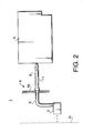
- Fig. 2 is a schematic view showing a main part of an ink jet printer according to a first embodiment of the present invention;
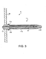
- Fig. 3 is a sectional view of a connecting pipe;
- Fig. 4 is a plan view of an ink container;
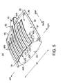
- Fig. 5 is a perspective view of the ink container of Fig. 4;
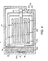
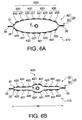
- Figs. 6A and 6B are front views of the ink container of Fig. 4;
- Figs. 7A, 7B and 7C are plan views showing the connecting process of the connecting pipe and the ink container;
- Figs. 8A, 8B are side views of the ink container of Fig. 4 and Fig. 8C is a schematic view showing a change in a capacity of the ink container;
- Fig. 9 is a plan view showing an ink container and a printing head according to a second embodiment of the present invention; and
- Fig. 10 is a enlarged view of a reservoir-mounting-portion of the printing head of Fig. 9.
-
- The first embodiment of the present invention is described.
- Fig. 2 is a schematic view showing a main part of an ink jet printer according to the first embodiment. The
ink jet printer 1 has aprinting head 2 which emerges ink droplets to a recording media R. Theprinting head 2 is mounted to a carriage (not shown) that is movable in the direction of the width of the recording media R. The carriage (not shown) has acartridge mounting portion 4 to which anink cartridge 3 is mounted. A connectingpipe 6 is provided to the mountingportion 4, which has a sharpen tip. The connectingpipe 6 is connected to theprinting head 2 via anintermediate pipe 5. - Fig. 3 is an enlarged view showing the connecting
pipe 6. The connectingpipe 6 is fixed to awall 4a of the mountingportion 4 via abushing 12. The connectingpipe 6 is covered by aflexible sheath 11. Theflexible sheath 11 has an accordion-folded-portion 11a which is extensible in the longitudinal direction of the connectingpipe 6. Atail portion 11c of theflexible sheath 11 is hooked on aflange portion 12a of thebushing 12, so that the flexible sheath does not drop out of thebushing 12. - When the connecting
pipe 6 is inserted into theink cartridge 3, the connectingpipe 6 pierces and penetrates atip 11b of theflexible sheath 11. Thetip 11b of theflexible sheath 11 is thicker than the other portion of theflexible sheath 11. With this, when the connecting pipe 6 (piercing thetip 11b) is removed from thetip 11b, a through-hole formed on thetip 11b is closed due to the elasticity of thetip 11b. It enables a user to repeatedly use theink cartridge 3. - Fig. 4 is a sectional view of the
ink cartridge 3. Theink cartridge 3 has acartridge case 21. Thecartridge case 21 has anopening 21a which is tightly sealed by aseal 22 made of an elastic material such as a rubber. Theseal 22 is fixed to the inner side of a wall around theopening 21. Theseal 22 is opened when pierced by the connecting pipe 6 (Fig. 3). - The interior of the
cartridge case 21 is divided into tworegions partition wall 21b. Thefirst region 23a (located behind theopening 21a) is filled with asponge member 25 in which ink can be impregnated. Thesecond region 23b accommodates anink container 24 detailed below. - Fig. 5 is a perspective view of the
ink container 24. As shown in Fig. 5, theink container 24 includes aflexible pack 30 in which ink can be reserved. Theflexible pack 30 is made of a rectangular sheet. The sheet is folded (bent) into two half sheets so that one of the half sheets lies on the other. Further, three ends of one of the half sheets are attached to opposing three ends of the other by means of heat seal. - In the description hereinafter, the half sheets of the
flexible pack 30 are respectively referred to as anupper sheet wall 31 and alower sheet walls 32 as shown in Fig. 5. The folded end is referred to as afront end 33. The (folded)front end 33 forms a plane surface that is substantially perpendicular to the upper andlower sheet walls flexible pack 30 are respectively referred to as aleft end 34, arear end 35, and aright end 36 as shown in Fig. 5. - The
ink container 24 further includes aspring member 40 provided to the outer surface of theflexible pack 30. Thespring member 40 has a plate form and extends over upper andlower sheet walls spring member 40 is defined as a U-shaped joiningsection 45. Opposing portions of the spring member 40 (fixed to thesheet walls 31 and 32) are defined as fixingportions lower fixing portion 400 is hidden beneath theflexible pack 30 in Fig. 5, thelower fixing portion 410 is constructed in a similar manner to theupper fixing portion 400. - The U-shaped joining
section 45 is located at the center of theflexible pack 30 in the direction of the width W of theflexible pack 30. Theupper fixing portion 400 has a symmetrical shape with respect to the center of theflexible pack 30 in the direction of the width W. Theupper fixing portion 400 includes two inner parts 420 (close to the center of the flexible pack 30) and two outer parts 430 (close to the side ends of the flexible pack 30). Theinner part 420 is Π-shaped and includes (1) afirst section 421 which extends frontward (in parallel to the side ends 34 and 36 of the flexible pack 30) to thefront end 33 from the U-shaped joiningsection 45, (2) asecond section 422 which extends sideways from the front end of thefirst section 421, and (3) athird section 423 which extends rearward (in parallel to the side ends 34 and 36 of the flexible pack 30) to therear end 35 from the side end of thesecond section 422. A connectingsection 425 is provided to the rear end of thethird section 423, which extends sideways. Theouter part 430 is Π-shaped and includes (1) afirst section 431 which extends frontward to thefront end 33 from the side end of the connectingsection 425, (2) asecond section 432 which extends sideways from the front end of thefirst section 431, and (3) athird section 433 which extends rearward to therear end 35 from the side end of thesection 432. Thesections upper sheet wall 31 of theflexible pack 30, by means of an adhesive agent or a double-sided-tape. - The
lower fixing portion 410 is attached to the outer surface of thelower sheet wall 32. Since the structure of thelower fixing portion 410 is the same as theupper fixing portion 400, the detailed description thereof is omitted. - The
spring member 40 is going to deform so that the fixingportions spring member 40 biases thesheet walls flexible pack 30 so that thesheet walls - As describe above, since the pressure in the
flexible pack 30 is negative, the ink leakage out of theink container 24 is prevented. Further, since thespring member 40 is provided to the outside of theflexible pack 30, the structure of theink container 24 is simple. Additionally, it is easy to manufacture theink container 24 by mass-production process. Further, since the fixingportion sheet walls sheet walls - Figs. 6A and 6B are front views of the
ink container 24. The local spring force of thespring member 40 has a distribution in the direction of the width W of theflexible pack 30. Particularly, the local spring force of thespring member 40 is strongest at the center of the direction of the width W. Further, the local spring force of thespring member 40 gradually decreases, according to the distance from the center in the direction of the width W. That is, the center portions of thesheet walls 31 and 32 (in the direction of the width W) are strongly biased outward, compared with the side portions of theflexible pack 30. - When ink is fully reserved in the
ink pack 30 as shown in Fig. 6A, theink pack 30 is entirely expanded. As the amount of ink decreases as shown in Fig. 6B, the interval between fixingportions flexible pack 30 is rapidly contracted, compared with the center portion of theflexible pack 30. Thus, the capacity of the center portion of theflexible pack 30 is larger than the side portions of theflexible pack 30. Accordingly, the remaining ink may easily gather at the center portion of theflexible pack 30. Since the connectingpipe 6 is inserted into the center portion of theflexible pack 30, ink can be effectively drawn by the connectingpipe 6. With such an arrangement, ink reserved in theflexible pack 30 can be fully used up. - Further, since the
sheet walls flexible pack 30, it promotes the tendency of the interval between thesheet walls flexible pack 30. - The mounting operation of the
ink cartridge 3 is described with reference to Figs. 7A, 7B and 7C. As shown in Fig. 7A, when theink cartridge 3 is not mounted to the mouthingportion 4 of the ink jet printer (not shown), the connectingpipe 6 is not inserted in theink container 3. In this state, the connectingpipe 6 is covered by theflexible sheath 11. With this, it is prevented that the connectingpipe 6 injures a finger of a user. Further, it is prevented that the connectingpipe 6 6 gets dried, and that dust and debris stick on the connectingpipe 6. - When the
ink cartridge 3 is mounted to the mountingportion 4, thesheath 11 is pushed by theink container 3 so that theaccordion portion 11a is contracted. With this, the connectingpipe 6 pierces the tip of thesheath 11a. Further, the connectingpipe 6 pierces theseal 22 to be inserted in theink cartridge 3. The interior of the ink cartridge is given a negative pressure, so that ink stored in the printing head 2 (Fig. 2) is sucked in theink cartridge 3 through the connectingpipe 6. The sucked ink is impregnated in thesponge 25 provided behind theseal 22. The printing head 2 (Fig. 2) then becomes empty. - Then, as shown in Fig. 7C, the connecting
pipe 6 pierces thefront end 33 of theflexible pack 30, so that the tip of the connectingpipe 6 is inserted in theflexible pack 30. With this, the printing head 2 (Fig. 2) and theink container 24 are connected so that ink can be supplied to theprinting head 2 from theink container 24. - The insertion of the connecting
pipe 6 into theflexible pack 30 is detailed with reference to Figs. 8A, 8B and 8C. The position where the connectingpipe 6 abuts thefront end 33 of theflexible pack 33 is the center of the fixingportions portions portions portions flexible pack 30 before and after the abutment of the connectingpipe 6. The increasing capacity C1 of theflexible pack 30 caused by the outward deformation of the upper andlower sheet walls front end 33. This is because the interval between the fixingportions pipe 6 pierces theflexible pack 30, the total capacity of theflexible pack 30 increases. In Fig. 8C, the decreasing capacity C2' caused by the inward deformation of the rear part of thesheet walls - As shown in Fig. 6A, the
front end 33 of theflexible pack 30 has an eye-shape such that the interval between thesheet walls front end 33 is relatively large, compared with the area of thefront end 33. Thus, the increasing capacity of theflexible pack 30 caused by the deformation of the upper andlower sheet walls front end 33. - As described above, since the total capacity of the
flexible pack 30 is increased when the connectingpipe 6 pierces theflexible pack 30, it increases the magnitude of negative pressure in theink container 24. This is advantageous in preventing the ink leakage out of theflexible pack 30 through a gap around the penetrating connectingpipe 6 and ink leakage through a nozzle of the printing head 2 (Fig. 2). - Since the portion to be pierced by the connecting
pipe 6 is located between the upper andlower sheet walls portions pipe 6 is easily converted to the buckling of the fixingportions spring member 40. Additionally, since thefront end 33 has a flat surface which is substantially perpendicular to the fixingportions pipe 6 is inserted into the center of the flat surface, it is easy to let the connectingpipe 6 pierce thefront end 33. - After the
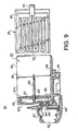
ink cartridge 3 is mounted to the mountingportion 4 of the ink jet printer as shown in Fig. 2, ink is introduced into the printing head 2 (through the connecting pipe 6) by a suction device provided in theprinting head 2. The negative pressure in theflexible pack 30 reaches to theprinting head 2, so that ink does not unintentionally drop out of theprinting head 2 on starting a printing operation of the ink jet printer. - Fig. 9 is a sectional view of a modification of the first embodiment. As shown in Fig. 9, an
ink jet printer 51 has aprinting head 52 and acarriage 53 that carries theprinting head 52. In this modification, theink container 24 is directly mounted to a mountingportion 55 of thecarriage 53. The mountingportion 55 is made of synthetic resin, and includes afloor 58 and adouble wall 57 formed on thefloor 58. Thedouble wall 57 includes first andsecond walls ink chamber 56 formed between thewalls side walls floor 58. Thefloor 58, thedouble wall 57 and theside walls recess 61 which receives theink container 24. - A connecting
pipe 62 is provided to thedouble wall 57, which is arranged to pierce theink container 24 when theink container 24 is mounted to therecess 61. The connectingpipe 62 extends from thechamber 56 to therecess 61, supported by thesecond wall 57b via abushing 63. Anink supply hole 64 is formed at the lower part of thechamber 56. Theprinting head 52 is mounted to theink supply hole 64 viaadapters printing head 52 is covered bycover members - When the
ink container 24 is mounted to therecess 61, the connectingpipe 62 pierces thefront end 33 of theink container 24. With this, theprinting head 52 and theink container 24 are connected with each other via the connectingpipe 62, thechamber 56 andink supply hole 64. After theink container 24 is mounted to therecess 61, ink is introduced into the printing head 2 (through the connectingpipe 62, thechamber 56 and ink supply hole 64) by a suction device provided in theprinting head 2. - Since the pressure in the
ink container 24 is negative, the leakage of ink out of theink container 24 is prevented. Further, since the negative pressure in theflexible pack 30 reaches to theprinting head 2, ink does not unintentionally drop out of theprinting head 2 on starting a printing operation of the ink jet printer. - Although the structure and operation of the ink container and the ink jet printer are described herein with respect to the preferred embodiment, many modifications and changes can be made without departing from the scope of the appended claims.
Claims (18)
- An ink container (24) comprising:characterised in thata flexible pack (30) in which ink can be reserved, said flexible pack (30) having two sheet walls (31,32) opposing with each other; anda biasing arrangement (40) which biases said opposing sheet walls (31,32) away from each other thereby to increase a capacity of said flexible pack (30), causing a negative pressure in said flexible pack (30) ;
said biasing arrangement comprises a spring member (40) in a plate form, which extends over said two opposing sheet walls (31,32) of said flexible pack (30). - The ink container according to claim 1, wherein said flexible pack (30) has a certain width and a certain length,
said spring member (40) comprising :a U-shaped joining section (45) located at a center of said flexible pack (30) in a direction of said width; andfixing portions (400,410) fixed to said two opposing sheet walls (31,32), said fixing portions (400,410) extending in a direction of said width toward lateral sides of said flexible pack (30). - The ink container according to claim 2, wherein said spring member (40) is so constituted that a local spring force is stronger at a center thereof in said width direction than at a side thereof in said width direction.
- The ink container according to claim 2 or 3, said spring member (40) comprising a band (420,430) extending in a zigzag manner so that said band extends in a direction of said width and in a direction of said length.
- The ink container according to any preceding claim, wherein, when said spring member (40) is urged in one direction, opposing portions of said spring member (40) deform away from each other so as to increase a capacity of said flexible pack.
- The ink container according to claim 5, wherein said flexible pack has an end surface (33) formed at an end thereof in said one direction.
- The ink container according to claim 5 or 6, wherein said spring member (40) has curvatures so that an interval between opposing portions of said spring member (40) is the largest at center portions in said one direction.
- The ink container according to any preceding claim, wherein said flexible pack (30) is made by folding a rectangular sheet so that a half of said sheet lies on the other, and by attaching opposing ends of said halves.
- The ink container according to claim 1 wherein said flexible pack (30) has a certain width and a certain length; and
wherein said biasing arrangement (40) is so constituted that a local spring force is stronger at a center thereof in said width direction than at a side thereof in said width direction. - The ink container according to claim 1 wherein said flexible pack further has an end surface (33); and
when said end surface (33) is urged in one direction, at least a part of said biasing arrangement (40) is deformed so as to further increase the capacity of said flexible pack (30). - The ink container according to claim 10, wherein an increasing capacity of said flexible pack (30) caused by the deformation of said biasing arrangement (40) is larger than a decreasing capacity of said flexible pack (30) caused by the inward deformation of said end surface (33).
- The ink container according to claim 10 or 11, wherein said spring member (40) has curvatures so that an interval between opposing portions of said spring member (40) is the largest at center portions in said one direction.
- The ink container according to claim 10, 11 or 12, wherein, when opposing portions of said spring member (40) are urged in said one direction, said opposing portions deform away from each other.
- The ink container according to claim 13, wherein said end surface (33) is a flat surface which is substantially perpendicular to said two sheet walls (31,32).
- The ink container according to claim 13 or 14, wherein said sheet walls (31,32) have a certain width that is perpendicular to said one direction; and
wherein said end surface (33) has an eye-shape such that an interval between said two sheet walls (31,32) at said end surface (33) is the largest at a centre thereof in a direction of said width, said interval decreasing according to a distance from said centre. - The ink container according to any one of claims 6 and 10 to 15, further comprising a connecting pipe (6) connecting said flexible pack (30) and a printing head (2) ;
wherein said connecting pipe (6) pierces said end surface (33), a pierced position on said end surface (33) being located between said two sheet walls (31,32). - An ink jet printer comprising:a printing head (2) which emerges ink droplets on a recording media;a carriage which carries said printing head (2) ;an ink container (24) according to any preceding claim;a mounting portion (4) formed on said carriage, to which said ink container (24) is mounted; anda connecting pipe (6) provided to said mounting portion (4), which is inserted into said flexible pack (30), said connecting pipe (6) connecting said flexible pipe (30) and said printing head (2).
- The ink jet printer according to claim 17, wherein said connecting pipe (6) pierces said end surface (33), a pierced position being located between said two sheet walls (31,32).
Priority Applications (1)
| Application Number | Priority Date | Filing Date | Title |
|---|---|---|---|
| EP02022020A EP1279512B1 (en) | 1997-08-20 | 1998-08-19 | Ink container for ink jet printer |
Applications Claiming Priority (6)
| Application Number | Priority Date | Filing Date | Title |
|---|---|---|---|
| JP22380697 | 1997-08-20 | ||
| JP223806/97 | 1997-08-20 | ||
| JP22380697A JP3887898B2 (en) | 1997-08-20 | 1997-08-20 | Ink container and ink jet recording apparatus using the same |
| JP225943/97 | 1997-08-22 | ||
| JP22594397A JP3915186B2 (en) | 1997-08-22 | 1997-08-22 | Ink container and ink jet recording apparatus using the same |
| JP22594397 | 1997-08-22 |
Related Child Applications (1)
| Application Number | Title | Priority Date | Filing Date |
|---|---|---|---|
| EP02022020A Division EP1279512B1 (en) | 1997-08-20 | 1998-08-19 | Ink container for ink jet printer |
Publications (3)
| Publication Number | Publication Date |
|---|---|
| EP0899112A2 EP0899112A2 (en) | 1999-03-03 |
| EP0899112A3 EP0899112A3 (en) | 2000-05-17 |
| EP0899112B1 true EP0899112B1 (en) | 2003-07-23 |
Family
ID=26525696
Family Applications (2)
| Application Number | Title | Priority Date | Filing Date |
|---|---|---|---|
| EP98306647A Expired - Lifetime EP0899112B1 (en) | 1997-08-20 | 1998-08-19 | Inkjet printer and ink container used therein |
| EP02022020A Expired - Lifetime EP1279512B1 (en) | 1997-08-20 | 1998-08-19 | Ink container for ink jet printer |
Family Applications After (1)
| Application Number | Title | Priority Date | Filing Date |
|---|---|---|---|
| EP02022020A Expired - Lifetime EP1279512B1 (en) | 1997-08-20 | 1998-08-19 | Ink container for ink jet printer |
Country Status (4)
| Country | Link |
|---|---|
| US (1) | US6227662B1 (en) |
| EP (2) | EP0899112B1 (en) |
| DE (2) | DE69831883T2 (en) |
| HK (1) | HK1049645B (en) |
Cited By (2)
| Publication number | Priority date | Publication date | Assignee | Title |
|---|---|---|---|---|
| US8007065B2 (en) | 2004-01-21 | 2011-08-30 | Silverbrook Research Pty Ltd | Printer control circuitry for reading ink information from a refill unit |
| US8079664B2 (en) | 2004-01-21 | 2011-12-20 | Silverbrook Research Pty Ltd | Printer with printhead chip having ink channels reinforced by transverse walls |
Families Citing this family (12)
| Publication number | Priority date | Publication date | Assignee | Title |
|---|---|---|---|---|
| JPH11240171A (en) * | 1997-12-22 | 1999-09-07 | Oki Data Corp | Ink storage container |
| US6505924B2 (en) | 1998-09-30 | 2003-01-14 | Brother Kogyo Kabushiki Kaisha | Ink cartridge |
| US6220702B1 (en) | 1998-12-24 | 2001-04-24 | Seiko Epson Corporation | Ink bag for ink jet type recording apparatus and package suitable for packing such ink bag |
| US6364474B1 (en) * | 1999-09-10 | 2002-04-02 | Industrial Technology Research Institute | Pressure control device |
| US6464346B2 (en) * | 1999-10-29 | 2002-10-15 | Hewlett-Packard Company | Ink containment and delivery techniques |
| ATE326347T1 (en) * | 2000-01-21 | 2006-06-15 | Seiko Epson Corp | INK CARTRIDGE AND INKJET PRINTING DEVICE HAVING SUCH AN INK CARTRIDGE |
| WO2002058024A1 (en) * | 2001-01-19 | 2002-07-25 | Fujitsu Limited | Theft-prevention ink pack device, and treasure safe having the same |
| US6959984B2 (en) | 2001-08-14 | 2005-11-01 | Canon Kabushiki Kaisha | Liquid container and inkjet cartridge |
| JP2004083621A (en) | 2002-08-22 | 2004-03-18 | Brother Ind Ltd | Water-based ink for ink-jet recording |
| US7367650B2 (en) | 2004-01-21 | 2008-05-06 | Silverbrook Research Pty Ltd | Printhead chip having low aspect ratio ink supply channels |
| US7524016B2 (en) | 2004-01-21 | 2009-04-28 | Silverbrook Research Pty Ltd | Cartridge unit having negatively pressurized ink storage |
| JP4806616B2 (en) * | 2006-09-29 | 2011-11-02 | 富士フイルム株式会社 | Ink cartridge and ink jet recording apparatus |
Family Cites Families (13)
| Publication number | Priority date | Publication date | Assignee | Title |
|---|---|---|---|---|
| GB2063175B (en) | 1979-11-06 | 1984-02-15 | Shinshu Seiki Kk | Ink jet printer |
| JPS59204566A (en) | 1983-05-09 | 1984-11-19 | Ricoh Co Ltd | Ink bag of ink cartridge in one-demand type ink jet printer |
| JPS62225352A (en) * | 1986-03-27 | 1987-10-03 | Nec Corp | Ink-supplying mechanism for ink jet printer |
| JPH023321A (en) * | 1988-06-17 | 1990-01-08 | Canon Inc | Ink cartridge |
| US5325119A (en) * | 1992-08-12 | 1994-06-28 | Hewlett-Packard Company | Variable rate spring ink pressure regulator for a thermal ink jet printer |
| US5574490A (en) | 1992-08-12 | 1996-11-12 | Hewlett-Packard Company | Ink jet hard copy apparatus ink cartridge |
| CA2093971A1 (en) * | 1992-08-12 | 1994-02-13 | Tofigh Khodapanah | Ink pressure regulator for a thermal ink jet printer |
| JPH06183023A (en) * | 1992-12-21 | 1994-07-05 | Canon Inc | Ink cartridge and ink jet recorder |
| US5426459A (en) * | 1992-12-22 | 1995-06-20 | Hewlett-Packard Company | Combined filter/aircheck valve for thermal ink-jet pen |
| JPH0752399A (en) | 1993-08-11 | 1995-02-28 | Canon Inc | Ink tank |
| JP3450916B2 (en) | 1993-12-21 | 2003-09-29 | ヒューレット・パッカード・カンパニー | Printer ink cartridges |
| US5691755A (en) | 1994-04-18 | 1997-11-25 | Hewlett-Packard Company | Collapsible ink cartridge |
| US5751320A (en) * | 1994-09-29 | 1998-05-12 | Hewlett-Packard Company | Ink recharger for inkjet print cartridge having sliding valve connectable to print cartridge |
-
1998
- 1998-08-19 DE DE69831883T patent/DE69831883T2/en not_active Expired - Lifetime
- 1998-08-19 DE DE69816541T patent/DE69816541T2/en not_active Expired - Lifetime
- 1998-08-19 EP EP98306647A patent/EP0899112B1/en not_active Expired - Lifetime
- 1998-08-19 US US09/136,764 patent/US6227662B1/en not_active Expired - Lifetime
- 1998-08-19 EP EP02022020A patent/EP1279512B1/en not_active Expired - Lifetime
-
2003
- 2003-03-10 HK HK03101703.3A patent/HK1049645B/en not_active IP Right Cessation
Cited By (9)
| Publication number | Priority date | Publication date | Assignee | Title |
|---|---|---|---|---|
| US8007065B2 (en) | 2004-01-21 | 2011-08-30 | Silverbrook Research Pty Ltd | Printer control circuitry for reading ink information from a refill unit |
| US8070266B2 (en) | 2004-01-21 | 2011-12-06 | Silverbrook Research Pty Ltd | Printhead assembly with ink supply to nozzles through polymer sealing film |
| US8075110B2 (en) | 2004-01-21 | 2011-12-13 | Silverbrook Research Pty Ltd | Refill unit for an ink storage compartment connected to a printhead through an outlet valve |
| US8079664B2 (en) | 2004-01-21 | 2011-12-20 | Silverbrook Research Pty Ltd | Printer with printhead chip having ink channels reinforced by transverse walls |
| US8079684B2 (en) | 2004-01-21 | 2011-12-20 | Silverbrook Research Pty Ltd | Ink storage module for a pagewidth printer cartridge |
| US8235502B2 (en) | 2004-01-21 | 2012-08-07 | Zamtec Limited | Printer print engine with cradled cartridge unit |
| US8251501B2 (en) | 2004-01-21 | 2012-08-28 | Zamtec Limited | Inkjet print engine having printer cartridge incorporating maintenance assembly and cradle unit incorporating maintenance drive assembly |
| US8376533B2 (en) | 2004-01-21 | 2013-02-19 | Zamtec Ltd | Cradle unit for receiving removable printer cartridge unit |
| US8485651B2 (en) | 2004-01-21 | 2013-07-16 | Zamtec Ltd | Print cartrdge cradle unit incorporating maintenance assembly |
Also Published As
| Publication number | Publication date |
|---|---|
| HK1049645B (en) | 2006-01-13 |
| DE69816541D1 (en) | 2003-08-28 |
| EP0899112A2 (en) | 1999-03-03 |
| DE69831883T2 (en) | 2006-07-13 |
| DE69831883D1 (en) | 2005-11-17 |
| US6227662B1 (en) | 2001-05-08 |
| EP0899112A3 (en) | 2000-05-17 |
| EP1279512A1 (en) | 2003-01-29 |
| DE69816541T2 (en) | 2004-04-15 |
| HK1049645A1 (en) | 2003-05-23 |
| EP1279512B1 (en) | 2005-10-12 |
Similar Documents
| Publication | Publication Date | Title |
|---|---|---|
| EP0899112B1 (en) | Inkjet printer and ink container used therein | |
| JP3733266B2 (en) | Liquid storage container | |
| US6505924B2 (en) | Ink cartridge | |
| KR100190414B1 (en) | Ink container and manufacturing method for the same | |
| JP3745161B2 (en) | Liquid storage container | |
| JP3667296B2 (en) | Ink tank | |
| EP0640482B1 (en) | Exchangeable ink cartridge | |
| US6736497B2 (en) | Ink cartridge and an ink-jet printer having the same | |
| EP0603516B1 (en) | Ink cartridge with ink reservoir and printhead | |
| US5886720A (en) | Ink cartridge | |
| US5917527A (en) | Ink-jet pen with near net size porous member | |
| JP6372369B2 (en) | Liquid container | |
| EP1519095A2 (en) | Tube fixing structure and fixing member used therefor | |
| EP0709209B1 (en) | Ink-container with porous member cover slip | |
| EP2567820B1 (en) | Ink cartridge and inkjet printer | |
| JP3887898B2 (en) | Ink container and ink jet recording apparatus using the same | |
| JP4347278B2 (en) | Cap used for liquid container | |
| CN220883798U (en) | Ink box with head | |
| CN117915804A (en) | Distributor for razor blade holder | |
| JP3687706B2 (en) | Printer and ink tank | |
| US9050815B2 (en) | Liquid holding container and liquid supply system | |
| JPH08183184A (en) | Ink tank, ink jet cartridge and ink jet recording device | |
| JP3768985B2 (en) | Ink tank, recording head and recording apparatus using the ink tank | |
| JP4018556B2 (en) | Ink tank | |
| JP3915186B2 (en) | Ink container and ink jet recording apparatus using the same |
Legal Events
| Date | Code | Title | Description |
|---|---|---|---|
| PUAI | Public reference made under article 153(3) epc to a published international application that has entered the european phase |
Free format text: ORIGINAL CODE: 0009012 |
|
| AK | Designated contracting states |
Kind code of ref document: A2 Designated state(s): DE GB SE |
|
| AX | Request for extension of the european patent |
Free format text: AL;LT;LV;MK;RO;SI |
|
| PUAL | Search report despatched |
Free format text: ORIGINAL CODE: 0009013 |
|
| AK | Designated contracting states |
Kind code of ref document: A3 Designated state(s): AT BE CH CY DE DK ES FI FR GB GR IE IT LI LU MC NL PT SE |
|
| AX | Request for extension of the european patent |
Free format text: AL;LT;LV;MK;RO;SI |
|
| 17P | Request for examination filed |
Effective date: 20000915 |
|
| AKX | Designation fees paid |
Free format text: DE GB SE |
|
| 17Q | First examination report despatched |
Effective date: 20010731 |
|
| GRAG | Despatch of communication of intention to grant |
Free format text: ORIGINAL CODE: EPIDOS AGRA |
|
| GRAG | Despatch of communication of intention to grant |
Free format text: ORIGINAL CODE: EPIDOS AGRA |
|
| GRAG | Despatch of communication of intention to grant |
Free format text: ORIGINAL CODE: EPIDOS AGRA |
|
| GRAH | Despatch of communication of intention to grant a patent |
Free format text: ORIGINAL CODE: EPIDOS IGRA |
|
| GRAH | Despatch of communication of intention to grant a patent |
Free format text: ORIGINAL CODE: EPIDOS IGRA |
|
| GRAA | (expected) grant |
Free format text: ORIGINAL CODE: 0009210 |
|
| AK | Designated contracting states |
Designated state(s): DE GB SE |
|
| REG | Reference to a national code |
Ref country code: GB Ref legal event code: FG4D |
|
| REG | Reference to a national code |
Ref country code: SE Ref legal event code: TRGR |
|
| REF | Corresponds to: |
Ref document number: 69816541 Country of ref document: DE Date of ref document: 20030828 Kind code of ref document: P |
|
| PLBE | No opposition filed within time limit |
Free format text: ORIGINAL CODE: 0009261 |
|
| STAA | Information on the status of an ep patent application or granted ep patent |
Free format text: STATUS: NO OPPOSITION FILED WITHIN TIME LIMIT |
|
| 26N | No opposition filed |
Effective date: 20040426 |
|
| PGFP | Annual fee paid to national office [announced via postgrant information from national office to epo] |
Ref country code: GB Payment date: 20170725 Year of fee payment: 20 Ref country code: DE Payment date: 20170825 Year of fee payment: 20 |
|
| PGFP | Annual fee paid to national office [announced via postgrant information from national office to epo] |
Ref country code: SE Payment date: 20170810 Year of fee payment: 20 |
|
| REG | Reference to a national code |
Ref country code: DE Ref legal event code: R071 Ref document number: 69816541 Country of ref document: DE |
|
| REG | Reference to a national code |
Ref country code: GB Ref legal event code: PE20 Expiry date: 20180818 |
|
| REG | Reference to a national code |
Ref country code: SE Ref legal event code: EUG |
|
| PG25 | Lapsed in a contracting state [announced via postgrant information from national office to epo] |
Ref country code: GB Free format text: LAPSE BECAUSE OF EXPIRATION OF PROTECTION Effective date: 20180818 |