EP0899895A1 - Coherent demodulation of spread spectum signals without pilot signal - Google Patents
Coherent demodulation of spread spectum signals without pilot signal Download PDFInfo
- Publication number
- EP0899895A1 EP0899895A1 EP98401948A EP98401948A EP0899895A1 EP 0899895 A1 EP0899895 A1 EP 0899895A1 EP 98401948 A EP98401948 A EP 98401948A EP 98401948 A EP98401948 A EP 98401948A EP 0899895 A1 EP0899895 A1 EP 0899895A1
- Authority
- EP
- European Patent Office
- Prior art keywords
- signal
- phase
- summed
- phase shift
- channel
- Prior art date
- Legal status (The legal status is an assumption and is not a legal conclusion. Google has not performed a legal analysis and makes no representation as to the accuracy of the status listed.)
- Granted
Links
Images


Classifications
-
- H—ELECTRICITY
- H04—ELECTRIC COMMUNICATION TECHNIQUE
- H04L—TRANSMISSION OF DIGITAL INFORMATION, e.g. TELEGRAPHIC COMMUNICATION
- H04L27/00—Modulated-carrier systems
- H04L27/18—Phase-modulated carrier systems, i.e. using phase-shift keying
- H04L27/22—Demodulator circuits; Receiver circuits
- H04L27/233—Demodulator circuits; Receiver circuits using non-coherent demodulation
- H04L27/2332—Demodulator circuits; Receiver circuits using non-coherent demodulation using a non-coherent carrier
-
- H—ELECTRICITY
- H04—ELECTRIC COMMUNICATION TECHNIQUE
- H04B—TRANSMISSION
- H04B1/00—Details of transmission systems, not covered by a single one of groups H04B3/00 - H04B13/00; Details of transmission systems not characterised by the medium used for transmission
- H04B1/69—Spread spectrum techniques
- H04B1/707—Spread spectrum techniques using direct sequence modulation
-
- H—ELECTRICITY
- H04—ELECTRIC COMMUNICATION TECHNIQUE
- H04L—TRANSMISSION OF DIGITAL INFORMATION, e.g. TELEGRAPHIC COMMUNICATION
- H04L27/00—Modulated-carrier systems
- H04L27/0014—Carrier regulation
- H04L2027/0024—Carrier regulation at the receiver end
- H04L2027/0026—Correction of carrier offset
- H04L2027/003—Correction of carrier offset at baseband only
-
- H—ELECTRICITY
- H04—ELECTRIC COMMUNICATION TECHNIQUE
- H04L—TRANSMISSION OF DIGITAL INFORMATION, e.g. TELEGRAPHIC COMMUNICATION
- H04L27/00—Modulated-carrier systems
- H04L27/0014—Carrier regulation
- H04L2027/0044—Control loops for carrier regulation
- H04L2027/0053—Closed loops
- H04L2027/0057—Closed loops quadrature phase
Definitions
- the field of the invention is that of spread digital transmissions of frequency, including, but not limited to, CDMA transmissions (for "Code Division Multiple Access” in English).
- CDMA Code Division Multiple Access
- the CDMA technique which consists in multiplying a source signal (included in a common frequency band) by a specific code, constitutes an application of frequency spreading.
- the emission of spread frequency modulation devices In such transmission systems, the emission of spread frequency modulation devices.
- the latter subject to input signals (or source signals) a frequency spreading then a quadrature modulation, so as to obtain signals to be transmitted.
- D bit rate
- N the spreading factor
- the invention relates more precisely to coherent demodulation devices, of the type intended to regenerate, from received signals, the input signals of the devices aforementioned frequency spread modulation.
- a complex input signal at rate D results from the passage of a real signal at rate 2.D in a type 1 to 2 serial / parallel converter.
- the invention has numerous applications, such as, for example, cellular digital radio communications.
- single-channel transmissions are typically used in the case of an uplink channel (mobile station to base station), where the mobile station is supposed to be satisfied with the existence of a single channel of communication to the base station.
- uplink channel mobile station to base station
- the base station can separate the signals from the different mobile stations.
- multichannel transmissions are typically used in the case of a downlink (base station to station mobile), where the base station must communicate with several mobile stations.
- the signal transmitted by the base station is then an aggregate of several channels, broadcast to all mobile stations.
- These channels are separated from each other by the use of codes, called “orthogonal" insofar as they allow a receiver of a station mobile to extract the channel intended for it without being bothered by the presence of others canals.
- a demodulation device (or receiver) has the task of regenerating the input signal (s) (or signal (ux) source) to from the signal it receives.
- the received signal corresponds to the transmitted signal affected by various disturbances.
- the demodulated signal resulting is a complex signal affected by phase rotation. This rotation corresponds precisely at phase shift.
- the phase shift evolves over time, it is a dynamic phenomenon. The treatment of this phase shift varies depending on whether it is a single-channel or multi-channel transmission.
- non-coherent demodulation In the case of a single-channel type transmission, a non-coherent demodulation, which has consequences for both the receiver and on the transmitter.
- the principle of non-coherent demodulation is to choose a sequence transmitted which can be interpreted on reception without the knowledge of the phase shift brought through the channel.
- the invention particularly aims to overcome these various drawbacks of the state of the art.
- one of the objectives of the present invention is to provide a single-channel coherent demodulation device, usable in the case of transmission single-channel type, and having better performance than the devices aforementioned classics of non-coherent demodulation.
- the invention also aims to provide a multichannel device for coherent demodulation, usable in the case of a multichannel type transmission, and having better performance than the aforementioned conventional devices of coherent demodulation with pilot.
- Another object of the invention is to provide such single-channel devices and multichannel coherent demodulation, allowing to estimate and correct the phase shift induced in particular by the propagation medium, without making any hypothesis on the signals transmitted, and in particular without transmitting a pilot.
- An additional objective of the invention is to provide a reception assembly to multiple paths of diversity, which retains the advantages linked to the devices (single-channel or multi-channel) included in this set.
- the general principle of the invention therefore consists in using a coherent unmanned demodulation, which is without influence on the transmitter and improves the demodulation performance.
- a coherent unmanned demodulation which is without influence on the transmitter and improves the demodulation performance.
- the coherent demodulation of the invention is carried out without any knowledge of the transmitted signal. Indeed, the estimate of the phase shift is obtained by producing a signed value from the argument of the summed signal. More precisely, we apply to the summed signal a predetermined function, itself based on a modulo function, allowing to bring back the argument of this summed signal in a range around zero.
- the estimate of the phase shift is used in a control loop of the phase (for example first order). So the system converges to a zero error (i.e. towards a perfect correction of the phase shift).
- phase ambiguity is a known phenomenon in non-spreading systems of frequency (or not CDMA), where it is linked to the recovery of the carrier. Therefore, to resolve such phase ambiguity, we already know solutions that can be applied here. In any event, even if the solution adopted to resolve the ambiguity phase leads to a slight degradation in performance, this slight degradation is very low compared to that which would be obtained from the use of a demodulation not consistent.
- the general principle of the invention therefore consists in using a coherent demodulation without a pilot.
- a coherent demodulation with pilot which is used in this case.
- the multichannel device of the invention differs from the single-channel device aforementioned essentially in that an estimate of the phase shift is carried out on each summed signal specific to a given channel. From all these estimates, we calculate a average estimate, which makes it possible to globally correct the phase of the signal received. In in addition, a residual static phase ambiguity must be removed on each summed signal specific to a given channel.
- x is equal to 1 or 2 depending on whether said input signal is real or complex.
- said lifting means static residual phase ambiguity include means for differential coding / decoding.
- This variant applies in particular (but not exclusively) when the code the convolution used is not transparent to phase ambiguities. Indeed, if there is no transparency, the previous solution (differential coding / decoding) is inapplicable. In in this case, this non-transparency can be used to implement the present variant which does not itself present the phenomenon of multiplication of errors mentioned more high. Indeed, in the case where the residual phase ambiguity is not zero, the analysis the decoder output signal (for example comparison of the accumulated metric by relative to a predetermined threshold) makes it possible to detect whether the value chosen for the offset of phase is the right one. Trying the different phase shift values possible (trial and error process), the best offset value is determined, this which amounts to removing phase ambiguity.
- the reception assembly first determines a combined signal (resulting from the combination of the signals associated with the different paths) so that it presents a maximum gain, then removes the phase ambiguity on this combined signal.
- the gain measurement is done for example by measuring the absolute value.
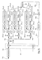
- Figures 1A and 1B correspond to the case single-channel transmission, respectively when the input signal is real (fig.1A) or complex (fig.1B).
- Figures 1C and 1D correspond to the case of a multichannel transmission, respectively when the input signals are real (fig.1C) or complex (fig.1D).
- the device 1 a of frequency spread modulation receives a single input signal 2 a , assumed to be digital and consisting of a binary train at the flow rate D.
- a spread signal 5 a is obtained by multiplication (3) of the input signal 2 a by a complex signal 4, noted (Pn + j Qn).
- Pn and Qn are two pseudo-random binary trains at the rate N * D, with N the spreading factor.
- the spread signal 5 a which is a complex signal at the rate N * D, is supplied to the two inputs of a modulator 6 with two carriers in quadrature.
- the signal at the output of the modulator 6, also at the flow rate N * D constitutes the signal to be transmitted 7 a .
- the device 1 b of frequency spread modulation differs from that of FIG. 1A only in that the signal entry 2 b is complex and not real.
- This complex input signal 2 b which is at bit rate D, results for example from the passage of a real source signal 8 b , at bit rate 2.D, in a series / parallel converter 9 of type 1 to 2.
- the frequency spread modulation device 1 c receives a plurality of input signals 2 c, 0 to 2 c, k .
- Each of these input signals 2 c, 0 to 2 c, k is multiplied (10) by a distinct orthogonal code H0 to Hk (Walsh code for example), so as to obtain a plurality of channels 11 c, 0 to 11 c, k .
- This plurality of channels 11 c, 0 to 11 c, k is grouped (12) on the same multichannel signal 13 c .
- a spread signal 5 c is obtained by multiplication (3) of the multichannel signal 13 c by a complex signal 4, denoted Pn + j Qn.
- the spread signal 5 c which is a complex signal at the rate N * D, is supplied to the two inputs of a modulator 6 with two carriers in quadrature.
- the signal at the output of the modulator 6, also at the rate N * D, constitutes the signal to be transmitted 7 c .
- the device 1 d of frequency spread modulation differs from that of FIG. 1 C only in that each of the signals d input 2 d, 0 to 2d, k is complex and not real.
- Each of the complex input signals 2 d, 0 to 2 d, k which is at bit rate D, results for example from the passage of an actual source signal among a plurality 8 d, 0 to 8 d, k , at bit rate 2 .D, in a type 1 to 2 series / parallel converter 9.
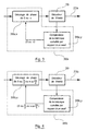
- FIGS. 2A to 2D four modes of production of a coherent demodulation device according to the invention, corresponding respectively to the four types of transmission in FIGS. 1A to 1D.
- the coherent demodulation device is of single-channel and receives a signal 14a resulting from the transmission through a given propagation medium, the signal 7 issued by the modulator 1 a in Figure 1A.
- the cumulative estimate 31 a can be subtracted from the phase of the despread signal 18 a (and not from the phase of the demodulated signal 16 a ), since the demodulation and despreading operations being linear, their order of execution can be reversed.
- the abovementioned analysis (38 a, y ) consists for example in comparing with respect to a predetermined threshold the cumulative metric of the signal 23. If the residual static phase shift is equal to 0, the Viterbi decoder operates normally. On the other hand, if the residual static phase shift is equal to ⁇ , there is an abnormally high cumulative metric at the output of the Viterbi decoder, greater than the level that they would reach in the maximum case of disturbance. After such an observation, the phase of the signal applied to the input of the Viterbi decoder is modified, by introducing an offset of ⁇ . Thus, the residual static phase ambiguity is removed.
- the means for removing the residual static phase ambiguity comprise differential coding / decoding means.
- the coherent demodulation device is of the single-channel type and receives a signal 14 b resulting from the transmission, through a given propagation medium, of the signal 7 b emitted by the modulation device 1b in Figure 1B.
- FIG. 4 a particular embodiment is presented of the means 38 b for removing the residual static phase ambiguity. It is easily understood that this embodiment is deduced directly from that presented above in relation to FIG. 3. Indeed, it suffices to replace the set of phase shift values ⁇ 0, ⁇ by the set ⁇ 0, ⁇ / 2, ⁇ , 3 ⁇ / 2 ⁇ .
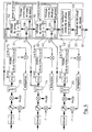
- the coherent demodulation device is of the multi-channel type and receives a signal 14 c resulting from the transmission, through a given propagation medium, of the signal 7 c emitted by the modulation device 1 c of Figure 1C.
- a despread signal 18 a is generated, after passing through a quadrature demodulator 15 and then through means 17 for despreading.
- the coherent demodulation device is of the multichannel type and receives a signal 14 d resulting from the transmission, through a given propagation medium, of the signal 7 d emitted by the modulation device 1 d in Figure 1D.
- This fourth embodiment is deduced from the third embodiment of the same way as the second embodiment is deduced from the first embodiment. It therefore does not require a specific description.
- the reception unit is for example a "RAKE” type receiver, which exploits the phenomenon of multiple paths to bring about a gain in diversity.
- the multipath phenomenon is present when the signal received by the receiver has crossed different paths associated with different electrical delays.
- the type receiver "RAKE” tries to realign temporally these different components, then to recombine in "phase” to obtain maximum gain. We assume here that the different diversity paths are already realigned temporally.
- the reception assembly comprises three single-channel type devices according to the second embodiment presented above (in relation to FIG. 2B).
- there are three diversity paths on the single channel each of the three coherent demodulation devices receiving a signal 14 b , 14 b ', 14 b "resulting from the transmission, through a propagation medium. given, of the signal 7 b emitted by the modulation device 1 b of FIG. 1B.
- the reception assembly therefore comprises three control loops of the identical to that of FIG. 2B, namely one for each of the three coherent demodulation.
- the reception assembly comprises means 50 for regenerating the input signal 2 b from the various summed signals S0 to S2 supplied by the summing means 20 of each of the three coherent demodulation devices. It will be noted that in FIG. 2B, the summed signal (to which each of these summed signals S0 to S2 corresponds) is referenced 21b . With perfect regeneration, the regenerated signal 51 is equal to the input signal 2 b (fig.1A).
- a group G1, G2 of means receives the combined signal S c generated by the preceding group of means only when the means 58 for controlling this preceding group of means have made their final choice.
- the principle is therefore generalizable to a larger number of summed signals (i.e. paths). Indeed, at each step, we add the path n to the sum of paths n-1 affected by a static phase shift chosen in ⁇ 0, ⁇ / 2, ⁇ , 3 ⁇ / 2 ⁇ .
- the receiving set includes any number ( ⁇ 2) of coherent unmanned demodulation.
- coherent demodulation devices included in the set of reception can be performed according to any one of the three other embodiments presented above (in relation to FIGS. 2A, 2C and 2D respectively).
Abstract
Description
Le domaine de l'invention est celui des transmissions numériques à étalement de fréquence, et notamment, mais non exclusivement, des transmissions CDMA (pour "Code Division Multiple Access" en langue anglaise). En effet, la technique CDMA, qui consiste à multiplier un signal source (compris dans une bande de fréquence commune) par un code spécifique, constitue une application de l'étalement de fréquence.The field of the invention is that of spread digital transmissions of frequency, including, but not limited to, CDMA transmissions (for "Code Division Multiple Access" in English). Indeed, the CDMA technique, which consists in multiplying a source signal (included in a common frequency band) by a specific code, constitutes an application of frequency spreading.
D'une façon générale, dans de tels systèmes de transmission, on utilise à l'émission des dispositifs de modulation à étalement de fréquence. Ces derniers font subir à des signaux d'entrée (ou signaux source) un étalement de fréquence puis une modulation en quadrature, de façon à obtenir des signaux à émettre. Classiquement (et c'est le cas dans la suite de la présente description), on considère que le ou chaque signal d'entrée présente un débit D, tandis que le signal à émettre et le signal reçu présentent chacun un débit N*D, où N est le facteur d'étalement.Generally, in such transmission systems, the emission of spread frequency modulation devices. The latter subject to input signals (or source signals) a frequency spreading then a quadrature modulation, so as to obtain signals to be transmitted. Conventionally (and this is the case in the remainder of this description), it is considered that the or each signal input has a bit rate D, while the signal to be sent and the signal received have each a flow rate N * D, where N is the spreading factor.
L'invention concerne plus précisément des dispositifs de démodulation cohérente, du type visant à régénérer, à partir de signaux reçus, les signaux d'entrée des dispositifs précités de modulation à étalement de fréquence.The invention relates more precisely to coherent demodulation devices, of the type intended to regenerate, from received signals, the input signals of the devices aforementioned frequency spread modulation.
Dans le cadre de la présente invention, on s'intéresse uniquement au cas d'un étalement de fréquence de type complexe (correspondant à l'utilisation de deux séquences d'étalement en quadrature). En effet, l'étalement réel (correspondant à l'utilisation d'une unique séquence d'étalement) présente un handicap de performances qui le rend sans intérêt.In the context of the present invention, we are only interested in the case of a frequency spreading of complex type (corresponding to the use of two sequences spreading in quadrature). Indeed, the actual spreading (corresponding to the use of a single spreading sequence) presents a performance handicap which makes it interest.
Généralement, on distingue deux familles de transmission à étalement de fréquence :
- les transmissions de type monocanal : le dispositif de modulation reçoit un unique signal d'entrée auquel il fait subir un étalement de fréquence puis une modulation en quadrature, de façon à générer le signal à émettre ;
- les transmissions de type multicanaux : le dispositif de modulation reçoit une pluralité de signaux d'entrée et fait subir à chacun d'entre eux une multiplication par un code orthogonal distinct (code de Walsh par exemple), de façon à obtenir une pluralité de canaux. Il regroupe cette pluralité de canaux sur un même signal multicanaux, auquel il fait subir un étalement de fréquence puis une modulation en quadrature, de façon à obtenir le signal à émettre.
- single-channel type transmissions: the modulation device receives a single input signal to which it undergoes frequency spreading then quadrature modulation, so as to generate the signal to be transmitted;
- multichannel type transmissions: the modulation device receives a plurality of input signals and makes each of them undergo a multiplication by a distinct orthogonal code (Walsh code for example), so as to obtain a plurality of channels . It combines this plurality of channels on the same multichannel signal, to which it undergoes frequency spreading then quadrature modulation, so as to obtain the signal to be transmitted.
Dans chacune de ces deux familles, on peut encore distinguer deux sous-familles,
correspondants respectivement aux cas où le(s) signal(ux) d'entrée est(sont) réel(s) ou
complexe(s). Généralement, un signal d'entrée complexe au débit D résulte du passage
d'un signal réel au débit 2.D dans un convertisseur série/parallèle de type 1 vers 2.In each of these two families, we can still distinguish two subfamilies,
corresponding respectively to cases where the input signal (s) is (are) real or
complex (s). Generally, a complex input signal at rate D results from the passage
of a real signal at rate 2.D in a
L'invention a de nombreuses applications, telles que par exemple les systèmes de radiocommunication numériques cellulaires.The invention has numerous applications, such as, for example, cellular digital radio communications.
En effet, dans les systèmes cellulaires, les transmissions monocanal sont typiquement utilisées dans le cas d'un canal montant (station mobile vers station de base), où la sation mobile est supposée se satisfaire de l'existence d'un canal unique de communication vers la station de base. On rappelle que plusieurs stations mobiles peuvent émettre chacune "en monocanal" dans la même bande de fréquence. En effet, comme elles utilisent des séquences d'étalement différentes, ou bien des phases différentes d'une séquence d'étalement commune, la station de base peut séparer les signaux émis par les différentes stations mobiles.Indeed, in cellular systems, single-channel transmissions are typically used in the case of an uplink channel (mobile station to base station), where the mobile station is supposed to be satisfied with the existence of a single channel of communication to the base station. Remember that several mobile stations can each transmit "single channel" in the same frequency band. Indeed, as they use different spreading sequences, or different phases of a common spreading sequence, the base station can separate the signals from the different mobile stations.
Par ailleurs, dans les systèmes cellulaires, les transmissions multicanaux sont typiquement utilisées dans le cas d'un canal descendant (station de base vers station mobile), où la station de base doit communiquer avec plusieurs stations mobiles. Le signal émis par la station de base est alors un agrégat de plusieurs canaux, diffusé vers l'ensemble des stations mobiles. Ces canaux sont séparés entre eux par l'utilisation de codes, dits "orthogonaux" dans la mesure où ils permettent à un récepteur d'une station mobile d'extraire le canal qui lui est destiné sans être gêné par la présence des autres canaux.Furthermore, in cellular systems, multichannel transmissions are typically used in the case of a downlink (base station to station mobile), where the base station must communicate with several mobile stations. The signal transmitted by the base station is then an aggregate of several channels, broadcast to all mobile stations. These channels are separated from each other by the use of codes, called "orthogonal" insofar as they allow a receiver of a station mobile to extract the channel intended for it without being bothered by the presence of others canals.
On notera cependant que la tendance actuelle, dans l'activité de normalisation des futurs réseaux cellulaires de type CDMA, est d'introduire la transmission multicanaux également dans le sens montant (station mobile vers station de base). Cette tendance est justifiée par la souplesse qui en résulte (en particulier pour les applications multimédia), ainsi que par la possibilité d'adopter une démodulation cohérente (qui est plus performante que la démodulation non cohérente devant être utilisée dans les dispositifs de réception multicanaux).It should be noted, however, that the current trend in the activity of standardization of future CDMA-type cellular networks, is to introduce multichannel transmission also in the uplink direction (mobile station to base station). This trend is justified by the resulting flexibility (in particular for multimedia applications), as well as by the possibility of adopting a coherent demodulation (which is more that the non-coherent demodulation to be used in the devices of multichannel reception).
On présente ci-dessous les techniques connues de démodulation (avec leurs inconvénients respectifs), pour chacune des deux familles de transmission précitées.The known demodulation techniques are presented below (with their respective disadvantages), for each of the two families of transmission mentioned above.
Auparavant, il convient de rappeler qu'un dispositif de démodulation (ou récepteur) a pour tâche de regénérer le ou les signaux d'entrée (ou signal(ux) source) à partir du signal qu'il reçoit. Le signal reçu correspond au signal émis affecté de diverses perturbations. On s'intéresse ici à la perturbation que constitue le déphasage. Après démodulation (par deux porteuses en quadrature) du signal reçu, le signal démodulé résultant est un signal complexe affecté d'une rotation de phase. Cette rotation correspond précisément au déphasage. On sait que le déphasage est dû au milieu de propagation ainsi qu'aux opérations de modulation et de démodulation (et notamment à l'asynchronisme entre les oscillateurs locaux alimentant le modulateur et le démodulateur). Le déphasage évolue dans le temps, c'est un phénomène dynamique. Le traitement de ce déphasage varie selon qu'il s'agit d'une transmission de type monocanal ou multicanaux.Beforehand, it should be remembered that a demodulation device (or receiver) has the task of regenerating the input signal (s) (or signal (ux) source) to from the signal it receives. The received signal corresponds to the transmitted signal affected by various disturbances. We are interested here in the disturbance that constitutes the phase shift. After demodulation (by two carriers in quadrature) of the received signal, the demodulated signal resulting is a complex signal affected by phase rotation. This rotation corresponds precisely at phase shift. We know that the phase shift is due to the propagation medium as well only to modulation and demodulation operations (and in particular to asynchronism between the local oscillators supplying the modulator and the demodulator). The phase shift evolves over time, it is a dynamic phenomenon. The treatment of this phase shift varies depending on whether it is a single-channel or multi-channel transmission.
Dans le cas d'une transmission de type monocanal, on utilise actuellement une démodulation non cohérente, ce qui a des conséquences aussi bien sur le récepteur que sur l'émetteur. Le principe de la démodulation non cohérente est de choisir une séquence transmise qui puisse être interprétée à la réception sans la connaissance du déphasage apporté par le canal.In the case of a single-channel type transmission, a non-coherent demodulation, which has consequences for both the receiver and on the transmitter. The principle of non-coherent demodulation is to choose a sequence transmitted which can be interpreted on reception without the knowledge of the phase shift brought through the channel.
Malheureusement, l'adoption de la démodulation non cohérente se paye par un handicap de performances.Unfortunately, the adoption of non-coherent demodulation is paid for by a performance handicap.
Dans le cas d'une transmission de type multicanaux, on utilise acuellement une démodulation cohérente, ce qui suppose la connaissance du déphasage variable introduit par les opérations de transmission, modulation et démodulation. La solution actuelle pour acquérir cette connaissance consiste à consacrer l'un des canaux à la transmission d'un pilote. En d'autres termes, on transmet généralement un tout "1" sur l'un des signaux d'entrée. Le récepteur exploite la présence du pilote pour faire l'estimation du canal et en particulier pour déterminer le déphasage apporté par le canal. Fort de cette connaissance, le récepteur peut alors annuler le déphasage.In the case of a multichannel type transmission, one currently uses a coherent demodulation, which supposes knowledge of the variable phase shift introduced by transmission, modulation and demodulation operations. The current solution for acquiring this knowledge consists in devoting one of the channels to the transmission of a pilot. In other words, we generally transmit a whole "1" on one of the signals entry. The receiver uses the pilot's presence to estimate the channel and particular to determine the phase shift brought by the channel. With this knowledge, the receiver can then cancel the phase shift.
Malheureusement, l'utilisation d'un pilote entraíne elle aussi une chute des performances du système. En effet, le canal qui porte le pilote n'est pas disponible pour transmettre des données utiles. En outre, on est souvent conduit à attribuer au canal pilote une puissance supérieure à celle d'un canal normal, en particulier lorsque les variations dynamiques sont rapides. Or, ce surplus de puissance émise n'étant pas porteur d'information, les performances de la liaison s'en trouvent dégradées.Unfortunately, the use of a pilot also leads to a drop in system performance. In fact, the channel carrying the pilot is not available for transmit useful data. In addition, we are often led to assign to the pilot channel higher power than a normal channel, especially when variations dynamics are fast. However, this surplus of emitted power not being carrier information, the performance of the link is degraded.
L'invention a notamment pour objectif de pallier ces différents inconvénients de l'état de la technique.The invention particularly aims to overcome these various drawbacks of the state of the art.
Plus précisément, l'un des objectifs de la présente invention est de fournir un dispositif monocanal de démodulation cohérente, utilisable dans le cas d'une transmission de type monocanal, et présentant de meilleures performances que les dispositifs classiques précités de démodulation non cohérente.More specifically, one of the objectives of the present invention is to provide a single-channel coherent demodulation device, usable in the case of transmission single-channel type, and having better performance than the devices aforementioned classics of non-coherent demodulation.
L'invention a également pour objectif de fournir un dispositif multicanaux de démodulation cohérente, utilisable dans le cas d'une transmission de type multicanaux, et présentant de meilleures performances que les dispositifs classiques précités de démodulation cohérente avec pilote.The invention also aims to provide a multichannel device for coherent demodulation, usable in the case of a multichannel type transmission, and having better performance than the aforementioned conventional devices of coherent demodulation with pilot.
Un autre objectif de l'invention est de fournir de tels dispositifs monocanal et multicanaux de démodulation cohérente, permettant d'estimer et de corriger le déphasage induit notamment par le milieu de propagation, sans faire d'hypothèse sur les signaux transmis, et en particulier sans transmettre de pilote.Another object of the invention is to provide such single-channel devices and multichannel coherent demodulation, allowing to estimate and correct the phase shift induced in particular by the propagation medium, without making any hypothesis on the signals transmitted, and in particular without transmitting a pilot.
Un objectif complémentaire de l'invention est de fournir un ensemble de réception à plusieurs chemins de diversité, qui conserve les avantages liés aux dispositifs (monocanal ou multicanaux) compris dans cet ensemble.An additional objective of the invention is to provide a reception assembly to multiple paths of diversity, which retains the advantages linked to the devices (single-channel or multi-channel) included in this set.
Ces différents objectifs, ainsi que d'autres qui apparaítront par la suite, sont
atteints selon l'invention à l'aide d'un dispositif monocanal de démodulation cohérente,
du type visant à régénérer, à partir d'un signal reçu, un signal d'entrée d'un dispositif
monocanal de modulation à étalement complexe d'ordre N, ledit dispositif monocanal de
modulation à étalement complexe faisant subir audit signal d'entrée un étalement
complexe puis une modulation en quadrature, de façon à obtenir un signal à émettre, ledit
signal d'entrée présentant un débit D, ledit signal à émettre et ledit signal reçu présentant
chacun un débit N*D,
caractérisé en ce qu'il comprend notamment :
- des moyens de démodulation en quadrature, générant un signal démodulé, au débit N*D, à partir dudit signal reçu ;
- des moyens de désétalement complexe, générant un signal désétalé, au débit N*D, à partir dudit signal démodulé ;
- des moyens de sommation sur N échantillons, générant un signal sommé, au débit D, à partir dudit signal désétalé ;
- une boucle d'estimation et de correction du déphasage induit sur ledit signal
démodulé, ladite boucle comprenant :
- des moyens de prise de l'argument dudit signal sommé ;
- des moyens d'application d'une fonction prédéterminée permettant de ramener l'argument du signal sommé dans une plage [- π/(2.x), π/(2.x)[, où x est égal à 1 ou 2 selon que ledit signal d'entrée est réel ou complexe, le résultat de l'application de ladite fonction prédéterminée audit argument du signal sommé constituant une estimation dudit déphasage ;
- des moyens de soustraction de ladite estimation du déphasage à la phase dudit signal démodulé ou à celle dudit signal désétalé ;
- des moyens de regénération dudit signal d'entrée à partir dudit signal sommé, comprenant eux-mêmes des moyens de levée d'une ambiguïté statique résiduelle de phase induite par l'application de ladite fonction prédéterminée.
characterized in that it comprises in particular:
- quadrature demodulation means, generating a demodulated signal, at the rate N * D, from said received signal;
- complex despreading means, generating a despread signal, at the rate N * D, from said demodulated signal;
- means for summing on N samples, generating a summed signal, at the rate D, from said despread signal;
- a loop for estimating and correcting the phase shift induced on said demodulated signal, said loop comprising:
- means for taking the argument of said summed signal;
- means for applying a predetermined function making it possible to bring the argument of the summed signal into a range [- π / (2.x), π / (2.x) [, where x is equal to 1 or 2 according to that said input signal is real or complex, the result of the application of said predetermined function to said argument of the summed signal constituting an estimate of said phase shift;
- means for subtracting said estimate of the phase shift from the phase of said demodulated signal or from that of said despread signal;
- means for regenerating said input signal from said summed signal, themselves comprising means for removing a residual static phase ambiguity induced by the application of said predetermined function.
Dans le cas d'une transmission de type monocanal, le principe général de l'invention consiste donc à utiliser une démodulation cohérente sans pilote, qui est sans influence sur l'émetteur et permet d'améliorer les performances de la démodulation. On rappelle que dans l'art antérieur, c'est une démodulation non cohérente qui est utilisée dans ce cas.In the case of a single-channel transmission, the general principle of the invention therefore consists in using a coherent unmanned demodulation, which is without influence on the transmitter and improves the demodulation performance. We recalls that in the prior art, it is a non-coherent demodulation which is used in that case.
Il est important de noter que la démodulation cohérente de l'invention est effectuée sans aucune connaissance du signal transmis. En effet, l'estimation du déphasage est obtenue en produisant une valeur signée à partir de l'argument du signal sommé. Plus précisément, on applique au signal sommé une fonction prédéterminée, elle-même basée sur une fonction modulo, permettant de ramener l'argument de ce signal sommé dans une plage autour de zéro.It is important to note that the coherent demodulation of the invention is carried out without any knowledge of the transmitted signal. Indeed, the estimate of the phase shift is obtained by producing a signed value from the argument of the summed signal. More precisely, we apply to the summed signal a predetermined function, itself based on a modulo function, allowing to bring back the argument of this summed signal in a range around zero.
L'estimation du déphasage est utilisée dans une boucle d'asservissement de la phase (par exemple du premier ordre). Ainsi, le système converge vers une erreur nulle (c'est-à-dire vers une correction parfaite du déphasage).The estimate of the phase shift is used in a control loop of the phase (for example first order). So the system converges to a zero error (i.e. towards a perfect correction of the phase shift).
On notera que l'application de la fonction prédéterminée introduit en contrepartie une ambiguïté statique résiduelle de phase, qu'il convient de lever. Toutefois, une telle ambiguïté de phase est un phénomène connu dans les systèmes sans étalement de fréquence (ou non CDMA), où il est lié à la récupération de la porteuse. Par conséquent, pour lever une telle ambiguïté de phase, on connaít déjà des solutions qui peuvent être appliquées ici. En tout état de cause, même si la solution adoptée pour lever l'ambiguïté de phase entraíne une légère dégradation des performances, cette légère dégradation est très faible en comparaison de celle qu'apporterait l'utilisation d'une démodulation non cohérente.Note that the application of the predetermined function introduced in return a residual static phase ambiguity, which should be removed. However, such phase ambiguity is a known phenomenon in non-spreading systems of frequency (or not CDMA), where it is linked to the recovery of the carrier. Therefore, to resolve such phase ambiguity, we already know solutions that can be applied here. In any event, even if the solution adopted to resolve the ambiguity phase leads to a slight degradation in performance, this slight degradation is very low compared to that which would be obtained from the use of a demodulation not consistent.
L'invention concerne également un dispositif multicanaux de démodulation cohérente, du type visant à régénérer, à partir d'un signal reçu, une pluralité de signaux d'entrée d'un dispositif multicanaux de modulation à étalement complexe d'ordre N, ledit dispositif multicanaux de modulation faisant subir à chacun desdits signaux d'entrée une multiplication par un code orthogonal distinct, de façon à obtenir une pluralité de canaux, ladite pluralité de canaux étant regroupés sur un même signal multicanaux, ledit signal multicanaux subissant un étalement complexe puis une modulation en quadrature, de façon à obtenir un signal à émettre, chacun desdits signaux d'entrée présentant un débit D, ledit signal à émettre et ledit signal reçu présentant chacun un débit N*D, ledit dispositif multicanaux de démodulation cohérente comprenant notamment :
- des moyens de démodulation en quadrature, générant un signal démodulé, au débit N*D, à partir dudit signal reçu ;
- des moyens de désétalement complexe, générant un signal désétalé, au débit N*D, à partir dudit signal démodulé,
- une pluralité de branches de traitement, chacune associée à un canal donné parmi
ladite pluralité et comprenant notamment :
- des moyens de multiplication dudit signal désétalé par le code orthogonal propre audit canal donné, de façon à obtenir un signal désétalé propre audit canal donné, au débit N*D ;
- des moyens de sommation sur N échantillons, générant un signal sommé propre audit canal donné, au débit D, à partir dudit signal désétalé propre audit canal donné ;
- une boucle d'estimation et de correction du déphasage induit sur ledit signal
démodulé, ladite boucle comprenant :
- dans chacune desdites branches de traitement :
- des moyens de prise de l'argument dudit signal sommé propre audit canal donné ;
- des moyens d'application d'une fonction prédéterminée permettant
de ramener l'argument du signal sommé propre audit canal donné
dans une plage [- π/(2.x), π/(2.x)[, où x est égal à 1
ou 2 selon que ledit signal d'entrée dudit canal donné est réel ou complexe, le résultat de l'application de ladite fonction prédéterminée audit argument du signal sommé propre audit canal donné constituant une estimation dudit déphasage ;
- des moyens de moyennage des estimations dudit déphasage fournies par lesdites branches de traitement, de façon à obtenir une estimation moyenne dudit déphasage ;
- des moyens de soustraction de ladite estimation moyenne du déphasage à la phase dudit signal démodulé ou à celle dudit signal désétalé ;
- dans chacune desdites branches de traitement :
- dans chacune desdites branches de traitement, des moyens de regénération dudit signal d'entrée dudit canal donné à partir dudit signal sommé propre audit canal donné, comprenant eux-mêmes des moyens de levée d'une ambiguïté statique résiduelle de phase induite par l'application de ladite fonction prédéterminée.
- quadrature demodulation means, generating a demodulated signal, at the rate N * D, from said received signal;
- complex despreading means, generating a despread signal, at the rate N * D, from said demodulated signal,
- a plurality of processing branches, each associated with a given channel among said plurality and comprising in particular:
- means for multiplying said despread signal by the orthogonal code specific to said given channel, so as to obtain a despread signal specific to said given channel, at the rate N * D;
- means for summing on N samples, generating a summed signal specific to said given channel, at the bit rate D, from said despread signal specific to said given channel;
- a loop for estimating and correcting the phase shift induced on said demodulated signal, said loop comprising:
- in each of said processing branches:
- means for taking the argument of said summed signal specific to said given channel;
- means for applying a predetermined function making it possible to bring the argument of the summed signal proper to said given channel into a range [- π / (2.x), π / (2.x) [, where x is equal to 1 or 2 depending on whether said input signal from said given channel is real or complex, the result of the application of said predetermined function to said argument of the summed signal specific to said given channel constituting an estimate of said phase shift;
- means for averaging the estimates of said phase shift provided by said processing branches, so as to obtain an average estimate of said phase shift;
- means for subtracting said average estimate of the phase shift from the phase of said demodulated signal or from that of said despread signal;
- in each of said processing branches:
- in each of said processing branches, means for regenerating said input signal from said given channel from said summed signal specific to said given channel, themselves comprising means for removing a static residual phase ambiguity induced by the application of said predetermined function.
Dans le cas d'une transmission de type multicanaux, le principe général de l'invention consiste donc à utiliser une démodulation cohérente sans pilote. On rappelle que dans l'art antérieur, c'est une démodulation cohérente avec pilote qui est utilisée dans ce cas.In the case of a multichannel type transmission, the general principle of the invention therefore consists in using a coherent demodulation without a pilot. We recall that in the prior art, it is a coherent demodulation with pilot which is used in this case.
Les commentaires qui précèdent (en relation avec le dispositif monocanal) sur la démodulation cohérente de l'invention, s'appliquent également au cas du dispositif multicanaux.The preceding comments (in relation to the single-channel device) on the coherent demodulation of the invention, also apply to the case of the device multichannel.
Le dispositif multicanaux de l'invention se distingue du dispositif monocanal précité essentiellement en ce qu'une estimation du déphasage est effectuée sur chaque signal sommé propre à un canal donné. A partir de toutes ces estimations, on calcule une estimation moyenne, qui permet de corriger de façon globale la phase du signal reçu. En outre, une ambiguïté statique résiduelle de phase doit être levée sur chaque signal sommé propre à un canal donné.The multichannel device of the invention differs from the single-channel device aforementioned essentially in that an estimate of the phase shift is carried out on each summed signal specific to a given channel. From all these estimates, we calculate a average estimate, which makes it possible to globally correct the phase of the signal received. In in addition, a residual static phase ambiguity must be removed on each summed signal specific to a given channel.
On présente maintenant diverses caractéristiques communes aux dispositifs multicanal et multicanaux de démodulation cohérente de l'invention.We now present various characteristics common to the devices multichannel and multichannel coherent demodulation of the invention.
Préférentiellement, ladite fonction prédéterminée peut s'écrire :
On rappelle que x est égal à 1 ou 2 selon que ledit signal d'entrée est réel ou complexe.Recall that x is equal to 1 or 2 depending on whether said input signal is real or complex.
Avantageusement, ladite boucle comprend en outre au moins certains des moyens appartenant au groupe comprenant :
- des moyens de multiplication de ladite estimation du déphasage, ou de ladite estimation moyenne du déphasage, par un scalaire prédéterminé, de façon à régler les caractéristiques dynamiques de ladite boucle ;
- des moyens d'intégration de ladite estimation du déphasage, ou de ladite estimation moyenne du déphasage, sur une durée prédéterminée, de façon à obtenir une estimation cumulée dudit déphasage.
- means for multiplying said estimate of the phase shift, or of said average estimate of the phase shift, by a predetermined scalar, so as to adjust the dynamic characteristics of said loop;
- means for integrating said estimate of the phase shift, or said average estimate of the phase shift, over a predetermined duration, so as to obtain a cumulative estimate of said phase shift.
De façon avantageuse, ledit ou chacun desdits signaux d'entrée appartient au groupe comprenant :
- les signaux d'entrée réels au débit D (cas x = 1) ;
- les signaux d'entrée complexes au débit D (cas x = 2), générés chacun par un
convertisseur série/
parallèle 1vers 2, à partir d'un signal source réel au débit 2*D.
- the actual input signals at flow D (case x = 1);
- complex input signals at flow D (case x = 2), each generated by a 1/2 serial / parallel converter, from a real source signal at
flow 2 * D.
Il est clair qu'en termes de débit, il est préférable d'utiliser des signaux d'entrée complexes.It is clear that in terms of bitrate it is better to use input signals complex.
Avantageusement, lesdits moyens de regénération du signal d'entrée ou de chacun desdits signaux d'entrée comprennent en outre au moins certains des moyens appartenant au groupe comprenant :
- des moyens de prise de la partie réelle, si ledit signal d'entrée est un signal réel;
- des moyens de seuillage ;
- des moyens de décodage de type Viterbi, si des moyens de codage convolutif sont mis en oeuvre à l'émission.
- means for taking the real part, if said input signal is a real signal;
- thresholding means;
- Viterbi type decoding means, if convolutional coding means are used on transmission.
Dans un mode de réalisation particulier de l'invention, lesdits moyens de levée d'une ambiguïté statique résiduelle de phase comprennent des moyens de codage/décodage différentiel.In a particular embodiment of the invention, said lifting means static residual phase ambiguity include means for differential coding / decoding.
On notera que cette solution présente un phénomène de multiplication du taux d'erreur (dans un rapport deux ou moins) entraínant une légère dégradation des performances. Cependant, cette légère dégradation est très faible en comparaison de celle qu'apporterait l'utilisation d'une démodulation différentielle (ou non cohérente).It will be noted that this solution presents a phenomenon of multiplication of the rate error (in a report two or less) resulting in a slight deterioration of performances. However, this slight degradation is very low compared to that that would bring the use of a differential demodulation (or not coherent).
Selon une variante avantageuse, dans le cas où des moyens de codage convolutif sont mis en oeuvre à l'émission et où lesdits moyens de regénération du signal d'entrée comprennent des moyens de décodage de type Viterbi, alors lesdits moyens de levée d'une ambiguïté statique résiduelle de phase comprennent :
- des moyens de décalage de phase, permettant de décaler, d'une valeur choisie parmi un ensemble prédéterminé de valeurs, la phase du signal présent en entrée desdits moyens de décodage de type Viterbi ;
- des moyens d'analyse du signal en sortie desdits moyens de décodage de type Viterbi, indiquant auxdits moyens de décalage de phase le choix d'une des valeurs de décalage, en fonction du résultat de ladite analyse.
- phase shifting means, making it possible to shift, by a value chosen from a predetermined set of values, the phase of the signal present at the input of said Viterbi type decoding means;
- means for analyzing the signal at the output of said Viterbi type decoding means, indicating to said phase shift means the choice of one of the shift values, as a function of the result of said analysis.
Cette variante s'applique notamment (mais non exclusivement) lorsque le code convolutif utilisé n'est pas transparent aux ambiguïtés de phase. En effet, s'il n'y a pas transparence, la solution précédente (codage/décodage différentiel) est inapplicable. Dans ce cas, cette non transparence peut être mise à profit pour mettre en oeuvre la présente variante qui ne présente pas, lui, le phénomène de multiplication des erreurs évoqué plus haut. En effet, dans le cas où l'ambiguïté de phase résiduelle ne vaut pas zéro, l'analyse du signal de sortie du décodeur (par exemple comparaison de la métrique cumulée par rapport à un seuil prédéterminé) permet de détecter si la valeur choisie pour le décalage de phase est celle qui convient. En essayant les différentes valeurs de décalage de phase possibles (procédé d'essais et d'erreurs), on détermine la meilleure valeur de décalage, ce qui revient à lever l'ambiguïté de phase.This variant applies in particular (but not exclusively) when the code the convolution used is not transparent to phase ambiguities. Indeed, if there is no transparency, the previous solution (differential coding / decoding) is inapplicable. In in this case, this non-transparency can be used to implement the present variant which does not itself present the phenomenon of multiplication of errors mentioned more high. Indeed, in the case where the residual phase ambiguity is not zero, the analysis the decoder output signal (for example comparison of the accumulated metric by relative to a predetermined threshold) makes it possible to detect whether the value chosen for the offset of phase is the right one. Trying the different phase shift values possible (trial and error process), the best offset value is determined, this which amounts to removing phase ambiguity.
Dans ce mode de réalisation particulier ou dans cette variante, ledit ensemble prédéterminé de valeurs de décalage de phase comprend les valeurs suivantes :
- 0 et π, si ledit ou chacun desdits signaux d'entrée est un signal réel ;
- 0, π/2, π et 3π/2, si ledit ou chacun desdits signaux d'entrée est un signal complexe.
- 0 and π, if said or each of said input signals is a real signal;
- 0, π / 2, π and 3π / 2, if said or each of said input signals is a complex signal.
L'invention concerne aussi un ensemble de réception comprenant au moins deux
dispositifs monocanal ou multicanaux de démodulation cohérente tels que précités,
correspondant chacun à un chemin de diversité distinct,
caractérisé en ce qu'il comprend, pour ledit signal d'entrée ou pour chacun desdits
signaux d'entrée, des moyens de regénération dudit signal d'entrée à partir des différents
signaux sommés fournis par les moyens de sommation de chacun desdits chemins de
diversité,
et en ce que lesdits moyens de regénération comprennent eux-mêmes :
- des moyens de combinaison desdits différents signaux sommés, de façon à obtenir un signal combiné final présentant un gain maximal ;
- des moyens de levée de l'ambiguïté statique résiduelle de phase dudit signal combiné final, induite par l'application, sur chacun desdits chemins de diversité, de ladite fonction prédéterminée.
characterized in that it comprises, for said input signal or for each of said input signals, means for regenerating said input signal from the different summed signals supplied by the means for summing each of said diversity paths ,
and in that said regeneration means themselves comprise:
- means for combining said different summed signals, so as to obtain a final combined signal having a maximum gain;
- means for removing the residual static phase ambiguity of said final combined signal, induced by the application, on each of said diversity paths, of said predetermined function.
Selon l'invention, l'ensemble de réception détermine d'abord un signal combiné (résultant de la combinaison des signaux associés aux différents chemins) de façon qu'il présente un gain maximal, puis lève l'ambiguïté de phase sur ce signal combiné. La mesure du gain se fait par exemple par mesure de la valeur absolue.According to the invention, the reception assembly first determines a combined signal (resulting from the combination of the signals associated with the different paths) so that it presents a maximum gain, then removes the phase ambiguity on this combined signal. The gain measurement is done for example by measuring the absolute value.
On rappelle que dans le cas de la diversité, la levée de l'ambiguïté de phase se complique un peu puisqu'il faut lever l'ambiguïté sur chacun des chemins de diversité. En effet, si aucune disposition n'est prise, on prend le risque de combiner les chemins en opposition de phase et non pas en phase.It is recalled that in the case of diversity, the removal of phase ambiguity is complicates a bit since it is necessary to remove the ambiguity on each of the diversity paths. In Indeed, if no provision is made, we take the risk of combining the paths in phase opposition and not phase opposition.
De façon avantageuse, lesdits moyens de combinaison des différents signaux sommés comprennent nG groupe(s) de moyens en cascade, avec nG = nS - 1, où ns est le nombre de signaux sommés à combiner (nS ≥ 2), chaque groupe de moyens comprenant :
- des moyens de décalage de phase, permettant de décaler, d'une valeur choisie parmi un ensemble prédéterminé de valeurs, la phase d'un premier desdits différents signaux sommés ou d'un signal combiné présent en sortie d'un groupe de moyens précédent, de façon à générer un signal sommé à phase décalée ;
- des moyens d'addition dudit signal sommé à phase décalée avec un autre desdits différents signaux sommés, de façon à générer un signal combiné ;
- des moyens de pilotage desdits moyens de décalage de phase, assurant un choix final de la valeur de décalage tel que ledit signal combiné présente un gain maximal,
le signal combiné généré par le dernier groupe de moyens constituant ledit signal combiné final.Advantageously, said means for combining the different summed signals comprise n G group (s) of cascading means, with n G = n S - 1, where n s is the number of summed signals to be combined (n S ≥ 2) , each group of means comprising:
- phase shifting means, making it possible to shift, by a value chosen from a predetermined set of values, the phase of a first of said different summed signals or of a combined signal present at the output of a preceding group of means, so as to generate a phase shifted summed signal;
- means for adding said phase-shifted summed signal with another of said different summed signals, so as to generate a combined signal;
- means for controlling said phase shift means, ensuring a final choice of the shift value such that said combined signal has a maximum gain,
the combined signal generated by the last group of means constituting said final combined signal.
Ainsi, on combine d'abord le premier chemin avec le second, puis le troisième avec le signal résultant de la combinaison des deux premiers, etc.So, we first combine the first path with the second, then the third with the signal resulting from the combination of the first two, etc.
D'autres caractéristiques et avantages de l'invention apparaítront à la lecture de la description suivante d'un mode de réalisation préférentiel de l'invention, donné à titre d'exemple indicatif et non limitatif, et des dessins annexés, dans lesquels :
- les figures 1A à 1D présentent chacune un schéma synoptique d'un
dispositif classique de modulation à étalement de fréquence, pour les types
de transmission suivants :
- monocanal avec étalement complexe d'un signal réel (fig.1A) ;
- monocanal avec étalement complexe d'un signal complexe (fig.1B) ;
- multicanaux avec étalement complexe d'un signal réel (fig.1C) ;
- multicanaux avec étalement complexe d'un signal complexe (fig.1D) ;
- les figures 2A à 2D présentent chacune un schéma synoptique d'un mode de réalisation particulier d'un dispositif de démodulation cohérente selon l'invention, respectivement pour les types de transmission des figures 1A à 1D ;
- les figures 3
et 4 présentent chacune un schéma simplifié d'un mode de réalisation préférentiel des moyens de levée d'une ambiguïté statique résiduelle de phase, tels qu'apparaissant respectivement sur les figures 2A et 2C d'une part, et 2B et 2D d'autre part ; et - la figure 5 présente un schéma synoptique d'un mode de réalisation particulier d'un ensemble, selon l'invention, de réception à plusieurs chemins de diversité.
- FIGS. 1A to 1D each show a block diagram of a conventional spread frequency modulation device, for the following types of transmission:
- single channel with complex spreading of a real signal (fig.1A);
- single channel with complex spreading of a complex signal (fig.1B);
- multichannel with complex spreading of a real signal (fig.1C);
- multichannel with complex spreading of a complex signal (fig.1D);
- FIGS. 2A to 2D each show a block diagram of a particular embodiment of a coherent demodulation device according to the invention, respectively for the types of transmission of FIGS. 1A to 1D;
- Figures 3 and 4 each show a simplified diagram of a preferred embodiment of the means for removing a residual static phase ambiguity, as appearing respectively in Figures 2A and 2C on the one hand, and 2B and 2D on the other hand ; and
- FIG. 5 presents a block diagram of a particular embodiment of an assembly, according to the invention, of reception with several diversity paths.
On rappelle maintenant, en relation avec les figures 1A à 1D, les différents types de transmission à étalement de fréquence. Les figures 1A et 1B correspondent au cas d'une transmission de type monocanal, respectivement lorsque le signal d'entrée est réel (fig.1A) ou complexe (fig.1B). Les figures 1C et 1D correspondent au cas d'une transmission de type multicanaux, respectivement lorsque les signaux d'entrée sont réels (fig.1C) ou complexes (fig.1D).We now recall, in relation to FIGS. 1A to 1D, the different types frequency spread transmission. Figures 1A and 1B correspond to the case single-channel transmission, respectively when the input signal is real (fig.1A) or complex (fig.1B). Figures 1C and 1D correspond to the case of a multichannel transmission, respectively when the input signals are real (fig.1C) or complex (fig.1D).
La convention adoptée dans toutes les figures est que les signaux réels sont représentés avec des traits fins, tandis que les signaux complexes sont représentés avec des traits épais. Par ailleurs, un même élément est associé à une même référence sur toutes les figures.The convention adopted in all the figures is that the real signals are represented with fine lines, while complex signals are represented with thick lines. In addition, the same element is associated with the same reference on all the figures.
Dans le cas d'une transmission de type monocanal avec étalement complexe d'un
signal réel (fig.1A), le dispositif 1a de modulation à étalement de fréquence reçoit un
unique signal d'entrée 2a, supposé numérique et constitué d'un train binaire au débit D.
Un signal étalé 5a est obtenu par multiplication (3) du signal d'entrée 2a par un signal
complexe 4, noté (Pn + j Qn). Pn et Qn sont deux trains binaires pseudo-aléatoires au
débit N*D, avec N le facteur d'étalement. Le signal étalé 5a, qui est un signal complexe
au débit N*D, est fourni aux deux entrées d'un modulateur 6 à deux porteuses en
quadrature. Le signal en sortie du modulateur 6, également au débit N*D, constitue le
signal à émettre 7a.In the case of a single-channel type transmission with complex spreading of a real signal (FIG. 1A), the
Dans le cas d'une transmission de type monocanal avec étalement complexe d'un
signal complexe (fig.1B), le dispositif 1b de modulation à étalement de fréquence se
distingue de celui de la figure 1A uniquement en ce que le signal d'entrée 2b est complexe
et non pas réel. Ce signal d'entrée complexe 2b, qui est au débit D, résulte par exemple du
passage d'un signal source réel 8b, au débit 2.D, dans un convertisseur série/parallèle 9
de type 1 vers 2.In the case of a single-channel type transmission with complex spreading of a complex signal (FIG. 1B), the
Dans le cas d'une transmission de type multicanaux avec étalement complexe d'un
signal réel (fig.1C), le dispositif 1c de modulation à étalement de fréquence reçoit une
pluralité de signaux d'entrée 2c,0 à 2c,k. Chacun de ces signaux d'entrée 2c,0 à 2c,k est
multiplié (10) par un code orthogonal distinct H0 à Hk (code de Walsh par exemple), de
façon à obtenir une pluralité de canaux 11c,0 à 11c,k. Cette pluralité de canaux 11c,0 à
11c,k est regroupée (12) sur un même signal multicanaux 13c. Un signal étalé 5c est
obtenu par multiplication (3) du signal multicanaux 13c par un signal complexe 4, noté
Pn + j Qn. Le signal étalé 5c, qui est un signal complexe au débit N*D, est fourni aux
deux entrées d'un modulateur 6 à deux porteuses en quadrature. Le signal en sortie du
modulateur 6, également au débit N*D, constitue le signal à émettre 7c.In the case of a multichannel type transmission with complex spreading of a real signal (FIG. 1C), the frequency
Dans le cas d'une transmission de type multicanaux avec étalement complexe d'un
signal complexe (fig.1D), le dispositif 1d de modulation à étalement de fréquence se
distingue de celui de la figure 1C uniquement en ce que chacun des signaux d'entrée 2d,0 à
2d,k est complexe et non pas réel. Chacun des signaux d'entrée complexes 2d,0 à 2d,k, qui
est au débit D, résulte par exemple du passage d'un signal source réel parmi une pluralité
8d,0 à 8d,k, au débit 2.D, dans un convertisseur série/parallèle 9 de type 1 vers 2.In the case of a multichannel type transmission with complex spreading of a complex signal (FIG. 1D), the
On présente maintenant, en relation avec les figures 2A à 2D, quatre modes de réalisation d'un dispositif de démodulation cohérente selon l'invention, correspondant respectivement aux quatre types de transmission des figures 1A à 1D.We now present, in relation to FIGS. 2A to 2D, four modes of production of a coherent demodulation device according to the invention, corresponding respectively to the four types of transmission in FIGS. 1A to 1D.
Dans le premier mode de réalisation présenté sur la figure 2A, le dispositif de
démodulation cohérente est du type monocanal et reçoit un signal 14a résultant de la
transmission, à travers un milieu de propagation donné, du signal 7a émis par le dispositif
de modulation 1a de la figure 1A.In the first embodiment shown in FIG 2A, the coherent demodulation device is of single-channel and receives a signal 14a resulting from the transmission through a given propagation medium, the signal 7 issued by the
Dans ce premier mode de réalisation, le dispositif de démodulation cohérente comprend notamment :
- un démodulateur en quadrature 15, générant un signal démodulé 16a (au débit N*D) à partir du signal reçu 14a ;
- des moyens 17 de désétalement complexe générant un signal désétalé 18a (au débit
N*D) à partir du signal démodulé 16a. Ce désétalement complexe est réalisé par
multiplication par le signal complexe 19, noté (Pn - j Qn), conjugué du
signal 4 utilisé pour l'étalement ; - des moyens 20 de sommation sur N échantillons, générant un signal sommé 21a (au débit D) à partir du signal désétalé 18a ;
- une boucle d'estimation et de correction du déphasage (cf description détaillée ci-dessous). On rappelle que ce déphasage est induit sur le signal démodulé 16a notamment par les opérations de modulation, de transmission via le milieu de propagation et de démodulation ;
- des moyens 22 de regénération du
signal d'entrée 2a à partir du signal sommé 21a (cf description détaillée ci-dessous). Avec une régénération parfaite, le signal régénéré 23a est égal au signal d'entrée 2a (fig.1A).
- a
quadrature demodulator 15, generating a demodulated signal 16 a (at the rate N * D) from the received signal 14 a ; - means 17 for complex despreading generating a despread signal 18 a (at the rate N * D) from the demodulated signal 16 a . This complex despreading is carried out by multiplication by the
complex signal 19, denoted (Pn - j Qn), conjugated with thesignal 4 used for the spreading; - means 20 for summing over N samples, generating a summed signal 21 a (at the flow D) from the despread signal 18 a ;
- a phase shift estimation and correction loop (see detailed description below). It will be recalled that this phase shift is induced on the demodulated signal 16 a notably by the modulation, transmission via the propagation and demodulation operations;
- means 22 for regenerating the
input signal 2 a from the summed signal 21 a (see detailed description below). With perfect regeneration, the regenerated signal 23 a is equal to the input signal 2 a (fig.1A).
Dans l'exemple présenté sur la figure 2A, la boucle d'estimation et de correction du déphasage comprend :
- des moyens 24 de prise de l'argument 25a du signal sommé 21a. Cet argument 25a est compris dans la plage [0, 2π[ ;
- des moyens 26a d'application d'une fonction prédéterminée permettant de ramener l'argument 25a du signal sommé 21a dans la plage [- π/2, π/2[. La valeur signée ainsi obtenue constitue une estimation brute 27a du déphasage. Dans ce cas, la fonction prédéterminée s'écrit par exemple : fa(Φ) = ((Φ + π/2) % π) - π/2, où % est la fonction "modulo" ;
- des moyens 28 de multiplication de l'estimation brute 27a du déphasage par un scalaire prédéterminé (ou coefficient de boucle) ca, de façon à régler les caractéristiques dynamiques de la boucle ;
- des moyens 30 d'intégration du signal résultant 29a (en sortie des moyens 28 de multiplication) sur une durée prédéterminée, de façon à obtenir une estimation cumulée 31a du déphasage ;
- des moyens 32 de soustraction de l'estimation cumulée 31a à la phase
du signal démodulé 16a. Cette soustraction est réalisée par multiplication (33) de l'estimation cumulée 31a par -1 (de façon à obtenir l'opposé de l'estimation cumulée), puis par multiplication (34) dusignal démodulé 16a par ej, où est l'opposé de l'estimation cumulée 31a du déphasage.
- means 24 for taking argument 25 a from the summed signal 21 a . This argument 25 a is in the range [0, 2π [;
- means 26 is for applying a predetermined function to return the argument of the summed signal 25 a 21 a in the range [- π / 2, π / 2 [. The signed value thus obtained is a crude estimate of the phase shift 27 a. In this case, the predetermined function is written for example: f a (Φ) = ((Φ + π / 2)% π) - π / 2, where% is the "modulo"function;
- means 28 for multiplying the raw estimate 27 a of the phase shift by a predetermined scalar (or loop coefficient) c a , so as to adjust the dynamic characteristics of the loop;
- means 30 for integrating the resultant signal has 29 (output means 28 for multiplication) on a predetermined time, so as to obtain a cumulative estimate 31a of the phase shift;
- means 32 for subtracting the cumulative estimate 31 a from the phase of the
demodulated signal 16a. This subtraction is carried out by multiplication (33) of the cumulative estimate 31 a by -1 (so as to obtain the opposite of the cumulative estimate), then by multiplication (34) of thedemodulated signal 16a by e j , where is remote from the cumulative estimate 31 to the phase shift.
Il est à noter que, selon une variante, l'estimation cumulée 31a peut être soustraite à la phase du signal désétalé 18a (et non pas à la phase du signal démodulé 16a), puisque les opérations de démodulation et de désétalement étant linéaires, leur ordre d'exécution peut être inversé.It should be noted that, according to a variant, the cumulative estimate 31 a can be subtracted from the phase of the despread signal 18 a (and not from the phase of the demodulated signal 16 a ), since the demodulation and despreading operations being linear, their order of execution can be reversed.
Dans l'exemple présenté sur la figure 2A, les moyens 22 de regénération comprennent :
- des moyens 36 de prise de la partie réelle 37a du signal sommé 21a ;
- des moyens 38a de levée d'une ambiguïté statique résiduelle de phase, que présente la partie réelle 37a du signal sommé 21a et qui est induite par l'application de la fonction fa(Φ) à l'argument 25a du signal sommé 21a. Dans le cas présent, le signal d'entrée étant un signal réel, le déphasage statique résiduel peut être égal à 0 ou π. En d'autres termes, l'ambiguïté de phase est de π. (cf ci-dessous la description détaillée de ces moyens de levée de l'ambiguïté) ;
- des moyens 39 de traitement (par exemple seuillage ou décodage de type Viterbi), de façon à obtenir le signal régénéré 23a après que l'ambiguïté de phase a été levée. Il est clair que le décodage de type Viterbi ne peut s'appliquer que si des moyens de codage convolutif sont mis en oeuvre à l'émission.
- means 36 for taking the real part 37 a of the summed signal 21 a ;
- means 38 a for removing a residual static phase ambiguity, which presents the real part 37 a of the summed signal 21 a and which is induced by the application of the function f a (Φ) to argument 25 a of summed signal 21 a . In the present case, the input signal being a real signal, the residual static phase shift can be equal to 0 or π. In other words, the phase ambiguity is π. (see below for a detailed description of these means of resolving ambiguity);
- processing means 39 (for example thresholding or decoding of the Viterbi type), so as to obtain the regenerated signal 23 a after the phase ambiguity has been removed. It is clear that Viterbi type decoding can only be applied if convolutional coding means are used on transmission.
On présente maintenant, en relation avec la figure 3, un mode de réalisation particulier des moyens 38a de levée d'une ambiguïté statique résiduelle de phase. Ce mode de réalisation particulier s'applique notamment si des moyens (non représentés) de codage convolutif sont mis en oeuvre à l'émission et si les moyens 22 de regénération du signal d'entrée comprennent des moyens 39 de décodage de type Viterbi, et dans le cas où le schéma de codage utilisé n'est pas transparent aux ambiguïtés de phase. Dans ce mode de réalisation particulier, les moyens 38a de levée d'une ambiguïté statique résiduelle de phase comprennent :
- des moyens 38a,x de décalage de phase, permettant de décaler de 0 ou π la phase du signal présent en entrée des moyens 39 de décodage de type Viterbi ;
- des moyens 38a,y d'analyse du signal 23a en sortie des moyens 39 de décodage de type Viterbi, indiquant aux moyens 38a,x de décalage de phase le choix d'une des valeurs de décalage (0 ou π), en fonction du résultat de l'analyse.
- means 38 a, x for phase shift, making it possible to shift the phase of the signal present at the input of the Viterbi type decoding means by 0 or π;
- means 38 a, y for analyzing the signal 23 a at the output of the Viterbi type decoding means 39, indicating to the phase offset means 38 a, x the choice of one of the offset values (0 or π), depending on the result of the analysis.
L'analyse précitée (38a,y) consiste par exemple à comparer par rapport à un seuil prédéterminé la métrique cumulée du signal 23. Si le déphasage statique résiduel est égal à 0, le décodeur de Viterbi fonctionne normalement. En revanche, si le déphasage statique résiduel est égal à π, on constate en sortie du décodeur de Viterbi des métriques cumulées anormalement élevées, supérieures au niveau qu'elles atteindraient dans le cas maximal de perturbation. Après une telle constatation, on modifie la phase du signal appliqué à l'entrée du décodeur de Viterbi, en introduisant un décalage de π. Ainsi, l'ambiguïté statique résiduelle de phase est levée.The abovementioned analysis (38 a, y ) consists for example in comparing with respect to a predetermined threshold the cumulative metric of the signal 23. If the residual static phase shift is equal to 0, the Viterbi decoder operates normally. On the other hand, if the residual static phase shift is equal to π, there is an abnormally high cumulative metric at the output of the Viterbi decoder, greater than the level that they would reach in the maximum case of disturbance. After such an observation, the phase of the signal applied to the input of the Viterbi decoder is modified, by introducing an offset of π. Thus, the residual static phase ambiguity is removed.
Il est clair que d'autres types de moyens de levée de l'ambiguïté statique résiduelle de phase peuvent être envisagés sans sortir du cadre de la présente invention. Ainsi, selon une variante, les moyens de levée de l'ambiguïté statique résiduelle de phase comprennent des moyens de codage/décodage différentiel.It is clear that other types of means of removing residual static ambiguity phase can be considered without departing from the scope of the present invention. So according to a variant, the means for removing the residual static phase ambiguity comprise differential coding / decoding means.
Dans le second mode de réalisation présenté sur la figure 2B, le dispositif de démodulation cohérente est du type monocanal et reçoit un signal 14b résultant de la transmission, à travers un milieu de propagation donné, du signal 7b émis par le dispositif de modulation 1b de la figure 1B.In the second embodiment presented in FIG. 2B, the coherent demodulation device is of the single-channel type and receives a signal 14 b resulting from the transmission, through a given propagation medium, of the signal 7 b emitted by the modulation device 1b in Figure 1B.
Ce second mode de réalisation se distingue du premier mode de réalisation (cf fig.2A) essentiellement en ce que :
- les moyens 22 de regénération ne comprennent pas de moyens de prise de la partie réelle du signal sommé 21b, puisque le signal régénéré 23b que l'on cherche à obtenir est du type complexe. On rappelle qu'en cas de régénération parfaite, le signal régénéré 23b est égal au signal d'entrée 2b (fig. 1B) ;
- dans la boucle d'estimation et de correction du déphasage, la fonction prédéterminée (appliquée par les moyens 26b) est telle qu'elle permet de ramener l'argument 25b du signal sommé 21b dans la plage [- π/4, π/4[. La valeur signée ainsi obtenue constitue une estimation brute 27b du déphasage. Dans ce cas, la fonction prédéterminée s'écrit par exemple : fb(Φ) = ((Φ + π/4) % π/2) - π/4, où % est la fonction "modulo" ;
- les moyens 38b de levée d'une ambiguïté statique résiduelle de phase sont légèrement différents de ceux de la figure lA puisque le signal d'entrée étant un signal complexe, le déphasage statique résiduel peut être égal à 0, π/2, π ou 3π/2. En d'autres termes, l'ambiguïté de phase est de π/2 (elle est de π pour un signal d'entrée réel).
- the regeneration means 22 do not include means for taking the real part of the summed signal 21 b , since the regenerated signal 23 b that one seeks to obtain is of the complex type. It will be recalled that in the case of perfect regeneration, the regenerated signal 23 b is equal to the input signal 2 b (fig. 1B);
- in the phase shift estimation and correction loop, the predetermined function (applied by means 26 b ) is such that it allows the argument 25 b of the summed signal 21 b to be brought back into the range [- π / 4, π / 4 [. The signed value thus obtained constitutes a gross estimate 27 b of the phase shift. In this case, the predetermined function is written for example: f b (Φ) = ((Φ + π / 4)% π / 2) - π / 4, where% is the "modulo"function;
- the means 38 b for removing a residual static phase ambiguity are slightly different from those in FIG. 1A since the input signal being a complex signal, the residual static phase shift can be equal to 0, π / 2, π or 3π / 2. In other words, the phase ambiguity is π / 2 (it is π for an actual input signal).
Sur la figure 4, on présente un mode de réalisation particulier des moyens 38b de levée de l'ambiguïté statique résiduelle de phase. On comprend aisément que ce mode de réalisation se déduit directement de celui présenté ci-dessus en relation avec la figure 3. En effet, il suffit de remplacer l'ensemble de valeurs de décalage de phase {0, π} par l'ensemble {0, π/2, π, 3π/2}.In FIG. 4, a particular embodiment is presented of the means 38 b for removing the residual static phase ambiguity. It is easily understood that this embodiment is deduced directly from that presented above in relation to FIG. 3. Indeed, it suffices to replace the set of phase shift values {0, π} by the set { 0, π / 2, π, 3π / 2}.
Dans le troisième mode de réalisation présenté sur la figure 2C, le dispositif de
démodulation cohérente est du type mmulticanaux et reçoit un signal 14c résultant de la
transmission, à travers un milieu de propagation donné, du signal 7c émis par le dispositif
de modulation 1c de la figure 1C.In the third embodiment presented in FIG. 2C, the coherent demodulation device is of the multi-channel type and receives a signal 14 c resulting from the transmission, through a given propagation medium, of the signal 7 c emitted by the
Comme dans le premier mode de réalisation (fig.2A), un signal désétalé 18a est
généré, après passage dans un démodulateur en quadrature 15 puis dans des moyens 17
de désétalement.As in the first embodiment (FIG. 2A), a despread signal 18 a is generated, after passing through a
Dans ce troisième mode de réalisation, on distingue en revanche une pluralité de branches de traitement du signal désétalé 18a. Chaque branche est associée à un canal donné parmi k+1 canaux, et comprend notamment (par exemple pour la ième branche, avec 0 ≤ i ≤ k):
- des moyens 40i de multiplication du signal désétalé 18c par le code orthogonal Hi propre au canal concerné, de façon à obtenir un signal désétalé 41c,i propre au canal concerné, au débit N*D ;
- des moyens 20i de sommation sur N échantillons, générant un signal sommé 21c,i propre au canal concerné, au débit D, à partir du signal désétalé 41c,i propre au canal concerné ;
- des moyens 22c,i de regénération du
signal d'entrée 2c,i du canal concerné à partir du signal sommé 21c,i propre au canal concerné. Avec une régénération parfaite, le signal régénéré 23c,i est égal au signal d'entrée 2c,i (fig.1C).
- means 40 i for multiplying the despread signal 18 c by the orthogonal code Hi specific to the channel concerned, so as to obtain a despread signal 41 c, i specific to the channel concerned, at the bit rate N * D;
- means 20 i for summing over N samples, generating a summed signal 21 c, i specific to the channel concerned, at the bit rate D, from the despread signal 41 c, i specific to the channel concerned;
- means 22 c, i for regenerating the
input signal 2 c, i of the channel concerned from the summed signal 21 c, i specific to the channel concerned. With perfect regeneration, the regenerated signal 23 c, i is equal to the input signal 2 c, i (fig.1C).
Les moyens précités de sommation 20i et de regénération 22c,i sont identiques à
ceux, 20 et 22 respectivement, du premier mode de réalisation et ont donc déjà été décrits
ci-dessus, en relation avec la figure 2A. On notera que c'est simplement par souci de
simplification que sur la figure 2C, les moyens 22c,i de regénération ne comprennent pas
de moyens de traitement du type de ceux référencés 39 sur la figure 2A.The aforementioned means of
Dans ce troisième mode de réalisation, la boucle d'estimation et de correction du déphasage comprend :
- dans chacune des branches de traitement (par exemple pour la ième branche,
avec 0 ≤ i ≤ k), des moyens 24c,i de prise de l'argument du signal sommé 21c,i propre au canal concerné, et des moyens 26c,i permettant de ramener l'argument du signal sommé 21c,i propre au canal concerné dans la plage [- π/2, π/2[. La valeur signée ainsi obtenue constitue une estimation brute 27c,i du déphasage. Les moyens 24c,i et 26c,i sont identiques à ceux, 24 et 26 respectivement, du premier mode de réalisation et ont donc déjà été décrits ci-dessus, en relation avec la figure 2A ; - des moyens 42 de moyennage des estimations brute 27c,i du déphasage, fournies par les différentes branches de traitement, de façon à obtenir une estimation moyenne 43c du déphasage ;
- des moyens 28 de multiplication de l'estimation moyenne 43a du déphasage par un scalaire prédéterminé (ou coefficient de boucle) cc, de façon à régler les caractéristiques dynamiques de la boucle ;
- des moyens 30 d'intégration du signal résultant 29c (en sortie des moyens 28 de multiplication) sur une durée prédéterminée, de façon à obtenir une estimation cumulée 31c du déphasage ;
- des moyens 32 de soustraction de l'estimation cumulée 31c du déphasage à la phase du signal démodulé 16c (ou, selon une variante, à celle du signal désétalé 18c).
- in each of the processing branches (for example for the ith branch, with 0 ≤ i ≤ k), means 24 c, i for taking the argument of the summed signal 21 c, i specific to the channel concerned, and means 26 c, i allowing to bring back the argument of the summed signal 21 c, i specific to the channel concerned in the range [- π / 2, π / 2 [. The signed value thus obtained constitutes a gross estimate 27 c, i of the phase shift. The means 24 c, i and 26 c, i are identical to those, 24 and 26 respectively, of the first embodiment and have therefore already been described above, in relation to FIG. 2A;
- means 42 for averaging the gross estimates 27 c, i of the phase shift, supplied by the different processing branches, so as to obtain an average estimate 43 c of the phase shift;
- means 28 for multiplying the average estimate 43 a of the phase shift by a predetermined scalar (or loop coefficient) c c , so as to adjust the dynamic characteristics of the loop;
- means 30 for integrating the resulting signal 29 c (at the output of the multiplication means 28) over a predetermined duration, so as to obtain a cumulative estimate 31 c of the phase shift;
- means 32 for subtracting the cumulative estimate 31 c of the phase shift at the phase of the demodulated signal 16 c (or, according to a variant, that of the despread signal 18 c ).
Les moyens précités de multiplication 28, d'intégration 30 et de soustraction 32
ont déjà été décrits ci-dessus, en relation avec la figure 2A.The aforementioned means of
Dans le quatrième mode de réalisation présenté sur la figure 2D, le dispositif de
démodulation cohérente est du type multicanaux et reçoit un signal 14d résultant de la
transmission, à travers un milieu de propagation donné, du signal 7d émis par le dispositif
de modulation 1d de la figure 1D.In the fourth embodiment presented in FIG. 2D, the coherent demodulation device is of the multichannel type and receives a signal 14 d resulting from the transmission, through a given propagation medium, of the signal 7 d emitted by the
Ce quatrième mode de réalisation se déduit du troisième mode de réalisation de la même façon que le second mode de réalisation se déduit du premier mode de réalisation. Il ne nécessite donc pas une description spécifique.This fourth embodiment is deduced from the third embodiment of the same way as the second embodiment is deduced from the first embodiment. It therefore does not require a specific description.
On présente maintenant, en relation avec la figure 5, un mode de réalisation particulier d'un ensemble, selon l'invention, de réception à plusieurs chemins de diversité. On rappelle que d'une façon générale, avec un tel ensemble de réception, il y autant de sources d'ambiguïtés statiques de phase que de chemins. Il convient donc de prendre des dispositions afin d'éviter le risque de combiner les différents chemins en opposition de phase. Ci-dessous, on présente précisément des moyens spécifiques à l'invention permettant une combinaison en phase des différents chemins de diversité.We now present, in relation to FIG. 5, an embodiment particular of a set, according to the invention, of reception with several paths of diversity. It is recalled that generally, with such a set of reception, there as many sources of static phase ambiguities as paths. It is therefore advisable to take steps to avoid the risk of combining the different paths in phase opposition. Below, we specifically present specific means to the invention allowing a phased combination of the different diversity paths.
L'ensemble de réception est par exemple un récepteur de type "RAKE", qui exploite le phénomène des trajets multiples pour apporter un gain de diversité. Le phénomène de trajets multiples est présent lorsque le signal reçu par le récepteur a traversé différents chemins associés à des retards électriques différents. Le récepteur de type "RAKE" tente de réaligner temporellement ces différentes composantes, puis de les recombiner en "phase" pour obtenir un gain maximum. On suppose ici que les différents chemins de diversité sont déjà réalignés temporellement.The reception unit is for example a "RAKE" type receiver, which exploits the phenomenon of multiple paths to bring about a gain in diversity. The multipath phenomenon is present when the signal received by the receiver has crossed different paths associated with different electrical delays. The type receiver "RAKE" tries to realign temporally these different components, then to recombine in "phase" to obtain maximum gain. We assume here that the different diversity paths are already realigned temporally.
Dans le mode de réalisation particulier présenté ici, l'ensemble de réception
comprend trois dispositifs de type monocanal selon le second mode de réalisation
présenté ci-dessus (en relation avec la figure 2B). En d'autres termes, il y a trois chemins
de diversité sur l'unique canal, chacun des trois dispositifs de démodulation cohérente
recevant un signal 14b, 14b', 14b" résultant de la transmission, à travers un milieu de
propagation donné, du signal 7b émis par le dispositif de modulation 1b de la figure 1B.In the particular embodiment presented here, the reception assembly comprises three single-channel type devices according to the second embodiment presented above (in relation to FIG. 2B). In other words, there are three diversity paths on the single channel, each of the three coherent demodulation devices receiving a signal 14 b , 14 b ', 14 b "resulting from the transmission, through a propagation medium. given, of the signal 7 b emitted by the
L'ensemble de réception comprend donc trois boucles d'asservissement de la phase identiques à celle de la figure 2B, à savoir une pour chacun des trois dispositifs de démodulation cohérente.The reception assembly therefore comprises three control loops of the identical to that of FIG. 2B, namely one for each of the three coherent demodulation.
Par ailleurs, l'ensemble de réception comprend des moyens 50 de regénération du
signal d'entrée 2b à partir des différents signaux sommés S0 à S2 fournis par les moyens
20 de sommation de chacun des trois dispositifs de démodulation cohérente. On notera
que sur la figure 2B, le signal sommé (auquel correspond chacun de ces signaux sommés
S0 à S2) est référencé 21b. Avec une régénération parfaite, le signal régénéré 51 est égal
au signal d'entrée 2b (fig.1A).Furthermore, the reception assembly comprises means 50 for regenerating the
Les moyens 50 de regénération comprennent :
- des moyens 52 de combinaison en phase des différents signaux sommés S0 à S2, de façon à obtenir un signal combiné final 53 présentant un gain maximal (cf description détaillée ci-dessous) ;
- des moyens 54 de levée de l'ambiguïté statique résiduelle de phase du signal combiné final 53, induite par l'application, sur chacun desdits chemins de diversité, de la fonction prédéterminée fb(Φ) ;
- des moyens 55 de traitement (par exemple seuillage ou décodage de type Viterbi)
du signal issu des moyens 54 de levée de l'ambiguïté de phase sur le signal
combiné final, de façon à obtenir le signal
régénéré 51.
- means 52 for combining in phase the various summed signals S0 to S2, so as to obtain a final combined
signal 53 having a maximum gain (see detailed description below); - means 54 for removing the residual static phase ambiguity of the final combined
signal 53, induced by the application, on each of said diversity paths, of the predetermined function f b (Φ); - means 55 for processing (for example thresholding or decoding of the Viterbi type) of the signal originating from the
means 54 for removing the phase ambiguity on the final combined signal, so as to obtain the regeneratedsignal 51.
Dans le mode de réalisation de la figure 5, les moyens 52 de combinaison comprennent nG (= 2) groupes G1, G2 de moyens en cascade. D'une façon générale, on prend : nG = nS - 1, où ns est le nombre de signaux sommés à combiner (nS = 2 dans l'exemple présenté). Chaque groupe G1, G2 de moyens comprend :
- des moyens 56 de décalage de phase, permettant de décaler de 0, π/2, π ou 3π/2 la phase du premier signal sommé S0 (cas du premier groupe G1) ou d'un signal combiné Sc présent en sortie d'un groupe de moyens précédent (cas par exemple du second groupe G2), de façon à générer un signal sommé à phase décalée Sd ;
- des moyens 57 d'addition du signal sommé à phase décalée Sd avec un autre des différents signaux sommés, de façon à générer un signal combiné Sc ;
- des moyens 58 de pilotage des moyens 56 de décalage de phase, assurant un choix final de la valeur de décalage (0, π/2, π ou 3π/2) tel que le signal combiné Sc présente un gain maximal (par exemple, valeur absolue maximale en sortie de la sommation (57)). Ceci peut peut être réalisé par un processus de type essai et erreur.
- means 56 for phase shifting, making it possible to offset by 0, π / 2, π or 3π / 2 the phase of the first summed signal S0 (case of the first group G1) or of a combined signal S c present at the output of a previous group of means (case for example of the second group G2), so as to generate a summed signal with phase shifted S d ;
- means 57 for adding the phase-shifted summed signal S d with another of the different summed signals, so as to generate a combined signal S c ;
- means 58 for piloting phase shift means 56, ensuring a final choice of the offset value (0, π / 2, π or 3π / 2) such that the combined signal S c has a maximum gain (for example, maximum absolute value at the output of the summation (57)). This can be achieved by a trial and error type process.
C'est le signal combiné Sc généré par le dernier groupe G2 de moyens qui
constitue le signal combiné final 53.It is the combined signal S c generated by the last group G2 of means which constitutes the final combined
En fonctionnement, un groupe G1, G2 de moyens ne reçoit le signal combiné Sc généré par le groupe de moyens précédent que lorsque les moyens 58 de pilotage de ce groupe de moyens précédent ont effectué leur choix final.In operation, a group G1, G2 of means receives the combined signal S c generated by the preceding group of means only when the means 58 for controlling this preceding group of means have made their final choice.
En résumé, avec le premier groupe G1, on combine les premier et second signaux sommés S0, S1. Puis, avec le second groupe G2, on combine la combinaison précédente (des deux premier et second signaux sommés S0, S1) avec le troisième signal sommé S2.In summary, with the first group G1, we combine the first and second signals summed S0, S1. Then, with the second group G2, we combine the previous combination (of the two first and second summed signals S0, S1) with the third summed signal S2.
Le principe est donc généralisable à un plus grand nombre de signaux sommés (c'est-à-dire de chemins). En effet, à chaque étape, on ajoute le chemin n à la somme des chemins n-1 affectée d'un déphasage statique choisi dans {0, π/2, π, 3π/2}.The principle is therefore generalizable to a larger number of summed signals (i.e. paths). Indeed, at each step, we add the path n to the sum of paths n-1 affected by a static phase shift chosen in {0, π / 2, π, 3π / 2}.
En outre, on peut aisément passer de cet exemple (où le signal d'entrée est complexe) au cas où le signal d'entrée est réel. En effet, il suffit pour cela de remplacer l'ensemble de valeurs de décalage de phase {0, π/2, π, 3π/2} par l'ensemble {0, π}.Furthermore, one can easily pass from this example (where the input signal is complex) in case the input signal is real. Indeed, it suffices to replace the set of phase shift values {0, π / 2, π, 3π / 2} by the set {0, π}.
A la lecture de ce qui précède, on peut également généraliser l'invention au cas où l'ensemble de réception comprend un nombre quelconque (≥ 2) de dispositifs de démodulation cohérente sans pilote.On reading the above, we can also generalize the invention in case the receiving set includes any number (≥ 2) of coherent unmanned demodulation.
De même, les dispositifs de démodulation cohérente compris dans l'ensemble de réception peuvent être réalisés selon l'un quelconque des trois autres modes de réalisation présentés ci-dessus (en relation avec les figures 2A, 2C et 2D respectivement).Likewise, the coherent demodulation devices included in the set of reception can be performed according to any one of the three other embodiments presented above (in relation to FIGS. 2A, 2C and 2D respectively).
On notera que pour la généralisation au cas où les dispositifs de démodulation cohérente sont du type multicanaux (troisième et quatrième modes de réalisation, fig.2C et 2D), il convient de reprendre les explications données en relation avec la figure 5 (cas où les dispositifs de démodulation cohérente sont du type monocanal) en les appliquant à chacun des canaux. En effet, la diversité de chemins s'applique dans le cas multicanaux à chacun des canaux.Note that for generalization in case the demodulation devices are of the multichannel type (third and fourth embodiments, fig. 2C and 2D), the explanations given in relation to Figure 5 should be repeated (case where coherent demodulation devices are of the single-channel type) by applying them to each of the channels. In fact, the diversity of paths applies in the multichannel case to each of the channels.
Claims (12)
caractérisé en ce qu'il comprend notamment :
characterized in that it comprises in particular:
ledit dispositif multicanaux de démodulation cohérente comprenant notamment :
said multi-channel coherent demodulation device comprising in particular:
caractérisé en ce que lesdits moyens (38a ; 38b) de levée d'une ambiguïté statique résiduelle de phase comprennent :
characterized in that said means (38 a ; 38 b ) for removing a residual static phase ambiguity comprise:
caractérisé en ce qu'il comprend, pour ledit signal d'entrée ou pour chacun desdits signaux d'entrée, des moyens (50) de regénération dudit signal d'entrée à partir des différents signaux sommés (S0 à S2) fournis par les moyens (20) de sommation de chacun desdits chemins de diversité,
et en ce que lesdits moyens (50) de regénération comprennent eux-mêmes :
characterized in that it comprises, for said input signal or for each of said input signals, means (50) for regenerating said input signal from the various summed signals (S0 to S2) supplied by the means (20) summing each of said diversity paths,
and in that said regeneration means (50) themselves comprise:
le signal combiné généré par le dernier groupe de moyens constituant ledit signal combiné final.An assembly according to claim 10, characterized in that said means (52) for combining the different summed signals comprise n G group (s) of means (G1, G2) in cascade, with n G = n S - 1, where n s is the number of summed signals to be combined (n S ≥ 2), each group of means comprising:
the combined signal generated by the last group of means constituting said final combined signal.
Applications Claiming Priority (2)
| Application Number | Priority Date | Filing Date | Title |
|---|---|---|---|
| FR9710131A FR2767238B1 (en) | 1997-08-07 | 1997-08-07 | SINGLE-CHANNEL AND MULTI-CHANNEL DEVICES FOR CONSISTENT DEMODULATION WITHOUT A PILOT, AND CORRESPONDING RECEIVING ASSEMBLY FOR MULTIPLE DIVERSITY PATHS |
| FR9710131 | 1997-08-07 |
Publications (2)
| Publication Number | Publication Date |
|---|---|
| EP0899895A1 true EP0899895A1 (en) | 1999-03-03 |
| EP0899895B1 EP0899895B1 (en) | 2004-11-24 |
Family
ID=9510124
Family Applications (1)
| Application Number | Title | Priority Date | Filing Date |
|---|---|---|---|
| EP98401948A Expired - Lifetime EP0899895B1 (en) | 1997-08-07 | 1998-07-30 | Coherent demodulation of spread spectum signals without pilot signal |
Country Status (8)
| Country | Link |
|---|---|
| US (1) | US6028888A (en) |
| EP (1) | EP0899895B1 (en) |
| JP (1) | JP4105807B2 (en) |
| CN (1) | CN1168239C (en) |
| AU (1) | AU739095B2 (en) |
| CA (1) | CA2243447A1 (en) |
| DE (1) | DE69827716T2 (en) |
| FR (1) | FR2767238B1 (en) |
Families Citing this family (16)
| Publication number | Priority date | Publication date | Assignee | Title |
|---|---|---|---|---|
| KR100269593B1 (en) | 1997-12-02 | 2000-10-16 | 정선종 | Orthogonal complex spreading based modulation method for multichannel transmission |
| KR20000039283A (en) * | 1998-12-09 | 2000-07-05 | 채광묵 | Location indicating system capable of being controlled remotely |
| JP3601816B2 (en) * | 1999-05-31 | 2004-12-15 | 韓國電子通信研究院 | Modulator, terminal, and modulation method in mobile communication system |
| DE19942944A1 (en) * | 1999-09-08 | 2001-03-22 | Infineon Technologies Ag | Communication system and corresponding recipient |
| DE19949007C1 (en) * | 1999-10-11 | 2001-02-08 | Bosch Gmbh Robert | Signal reception method, for mobile radio station in cellular radio system ,has calculated phase correction factor used for correction of phases before comparison with threshold values for data detection |
| AU2001249558B2 (en) | 2000-03-28 | 2005-12-01 | Interdigital Technology Corporation | Cdma system which uses pre-rotation before transmission |
| US7454743B2 (en) * | 2001-12-28 | 2008-11-18 | Sun Microsystems, Inc. | Java to SNMP MIB mapping |
| WO2003103248A1 (en) * | 2002-05-31 | 2003-12-11 | Advanced Micro Devices, Inc. | Phase error correction using despread signals |
| DE10224165A1 (en) * | 2002-05-31 | 2003-12-24 | Advanced Micro Devices Inc | Phase error correction using despread signals |
| JP2010212929A (en) * | 2009-03-10 | 2010-09-24 | Sony Corp | Measuring device, reproducing device and measuring method |
| US8576736B1 (en) | 2010-11-10 | 2013-11-05 | Sprint Spectrum L.P. | Method and system for spread spectrum signal acquisition without a pilot signal |
| WO2012141690A1 (en) | 2011-04-12 | 2012-10-18 | Hewlett-Packard Development Company, L.P. | Data and digital control communication over power |
| US9432133B2 (en) | 2015-02-03 | 2016-08-30 | Keysight Technologies, Inc. | Vector signal generator channel characterization employing orthogonal modulation |
| CN108449084B (en) * | 2018-02-11 | 2020-06-30 | 中国科学院高能物理研究所 | Method and system for multi-channel phase automatic correction of digital BPM (Business Process management) sampling data |
| CN108731708B (en) * | 2018-04-24 | 2020-04-24 | 天津大学 | Multi-channel low-coherence interference demodulation method capable of realizing arbitrary channel matching of sensor |
| FR3085568B1 (en) * | 2018-08-31 | 2020-08-07 | Zodiac Data Systems | METHOD OF DATETING TELEMETRY SIGNALS |
Citations (5)
| Publication number | Priority date | Publication date | Assignee | Title |
|---|---|---|---|---|
| US4841544A (en) * | 1987-05-14 | 1989-06-20 | The Charles Stark Draper Laboratory, Inc. | Digital direct sequence spread spectrum receiver |
| US5103459A (en) * | 1990-06-25 | 1992-04-07 | Qualcomm Incorporated | System and method for generating signal waveforms in a cdma cellular telephone system |
| EP0647046A1 (en) * | 1993-09-03 | 1995-04-05 | Siemens Telecomunicazioni S.P.A. | Procedure and device for phase ambiguity resolution in a trellis coded modulation system |
| EP0675606A1 (en) * | 1993-10-13 | 1995-10-04 | Ntt Mobile Communications Network Inc. | Receiver for spread spectrum communication |
| EP0762700A2 (en) * | 1995-08-22 | 1997-03-12 | Matsushita Electric Industrial Co., Ltd. | Method and device for correcting a phase error of a carrier signal |
Family Cites Families (3)
| Publication number | Priority date | Publication date | Assignee | Title |
|---|---|---|---|---|
| AU639308B2 (en) * | 1990-03-09 | 1993-07-22 | Sigtec Navigation Pty Ltd | G p s receiver |
| US5233626A (en) * | 1992-05-11 | 1993-08-03 | Space Systems/Loral Inc. | Repeater diversity spread spectrum communication system |
| ZA965340B (en) * | 1995-06-30 | 1997-01-27 | Interdigital Tech Corp | Code division multiple access (cdma) communication system |
-
1997
- 1997-08-07 FR FR9710131A patent/FR2767238B1/en not_active Expired - Fee Related
-
1998
- 1998-07-30 DE DE69827716T patent/DE69827716T2/en not_active Expired - Fee Related
- 1998-07-30 EP EP98401948A patent/EP0899895B1/en not_active Expired - Lifetime
- 1998-08-05 AU AU78806/98A patent/AU739095B2/en not_active Ceased
- 1998-08-06 CA CA002243447A patent/CA2243447A1/en not_active Abandoned
- 1998-08-06 US US09/129,899 patent/US6028888A/en not_active Expired - Lifetime
- 1998-08-07 JP JP22506898A patent/JP4105807B2/en not_active Expired - Fee Related
- 1998-08-07 CN CNB981162398A patent/CN1168239C/en not_active Expired - Fee Related
Patent Citations (6)
| Publication number | Priority date | Publication date | Assignee | Title |
|---|---|---|---|---|
| US4841544A (en) * | 1987-05-14 | 1989-06-20 | The Charles Stark Draper Laboratory, Inc. | Digital direct sequence spread spectrum receiver |
| US5103459A (en) * | 1990-06-25 | 1992-04-07 | Qualcomm Incorporated | System and method for generating signal waveforms in a cdma cellular telephone system |
| US5103459B1 (en) * | 1990-06-25 | 1999-07-06 | Qualcomm Inc | System and method for generating signal waveforms in a cdma cellular telephone system |
| EP0647046A1 (en) * | 1993-09-03 | 1995-04-05 | Siemens Telecomunicazioni S.P.A. | Procedure and device for phase ambiguity resolution in a trellis coded modulation system |
| EP0675606A1 (en) * | 1993-10-13 | 1995-10-04 | Ntt Mobile Communications Network Inc. | Receiver for spread spectrum communication |
| EP0762700A2 (en) * | 1995-08-22 | 1997-03-12 | Matsushita Electric Industrial Co., Ltd. | Method and device for correcting a phase error of a carrier signal |
Also Published As
| Publication number | Publication date |
|---|---|
| DE69827716D1 (en) | 2004-12-30 |
| AU7880698A (en) | 1999-02-18 |
| FR2767238A1 (en) | 1999-02-12 |
| JPH11154932A (en) | 1999-06-08 |
| JP4105807B2 (en) | 2008-06-25 |
| FR2767238B1 (en) | 1999-10-01 |
| CN1168239C (en) | 2004-09-22 |
| CA2243447A1 (en) | 1999-02-07 |
| US6028888A (en) | 2000-02-22 |
| EP0899895B1 (en) | 2004-11-24 |
| CN1219046A (en) | 1999-06-09 |
| DE69827716T2 (en) | 2005-11-24 |
| AU739095B2 (en) | 2001-10-04 |
Similar Documents
| Publication | Publication Date | Title |
|---|---|---|
| EP0899895B1 (en) | Coherent demodulation of spread spectum signals without pilot signal | |
| EP0639009B1 (en) | Method and device for transmission in CDMA radio communications | |
| FR2679085A1 (en) | SYSTEM AND METHOD FOR CALCULATING THE CHANNEL GAIN AND THE NOISE VARIANCE OF A COMMUNICATION CHANNEL. | |
| EP1212872A1 (en) | Receiver with orthogonal frequency distribution multiplexing having iterative channel estimation and corresponding method | |
| EP0556361A1 (en) | Data signal multiplexing method and device. | |
| FR2774831A1 (en) | ADAPTIVE SIGNAL RECEIVER FOR CULTIVATED PULTIPLE ACCESS COMMUNICATION SYSTEM | |
| EP0709980A1 (en) | Frequency synchronisation for OFDM system | |
| FR2938140A1 (en) | INTERFERENCE REMOVAL RECEIVER BETWEEN CARRIERS. | |
| WO2005112329A1 (en) | Method and device for transmitting a signal in a multi-antenna system, signal and method for estimating the corresponding transmission channels | |
| FR2805943A1 (en) | EQUALIZATION METHOD IN RECEIVERS USING A COMBINATION OF MULTI-CARRIER AND MULTIPLE ACCESS MODULATION MODULATIONS BY CODES DISTRIBUTION | |
| EP1987645A1 (en) | Transmission method with optimal power allocation emitted for multicarrier transmitter | |
| EP1198896A1 (en) | Data transmission method using repeated sets of spreading sequences, corresponding transmitter and receiver | |
| FR2919132A1 (en) | SIGNAL TRANSMISSION BY MULTIPLE ANTENNAS | |
| FR2851098A1 (en) | Wireless signal processing method for digital radio communication receiver e.g. universal mobile communication system, involves calculating estimation of symbol by processing signal received from respective propagation path | |
| FR2844407A1 (en) | TRANSMISSION CHANNEL SELECTION METHOD AND ANTENNA DIVERSITY SIGNAL RECEIVER | |
| WO2007028917A2 (en) | Iterative estimation for mimo channel in a cdma network | |
| FR2905542A1 (en) | SPREAD TRANSMISSION PROCESS WITH POWER ALLOCATION BY USER AND BY SYMBOL | |
| EP1041730B1 (en) | Receiver module and receiver composed of several cascaded modules | |
| EP1623514A2 (en) | Spread-spectrum modulator and demodulator | |
| WO2000028662A1 (en) | Digital filter with parallel architecture and spread-spectrum signal receiver using same | |
| FR2823623A1 (en) | Bidirectional digital transmission system having multiple carrier signals base station/terminal passed with estimation step transfer function analysing down signal received/delivering estimation information/carrying out predistortion. | |
| EP1065849B1 (en) | Transmission method for multi-MOK modulation/demodulation | |
| FR2843845A1 (en) | Interlaced frequency division duplexing method for duplex communication system, involves dividing frequency band into channels so as to guarantee similarity between channel characteristics of neighboring channels | |
| EP1624591A1 (en) | Method for spatial diversity radio transmission and transmitter therefor | |
| EP0827303B1 (en) | Synchronisation in an FDMA receiver |
Legal Events
| Date | Code | Title | Description |
|---|---|---|---|
| PUAI | Public reference made under article 153(3) epc to a published international application that has entered the european phase |
Free format text: ORIGINAL CODE: 0009012 |
|
| AK | Designated contracting states |
Kind code of ref document: A1 Designated state(s): DE ES FI FR GB IT SE |
|
| AX | Request for extension of the european patent |
Free format text: AL;LT;LV;MK;RO;SI |
|
| RAP3 | Party data changed (applicant data changed or rights of an application transferred) |
Owner name: ALCATEL |
|
| 17P | Request for examination filed |
Effective date: 19990903 |
|
| AKX | Designation fees paid |
Free format text: DE ES FI FR GB IT SE |
|
| GRAP | Despatch of communication of intention to grant a patent |
Free format text: ORIGINAL CODE: EPIDOSNIGR1 |
|
| GRAS | Grant fee paid |
Free format text: ORIGINAL CODE: EPIDOSNIGR3 |
|
| GRAA | (expected) grant |
Free format text: ORIGINAL CODE: 0009210 |
|
| AK | Designated contracting states |
Kind code of ref document: B1 Designated state(s): DE ES FI FR GB IT SE |
|
| PG25 | Lapsed in a contracting state [announced via postgrant information from national office to epo] |
Ref country code: FI Free format text: LAPSE BECAUSE OF FAILURE TO SUBMIT A TRANSLATION OF THE DESCRIPTION OR TO PAY THE FEE WITHIN THE PRESCRIBED TIME-LIMIT Effective date: 20041124 |
|
| REG | Reference to a national code |
Ref country code: GB Ref legal event code: FG4D Free format text: NOT ENGLISH |
|
| REF | Corresponds to: |
Ref document number: 69827716 Country of ref document: DE Date of ref document: 20041230 Kind code of ref document: P |
|
| PG25 | Lapsed in a contracting state [announced via postgrant information from national office to epo] |
Ref country code: SE Free format text: LAPSE BECAUSE OF FAILURE TO SUBMIT A TRANSLATION OF THE DESCRIPTION OR TO PAY THE FEE WITHIN THE PRESCRIBED TIME-LIMIT Effective date: 20050224 |
|
| PG25 | Lapsed in a contracting state [announced via postgrant information from national office to epo] |
Ref country code: ES Free format text: LAPSE BECAUSE OF FAILURE TO SUBMIT A TRANSLATION OF THE DESCRIPTION OR TO PAY THE FEE WITHIN THE PRESCRIBED TIME-LIMIT Effective date: 20050306 |
|
| PLBE | No opposition filed within time limit |
Free format text: ORIGINAL CODE: 0009261 |
|
| STAA | Information on the status of an ep patent application or granted ep patent |
Free format text: STATUS: NO OPPOSITION FILED WITHIN TIME LIMIT |
|
| 26N | No opposition filed |
Effective date: 20050825 |
|
| REG | Reference to a national code |
Ref country code: FR Ref legal event code: TP |
|
| PGFP | Annual fee paid to national office [announced via postgrant information from national office to epo] |
Ref country code: FR Payment date: 20060714 Year of fee payment: 9 Ref country code: DE Payment date: 20060714 Year of fee payment: 9 |
|
| PGFP | Annual fee paid to national office [announced via postgrant information from national office to epo] |
Ref country code: GB Payment date: 20060720 Year of fee payment: 9 |
|
| GBPC | Gb: european patent ceased through non-payment of renewal fee |
Effective date: 20070730 |
|
| PG25 | Lapsed in a contracting state [announced via postgrant information from national office to epo] |
Ref country code: DE Free format text: LAPSE BECAUSE OF NON-PAYMENT OF DUE FEES Effective date: 20080201 |
|
| PG25 | Lapsed in a contracting state [announced via postgrant information from national office to epo] |
Ref country code: GB Free format text: LAPSE BECAUSE OF NON-PAYMENT OF DUE FEES Effective date: 20070730 |
|
| REG | Reference to a national code |
Ref country code: FR Ref legal event code: ST Effective date: 20080331 |
|
| PG25 | Lapsed in a contracting state [announced via postgrant information from national office to epo] |
Ref country code: FR Free format text: LAPSE BECAUSE OF NON-PAYMENT OF DUE FEES Effective date: 20070731 |
|
| PGFP | Annual fee paid to national office [announced via postgrant information from national office to epo] |
Ref country code: IT Payment date: 20170728 Year of fee payment: 20 |