EP0900656A2 - Ink printing with variable drop volume separation - Google Patents
Ink printing with variable drop volume separation Download PDFInfo
- Publication number
- EP0900656A2 EP0900656A2 EP98202726A EP98202726A EP0900656A2 EP 0900656 A2 EP0900656 A2 EP 0900656A2 EP 98202726 A EP98202726 A EP 98202726A EP 98202726 A EP98202726 A EP 98202726A EP 0900656 A2 EP0900656 A2 EP 0900656A2
- Authority
- EP
- European Patent Office
- Prior art keywords
- ink
- heater
- energy
- supply
- opening
- Prior art date
- Legal status (The legal status is an assumption and is not a legal conclusion. Google has not performed a legal analysis and makes no representation as to the accuracy of the status listed.)
- Withdrawn
Links
Images


Classifications
-
- B—PERFORMING OPERATIONS; TRANSPORTING
- B41—PRINTING; LINING MACHINES; TYPEWRITERS; STAMPS
- B41J—TYPEWRITERS; SELECTIVE PRINTING MECHANISMS, i.e. MECHANISMS PRINTING OTHERWISE THAN FROM A FORME; CORRECTION OF TYPOGRAPHICAL ERRORS
- B41J2/00—Typewriters or selective printing mechanisms characterised by the printing or marking process for which they are designed
- B41J2/005—Typewriters or selective printing mechanisms characterised by the printing or marking process for which they are designed characterised by bringing liquid or particles selectively into contact with a printing material
- B41J2/01—Ink jet
- B41J2/135—Nozzles
- B41J2/14—Structure thereof only for on-demand ink jet heads
- B41J2/14451—Structure of ink jet print heads discharging by lowering surface tension of meniscus
-
- B—PERFORMING OPERATIONS; TRANSPORTING
- B41—PRINTING; LINING MACHINES; TYPEWRITERS; STAMPS
- B41J—TYPEWRITERS; SELECTIVE PRINTING MECHANISMS, i.e. MECHANISMS PRINTING OTHERWISE THAN FROM A FORME; CORRECTION OF TYPOGRAPHICAL ERRORS
- B41J2/00—Typewriters or selective printing mechanisms characterised by the printing or marking process for which they are designed
- B41J2/005—Typewriters or selective printing mechanisms characterised by the printing or marking process for which they are designed characterised by bringing liquid or particles selectively into contact with a printing material
- B41J2/01—Ink jet
- B41J2/015—Ink jet characterised by the jet generation process
- B41J2/04—Ink jet characterised by the jet generation process generating single droplets or particles on demand
- B41J2/045—Ink jet characterised by the jet generation process generating single droplets or particles on demand by pressure, e.g. electromechanical transducers
- B41J2/04501—Control methods or devices therefor, e.g. driver circuits, control circuits
- B41J2/04583—Control methods or devices therefor, e.g. driver circuits, control circuits controlling heads based on discharge by lowering the surface tension of meniscus
-
- B—PERFORMING OPERATIONS; TRANSPORTING
- B41—PRINTING; LINING MACHINES; TYPEWRITERS; STAMPS
- B41J—TYPEWRITERS; SELECTIVE PRINTING MECHANISMS, i.e. MECHANISMS PRINTING OTHERWISE THAN FROM A FORME; CORRECTION OF TYPOGRAPHICAL ERRORS
- B41J2/00—Typewriters or selective printing mechanisms characterised by the printing or marking process for which they are designed
- B41J2/005—Typewriters or selective printing mechanisms characterised by the printing or marking process for which they are designed characterised by bringing liquid or particles selectively into contact with a printing material
- B41J2/01—Ink jet
- B41J2/015—Ink jet characterised by the jet generation process
- B41J2/04—Ink jet characterised by the jet generation process generating single droplets or particles on demand
- B41J2/045—Ink jet characterised by the jet generation process generating single droplets or particles on demand by pressure, e.g. electromechanical transducers
- B41J2/04501—Control methods or devices therefor, e.g. driver circuits, control circuits
- B41J2/04593—Dot-size modulation by changing the size of the drop
Definitions
- This invention relates generally to the field of digitally controlled printing devices, and in particular to liquid ink drop-on-demand printheads which integrate multiple nozzles on a single substrate and in which a poised liquid meniscus on a nozzle is expanded to a pre-determined volume and is separated for printing by thermal activation. Furthermore, the volume separated drop may be controlled to permit continuous toning and grayscale toning of images.
- Ink jet printing has become a preferred technology for the printing of color images.
- the term "ink jet” as used herein is intended to include all drop-on-demand or continuous ink jet propulsion systems including, but not limited to, bubble jet, thermal ink jet, piezoelectric and continuous.
- Drop-on-demand thermal ink jet printers operate by rapidly heating a small volume of ink, causing it to vaporize and expand, thereby ejecting ink through an orifice or nozzle and causing it to land on selected areas of a recording medium.
- the sequenced operation of an array of such orifices moving past a recording medium writes a dot pattern of ink on the recording medium, forming text or pictorial images.
- the print head typically includes an ink reservoir and channels to replenish the ink to the region in which vaporization occurs.
- An arrangement of thermal ink jet heaters, ink channels, and nozzles is disclosed in U.S. Pat. No. 4,882,595.
- the drop-on-demand piezoelectric printers operate by using a separate piezoelectric transducer for each nozzle generating a pressure pulse to expel the drops.
- Drop-on-demand printing mechanisms are known in the prior art wherein the means of selecting drops to be printed is by thermal reduction of the surface tension of the selected drop producing a difference in position between selected drops and drops which are not selected but which is insufficient to cause the ink drops to overcome the ink surface tension and separate from the body of ink, and wherein an additional means is provided to cause separation of the selected drops from the body of ink.
- the system requires either proximity mode, for which the recording medium must be in close proximity to the orifice in order to separate the drop from the orifice, or the use of an electric field between recording medium and orifice.
- a drop volume adjustment can be made, for example in proximity mode, by altering the distance between print head and recording medium which requires increased system complexity.
- This mode which was not previously predicted, permits control of the separated drop volume for continuous toning and gray scale toning of images.
- a volume change of at least a factor of 3 can be obtained with only a small change in drop velocity.
- Electrothermal pulses applied to selected nozzles heat the ink in those nozzles, altering material properties of the ink, including a reduction in the surface tension of the ink and causing it to expand past its initially poised state. Heating the ink adjacent to the heater surface to a temperature greater than its boiling point results in separation of the drop.
- a pre-determined drop volume may be delivered to the recording medium. This pre-determined drop volume may consist of more than one drop ejected as a result of a singly-applied electrothermal pulse.
- an ink drop ejecting printhead includes a substrate having an ink drop emitting opening; a heater on the substrate surrounding the opening; and an ink supply communicating with the opening to supply ink, whose surface tension decreases inversely with its temperature, to the opening under positive pressure relative to ambient.
- a variable-energy electrical power supply connected to the heater, whereby application of an electrical pulse of sufficient energy to the heater will cause separation of an associated ink drop from the ink supply.
- a power supply control is adapted to regulate the energy of electrical pulses applied to the heater from the power supply, whereby the volumes of separated ink drops are proportional to the energy of the associated electrical pulses.
- a process for ejecting ink from a printhead includes the steps of communicating an ink supply, whose surface tension decreases inversely with its temperature, with an ink-emitting opening to supply ink to the opening; applying positive pressure relative to ambient to the ink supply; adjustably applying pulses of heat to the ink at the opening of sufficient energy to cause separation of associated ink drops from the ink supply; and variably adjusting the applied heat pulse energy, whereby the volume of the separated ink drops are proportional to the energy of associated heat pulses.
- FIG. 1(a) is a drawing of a drop-on-demand ink jet printer system utilizing the ink jet head with drop separation means.
- An image source 10 may be raster image data from a scanner or computer, or outline image data in the form of a page description language, or other forms of digital image representation. This image data is converted to half-toned bitmap image data by an image processing unit 12 which also stores the image data in memory.
- Heater control circuits 14 read data from the image memory and apply time-varying electrical pulses to the nozzle heaters that are part of a printhead 16. These pulses are applied at an appropriate time, and to the appropriate nozzle, so that selected drops will form spots on a recording medium 18 in the appropriate position designated by the data in the image memory.
- Optimal operation refers to an operating state whereby ink drops are separated and ejected from one or more pressurized nozzle orifices by the application of electrical pulses to the heater surrounding the nozzle without the need for an external drop separation means.
- Recording medium 18 is moved relative to printhead 16 by a recording medium transport system 20, which is electronically controlled by a recording medium transport control system 22, which in turn is controlled by a micro-controller 24.
- a recording medium guide or platen 21 is shown directly below printhead 16.
- the recording medium transport system shown in Figure 1(a) is schematic only, and many different mechanical configurations are possible.
- a transfer roller could be used in place of the recording medium transport system 20 to facilitate transfer of the ink drops to recording medium 18.
- Such transfer roller technology is well known in the art.
- Micro-controller 24 may also control an ink pressure regulator 26 and heater control circuits 14.
- Ink is contained in an ink reservoir 28 under pressure. In the quiescent state (with no ink drop ejected), the ink pressure is insufficient to overcome the ink surface tension and eject a drop.
- the ink pressure for optimal operation will depend mainly on the nozzle orifice diameter, surface properties (such as the degree of hydrophobicity) of a bore 46 and a rim 54 of the nozzle, surface tension of the ink, and power as well as temporal profile of the heater pulse.
- a constant ink pressure can be achieved by applying pressure to ink reservoir 28 under the control of ink pressure regulator 26.
- the ink pressure can be very accurately generated and controlled by situating the top surface of the ink in reservoir 28 an appropriate distance above printhead 16.
- This ink level can be regulated by a simple float valve (not shown).
- the ink is distributed to the back surface of printhead 16 by an ink channel device 30.
- the ink preferably flows through slots and/or holes etched through the silicon substrate of printhead 16 to the front surface, where the nozzles and heaters are situated.
- Figure 1(b) is a detail enlargement of a cross-sectional view of a single nozzle tip of the drop-on-demand ink jet printhead 16 according to a preferred embodiment of the present invention.
- An ink delivery channel 40, along with a plurality of nozzle bores 46 are etched in a substrate 42, which is silicon in this example.
- delivery channel 40 and nozzle bore 46 were formed by anisotropic wet etching of silicon, using a p + etch stop layer to form the shape of nozzle bore 46.
- Ink 70 in delivery channel 40 is pressurized above atmospheric pressure, and forms a meniscus 60 which protrudes somewhat above nozzle rim 54, at a point where the force of surface tension, which tends to hold the drop in, balances the force of the ink pressure, which tends to push the drop out.
- the nozzle is of cylindrical form, with heater 50 forming an annulus.
- the heater is made of polysilicon doped at a level of about thirty ohms/square, although other resistive heater material could be used.
- Nozzle rim 54 is formed on top of heater 50 to provide a contact point for meniscus 60.
- the width of the nozzle rim in this example is from about 0.6 ⁇ m to about 0.8 ⁇ m.
- Heater 50 is separated from substrate 42 by thermal and electrical insulating layers 56 to minimize heat loss to the substrate.
- the layers in contact with the ink can be passivated with a thin film layer 64 for protection, which can also include a layer to improve wetting of the nozzle with the ink in order to improve refill time.
- the printhead surface can be coated with a hydrophobizing layer 68 to prevent accidental spread of the ink across the front of the printhead.
- the top of nozzle rim 54 may also be coated with a protective layer which could be either hydrophobic or hydrophillic.
- Figure 1(c) is an enlargement of a top view of a single nozzle of drop-on-demand ink jet printhead 16 according to a preferred embodiment of the present invention.
- Nozzle rim 54 and heater annulus 50 located directly under nozzle rim 54 surrounds the periphery of nozzle bore 46.
- a pair of power and ground connections 59 from the drive circuitry to heater annulus 50 are shown, and are fabricated to lie in the heater plane below the nozzle rim.
- Heater control circuits 14 supply electrical power to the heater for a given time duration. Optimum operation provides a sharp rise in temperature at the start of the heater pulse, a maintenance of the temperature above the boiling point of the ink in an annular volume just to the ingress of the nozzle/heater interface for part of the duration of the heater pulse, and a rapid fall in temperature at the end of the heater pulse.
- the heater pulse controls the expansion of a poised meniscus, the separation of the drop, and the volume of the separated drop.
- the power and duration of the applied heater pulse that is necessary to accomplish this depends mainly on the geometry and thermal properties (such as thermal conductivity, specific heat, and density) of the materials in and around the heater including the thermal properties of the ink as well as the surface tension and viscosity of the ink.
- Thermal models can be used to guide the selection of geometrical parameters and materials as well as operating ranges of the ink pressure, heater pulse power and duration. It is recognized that a certain degree of experimentation may be necessary to achieve the optimal conditions for a given geometry.
- the ink jet head with drop separation means shown schematically in Figures 1(b) and 1(c) was fabricated as described above and experimentally tested.
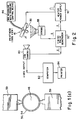
- a schematic diagram of the experimental set up used to image drops emitted from printhead 16 is shown in Figure 2.
- a CCD camera 80 connected to a computer 82 and printer 84 was used to record images of the drop at various delay times relative to the heating pulse.
- Printhead 16 was angled at thirty degrees from the horizontal so that the entire heater 50 could be viewed. Because of the reflective nature of the surface, a reflected image of the drop appeared together with the imaged drop.
- An ink reservoir and pressure control means 86 shown as one unit, was included to poise the ink meniscus at a point below the threshold of ink release.
- a fast strobe 88 was used to freeze the image of the drop in motion.
- a heater power supply 90 was used to provide a current pulse to heater 50.
- Strobe 88, camera 80, and heater power supply 90 may be synchronously triggered by a timing pulse generator 92. In this way, the time delay between strobe 88 and heater power supply 90 may be set to capture the drop at various points during its formation.
- FIG. 1(b) A 16 ⁇ m diameter nozzle, fabricated as described above and shown schematically in Figures 1(b) and 1(c), was mounted in the test setup shown schematically in Figure 2.
- the nozzle reservoir was filled with de-ionized water and pressurized to a pressure of 13.2 kPa, below the measured critical pressure of 17.0 kPa.
- the nozzle contained a hydrophobizing Teflon® layer.
- Figure 3(a) is an image of a separated drop taken 220 ⁇ s after the start of a 70 ⁇ s duration, 115 mW electrical pulse applied to heater 50.
- the application of the thermal energy to the de-ionized water in the nozzle has changed some of the physical properties of the de-ionized water, including decreasing its surface tension and viscosity.
- FIGS 3(b)-3(d) are images of separated drops taken 220 ⁇ s after the start of 100, 130, and 160 ⁇ s duration, 115 mW electrical pulses applied to heater 50. As can be seen from Figure 3, the size and hence volume of the drop is increasing with the duration of the heater pulse. In Figure 3(e), two drops are separated with the application of a 200 ⁇ s duration electrical pulse.
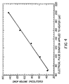
- the drop volume computed from the drop images of Figure 3 is plotted against the duration of the electrical pulse applied to heater.
- the line through the data points is a linear least squares fit.
- the drop volume is proportional to the duration of the electrical pulse applied to heater even when more than one drop is produced from a single electrical pulse. With the ability to control drop volume in such a manner, continuous toning and grayscale toning of images is possible.
Abstract


Description
- This invention relates generally to the field of digitally controlled printing devices, and in particular to liquid ink drop-on-demand printheads which integrate multiple nozzles on a single substrate and in which a poised liquid meniscus on a nozzle is expanded to a pre-determined volume and is separated for printing by thermal activation. Furthermore, the volume separated drop may be controlled to permit continuous toning and grayscale toning of images.
- Ink jet printing has become a preferred technology for the printing of color images. The term "ink jet" as used herein is intended to include all drop-on-demand or continuous ink jet propulsion systems including, but not limited to, bubble jet, thermal ink jet, piezoelectric and continuous.
- There are two types of drop-on-demand ink jet printers that dominate the market. Drop-on-demand thermal ink jet printers operate by rapidly heating a small volume of ink, causing it to vaporize and expand, thereby ejecting ink through an orifice or nozzle and causing it to land on selected areas of a recording medium. The sequenced operation of an array of such orifices moving past a recording medium writes a dot pattern of ink on the recording medium, forming text or pictorial images. The print head typically includes an ink reservoir and channels to replenish the ink to the region in which vaporization occurs. An arrangement of thermal ink jet heaters, ink channels, and nozzles is disclosed in U.S. Pat. No. 4,882,595.
- The drop-on-demand piezoelectric printers operate by using a separate piezoelectric transducer for each nozzle generating a pressure pulse to expel the drops. U.S. Pat. No. 3,946,398, which issued to Kyser et al. in 1970, discloses a drop-on-demand ink jet printer which applies a high voltage to a piezoelectric crystal, causing the crystal to bend, applying pressure on an ink reservoir and jetting drops on demand. Color rendition is accomplished by adding a few (typically three) color ink reservoirs and associated nozzles and ejection means so that dots of different colors may be overlaid on an appropriate recording medium.
- The above methods as practiced suffer from drawbacks, notable the difficulty of achieving continuous tone (grayscale) color reproduction. One method used to provide continuous tone color reproduction, namely the deposition of multiple drops with the same volume onto a single image pixel, allows only a limited number of gray levels corresponding to the number of drops deposited. The volume of ink drops has also been controlled in piezoelectric drop-on-demand printers by varying the applied energy, such as by adjusting the pulse height or pulse width of the applied electrical signal. This method tends to allow only a small volume variation and exhibits a drop velocity variation with size, making placement difficult on the recording medium.
- Drop-on-demand printing mechanisms are known in the prior art wherein the means of selecting drops to be printed is by thermal reduction of the surface tension of the selected drop producing a difference in position between selected drops and drops which are not selected but which is insufficient to cause the ink drops to overcome the ink surface tension and separate from the body of ink, and wherein an additional means is provided to cause separation of the selected drops from the body of ink. To cause separation of the drop the system requires either proximity mode, for which the recording medium must be in close proximity to the orifice in order to separate the drop from the orifice, or the use of an electric field between recording medium and orifice. A drop volume adjustment can be made, for example in proximity mode, by altering the distance between print head and recording medium which requires increased system complexity.
- It is an object of the present invention to improve upon the above invention by demonstrating a new mode of operation. This mode, which was not previously predicted, permits control of the separated drop volume for continuous toning and gray scale toning of images. A volume change of at least a factor of 3 can be obtained with only a small change in drop velocity.
- It is another object of the present invention to demonstrate a new mode of operation for a drop-on-demand printhead wherein electrothermal pulses applied to an annular heater located around the rim of a nozzle controls the expansion of a poised meniscus, the separation of the drop, and the volume of the separated drop, propelling it to the recording medium. Electrothermal pulses applied to selected nozzles heat the ink in those nozzles, altering material properties of the ink, including a reduction in the surface tension of the ink and causing it to expand past its initially poised state. Heating the ink adjacent to the heater surface to a temperature greater than its boiling point results in separation of the drop. By controlling the heating, a pre-determined drop volume may be delivered to the recording medium. This pre-determined drop volume may consist of more than one drop ejected as a result of a singly-applied electrothermal pulse.
- According to a feature of the present invention, an ink drop ejecting printhead includes a substrate having an ink drop emitting opening; a heater on the substrate surrounding the opening; and an ink supply communicating with the opening to supply ink, whose surface tension decreases inversely with its temperature, to the opening under positive pressure relative to ambient. A variable-energy electrical power supply connected to the heater, whereby application of an electrical pulse of sufficient energy to the heater will cause separation of an associated ink drop from the ink supply. A power supply control is adapted to regulate the energy of electrical pulses applied to the heater from the power supply, whereby the volumes of separated ink drops are proportional to the energy of the associated electrical pulses.
- According to another feature of the present invention, a process for ejecting ink from a printhead includes the steps of communicating an ink supply, whose surface tension decreases inversely with its temperature, with an ink-emitting opening to supply ink to the opening; applying positive pressure relative to ambient to the ink supply; adjustably applying pulses of heat to the ink at the opening of sufficient energy to cause separation of associated ink drops from the ink supply; and variably adjusting the applied heat pulse energy, whereby the volume of the separated ink drops are proportional to the energy of associated heat pulses.
- The invention, and its objects and advantages, will become more apparent in the detailed description of the preferred embodiments presented below.
- In the detailed description of the preferred embodiments of the invention presented below, reference is made to the accompanying drawings, in which:
- Figure 1(a) shows a simplified block schematic diagram of one exemplary printing apparatus in which the present invention is useful.
- Figure 1(b) shows a cross section of the nozzle tip in accordance with the present invention.
- Figure 1(c) shows a top view of the nozzle tip in accordance with the present invention.
- Figure 2 shows a simplified block schematic diagram of the experimental setup used to test the present invention.
- Figures 3(a) to 3(e) shows the variation in separated drop volume in accordance with the present invention.
- Figure 4 shows the relationship between heater pulse duration and separated drop volume in accordance with the present invention.
-
- The present description will be directed in particular to elements forming part of, or cooperating more directly with, apparatus in accordance with the present invention. It is to be understood that elements not specifically shown or described may take various forms well known to those skilled in the art.
- Figure 1(a) is a drawing of a drop-on-demand ink jet printer system utilizing the ink jet head with drop separation means. An
image source 10 may be raster image data from a scanner or computer, or outline image data in the form of a page description language, or other forms of digital image representation. This image data is converted to half-toned bitmap image data by animage processing unit 12 which also stores the image data in memory.Heater control circuits 14 read data from the image memory and apply time-varying electrical pulses to the nozzle heaters that are part of aprinthead 16. These pulses are applied at an appropriate time, and to the appropriate nozzle, so that selected drops will form spots on arecording medium 18 in the appropriate position designated by the data in the image memory. Optimal operation refers to an operating state whereby ink drops are separated and ejected from one or more pressurized nozzle orifices by the application of electrical pulses to the heater surrounding the nozzle without the need for an external drop separation means. -
Recording medium 18 is moved relative toprinthead 16 by a recordingmedium transport system 20, which is electronically controlled by a recording mediumtransport control system 22, which in turn is controlled by a micro-controller 24. A recording medium guide or platen 21 is shown directly belowprinthead 16. The recording medium transport system shown in Figure 1(a) is schematic only, and many different mechanical configurations are possible. In an alternative embodiment, a transfer roller could be used in place of the recordingmedium transport system 20 to facilitate transfer of the ink drops to recordingmedium 18. Such transfer roller technology is well known in the art. In the case of page width printheads, it is most convenient to move recordingmedium 18 past astationary printhead 16. However, in the case of scanning print systems, it is usually most convenient to moveprinthead 16 along one axis (the sub-scanning direction) and recordingmedium 18 along the orthogonal axis (the main scanning direction), in a relative raster motion. - Micro-controller 24 may also control an
ink pressure regulator 26 andheater control circuits 14. Ink is contained in anink reservoir 28 under pressure. In the quiescent state (with no ink drop ejected), the ink pressure is insufficient to overcome the ink surface tension and eject a drop. The ink pressure for optimal operation will depend mainly on the nozzle orifice diameter, surface properties (such as the degree of hydrophobicity) of abore 46 and arim 54 of the nozzle, surface tension of the ink, and power as well as temporal profile of the heater pulse. A constant ink pressure can be achieved by applying pressure toink reservoir 28 under the control ofink pressure regulator 26. Alternatively, for larger printing systems, the ink pressure can be very accurately generated and controlled by situating the top surface of the ink inreservoir 28 an appropriate distance aboveprinthead 16. This ink level can be regulated by a simple float valve (not shown). The ink is distributed to the back surface ofprinthead 16 by anink channel device 30. The ink preferably flows through slots and/or holes etched through the silicon substrate ofprinthead 16 to the front surface, where the nozzles and heaters are situated. - Figure 1(b) is a detail enlargement of a cross-sectional view of a single nozzle tip of the drop-on-demand
ink jet printhead 16 according to a preferred embodiment of the present invention. Anink delivery channel 40, along with a plurality of nozzle bores 46 are etched in asubstrate 42, which is silicon in this example. In this example,delivery channel 40 and nozzle bore 46 were formed by anisotropic wet etching of silicon, using a p+ etch stop layer to form the shape of nozzle bore 46.Ink 70 indelivery channel 40 is pressurized above atmospheric pressure, and forms ameniscus 60 which protrudes somewhat abovenozzle rim 54, at a point where the force of surface tension, which tends to hold the drop in, balances the force of the ink pressure, which tends to push the drop out. - In this example, the nozzle is of cylindrical form, with
heater 50 forming an annulus. The heater is made of polysilicon doped at a level of about thirty ohms/square, although other resistive heater material could be used.Nozzle rim 54 is formed on top ofheater 50 to provide a contact point formeniscus 60. The width of the nozzle rim in this example is from about 0.6µm to about 0.8µm.Heater 50 is separated fromsubstrate 42 by thermal and electrical insulatinglayers 56 to minimize heat loss to the substrate. - The layers in contact with the ink can be passivated with a
thin film layer 64 for protection, which can also include a layer to improve wetting of the nozzle with the ink in order to improve refill time. The printhead surface can be coated with ahydrophobizing layer 68 to prevent accidental spread of the ink across the front of the printhead. The top of nozzle rim 54 may also be coated with a protective layer which could be either hydrophobic or hydrophillic. - Figure 1(c) is an enlargement of a top view of a single nozzle of drop-on-demand
ink jet printhead 16 according to a preferred embodiment of the present invention.Nozzle rim 54 andheater annulus 50 located directly under nozzle rim 54 surrounds the periphery of nozzle bore 46. A pair of power andground connections 59 from the drive circuitry toheater annulus 50 are shown, and are fabricated to lie in the heater plane below the nozzle rim. -
Heater control circuits 14 supply electrical power to the heater for a given time duration. Optimum operation provides a sharp rise in temperature at the start of the heater pulse, a maintenance of the temperature above the boiling point of the ink in an annular volume just to the ingress of the nozzle/heater interface for part of the duration of the heater pulse, and a rapid fall in temperature at the end of the heater pulse. The heater pulse controls the expansion of a poised meniscus, the separation of the drop, and the volume of the separated drop. The power and duration of the applied heater pulse that is necessary to accomplish this depends mainly on the geometry and thermal properties (such as thermal conductivity, specific heat, and density) of the materials in and around the heater including the thermal properties of the ink as well as the surface tension and viscosity of the ink. Thermal models can be used to guide the selection of geometrical parameters and materials as well as operating ranges of the ink pressure, heater pulse power and duration. It is recognized that a certain degree of experimentation may be necessary to achieve the optimal conditions for a given geometry. - For small drop sizes, gravitational force on the ink drop is very small; approximately 10-4 of the surface tension forces, so gravity can be ignored in most cases. This allows
printhead 16 andrecording medium 18 to be oriented in any direction in relation to the local gravitational field. This is an important requirement for portable printers. - The ink jet head with drop separation means shown schematically in Figures 1(b) and 1(c) was fabricated as described above and experimentally tested. A schematic diagram of the experimental set up used to image drops emitted from
printhead 16 is shown in Figure 2. ACCD camera 80 connected to acomputer 82 andprinter 84 was used to record images of the drop at various delay times relative to the heating pulse.Printhead 16 was angled at thirty degrees from the horizontal so that theentire heater 50 could be viewed. Because of the reflective nature of the surface, a reflected image of the drop appeared together with the imaged drop. An ink reservoir and pressure control means 86, shown as one unit, was included to poise the ink meniscus at a point below the threshold of ink release. Afast strobe 88 was used to freeze the image of the drop in motion. Aheater power supply 90 was used to provide a current pulse toheater 50.Strobe 88,camera 80, andheater power supply 90 may be synchronously triggered by atiming pulse generator 92. In this way, the time delay betweenstrobe 88 andheater power supply 90 may be set to capture the drop at various points during its formation. - A 16 µm diameter nozzle, fabricated as described above and shown schematically in Figures 1(b) and 1(c), was mounted in the test setup shown schematically in Figure 2. The nozzle reservoir was filled with de-ionized water and pressurized to a pressure of 13.2 kPa, below the measured critical pressure of 17.0 kPa. The nozzle contained a hydrophobizing Teflon® layer. Figure 3(a) is an image of a separated drop taken 220 µs after the start of a 70 µs duration, 115 mW electrical pulse applied to
heater 50. The application of the thermal energy to the de-ionized water in the nozzle has changed some of the physical properties of the de-ionized water, including decreasing its surface tension and viscosity. The result is a separated drop whose volume may be controlled by the electrical pulse applied to heater. Note that the image is taken at a tilt of thirty degrees from horizontal with a reflected image of the poised meniscus also appearing. For pulse durations below 65 µs separation of the de-ionized water from the nozzle did not occur. Figures 3(b)-3(d) are images of separated drops taken 220 µs after the start of 100, 130, and 160 µs duration, 115 mW electrical pulses applied toheater 50. As can be seen from Figure 3, the size and hence volume of the drop is increasing with the duration of the heater pulse. In Figure 3(e), two drops are separated with the application of a 200 µs duration electrical pulse. - In Figure 4, the drop volume computed from the drop images of Figure 3 is plotted against the duration of the electrical pulse applied to heater. The line through the data points is a linear least squares fit. As can be seen from Figure 4, the drop volume is proportional to the duration of the electrical pulse applied to heater even when more than one drop is produced from a single electrical pulse. With the ability to control drop volume in such a manner, continuous toning and grayscale toning of images is possible.
- The invention has been described in detail with particular reference to preferred embodiments thereof, but it will be understood that variations and modifications can be effected within the spirit and scope of the invention.
Claims (9)
- An ink drop ejecting printhead comprising:a substrate having an ink drop emitting opening;a heater on the substrate surrounding the opening;an ink supply communicating with the opening to supply ink, whose surface tension decreases inversely with its temperature, to the opening under positive pressure relative to ambient;a variable-energy electrical power supply connected to the heater, whereby application of an electrical pulse of sufficient energy to the heater will cause separation of an associated ink drop from the ink supply; anda power supply control adapted to regulate the energy of electrical pulses applied to the heater from the power supply, whereby the volumes of separated ink drops are proportional to the energy of the associated electrical pulses.
- An ink ejecting printhead as set forth in Claim 1 wherein the volumes of separated ink drops are proportional to the duration of the associated electrical pulses.
- An ink ejecting printhead as set forth in Claim 1 wherein the opening and the heater are annular.
- An ink ejecting printhead as set forth in Claim 1 wherein the power supply is adapted to apply an electrical pulse of sufficient energy to heat ink adjacent to the heater to a temperature greater than its boiling point, thereby causing separation of ink from the ink supply.
- An ink ejecting printhead as set forth in Claim 1 wherein the heater is made at least in part of polysilicon doped at a level of about thirty ohms/square.
- An ink ejecting printhead as set forth in Claim 1 further comprising a thermal and electrical layer separating said substrate and the heater.
- A process for ejecting ink from a printhead, said process comprising:communicating an ink supply, whose surface tension decreases inversely with its temperature, with an ink-emitting opening to supply ink to the opening;applying positive pressure relative to ambient to the ink supply;adjustably applying pulses of heat to the ink at the opening of sufficient energy to cause separation of associated ink drops from the ink supply; andvariably adjusting the applied heat pulse energy, whereby the volume of the separated ink drops are proportional to the energy of associated heat pulses.
- A process as set forth in Claim 7 wherein the energy of the heat pulses is adjusted by adjusting the duration of the heat pulses.
- A process as set forth in Claim 7 wherein the heat pulse applying step is sufficient to heat the ink to a temperature greater than its boiling point, thereby causing separation of ink drops from the ink supply.
Applications Claiming Priority (2)
| Application Number | Priority Date | Filing Date | Title |
|---|---|---|---|
| US918474 | 1997-08-26 | ||
| US08/918,474 US6498615B1 (en) | 1997-08-26 | 1997-08-26 | Ink printing with variable drop volume separation |
Publications (2)
| Publication Number | Publication Date |
|---|---|
| EP0900656A2 true EP0900656A2 (en) | 1999-03-10 |
| EP0900656A3 EP0900656A3 (en) | 1999-07-28 |
Family
ID=25440438
Family Applications (1)
| Application Number | Title | Priority Date | Filing Date |
|---|---|---|---|
| EP98202726A Withdrawn EP0900656A3 (en) | 1997-08-26 | 1998-08-14 | Ink printing with variable drop volume separation |
Country Status (2)
| Country | Link |
|---|---|
| US (1) | US6498615B1 (en) |
| EP (1) | EP0900656A3 (en) |
Cited By (8)
| Publication number | Priority date | Publication date | Assignee | Title |
|---|---|---|---|---|
| EP1216834A3 (en) * | 2000-12-15 | 2003-06-11 | Eastman Kodak Company | Ink jet printing using drop-on-demand techniques for continuous tone printing |
| WO2007065187A1 (en) * | 2005-12-05 | 2007-06-14 | Silverbrook Research Pty Ltd | Method of modulating printhead peak power requirement using redundant nozzles |
| US7438371B2 (en) | 2005-12-05 | 2008-10-21 | Silverbrook Research Pty Ltd | Method of modulating printhead peak power requirement using redundant nozzles |
| US7441862B2 (en) | 2005-12-05 | 2008-10-28 | Silverbrook Research Pty Ltd | Method of modulating printhead peak power requirement using out-of-phase firing |
| US7455376B2 (en) | 2005-12-05 | 2008-11-25 | Silverbrook Research Pty Ltd | Printhead system for modulating printhead peak power requirement using out-of-phase firing |
| US7458659B2 (en) | 2005-12-05 | 2008-12-02 | Silverbrook Research Pty Ltd | Printer controller for modulating printhead peak power requirement using redundant nozzles |
| US7465017B2 (en) | 2005-12-05 | 2008-12-16 | Silverbrook Research Pty Ltd | Dot-at-a-time redundancy for modulating printhead peak power requirement |
| US7654636B2 (en) | 2005-12-05 | 2010-02-02 | Silverbrook Research Pty Ltd | Inkjet printhead having optimal number of printhead modules and nozzle rows for out-of-phase printing |
Families Citing this family (4)
| Publication number | Priority date | Publication date | Assignee | Title |
|---|---|---|---|---|
| DE10202991A1 (en) * | 2002-01-26 | 2003-07-31 | Roland Man Druckmasch | Easily cleanable surface for an ink-soiled component of a printing machine has a coating with hydrophilic characteristics |
| US6663214B1 (en) * | 2002-07-16 | 2003-12-16 | Industrial Technology Research Institute | Micro liquid dispenser incorporating a liquid pillar injector and method for operating |
| US7431431B2 (en) * | 2005-04-04 | 2008-10-07 | Silverbrook Research Pty Ltd | Self passivating transition metal nitride printhead heaters |
| JP2012506781A (en) * | 2008-11-10 | 2012-03-22 | シルバーブルック リサーチ ピーティワイ リミテッド | Print head with increased drive pulses to prevent heater oxide growth |
Citations (2)
| Publication number | Priority date | Publication date | Assignee | Title |
|---|---|---|---|---|
| US3946398A (en) | 1970-06-29 | 1976-03-23 | Silonics, Inc. | Method and apparatus for recording with writing fluids and drop projection means therefor |
| US4882595A (en) | 1987-10-30 | 1989-11-21 | Hewlett-Packard Company | Hydraulically tuned channel architecture |
Family Cites Families (3)
| Publication number | Priority date | Publication date | Assignee | Title |
|---|---|---|---|---|
| US5036337A (en) | 1990-06-22 | 1991-07-30 | Xerox Corporation | Thermal ink jet printhead with droplet volume control |
| AUPN232195A0 (en) | 1995-04-12 | 1995-05-04 | Eastman Kodak Company | Multiple simultaneous drop sizes in proximity lift printing |
| JP2907772B2 (en) | 1995-05-30 | 1999-06-21 | キヤノン株式会社 | Method and apparatus for measuring ink ejection amount, printing apparatus, and method for measuring ink ejection amount in printing apparatus |
-
1997
- 1997-08-26 US US08/918,474 patent/US6498615B1/en not_active Expired - Fee Related
-
1998
- 1998-08-14 EP EP98202726A patent/EP0900656A3/en not_active Withdrawn
Patent Citations (2)
| Publication number | Priority date | Publication date | Assignee | Title |
|---|---|---|---|---|
| US3946398A (en) | 1970-06-29 | 1976-03-23 | Silonics, Inc. | Method and apparatus for recording with writing fluids and drop projection means therefor |
| US4882595A (en) | 1987-10-30 | 1989-11-21 | Hewlett-Packard Company | Hydraulically tuned channel architecture |
Cited By (14)
| Publication number | Priority date | Publication date | Assignee | Title |
|---|---|---|---|---|
| EP1216834A3 (en) * | 2000-12-15 | 2003-06-11 | Eastman Kodak Company | Ink jet printing using drop-on-demand techniques for continuous tone printing |
| WO2007065187A1 (en) * | 2005-12-05 | 2007-06-14 | Silverbrook Research Pty Ltd | Method of modulating printhead peak power requirement using redundant nozzles |
| US7438371B2 (en) | 2005-12-05 | 2008-10-21 | Silverbrook Research Pty Ltd | Method of modulating printhead peak power requirement using redundant nozzles |
| US7441862B2 (en) | 2005-12-05 | 2008-10-28 | Silverbrook Research Pty Ltd | Method of modulating printhead peak power requirement using out-of-phase firing |
| US7455376B2 (en) | 2005-12-05 | 2008-11-25 | Silverbrook Research Pty Ltd | Printhead system for modulating printhead peak power requirement using out-of-phase firing |
| US7458659B2 (en) | 2005-12-05 | 2008-12-02 | Silverbrook Research Pty Ltd | Printer controller for modulating printhead peak power requirement using redundant nozzles |
| US7465017B2 (en) | 2005-12-05 | 2008-12-16 | Silverbrook Research Pty Ltd | Dot-at-a-time redundancy for modulating printhead peak power requirement |
| AU2005338846B2 (en) * | 2005-12-05 | 2009-10-01 | Memjet Technology Limited | Method of modulating printhead peak power requirement using redundant nozzles |
| US7654636B2 (en) | 2005-12-05 | 2010-02-02 | Silverbrook Research Pty Ltd | Inkjet printhead having optimal number of printhead modules and nozzle rows for out-of-phase printing |
| US7896465B2 (en) | 2005-12-05 | 2011-03-01 | Silverbrook Research Pty Ltd | Inkjet printhead with a printer controller for controlling nozzle firing sequence |
| US7918522B2 (en) | 2005-12-05 | 2011-04-05 | Silverbrook Research Pty Ltd | Printhead system for modulating printhead peak power requirement using redundant nozzles |
| US7984966B2 (en) | 2005-12-05 | 2011-07-26 | Silverbrook Research Pty Ltd | Inkjet printhead with matched number of color channels and printhead modules |
| US8066346B2 (en) | 2005-12-05 | 2011-11-29 | Silverbrook Research Pty Ltd | Printer controller for modulating printhead peak power requirement using out-of phase firing |
| US8075097B2 (en) | 2005-12-05 | 2011-12-13 | Silverbrook Research Pty Ltd | Method of modulating peak power requirement of modular printhead |
Also Published As
| Publication number | Publication date |
|---|---|
| EP0900656A3 (en) | 1999-07-28 |
| US6498615B1 (en) | 2002-12-24 |
Similar Documents
| Publication | Publication Date | Title |
|---|---|---|
| US6022099A (en) | Ink printing with drop separation | |
| EP0864423B1 (en) | Ink transfer printing apparatus with drop volume adjustment and process therefor | |
| US6509917B1 (en) | Continuous ink jet printer with binary electrostatic deflection | |
| US6883904B2 (en) | Apparatus and method for maintaining constant drop volumes in a continuous stream ink jet printer | |
| US5812159A (en) | Ink printing apparatus with improved heater | |
| EP0720534B1 (en) | High frequency drop-on-demand ink jet system | |
| US6527357B2 (en) | Assisted drop-on-demand inkjet printer | |
| US6746108B1 (en) | Method and apparatus for printing ink droplets that strike print media substantially perpendicularly | |
| EP0911168A2 (en) | Continuous ink jet printer with asymmetric heating drop deflection | |
| US6364459B1 (en) | Printing apparatus and method utilizing light-activated ink release system | |
| US6498615B1 (en) | Ink printing with variable drop volume separation | |
| JP4130715B2 (en) | Continuous ink jet printer with variable contact ink particle deflection. | |
| JPH06293140A (en) | Ink transfer printer and method | |
| US5963235A (en) | Continuous ink jet printer with micromechanical actuator drop deflection | |
| JP2002160358A (en) | Method for operation of ink jet printhead | |
| US6089692A (en) | Ink jet printing with multiple drops at pixel locations for gray scale | |
| EP1112847B1 (en) | Continuous ink jet printer with a notch deflector | |
| US20030112302A1 (en) | Continuous inkjet printer with heat actuated microvalves for controlling the direction of delivered ink | |
| EP1142718B1 (en) | Continuous ink jet printer with asymmetric drop deflection | |
| EP1216834A2 (en) | Ink jet printing using drop-on-demand techniques for continuous tone printing | |
| JP2002127403A (en) | Operating method for ink jet print head | |
| EP0911166A2 (en) | Continuous ink jet printer with electrostatic drop deflection | |
| JPH11115208A (en) | Image recorder | |
| JPH0557907A (en) | Ink jet recorder | |
| JPH07232441A (en) | Ink jet recording device and driving method thereof |
Legal Events
| Date | Code | Title | Description |
|---|---|---|---|
| PUAI | Public reference made under article 153(3) epc to a published international application that has entered the european phase |
Free format text: ORIGINAL CODE: 0009012 |
|
| AK | Designated contracting states |
Kind code of ref document: A2 Designated state(s): DE FR GB |
|
| AX | Request for extension of the european patent |
Free format text: AL;LT;LV;MK;RO;SI |
|
| PUAL | Search report despatched |
Free format text: ORIGINAL CODE: 0009013 |
|
| AK | Designated contracting states |
Kind code of ref document: A3 Designated state(s): AT BE CH CY DE DK ES FI FR GB GR IE IT LI LU MC NL PT SE |
|
| AX | Request for extension of the european patent |
Free format text: AL;LT;LV;MK;RO;SI |
|
| 17P | Request for examination filed |
Effective date: 19991211 |
|
| AKX | Designation fees paid |
Free format text: DE FR GB |
|
| 17Q | First examination report despatched |
Effective date: 20020528 |
|
| STAA | Information on the status of an ep patent application or granted ep patent |
Free format text: STATUS: THE APPLICATION IS DEEMED TO BE WITHDRAWN |
|
| 18D | Application deemed to be withdrawn |
Effective date: 20021008 |