EP0900700A2 - Electrical distribution system - Google Patents
Electrical distribution system Download PDFInfo
- Publication number
- EP0900700A2 EP0900700A2 EP98202669A EP98202669A EP0900700A2 EP 0900700 A2 EP0900700 A2 EP 0900700A2 EP 98202669 A EP98202669 A EP 98202669A EP 98202669 A EP98202669 A EP 98202669A EP 0900700 A2 EP0900700 A2 EP 0900700A2
- Authority
- EP
- European Patent Office
- Prior art keywords
- distribution board
- electrical
- power distribution
- electrical connection
- power
- Prior art date
- Legal status (The legal status is an assumption and is not a legal conclusion. Google has not performed a legal analysis and makes no representation as to the accuracy of the status listed.)
- Granted
Links
- 230000001419 dependent effect Effects 0.000 claims abstract description 5
- 238000009434 installation Methods 0.000 description 4
- 239000012777 electrically insulating material Substances 0.000 description 2
- 238000002955 isolation Methods 0.000 description 1
- 239000002184 metal Substances 0.000 description 1
- 230000004048 modification Effects 0.000 description 1
- 238000012986 modification Methods 0.000 description 1
- 239000004065 semiconductor Substances 0.000 description 1
Images
Classifications
-
- B—PERFORMING OPERATIONS; TRANSPORTING
- B60—VEHICLES IN GENERAL
- B60R—VEHICLES, VEHICLE FITTINGS, OR VEHICLE PARTS, NOT OTHERWISE PROVIDED FOR
- B60R16/00—Electric or fluid circuits specially adapted for vehicles and not otherwise provided for; Arrangement of elements of electric or fluid circuits specially adapted for vehicles and not otherwise provided for
- B60R16/02—Electric or fluid circuits specially adapted for vehicles and not otherwise provided for; Arrangement of elements of electric or fluid circuits specially adapted for vehicles and not otherwise provided for electric constitutive elements
- B60R16/023—Electric or fluid circuits specially adapted for vehicles and not otherwise provided for; Arrangement of elements of electric or fluid circuits specially adapted for vehicles and not otherwise provided for electric constitutive elements for transmission of signals between vehicle parts or subsystems
- B60R16/0238—Electrical distribution centers
-
- H—ELECTRICITY
- H05—ELECTRIC TECHNIQUES NOT OTHERWISE PROVIDED FOR
- H05K—PRINTED CIRCUITS; CASINGS OR CONSTRUCTIONAL DETAILS OF ELECTRIC APPARATUS; MANUFACTURE OF ASSEMBLAGES OF ELECTRICAL COMPONENTS
- H05K1/00—Printed circuits
- H05K1/02—Details
- H05K1/14—Structural association of two or more printed circuits
Definitions
- the present invention relates to an electrical distribution system for a motor vehicle which is used for the distribution of both electrical power and electrical signals.
- An electrical distribution system for a motor vehicle in accordance with the present invention comprises a power distribution board having an electrical connection means for connection to a power supply and an electrical connection means for connection to one or more electrical loads; a signal distribution board having an electrical connection means for receiving and transmitting electrical signals; a switch card extending between, and electrically connectable with, the power distribution board and the signal distribution board, and having electrically operable switch means mounted thereon for switching the power supply between the electrical connection means on the power distribution board; a control card extending between, and electrically connectable with, the power distribution board and the signal distribution board, and having control means mounted thereon for controlling the operation of the switch means dependent on signals received at the electrical connection means on the signal distribution board; and a casing within which the power distribution board, the signal distribution board, the switch card and the control card are mounted, the casing having openings for access to the electrical connection means.
- the present invention provides a modular arrangement for power and signal distribution which reduces wiring harness complexity, provides easier installation in a motor vehicle, and enables a reduction in the number of variants.
- the electrical distribution system 10 for use in a motor vehicle comprises a casing 12 of electrically insulating material having opposed end walls 14,16; opposed side walls 18,20; a base wall 22; and an open end 24 opposite the base wall.
- the open end 24 is closable by a cover 26 of electrically insulating material.
- the cover 26 is preferably attached to one 18 of the side walls of the casing 12 by suitable hinges 28, and can preferably make a snap fit with resilient tabs 30 on the other side wall 20 of the casing 12 to close the open end 24. Any other suitable means for attaching the cover 26 to the casing 12 may be used.
- the system 10 further comprises a signal distribution board in the form of a flexible printed circuit 32 which is secured to the base wall 22 inside the casing 12.
- the flexible printed circuit 32 has an electrical connector 34 secured to one end. When positioned inside the casing 12, the electrical connector 34 of the flexible printed circuit 32 is accessible through an opening 36 in one 14 of the end walls of the casing.
- the flexible printed circuit 32 has electrically conductive lines (not shown) formed thereon which connect with electrical contacts (not shown) mounted in the electrical connector 34.
- the electrical connector 34 is connectable with electrical lines within the motor vehicle for signals being transmitted from and received by the system 10 to electrical components in the vehicle.
- the signal distribution board may be a printed circuit board (PCB) or a flexible flat circuit (FFC) or a moulded interconnection device.
- the signal board may be connected to more than one electrical connector.
- the system 10 still further comprises a power distribution board 38 which is secured in the casing 12 near the open end 24.
- the power distribution board 38 has an electrical connector 40,42 at either end. When positioned inside the casing 12, each electrical connector 40,42 of the power distribution board 38 is accessible through an opening 44,46, respectively, in the adjacent end wall 14,16 of the casing.
- One 42 of the electrical connectors is connectable with the vehicle storage battery (not shown).
- the other electrical connector 40 is connectable with electrical loads (not shown) in the motor vehicle.
- Electrical fuse contacts 48,52 and relay contacts 50 are mounted on the power distribution board 38. These contacts 48-52 are connected to electrical contacts (not shown) in the electrical connectors 40,42 by way of electrically conductive lines (not shown) on the board 38.
- Openings 54,56,58 are formed in the board 38 adjacent the contacts 48-52 on the board.
- the flexible printed circuit 32 and the power board 38 lie in planes substantially parallel to one another and substantially parallel to the plane of the base wall 22.
- the power board 38 is preferably a printed circuit board, but may alternatively be formed from stamped metal.
- First and second switch cards 60,62 and a control card 64 extend between the power board 38 and the flexible printed circuit 32.
- the cards 60-64 are preferably substantially rigid printed circuit boards which are preferably slidably mounted in grooves 66 formed on the inner surface of the side walls 18,20 of the casing 12.
- the first and second switch cards 60,62 have one or more relays 68 mounted thereon which are electrically connected with electrically conductive lines (not shown) formed on the cards.
- Electrical fuse contacts 70 are positioned at one end 72 of the first switch card 60 and are connected with the relays 68 on the second card by way of the lines on the card. When the system 10 is assembled, the fuse contacts 70 project through the opening 54 in the power board 38 and align with the fuse contacts 48 adjacent thereto.
- Electrical fuse contacts 74 are positioned at one end 76 of the second switch card 62 and are connected with the relays 68 on the second card by way of the lines on the card. When the system 10 is assembled, the fuse contacts 74 project through the opening 58 in the power board 38 and align with the fuse contacts 52 adjacent thereto.
- the control card 64 has one or more microcomputers 78 mounted thereon which are electrically connected with electrically conductive lines (not shown) formed on the card 64.
- Electrical relay contacts 80 are positioned at one end 82 of the control card 64 and are connected with the microcomputers 78 on the card by way of the lines on the card. When the system 10 is assembled, the relay contacts 80 project through the opening 56 in the power board 38 and align with the relay contacts 50 adjacent thereto.
- each card 60-64 extends to the other end 84,86,88, respectively, of each card and form edge connectors which contact the lines on the flexible printed circuit 32.
- edge connectors A suitable arrangement for these edge connections is described in patent application no. (ref: H-200555), filed the same day as this application, and incorporated herein by reference. Any other suitable of connection may be made between the cards 60-64 and the flexible printed circuit 32.
- electrical fuses 90 electrically connect the fuse contacts 48 on the power board 38 with the fuse contacts 70 on the first switch card 60; electrical fuses 92 electrically connect the fuse contacts 52 on the power board 38 with the fuse contacts 74 on the second switch card 62; and relays 94 electrically connect the relay contacts 50 on the power board 38 with the relay contacts 80 on the control card 64.
- the fuses 90,92 and the relays 94 are preferably positioned in suitable through apertures 96 formed in a casing insert 98 which is positioned in the open end 24 of the casing 12.
- the cover 26 is pivoted and connected with the tabs 30 to close the open end 24 of the casing.
- the relays 68,94 may be replaced by any other suitable electrically controllable switching devices, such as MOSFETs.
- the fuses 90,92 may be replaced by any other suitable overload disconnection system, such as circuit breakers.
- the microcomputers 78 may be replaced by any other suitable form of logic control means or semiconductor control device.
- the electrical connectors 34,40,42 may be replaced by any other suitable electrical connection means.
- power distribution and signal distribution for a motor vehicle can be combined within a casing which can be assembled before installation on a motor vehicle.
- Power distribution from a vehicle battery to the electrical loads in a vehicle is by way of the power board 38, the fuses 90 and the relays 68,94.
- the microcomputers 78 receive and send signals by way the flexible printed circuit 32 and the fuses 92 to monitor and control the operation of the relays 68,94, and to monitor and control the operation of other electrical components in the motor vehicle.
- the present invention therefore provides a modular arrangement for combining power and signal distribution, but maintains isolation between the two distribution systems. Such an arrangement reduces the complexity of vehicle wiring harnesses and provides for easier installation in a motor vehicle.
- the present invention also lends itself for easy modification dependent on the vehicle within which the system is to be installed, and dependent on customer requirements for the vehicle, thereby reducing variants.
Landscapes
- Engineering & Computer Science (AREA)
- Microelectronics & Electronic Packaging (AREA)
- Mechanical Engineering (AREA)
- Connection Or Junction Boxes (AREA)
- Supply And Distribution Of Alternating Current (AREA)
Abstract
Description
- The present invention relates to an electrical distribution system for a motor vehicle which is used for the distribution of both electrical power and electrical signals.
- Currently, in motor vehicles, electrical power distribution and electrical signal distribution are in general isolated from one another, and/or are provided by numerous separate systems. This leads to complicated wiring harness designs, difficulties in installation in the motor vehicle, and a multitude of system casings and set-ups.
- It is an object of the present invention to simplify the electrical distribution within a motor vehicle.
- An electrical distribution system for a motor vehicle in accordance with the present invention comprises a power distribution board having an electrical connection means for connection to a power supply and an electrical connection means for connection to one or more electrical loads; a signal distribution board having an electrical connection means for receiving and transmitting electrical signals; a switch card extending between, and electrically connectable with, the power distribution board and the signal distribution board, and having electrically operable switch means mounted thereon for switching the power supply between the electrical connection means on the power distribution board; a control card extending between, and electrically connectable with, the power distribution board and the signal distribution board, and having control means mounted thereon for controlling the operation of the switch means dependent on signals received at the electrical connection means on the signal distribution board; and a casing within which the power distribution board, the signal distribution board, the switch card and the control card are mounted, the casing having openings for access to the electrical connection means.
- The present invention provides a modular arrangement for power and signal distribution which reduces wiring harness complexity, provides easier installation in a motor vehicle, and enables a reduction in the number of variants.
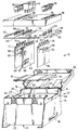
- The present invention will now be described, by way of example, with reference to the accompanying drawing in which the sole figure is an exploded view of an electrical distribution system in accordance with the present invention.
- Referring to the sole figure, the
electrical distribution system 10 for use in a motor vehicle comprises acasing 12 of electrically insulating material having opposedend walls side walls base wall 22; and anopen end 24 opposite the base wall. Theopen end 24 is closable by acover 26 of electrically insulating material. Thecover 26 is preferably attached to one 18 of the side walls of thecasing 12 bysuitable hinges 28, and can preferably make a snap fit withresilient tabs 30 on theother side wall 20 of thecasing 12 to close theopen end 24. Any other suitable means for attaching thecover 26 to thecasing 12 may be used. - The
system 10 further comprises a signal distribution board in the form of a flexible printedcircuit 32 which is secured to thebase wall 22 inside thecasing 12. The flexible printedcircuit 32 has anelectrical connector 34 secured to one end. When positioned inside thecasing 12, theelectrical connector 34 of the flexible printedcircuit 32 is accessible through anopening 36 in one 14 of the end walls of the casing. The flexible printedcircuit 32 has electrically conductive lines (not shown) formed thereon which connect with electrical contacts (not shown) mounted in theelectrical connector 34. Theelectrical connector 34 is connectable with electrical lines within the motor vehicle for signals being transmitted from and received by thesystem 10 to electrical components in the vehicle. As an alternative to a flexible printed circuit, the signal distribution board may be a printed circuit board (PCB) or a flexible flat circuit (FFC) or a moulded interconnection device. The signal board may be connected to more than one electrical connector. - The
system 10 still further comprises apower distribution board 38 which is secured in thecasing 12 near theopen end 24. Thepower distribution board 38 has anelectrical connector casing 12, eachelectrical connector power distribution board 38 is accessible through anopening adjacent end wall electrical connector 40 is connectable with electrical loads (not shown) in the motor vehicle.Electrical fuse contacts relay contacts 50 are mounted on thepower distribution board 38. These contacts 48-52 are connected to electrical contacts (not shown) in theelectrical connectors board 38.Openings board 38 adjacent the contacts 48-52 on the board. The flexible printedcircuit 32 and thepower board 38 lie in planes substantially parallel to one another and substantially parallel to the plane of thebase wall 22. Thepower board 38 is preferably a printed circuit board, but may alternatively be formed from stamped metal. - First and
second switch cards control card 64 extend between thepower board 38 and the flexible printedcircuit 32. The cards 60-64 are preferably substantially rigid printed circuit boards which are preferably slidably mounted ingrooves 66 formed on the inner surface of theside walls casing 12. The first andsecond switch cards more relays 68 mounted thereon which are electrically connected with electrically conductive lines (not shown) formed on the cards.Electrical fuse contacts 70 are positioned at oneend 72 of thefirst switch card 60 and are connected with therelays 68 on the second card by way of the lines on the card. When thesystem 10 is assembled, thefuse contacts 70 project through the opening 54 in thepower board 38 and align with thefuse contacts 48 adjacent thereto.Electrical fuse contacts 74 are positioned at oneend 76 of thesecond switch card 62 and are connected with therelays 68 on the second card by way of the lines on the card. When thesystem 10 is assembled, thefuse contacts 74 project through the opening 58 in thepower board 38 and align with thefuse contacts 52 adjacent thereto. Thecontrol card 64 has one ormore microcomputers 78 mounted thereon which are electrically connected with electrically conductive lines (not shown) formed on thecard 64.Electrical relay contacts 80 are positioned at oneend 82 of thecontrol card 64 and are connected with themicrocomputers 78 on the card by way of the lines on the card. When thesystem 10 is assembled, therelay contacts 80 project through theopening 56 in thepower board 38 and align with therelay contacts 50 adjacent thereto. The lines on each card 60-64 extend to theother end circuit 32. A suitable arrangement for these edge connections is described in patent application no. (ref: H-200555), filed the same day as this application, and incorporated herein by reference. Any other suitable of connection may be made between the cards 60-64 and the flexible printedcircuit 32. - In use, electrical fuses 90 electrically connect the
fuse contacts 48 on thepower board 38 with thefuse contacts 70 on thefirst switch card 60;electrical fuses 92 electrically connect thefuse contacts 52 on thepower board 38 with thefuse contacts 74 on thesecond switch card 62; and relays 94 electrically connect therelay contacts 50 on thepower board 38 with therelay contacts 80 on thecontrol card 64. Thefuses 90,92 and therelays 94 are preferably positioned in suitable throughapertures 96 formed in acasing insert 98 which is positioned in theopen end 24 of thecasing 12. - After assembly of the components of the
system 10 within thecasing 12, thecover 26 is pivoted and connected with thetabs 30 to close theopen end 24 of the casing. - The
relays fuses 90,92 may be replaced by any other suitable overload disconnection system, such as circuit breakers. Themicrocomputers 78 may be replaced by any other suitable form of logic control means or semiconductor control device. Theelectrical connectors - With the present invention, power distribution and signal distribution for a motor vehicle can be combined within a casing which can be assembled before installation on a motor vehicle. Power distribution from a vehicle battery to the electrical loads in a vehicle is by way of the
power board 38, the fuses 90 and therelays microcomputers 78 receive and send signals by way the flexible printedcircuit 32 and thefuses 92 to monitor and control the operation of therelays - The present invention also lends itself for easy modification dependent on the vehicle within which the system is to be installed, and dependent on customer requirements for the vehicle, thereby reducing variants.
Claims (12)
- An electrical distribution system for a motor vehicle comprising a power distribution board having an electrical connection means for connection to a power supply and an electrical connection means for connection to one or more electrical loads; a signal distribution board having an electrical connection means for receiving and transmitting electrical signals; a switch card extending between, and electrically connectable with, the power distribution board and the signal distribution board, and having electrically operable switch means mounted thereon for switching the power supply between the electrical connection means on the power distribution board; a control card extending between, and electrically connectable with, the power distribution board and the signal distribution board, and having control means mounted thereon for controlling the operation of the switch means dependent on signals received at the electrical connection means on the signal distribution board; and a casing within which the power distribution board, the signal distribution board, the switch card and the control card are mounted, the casing having openings for access to the electrical connection means.
- An electrical distribution system as claimed in Claim 1, wherein electrical fuses provide the electrical connection between the switch card and the power distribution board.
- An electrical distribution system as claimed in Claim 2, wherein the power distribution board has fuse contacts mounted thereon, and the switch card has corresponding fuse contacts which extend through an opening in the power distribution board.
- An electrical distribution system as claimed in Claim 2 or Claim 3, wherein electrical relays provide the electrical connection between the control card and the power distribution board.
- An electrical distribution system as claimed in Claim 4, wherein the power distribution board has relay contacts mounted thereon, and the control card has corresponding relay contacts which extend through an opening in the power distribution board.
- An electrical distribution system as claimed in any one of Claims 1 to 5, further comprising a second switch card extending between, and electrically connectable with, the power distribution board and the signal distribution board, and having electrically operable switch means mounted thereon for switching the power supply between the electrical connection means on the power distribution board.
- An electrical distribution system as claimed in Claim 6, wherein electrical fuses provide the electrical connection between the second switch card and the power distribution board.
- An electrical distribution system as claimed in any one of Claims 1 to 7, wherein an edge connection provides the electrical connection between signal distribution board and the switch card or cards and/or between the signal distribution board and the control card.
- An electrical distribution system as claimed in any one of Claims 1 to 8, wherein the signal distribution board is a flexible printed circuit.
- An electrical distribution system as claimed in any one of Claims 1 to 9, wherein the casing comprises a pair of end walls, a pair of side walls, a base wall, and an open end opposite the base wall, the signal distribution board being mounted on the base wall inside the casing, the power distribution board being mounted near the open end, and the openings being in the end walls.
- An electrical distribution system as claimed in Claim 10, wherein the side walls have grooves therein within which the switch card or cards and the control card make a sliding fit.
- An electrical distribution system as claimed in Claim 10 or Claim 11, wherein the open end of the casing is closable by a cover.
Applications Claiming Priority (2)
| Application Number | Priority Date | Filing Date | Title |
|---|---|---|---|
| GB9718892 | 1997-09-08 | ||
| GB9718892A GB2329075B (en) | 1997-09-08 | 1997-09-08 | Electrical distribution system |
Publications (3)
| Publication Number | Publication Date |
|---|---|
| EP0900700A2 true EP0900700A2 (en) | 1999-03-10 |
| EP0900700A3 EP0900700A3 (en) | 2002-05-22 |
| EP0900700B1 EP0900700B1 (en) | 2005-03-09 |
Family
ID=10818623
Family Applications (1)
| Application Number | Title | Priority Date | Filing Date |
|---|---|---|---|
| EP98202669A Expired - Lifetime EP0900700B1 (en) | 1997-09-08 | 1998-08-07 | Electrical distribution system |
Country Status (4)
| Country | Link |
|---|---|
| US (1) | US5973409A (en) |
| EP (1) | EP0900700B1 (en) |
| DE (1) | DE69829251T2 (en) |
| GB (1) | GB2329075B (en) |
Cited By (6)
| Publication number | Priority date | Publication date | Assignee | Title |
|---|---|---|---|---|
| EP1158643A2 (en) * | 2000-05-16 | 2001-11-28 | Autonetworks Technologies, Ltd. | Power distributor for vehicle |
| EP1178584A2 (en) * | 2000-08-02 | 2002-02-06 | Autonetworks Technologies, Ltd. | Vehicle power distributor and method of producing the same |
| EP1376803A1 (en) * | 2001-04-06 | 2004-01-02 | Yazaki Corporation | Electric junction box |
| EP0947391B1 (en) * | 1998-03-30 | 2005-12-21 | Delphi Technologies, Inc. | Electrical distribution system |
| WO2012140499A1 (en) * | 2011-04-14 | 2012-10-18 | Eaton Corporation | Circuit breaker panel |
| EP2826674A3 (en) * | 2013-07-15 | 2015-06-17 | Delphi Technologies, Inc. | Electrical center for a vehicle |
Families Citing this family (23)
| Publication number | Priority date | Publication date | Assignee | Title |
|---|---|---|---|---|
| JP2000318545A (en) * | 1999-05-12 | 2000-11-21 | Yazaki Corp | Distribution box and distribution system for vehicle |
| DE60135405D1 (en) * | 2000-03-21 | 2008-10-02 | Autonetworks Technologies Ltd | Power distributor for a motor vehicle and method of manufacture |
| JP2002058130A (en) * | 2000-08-07 | 2002-02-22 | Sumitomo Wiring Syst Ltd | Electric junction box |
| JP2002142333A (en) * | 2000-11-02 | 2002-05-17 | Auto Network Gijutsu Kenkyusho:Kk | Power distributor for vehicle |
| US7020790B2 (en) * | 2001-02-08 | 2006-03-28 | Honeywell International Inc. | Electric load management center including gateway module and multiple load management modules for distributing power to multiple loads |
| US7007179B2 (en) * | 2001-02-08 | 2006-02-28 | Honeywell International Inc. | Electric load management center |
| US7342325B2 (en) * | 2001-11-05 | 2008-03-11 | Michael Rhodes | Universal fleet electrical system |
| US6600236B2 (en) | 2001-11-05 | 2003-07-29 | Michael Rhodes | Universal fleet electrical system |
| US20040048142A1 (en) * | 2002-06-04 | 2004-03-11 | Marusak Brian T. | Power management and distribution assembly mountable to a battery |
| US20070038642A1 (en) * | 2004-09-15 | 2007-02-15 | Scott Durgin | Method for providing extensible software components within a distributed synchronization system |
| US7554796B2 (en) * | 2006-01-20 | 2009-06-30 | Adc Telecommunications, Inc. | Modular power distribution system and methods |
| US7708097B1 (en) | 2006-06-02 | 2010-05-04 | Polaris Industries Inc. | Combination mounting feature and cover for electrical components |
| US8248984B2 (en) * | 2007-06-20 | 2012-08-21 | I Squared Llc | System and method for interfacing devices |
| EP2461440B1 (en) * | 2010-12-03 | 2018-05-02 | ABB Schweiz AG | Plug-in system |
| JP5088427B2 (en) * | 2011-03-02 | 2012-12-05 | 第一精工株式会社 | Electrical connector and electrical connector assembly |
| US20120268864A1 (en) * | 2011-04-21 | 2012-10-25 | Delphi Technologies, Inc. | Apparatus having plurality of openings to access removable electronic devices some of which have electrical connections using no circuit board trace |
| US8994228B2 (en) * | 2011-11-03 | 2015-03-31 | Ford Global Technologies, Llc | Proximity switch having wrong touch feedback |
| CN103692982B (en) * | 2013-12-13 | 2015-10-07 | 东风柳州汽车有限公司 | Automotive electrical appliance load control device and control method thereof |
| DE102015121834A1 (en) * | 2015-12-15 | 2017-06-22 | Lisa Dräxlmaier GmbH | Power supply device for a vehicle |
| ES2710426T3 (en) * | 2015-12-15 | 2019-04-25 | Draexlmaier Lisa Gmbh | Distributor of electric power for a vehicle |
| DE102015121835A1 (en) * | 2015-12-15 | 2017-06-22 | Lisa Dräxlmaier GmbH | Electric power distributor for a vehicle |
| US10069226B2 (en) | 2017-01-31 | 2018-09-04 | Murrelektronik, Inc. | Power distribution module |
| WO2021258336A1 (en) * | 2020-06-24 | 2021-12-30 | 华为技术有限公司 | Vehicle control device, vehicle integration unit, and vehicle |
Family Cites Families (12)
| Publication number | Priority date | Publication date | Assignee | Title |
|---|---|---|---|---|
| DE8034130U1 (en) * | 1981-05-27 | Kabelwerke Reinshagen Gmbh, 5600 Wuppertal | Central electrics | |
| DE2409660A1 (en) * | 1974-02-28 | 1975-09-25 | Siemens Ag | Electrical control system for motor vehicle switch gear - has housing with printed circuit and plug in control unitss and fuses |
| DE3439410A1 (en) * | 1984-10-27 | 1986-04-30 | Stribel GmbH, 7443 Frickenhausen | DEVICE FOR A MOTOR VEHICLE |
| US5023752A (en) * | 1989-10-31 | 1991-06-11 | General Motors Corporation | Electrical power distribution center |
| US5030108A (en) * | 1990-06-29 | 1991-07-09 | Amp Incorporated | Card edge bus bar assembly for power distribution system |
| US5179503A (en) * | 1991-04-19 | 1993-01-12 | United Technologies Automotive, Inc. | Modular automobile power distribution box |
| FR2690601B1 (en) * | 1992-04-22 | 2002-02-01 | Valeo Electronique | Service board for controlling and / or supplying electrical components to vehicles. |
| JP3107113B2 (en) * | 1992-06-09 | 2000-11-06 | 矢崎総業株式会社 | Electrical junction box |
| DE4227182C1 (en) * | 1992-08-17 | 1993-12-02 | Reinshagen Kabelwerk Gmbh | Central unit |
| DE4422434C2 (en) * | 1994-06-28 | 1999-06-24 | Kostal Leopold Gmbh & Co Kg | Central electrics |
| JPH0872633A (en) * | 1994-09-01 | 1996-03-19 | Sumitomo Wiring Syst Ltd | Current distributing device of automobile |
| US5869907A (en) * | 1996-01-23 | 1999-02-09 | Marler; Rick A. | Modular wiring harness for a vehicle |
-
1997
- 1997-09-08 GB GB9718892A patent/GB2329075B/en not_active Expired - Fee Related
-
1998
- 1998-03-10 US US09/037,820 patent/US5973409A/en not_active Expired - Lifetime
- 1998-08-07 EP EP98202669A patent/EP0900700B1/en not_active Expired - Lifetime
- 1998-08-07 DE DE69829251T patent/DE69829251T2/en not_active Expired - Lifetime
Non-Patent Citations (1)
| Title |
|---|
| None |
Cited By (12)
| Publication number | Priority date | Publication date | Assignee | Title |
|---|---|---|---|---|
| EP0947391B1 (en) * | 1998-03-30 | 2005-12-21 | Delphi Technologies, Inc. | Electrical distribution system |
| EP1158643A2 (en) * | 2000-05-16 | 2001-11-28 | Autonetworks Technologies, Ltd. | Power distributor for vehicle |
| EP1158643A3 (en) * | 2000-05-16 | 2005-10-05 | Autonetworks Technologies, Ltd. | Power distributor for vehicle |
| EP1178584A2 (en) * | 2000-08-02 | 2002-02-06 | Autonetworks Technologies, Ltd. | Vehicle power distributor and method of producing the same |
| EP1178584A3 (en) * | 2000-08-02 | 2005-01-05 | Autonetworks Technologies, Ltd. | Vehicle power distributor and method of producing the same |
| EP1376803A1 (en) * | 2001-04-06 | 2004-01-02 | Yazaki Corporation | Electric junction box |
| EP1376803A4 (en) * | 2001-04-06 | 2005-06-15 | Yazaki Corp | Electric junction box |
| WO2012140499A1 (en) * | 2011-04-14 | 2012-10-18 | Eaton Corporation | Circuit breaker panel |
| US8488302B2 (en) | 2011-04-14 | 2013-07-16 | Eaton Corporation | Circuit breaker panel |
| CN103477517A (en) * | 2011-04-14 | 2013-12-25 | 伊顿公司 | Circuit breaker panel |
| CN103477517B (en) * | 2011-04-14 | 2016-10-19 | 雷比诺有限责任公司 | Circuit breaker panel |
| EP2826674A3 (en) * | 2013-07-15 | 2015-06-17 | Delphi Technologies, Inc. | Electrical center for a vehicle |
Also Published As
| Publication number | Publication date |
|---|---|
| GB2329075A (en) | 1999-03-10 |
| DE69829251D1 (en) | 2005-04-14 |
| EP0900700B1 (en) | 2005-03-09 |
| DE69829251T2 (en) | 2005-08-04 |
| EP0900700A3 (en) | 2002-05-22 |
| GB9718892D0 (en) | 1997-11-12 |
| GB2329075B (en) | 2002-01-23 |
| US5973409A (en) | 1999-10-26 |
Similar Documents
| Publication | Publication Date | Title |
|---|---|---|
| EP0900700B1 (en) | Electrical distribution system | |
| US6150734A (en) | Electrical distribution system | |
| US6062914A (en) | Circuit breaker plug in bracket and auxiliary/alarm switch connector for use therewith | |
| CA2240905C (en) | Power distribution center | |
| US8207454B2 (en) | Electrical junction box | |
| US5882213A (en) | Battery mounted junction box | |
| US5668698A (en) | Smart connector for an electrical device | |
| US5823798A (en) | Electric center for motor vehicles | |
| JP2002343331A (en) | Battery | |
| US5771151A (en) | Central electrical assembly | |
| US11220229B2 (en) | Modular power distribution device | |
| EP0901211B1 (en) | Electrical distribution system | |
| US6994562B2 (en) | Apparatus for multiplex communication | |
| US4542372A (en) | Data distribution apparatus | |
| EP0947391B1 (en) | Electrical distribution system | |
| US6575782B2 (en) | Modular central electrical unit for motor vehicles | |
| JP2752015B2 (en) | Mounting structure of electrical junction box and relay unit | |
| US7411476B2 (en) | Combination of a switching device and a printed board | |
| EP0701925B1 (en) | A branch connection device for an automotive vehicle | |
| KR100370996B1 (en) | Electric connection box | |
| EP0984516B1 (en) | Electrical connector for a PCB | |
| KR100507001B1 (en) | Junction block for a vehicle | |
| US7270547B2 (en) | Adapter for car radios | |
| GB2329077A (en) | Modular electric wiring system | |
| JP2752016B2 (en) | Mounting structure of electrical junction box and relay unit |
Legal Events
| Date | Code | Title | Description |
|---|---|---|---|
| PUAI | Public reference made under article 153(3) epc to a published international application that has entered the european phase |
Free format text: ORIGINAL CODE: 0009012 |
|
| AK | Designated contracting states |
Kind code of ref document: A2 Designated state(s): AT BE CH CY DE DK ES FI FR GB GR IE IT LI LU MC NL PT SE |
|
| AX | Request for extension of the european patent |
Free format text: AL;LT;LV;MK;RO;SI |
|
| PUAL | Search report despatched |
Free format text: ORIGINAL CODE: 0009013 |
|
| AX | Request for extension of the european patent |
Free format text: AL;LT;LV;MK;RO;SI |
|
| 17P | Request for examination filed |
Effective date: 20021122 |
|
| AKX | Designation fees paid |
Designated state(s): DE FR IT |
|
| 17Q | First examination report despatched |
Effective date: 20030904 |
|
| RAP1 | Party data changed (applicant data changed or rights of an application transferred) |
Owner name: DELPHI TECHNOLOGIES, INC. |
|
| GRAP | Despatch of communication of intention to grant a patent |
Free format text: ORIGINAL CODE: EPIDOSNIGR1 |
|
| GRAS | Grant fee paid |
Free format text: ORIGINAL CODE: EPIDOSNIGR3 |
|
| GRAA | (expected) grant |
Free format text: ORIGINAL CODE: 0009210 |
|
| AK | Designated contracting states |
Kind code of ref document: B1 Designated state(s): DE FR IT |
|
| REG | Reference to a national code |
Ref country code: IE Ref legal event code: FG4D |
|
| REF | Corresponds to: |
Ref document number: 69829251 Country of ref document: DE Date of ref document: 20050414 Kind code of ref document: P |
|
| ET | Fr: translation filed | ||
| PLBE | No opposition filed within time limit |
Free format text: ORIGINAL CODE: 0009261 |
|
| STAA | Information on the status of an ep patent application or granted ep patent |
Free format text: STATUS: NO OPPOSITION FILED WITHIN TIME LIMIT |
|
| 26N | No opposition filed |
Effective date: 20051212 |
|
| PGFP | Annual fee paid to national office [announced via postgrant information from national office to epo] |
Ref country code: FR Payment date: 20090814 Year of fee payment: 12 |
|
| PGFP | Annual fee paid to national office [announced via postgrant information from national office to epo] |
Ref country code: DE Payment date: 20090730 Year of fee payment: 12 |
|
| PGFP | Annual fee paid to national office [announced via postgrant information from national office to epo] |
Ref country code: IT Payment date: 20090814 Year of fee payment: 12 |
|
| REG | Reference to a national code |
Ref country code: FR Ref legal event code: ST Effective date: 20110502 |
|
| PG25 | Lapsed in a contracting state [announced via postgrant information from national office to epo] |
Ref country code: IT Free format text: LAPSE BECAUSE OF NON-PAYMENT OF DUE FEES Effective date: 20100807 |
|
| REG | Reference to a national code |
Ref country code: DE Ref legal event code: R119 Ref document number: 69829251 Country of ref document: DE Effective date: 20110301 |
|
| PG25 | Lapsed in a contracting state [announced via postgrant information from national office to epo] |
Ref country code: FR Free format text: LAPSE BECAUSE OF NON-PAYMENT OF DUE FEES Effective date: 20100831 Ref country code: DE Free format text: LAPSE BECAUSE OF NON-PAYMENT OF DUE FEES Effective date: 20110301 |