EP0900701A1 - Passenger protection device for a vehicle - Google Patents
Passenger protection device for a vehicle Download PDFInfo
- Publication number
- EP0900701A1 EP0900701A1 EP98116337A EP98116337A EP0900701A1 EP 0900701 A1 EP0900701 A1 EP 0900701A1 EP 98116337 A EP98116337 A EP 98116337A EP 98116337 A EP98116337 A EP 98116337A EP 0900701 A1 EP0900701 A1 EP 0900701A1
- Authority
- EP
- European Patent Office
- Prior art keywords
- gas
- gas chamber
- chamber
- thoracic
- occupant
- Prior art date
- Legal status (The legal status is an assumption and is not a legal conclusion. Google has not performed a legal analysis and makes no representation as to the accuracy of the status listed.)
- Granted
Links
Images


Classifications
-
- B—PERFORMING OPERATIONS; TRANSPORTING
- B60—VEHICLES IN GENERAL
- B60R—VEHICLES, VEHICLE FITTINGS, OR VEHICLE PARTS, NOT OTHERWISE PROVIDED FOR
- B60R21/00—Arrangements or fittings on vehicles for protecting or preventing injuries to occupants or pedestrians in case of accidents or other traffic risks
- B60R21/02—Occupant safety arrangements or fittings, e.g. crash pads
- B60R21/16—Inflatable occupant restraints or confinements designed to inflate upon impact or impending impact, e.g. air bags
- B60R21/23—Inflatable members
- B60R21/231—Inflatable members characterised by their shape, construction or spatial configuration
- B60R21/233—Inflatable members characterised by their shape, construction or spatial configuration comprising a plurality of individual compartments; comprising two or more bag-like members, one within the other
- B60R2021/23324—Inner walls crating separate compartments, e.g. communicating with vents
- B60R2021/23332—Inner walls crating separate compartments, e.g. communicating with vents using independent bags, one within the other
Definitions
- the invention relates to an occupant protection device for a motor vehicle with at least an inflatable airbag according to the preamble of claim 1.
- an inflatable airbag which, when activated, at least of an associated gas generator from an outlet opening in the area in front of a Occupants exits inside the motor vehicle.
- This airbag contains two chambers, whereby a lower thoracic gas chamber is inflatable by the gas generator.
- a head protection gas chamber Above the Chest protection gas chamber with a common partition is a head protection gas chamber arranged, gas flow openings are provided in the intermediate wall, through which the head protection gas chamber can be inflated via the thorax protection gas chamber.
- a gas jet is immediately on the occupant directed so that the airbag immediately after it emerges from the outlet opening undesirably violent aggressiveness aimed at the occupant shoots before the chest gas chamber unfolded and then also through the gas flow openings Head protection gas chamber is inflated.
- the total inflated airbag has one Balloon-like shape, so that a bulge-like bulge is also present in the neck area. It cannot be ruled out that the airbag, in particular on its Occupant-directed connection point between the chest gas chamber and the Headguard gas chamber moves under the occupant's chin and then the occupant's head against the direction of impact with heavy strain on the cervical spine backwards is accelerated.
- a gas diffuser after a gas generator (WO 96 25 309) with which the jet direction of the gas can be influenced and one directed towards an occupant Gas jet can be divided into different directions.
- a gas generator WO 96 25 309
- Such a diffuser is an additional one Component that requires installation space and that increases the vehicle weight. For an additional function such a diffuser should not be used regularly.
- the object of the invention is to provide a generic occupant protection device To improve that the aggressiveness of a simple structure and high protective function Airbags is reduced.
- the thorax protective gas chamber is a smaller inflatable gas pre-chamber upstream, which is connected to and directly from the gas generator is inflatable.
- the gas antechamber is connected to the thoracic protective gas chamber by means of gas flow openings connected, so that the thoracic gas chamber indirectly through the gas generator is inflatable via the gas antechamber.
- the gas antechamber is preferably in the lower one Area on the thoracic protective gas chamber without a supporting function for an occupant, so that a gas jet directed directly into the gas antechamber does not come into contact with an occupant caused.
- the at least two gas flow openings are in one lateral upper area of the gas antechamber to the thoracic protective gas chamber. This represents one favorable arrangement of the gas flow openings to avoid axially on the occupant directed gas jet.
- the outlet opening for the airbag is through an aperture or Cover opening closed when airbag is not activated.
- the first volume enlargement of the gas antechamber in one Additional function for removing the cover or cover can be used.
- This function is particularly suitable for an outlet opening in a control panel with a continuous, seamless panel cover and a tear-open cover. Doing so behind the tear-open cover a swiveling downward on the back of the tear-open cover Tear lever held adjacent, which when the gas generator is activated is swung down through the inflatable prechamber and thereby the Tear open.
- the tear-open cover for example, as an angle lever achieves that after airbag activation and removal of the outlet cover no fixed lid parts are thrown uncontrollably towards an occupant, since the tear lever is kept in the pivot bearing and only relatively soft and flexible Protect parts of the control panel cover from the surface of the control panel. All in all this creates the possibility of injury at the outlet opening or through cover parts decreased.
- the airbag in particular the head protection gas chamber in the Neck area of an occupant does not have a neck bulge, which is associated with the risk of cervical vertebral injuries could get under the chin of an impacting occupant. Also through this design measure of the airbag reduces its aggressiveness with one targeted influence on the kinematics of the occupant.
- a second or two-stage gas generator which is connected to the thoracic protective gas chamber or a further thoracic protective gas chamber for a second, delayed inflation process.
- a second inflation process can provide improved support in the event of a very severe impact and / or a very heavy occupant and / or a Out of position "position may be advantageous.
- These boundary conditions for triggering a second inflation process can be detected using devices known per se, such as impact sensors and / or occupant detection devices.
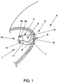
- FIG. 1 schematically shows an occupant protection arrangement 1 for a motor vehicle.
- This occupant protection device 1 has an airbag arrangement 3 with a multi-chamber Airbag 2, which can be activated by means of a first and second gas generator 33, 34 is.
- the airbag 2 occurs in a switch panel 5 Formable exit opening in the area in front of an occupant into the interior 4 of the motor vehicle.
- the control panel 5 is made of a continuous, seamless panel cover 6 with a Tear-off cover 7 constructed.
- an arcuate angle lever 9 which can be pivoted downwards arranged as a tear lever.
- an approximately horizontal first angle leg 11 is pivotable at the end stored while a second, approximately vertical angle leg 12 on the back 8 of Tear-off cover 7 abuts.
- a second, approximately vertical angle leg 12 on the back 8 of Tear-off cover 7 abuts.
- vertical Angle leg 12 is a weakening of material in the control panel cover 6 as a predetermined tear-open edge 13 of the tear-open cover 7 is formed.
- the first stage of airbag activation first a gas pre-chamber 14 by means of the first gas generator 33 inflated.
- the tear-open cover 7 angled lever 9 down from its rest position 10 moves, as indicated by arrow 15.
- the angle lever 9 exercises one of these great force on the tear-open cover 7, that the panel cover 6 in the area of Solonner employedkante 13 tears and the tear-open cover 7 is also moved down.
- the gas pre-chamber 14 does not perform a support function for the occupant 16.
- the gas antechamber is 14 upstream of a thorax protective gas chamber 19 of the airbag 2 and with it connected via gas flow openings 17, 18.
- the two gas flow openings 17, 18 are each in a lateral, upper area of the gas pre-chamber 14 for Thoracic gas chamber 19 arranged.
- the thoracic protective gas chamber 19 is thus indirect inflatable through the gas pre-chamber 14 by the first gas generator 33.
- the chest protection gas chamber 19 as is shown schematically in FIG. 4, in the second stage of airbag activation for chest protection of occupant 16 without one inflated directly onto this acting gas jet.
- the thoracic protective gas chamber 19 is, as can be seen from FIG. 2, with a head protecting gas chamber 23 connected, which can be inflated via two gas flow openings 20, 21 is. These gas flow openings 20, 21 are each in a lateral, upper area the chest protection gas chamber 19 to the head protection gas chamber 23.
- the Headrest gas chamber 23 is also indirectly inflated by the first gas generator 33.
- the head protection gas chamber 23, as shown in the schematic 5 can be seen in the third stage of airbag activation for one Head protection of the occupant 16 also without a gas jet acting directly on it inflated over the chest gas chamber 19.
- the head protection gas chamber 23 has a U-bead shape on, whose U-leg ends 24, 25 point downward and in the area of the lateral Gas flow openings 20, 21 connected to the thoracic protective gas chamber 19 are.
- the head protection gas chamber 23 in the neck impact area 26 of the occupant 16 no neck bulge.
- the head protection gas chamber is in the area of the U base 29 23 beads 27, 28 of the U-legs 30, 31 pulled upwards relative to this U-base 29 and thickened and thus serve as slip protection in the event of an oblique impact.
- a second, preferably smaller, thorax protective gas chamber 32 which is contained in the first thoracic protective gas chamber 19, is inflated at a different time than the first inflating process via the second gas generator 34 in a second inflation process.
- this second thoracic protective gas chamber 32 reinforces the supporting function of the first thoracic protective gas chamber 19, e.g. B. in a very severe impact and / or in a very heavy occupant 16 and / or one Out of position "position of the occupant 16.
- the second inflation process is triggered, for example, with the aid of impact sensors and / or occupant detection devices.
Landscapes
- Engineering & Computer Science (AREA)
- Mechanical Engineering (AREA)
- Air Bags (AREA)
Abstract
Description
Die Erfindung betrifft eine Insassenschutzorrichtung für ein Kraftfahrzeug mit mindestens
einem aufblasbaren Airbag nach dem Oberbegriff des Anspruchs 1.The invention relates to an occupant protection device for a motor vehicle with at least
an inflatable airbag according to the preamble of
Bei einer gattungsgemäßen Insassenschutzvorrichtung für ein Kraftfahrzeug (EP 0 593 172 A1) ist ein aufblasbarer Airbag verwendet, der bei einer Aktivierung wenigstens eines zugehörigen Gasgenerators aus einer Austrittsöffnung im Bereich vor einem Insassen ins Innere des Kraftfahrzeugs austritt. Dieser Airbag enthält zwei Kammern, wobei eine untere Thoraxschutz-Gaskammer durch den Gasgenerator aufblasbar ist. Über der Thoraxschutz-Gaskammer ist mit einer gemeinsamen Zwischenwand eine Kopfschutz-Gaskammer angeordnet, wobei in der Zwischenwand Gasdurchströmöffnungen angebracht sind, durch die über die Thoraxschutz-Gaskammer die Kopfschutz-Gaskammer aufblasbar ist.In a generic occupant protection device for a motor vehicle (EP 0 593 172 A1) an inflatable airbag is used which, when activated, at least of an associated gas generator from an outlet opening in the area in front of a Occupants exits inside the motor vehicle. This airbag contains two chambers, whereby a lower thoracic gas chamber is inflatable by the gas generator. Above the Chest protection gas chamber with a common partition is a head protection gas chamber arranged, gas flow openings are provided in the intermediate wall, through which the head protection gas chamber can be inflated via the thorax protection gas chamber.
Nach der Aktivierung des Gasgenerators ist ein Gasstrahl unmittelbar auf den Insassen gerichtet, so daß der Airbag unmittelbar nach seinem Austreten aus der Austrittsöffnung mit unerwünscht heftiger Aggressivität gerichtet auf den Insassen schießt, bevor sich die Thoraxschutz-Gaskammer entfaltet und dann über die Gasdurchströmöffnungen auch die Kopfschutz-Gaskammer aufgeblasen wird. Der insgesamt aufgeblasene Airbag hat eine ballonartige Form, so daß auch im Halsauftreffbereich eine wulstartige Ausbauchung vorliegt. Dadurch ist nicht auszuschließen, daß sich der Airbag insbesondere an seiner auf den Insassen zugerichteten Verbindungsstelle zwischen der Thoraxschutz-Gaskammer und der Kopfschutz-Gaskammer unter das Kinn des Insassen bewegt und dann der Kopf des Insassen entgegen der Aufprallrichtung mit starker Beanspruchung der Halswirbelsäule rückwärts beschleunigt wird.After activating the gas generator, a gas jet is immediately on the occupant directed so that the airbag immediately after it emerges from the outlet opening undesirably violent aggressiveness aimed at the occupant shoots before the chest gas chamber unfolded and then also through the gas flow openings Head protection gas chamber is inflated. The total inflated airbag has one Balloon-like shape, so that a bulge-like bulge is also present in the neck area. It cannot be ruled out that the airbag, in particular on its Occupant-directed connection point between the chest gas chamber and the Headguard gas chamber moves under the occupant's chin and then the occupant's head against the direction of impact with heavy strain on the cervical spine backwards is accelerated.
Bei einer weiter bekannten Insassenschutzvorrichtung für ein Kraftfahrzeug mit einem im Bereich vor einem Insassen aufblasbaren Airbag (DE 297 00 804 U1) ist dieser im aufgeblasenen Zustand unsymmetrisch geformt, dergestalt, daß im Kopfaufprallbereich ein größeres Volumen als im Thoraxaufprallbereich vorliegt. Allgemein ist auf die Möglichkeit hingewiesen, einen solchen Airbag in mehrere aufzublasende Kammern zu unterteilen, wozu jedoch keine konkreten Angaben gemacht sind. Auch hier ist ein initialer Gasstrahl aus dem Gasgenerator mit unerwünschter Aggressivität auf den Insassen gerichtet.In a further known occupant protection device for a motor vehicle with a The area in front of an inflatable airbag (DE 297 00 804 U1) is inflated Condition asymmetrically shaped, such that a larger one in the head impact area Volume than in the chest impact area. In general, the possibility is pointed out to divide such an airbag into several inflatable chambers, for what however, no specific information is given. Here too is an initial gas jet from the Gas generator aimed at the occupant with undesirable aggressiveness.
Weiter ist eine Insassenschutzvorrichtung für ein Kraftfahrzeug gegen einen Seitenaufprall bekannt (DE 195 38 657 A1), bei der aus einer Austrittsöffnung einer Rückenlehne ein Airbag mit einer Thoraxschutz-Gaskammer und einer daran anschließenden Kopfschutz-Gaskammer austritt. Hier ist der Gasstrahl aus dem zugeordneten Gasgenerator in Fahrzeuglängsrichtung gerichtet, so daß bei einem solchen Seitenairbag das Problem einer hohen Aggressivität durch einen auf den Insassen gerichteten Gasstrahl nicht auftritt.Next is an occupant protection device for a motor vehicle against a side impact known (DE 195 38 657 A1), in which from a discharge opening of a backrest Airbag with a chest protection gas chamber and an adjoining head protection gas chamber exit. Here is the gas jet from the assigned gas generator in the vehicle's longitudinal direction directed so that with such a side airbag the problem of a high Aggressiveness caused by a gas jet directed at the occupant does not occur.
Es ist weiter bekannt, einen Gasdiffusor einem Gasgenerator nachzuordnen (WO 96 25 309) mit dem die Strahlrichtung des Gases beeinflußbar ist und ein auf einen Insassen gerichteter Gasstrahl in unterschiedliche Richtungen aufteilbar ist. Ein solcher Diffusor ist ein zusätzliches Bauteil, das einen Einbauraum erfordert und das das Fahrzeuggewicht erhöht. Für eine zusätzliche Funktion ist ein solcher Diffusor regelmäßig nicht zu verwenden.It is also known to arrange a gas diffuser after a gas generator (WO 96 25 309) with which the jet direction of the gas can be influenced and one directed towards an occupant Gas jet can be divided into different directions. Such a diffuser is an additional one Component that requires installation space and that increases the vehicle weight. For an additional function such a diffuser should not be used regularly.
Aufgabe der Erfindung ist es, eine gattungsgemäße Insassenschutzvorrichtung dahingehend zu verbessern, daß bei einfachem Aufbau und hoher Schutzfunktion die Aggressivität eines Airbags reduziert wird.The object of the invention is to provide a generic occupant protection device To improve that the aggressiveness of a simple structure and high protective function Airbags is reduced.
Diese Aufgabe wird mit den Merkmalen des Anspruchs 1 gelöst.This object is achieved with the features of
Gemäß Anspruch 1 ist der Thoraxschutz-Gaskammer eine kleinere aufblasbare Gasvorkammer
vorgeordnet, die mit dem Gasgenerator in Verbindung steht und von diesem unmittelbar
aufblasbar ist. Die Gasvorkammer ist mittels Gasdurchströmöffnungen mit der Thoraxschutz-Gaskammer
verbunden, so daß die Thoraxschutz-Gaskammer mittelbar durch
den Gasgenerator über die Gasvorkammer aufblasbar ist. According to
Dadurch wird erreicht, daß der Gasstrahl aus dem Gasgenerator nicht direkt auf den Insassen gerichtet ist sondern über die umlenkenden Gasdurchströmöffnungen von der Gasvorkammer in die Thoraxschutz-Gaskammer gelangt. Dadurch ist die Aggressivität des Airbags durch ein unerwünscht heftiges Auftreffen auf einen Insassen verringert. Ein zusätzliches Diffusorteil kann entbehrlich sein.This ensures that the gas jet from the gas generator is not directly on the occupant is directed but via the deflecting gas flow openings from the gas pre-chamber enters the thoracic protective gas chamber. This makes the airbag aggressive reduced by an undesirably violent impact on an occupant. An additional Diffuser part can be unnecessary.
Bevorzugt liegt dabei im aufgeblasenen Zustand des Airbags die Gasvorkammer im unteren Bereich an der Thoraxschutz-Gaskammer ohne Abstützfunktion für einen Insassen, so daß ein in die Gasvorkammer unmittelbar gerichteter Gasstrahl keine Berührung mit einem Insassen verursacht. Die wenigstens zwei Gasdurchströmöffnungen liegen dabei in einem seitlichen oberen Bereich der Gasvorkammer zur Thoraxschutz-Gaskammer. Dies stellt eine günstige Anordnung der Gasdurchströmöffnungen zur Vermeidung eines axial auf den Insassen gerichteten Gasstrahls dar.In the inflated state of the airbag, the gas antechamber is preferably in the lower one Area on the thoracic protective gas chamber without a supporting function for an occupant, so that a gas jet directed directly into the gas antechamber does not come into contact with an occupant caused. The at least two gas flow openings are in one lateral upper area of the gas antechamber to the thoracic protective gas chamber. This represents one favorable arrangement of the gas flow openings to avoid axially on the occupant directed gas jet.
In an sich bekannter Weise ist die Austrittsöffnung für den Airbag durch eine Blende oder Abdecköffnung bei nicht aktiviertem Airbag verschlossen. Vorteilhaft kann hier bei einer Aktivierung des Gasgenerators die erste Volumenvergrößerung der Gasvorkammer in einer Zusatzfunktion zur Entfernung der Blende oder Abdeckung verwendet werden.In a manner known per se, the outlet opening for the airbag is through an aperture or Cover opening closed when airbag is not activated. Can be advantageous here with a Activation of the gas generator the first volume enlargement of the gas antechamber in one Additional function for removing the cover or cover can be used.
Besonders geeignet ist diese Funktion bei einer Austrittsöffnung in einer Schalttafel mit einer durchgehenden, fugenlosen Schalttafelabdeckung und einem Aufreißdeckel. Dabei wird hinter dem Aufreißdeckel ein nach unten schwenkbarer, an der Rückseite des Aufreißdeckels anliegend gehaltener Aufreißhebel angeordnet, der bei einer Aktivierung des Gasgenerators durch die aufblasbare Vorkammer nach unten geschwenkt wird und dabei den Aufreißdeckel aufreißt.This function is particularly suitable for an outlet opening in a control panel with a continuous, seamless panel cover and a tear-open cover. Doing so behind the tear-open cover a swiveling downward on the back of the tear-open cover Tear lever held adjacent, which when the gas generator is activated is swung down through the inflatable prechamber and thereby the Tear open.
Bei einer geeigneten Formgebung des Aufreißdeckels beispielsweise als Winkelhebel wird erreicht, daß nach einer Airbagaktivierung und Entfernung der Austrittsöffnungsabdeckung keine festen Deckelteile unkontrolliert in Richtung auf einen Insassen geschleudert werden, da der Aufreißhebel weiter im Schwenklager gehalten ist und nur relativ weiche und nachgiebige Teile der Schaltdafelabdeckung aus der Schalttafeloberfläche abstehen. Insgesamt wird dadurch die Möglichkeit einer Verletzung an der Austrittsöffnung oder durch Deckelteile verringert.With a suitable shape of the tear-open cover, for example, as an angle lever achieves that after airbag activation and removal of the outlet cover no fixed lid parts are thrown uncontrollably towards an occupant, since the tear lever is kept in the pivot bearing and only relatively soft and flexible Protect parts of the control panel cover from the surface of the control panel. All in all this creates the possibility of injury at the outlet opening or through cover parts decreased.
In einer weiterführenden Ausgestaltung wird vorgeschlagen, daß wenigstens zwei Gasdurchströmöffnungen jeweils in einem seitlichen oberen Bereich der Thoraxschutz-Gaskammer zur Kopfschutz-Gaskammer liegen. Die Kopfschutz-Gaskammer weist eine im wesentlichen in einer Fahrzeugquerebene von der Thoraxschutz-Gaskammer nach oben anschließende U-Wulstform auf. Die U-Schenkelenden zeigen dabei nach unten und sind im Bereich der seitlichen Gasdurchströmöffnungen mit der Thoraxschutz-Gaskammer verbunden. Bei dieser Ausbildung weist der Airbag, insbesondere die Kopfschutz-Gaskammer im Halsauftreffbereich eines Insassen keinen Halswulst auf, der mit der Gefahr von Halswirbelverletzungen unter das Kinn eines aufprallenden Insassen gelangen könnte. Auch durch diese Gestaltungsmaßnahme des Airbags wird dessen Aggressivität verringert mit einer gezielten Einflußnahme auf die Kinematik des Insassen.In a further embodiment, it is proposed that at least two gas flow openings each in a side upper area of the thoracic protective gas chamber to the head protection gas chamber. The head protection gas chamber essentially has one in a transverse plane from the thoracic protective gas chamber to the top U bead shape. The U-leg ends point downwards and are in Area of the side gas flow openings connected to the thoracic protective gas chamber. In this configuration, the airbag, in particular the head protection gas chamber in the Neck area of an occupant does not have a neck bulge, which is associated with the risk of cervical vertebral injuries could get under the chin of an impacting occupant. Also through this design measure of the airbag reduces its aggressiveness with one targeted influence on the kinematics of the occupant.
Bei einem Schrägaufprall besteht die Gefahr, daß ein auf einen aktivierten Airbag auftreffender Insasse seitlich abgleitet, wodurch die Schutzfunktion des Airbags verringert ist. Daher wird in einer bevorzugten Weiterbildung der Kopfschutz-Gaskammer vorgeschlagen, daß die Wülste der U-Schenkel im Bereich der U-Basis gegenüber dieser als Abgleitschutz bei einem Schrägaufprall nach oben gezogen und verdickt sind.In the event of an oblique impact, there is a risk that an airbag will hit an activated airbag The occupant slides sideways, reducing the protective function of the airbag. Therefore is proposed in a preferred development of the head protection gas chamber that the beads of the U-legs in the area of the U-base compared to this as slip protection an oblique impact are pulled up and thickened.
Je nach den Gegebenheiten kann es vorteilhaft sein, einen zweiten oder zweistufigen Gasgenator
zu verwenden, der für einen zweiten, zeitversetzten Aufblasvorgang mit der Thoraxschutz-Gaskammer
oder einer weiteren Thoraxschutz-Gaskammer verbunden ist. Ein
solcher zweiter Aufblasvorgang kann für eine verbesserte Abstützung bei einem sehr
schweren Aufprall und/oder bei einem sehr schweren Insassen und/oder einer ![]()
![]()
Anhand einer Zeichnung wird die Erfindung näher erläutert. The invention is explained in more detail with reference to a drawing.
Es zeigen:
In der Fig. 1 ist schematisch eine Insassenschutzanordnung 1 für ein Kraftfahrzeug dargestellt.
Diese Insassenschutzeinrichtung 1 weist eine Airbaganordnung 3 mit einem mehrkammrigen
Airbag 2 auf, der mittels eines ersten und zweiten Gasgenerators 33, 34 aktivierbar
ist. Der Airbag 2 tritt im Falle einer Aktivierung durch eine in einer Schalttafel 5
ausbildbare Austrittsöffnung im Bereich vor einem Insassen ins Innere 4 des Kraftfahrzeugs.
Die Schalttafel 5 ist aus einer durchgehenden, fugenlosen Schalttafelabdeckung 6 mit einem
Aufreißdeckel 7 aufgebaut.1 schematically shows an
Hinter dem Aufreißdeckel 7 ist ein nach unten schwenkbarer, bogenförmiger Winkelhebel 9
als Aufreißhebel angeordnet. In der in der Fig. 1 dargestellten Ruhestellung 10 des Winkelhebels
9 ist ein etwa waagrecht liegender erster Winkelschenkel 11 endseitig schwenkbar
gelagert, während ein zweiter, etwa vertikaler Winkelschenkel 12 an der Rückseite 8 des
Aufreißdeckels 7 anliegt. Im Bereich des freien Schenkelendes des zweiten, vertikalen
Winkelschenkels 12 ist in der Schalttafelabdeckung 6 eine Materialschwächung als Sollaufreißkante
13 des Aufreißdeckels 7 ausgebildet. Behind the tear-
Der Aufbau des mehrkammrigen Airbags 2 wird nachfolgend in Verbindung mit dessen
vierstufiger Aktivierung anhand der Fig. 2 bis 6 näher erläutert:The structure of the
Im Falle eines Unfalls und einer Aktivierung der Insassenschutzvorrichtung 1 wird in der
ersten Stufe der Airbagaktivierung zuerst eine Gasvorkammer 14 mittels des ersten Gasgenerators
33 aufgeblasen. Infolge der Volumenvergrößerung der Gasvorkammer 14 wird, wie
dies in der Fig. 3 schematisch dargestellt ist, der mit seinem vertikalen winkelschenkel 12 an
dem Aufreißdeckel 7 anliegende Winkelhebel 9 aus seiner Ruhestellung 10 nach unten
bewegt, wie dies mit dem Pfeil 15 angedeutet ist. Der Winkelhebel 9 übt dabei eine derartig
große Kraft auf den Aufreißdeckel 7 aus, daß die Schalttafelabdeckung 6 im Bereich der
Sollaufreißkante 13 reißt und der Aufreißdeckel 7 ebenfalls nach unten bewegt wird. Dadurch
wird in der Schalttafelabdeckung 6 eine Austrittsöffnung für den Airbag 2 im Inneren 4
des Kraftfahrzeugs im Bereich vor einem Insassen 16 ausgebildet. Die Gasvorkammer 14
übt dabei keine Abstützfunktion für den Insassen 16 aus.In the event of an accident and activation of the
Wie dies der schematischen Darstellung der Fig. 2 entnommen werden kann, ist die Gasvorkammer
14 einer Thoraxschutz-Gaskammer 19 des Airbags 2 vorgeordnet und mit dieser
über Gasdurchströmöffnungen 17, 18 verbunden. Die zwei Gasdruchströmöffnungen 17, 18
sind dabei jeweils in einem seitlichen, oberen Bereich der Gasvorkammer 14 zur
Thoraxschutz-Gaskammer 19 angeordnet. Somit ist die Thoraxschutz-Gaskammer 19 mittelbar
durch den ersten Gasgenerator 33 über die Gasvorkammer 14 aufblasbar. Dadurch
wird die Thoraxschutz-Gaskammer 19, wie dies in der Fig. 4 schematisch dargestellt ist, in
der zweiten Stufe der Airbagaktivierung für einen Thoraxschutz des Insassen 16 ohne einen
direkt auf diesen einwirkenden Gasstrahl aufgeblasen.As can be seen from the schematic illustration in FIG. 2, the gas antechamber is
14 upstream of a thorax
Die Thoraxschutz-Gaskammer 19 ist, wie dies aus der Fig. 2 ersichtlich ist, mit einer Kopfschutz-Gaskammer
23 verbunden, die über zwei Gasdurchströmöffnungen 20, 21 aufblasbar
ist. Diese Gasdurchströmöffnungen 20, 21 sind jeweils in einem seitlichen, oberen Bereich
der Thoraxschutz-Gaskammer 19 zur Kopfschutz-Gaskammer 23 angeordnet. Die
Kopfschutr-Gaskammer 23 wird ebenfalls mittelbar durch den ersten Gasgenerator 33 aufgeblasen.
Dadurch wird die Kopfschutz-Gaskammer 23, wie dies aus der schematischen
Darstellung der Fig. 5 ersichtlich ist, in der dritten Stufe der Airbagaktivierung für einen
Kopfschutz des Insassen 16 ebenfalls ohne einen direkt auf diesen einwirkenden Gasstrahl
über der Thoraxschutz-Gaskammer 19 aufgeblasen.The thoracic
Wie dies der Fig. 2 entnommen werden kann, weist die Kopfschutz-Gaskammer 23 eine U-Wulstform
auf, deren U-Schenkelenden 24, 25 nach unten weisen und im Bereich der seitlichen
Gasdurchströmöffnungen 20, 21 mit der Thoraxschutz-Gaskammer 19 verbunden
sind. Dadurch weist die Kopfschutz-Gaskammer 23 im Halsauftreffbereich 26 des Insassen
16 keinen Halswulst auf. Ferner sind im Bereich der U-Basis 29 der Kopfschutz-Gaskammer
23 Wülste 27, 28 der U-Schenkel 30, 31 gegenüber dieser U-Basis 29 nach oben gezogen
und verdickt und dienen so als Abgleitschutz bei einem Schrägaufprall.As can be seen from FIG. 2, the head
In der vierten Stufe der Airbagaktivierung wird über den zweiten Gasgenerator 34 in einem
zweiten Aufblasvorgang eine zweite, bevorzugt kleinere und in der ersten ThoraxschutzGaskammer
19 enthaltene Thoraxschutz-Gaskammer 32 zeitversetzt gegenüber dem ersten
Aufblasvorgang aufgeblasen. Wie dies in der Fig. 6 lediglich schematisch dargestellt ist,
verstärkt diese zweite Thoraxschutz-Gaskammer 32 die Abstützfunktion der ersten Thoraxschutz-Gaskammer
19 z. B. bei einem sehr schweren Aufprall und/oder bei einem sehr
schweren Insassen 16 und/oder einer
Claims (9)
dadurch gekennzeichnet,
characterized,
Applications Claiming Priority (2)
| Application Number | Priority Date | Filing Date | Title |
|---|---|---|---|
| DE19738842 | 1997-09-05 | ||
| DE19738842A DE19738842A1 (en) | 1997-09-05 | 1997-09-05 | Occupant protection device for a motor vehicle |
Publications (2)
| Publication Number | Publication Date |
|---|---|
| EP0900701A1 true EP0900701A1 (en) | 1999-03-10 |
| EP0900701B1 EP0900701B1 (en) | 2002-11-06 |
Family
ID=7841299
Family Applications (1)
| Application Number | Title | Priority Date | Filing Date |
|---|---|---|---|
| EP98116337A Expired - Lifetime EP0900701B1 (en) | 1997-09-05 | 1998-08-28 | Passenger protection device for a vehicle |
Country Status (4)
| Country | Link |
|---|---|
| US (1) | US6158765A (en) |
| EP (1) | EP0900701B1 (en) |
| DE (2) | DE19738842A1 (en) |
| ES (1) | ES2186068T3 (en) |
Cited By (1)
| Publication number | Priority date | Publication date | Assignee | Title |
|---|---|---|---|---|
| EP1188622A3 (en) * | 2000-09-14 | 2003-05-28 | Trw Vehicle Safety Systems Inc. | Folded air bag |
Families Citing this family (41)
| Publication number | Priority date | Publication date | Assignee | Title |
|---|---|---|---|---|
| JP3497763B2 (en) * | 1999-03-24 | 2004-02-16 | 日本プラスト株式会社 | Automotive airbag equipment |
| DE20109596U1 (en) | 2001-06-08 | 2001-10-18 | Trw Automotive Safety Sys Gmbh | Airbag for a vehicle occupant restraint system |
| JP2003182500A (en) * | 2001-12-25 | 2003-07-03 | Takata Corp | Occupant crash protection device |
| JP4226259B2 (en) * | 2002-04-05 | 2009-02-18 | 本田技研工業株式会社 | Airbag device for small vehicles |
| DE10317833B4 (en) * | 2003-04-16 | 2007-06-21 | Autoliv Development Ab | Passenger airbag with a built-in pot gas generator |
| US7066487B2 (en) * | 2003-11-11 | 2006-06-27 | Ford Global Technologies, Llc | Airbag with internal positioning panels for sequential deployment |
| DE112004002242T5 (en) * | 2003-11-18 | 2006-10-05 | TK Holdings, Inc., Auburn Hills | air bag |
| US7070201B2 (en) * | 2004-06-07 | 2006-07-04 | Cis Tech, Llc | Low risk deployment passenger airbag system |
| US7731229B2 (en) * | 2004-11-15 | 2010-06-08 | Cis Tech, Llc | Low risk deployment passenger airbag system with knee protection |
| US20070024036A1 (en) * | 2004-11-15 | 2007-02-01 | Seung-Jae Song | Low risk deployment passenger airbag system |
| US7328913B2 (en) * | 2004-11-15 | 2008-02-12 | Cis Tech, Llc | Low risk deployment passenger airbag system |
| JP2006205830A (en) * | 2005-01-26 | 2006-08-10 | Tkj Kk | Airbag and airbag apparatus |
| US7264268B2 (en) * | 2005-02-18 | 2007-09-04 | Tk Holdings Inc. | Air bag |
| US7255367B2 (en) * | 2005-02-18 | 2007-08-14 | Tk Holdings Inc. | Air bag |
| US7243947B2 (en) * | 2005-02-18 | 2007-07-17 | Tk Holdings Inc. | Air bag |
| US7325830B2 (en) * | 2005-09-05 | 2008-02-05 | Honda Motor Co., Ltd. | Airbag device for vehicles |
| US7942443B2 (en) * | 2006-02-17 | 2011-05-17 | Tk Holdings Inc. | Airbag system |
| JP5120999B2 (en) * | 2006-05-08 | 2013-01-16 | 現代自動車株式会社 | Selective deployment airbag device for vehicle |
| US7980590B2 (en) | 2008-03-19 | 2011-07-19 | Amsafe, Inc. | Inflatable personal restraint systems having web-mounted inflators and associated methods of use and manufacture |
| US7665761B1 (en) | 2008-03-27 | 2010-02-23 | Amsafe, Inc. | Inflatable personal restraint systems and associated methods of use and manufacture |
| KR20090126087A (en) * | 2008-06-03 | 2009-12-08 | 현대자동차주식회사 | Air bag apparatus for a vehicle |
| DE102010004405A1 (en) * | 2010-01-13 | 2011-07-14 | Autoliv Development Ab | Passenger airbag assembly head |
| KR20120051279A (en) * | 2010-11-12 | 2012-05-22 | 현대자동차주식회사 | Center airbag module in vehicle |
| US8469397B2 (en) | 2011-04-13 | 2013-06-25 | Amsafe, Inc. | Stitch patterns for restraint-mounted airbags and associated systems and methods |
| US20130009430A1 (en) * | 2011-07-07 | 2013-01-10 | Zodiac Aerospace | Energy absorber |
| US8439398B2 (en) | 2011-07-29 | 2013-05-14 | Amsafe, Inc. | Inflator connectors for inflatable personal restraints and associated systems and methods |
| US8523220B1 (en) | 2012-03-19 | 2013-09-03 | Amsafe, Inc. | Structure mounted airbag assemblies and associated systems and methods |
| US9511866B2 (en) | 2012-03-19 | 2016-12-06 | Amsafe, Inc. | Structure mounted airbag assemblies and associated systems and methods |
| DE102013002982A1 (en) * | 2013-02-20 | 2014-08-21 | Autoliv Development Ab | Airbag system for occupant protection |
| US9376084B2 (en) * | 2013-12-07 | 2016-06-28 | Autoliv Asp, Inc. | Multi-chamber airbags |
| US9580039B2 (en) | 2014-04-22 | 2017-02-28 | Autoliv Asp, Inc. | Multi-chamber airbag with unidirectional vent |
| US9248799B2 (en) | 2014-06-03 | 2016-02-02 | Autoliv Asp, Inc. | Dual cushion airbag with independent inflation |
| US9352839B2 (en) | 2014-10-02 | 2016-05-31 | Amsafe, Inc. | Active positioning airbag assembly and associated systems and methods |
| US9272684B1 (en) | 2014-10-10 | 2016-03-01 | Autoliv Asp, Inc. | Multi-chamber airbag with pinch valve |
| US9944245B2 (en) | 2015-03-28 | 2018-04-17 | Amsafe, Inc. | Extending pass-through airbag occupant restraint systems, and associated systems and methods |
| CN107428308A (en) | 2015-04-11 | 2017-12-01 | Am-安全公司 | Active air bags system |
| US9533652B1 (en) | 2015-07-14 | 2017-01-03 | Autoliv Asp, Inc. | One-directional valve for multi-chamber airbags |
| US10604259B2 (en) | 2016-01-20 | 2020-03-31 | Amsafe, Inc. | Occupant restraint systems having extending restraints, and associated systems and methods |
| US9821751B2 (en) | 2016-03-30 | 2017-11-21 | Tk Holdings Inc. | Airbag module |
| GB2552146B (en) * | 2016-07-07 | 2018-12-05 | Jaguar Land Rover Ltd | Airbag apparatus |
| US10293777B2 (en) | 2016-08-26 | 2019-05-21 | Autoliv Asp, Inc. | Multi-cushion airbag assemblies for reducing rotational velocity of an occupant's head |
Citations (8)
| Publication number | Priority date | Publication date | Assignee | Title |
|---|---|---|---|---|
| US3642303A (en) * | 1970-02-13 | 1972-02-15 | Gen Motors Corp | Vehicle occupant restraint system |
| FR2108278A5 (en) * | 1970-09-23 | 1972-05-19 | Eaton Corp | |
| US4300894A (en) * | 1979-12-03 | 1981-11-17 | General Motors Corporation | Method of making L-shaped inflatable restraint cushion |
| WO1993016902A1 (en) * | 1992-02-21 | 1993-09-02 | Irvin Great Britain Limited | Impact protection arrangements for the occupant(s) of a motor vehicle |
| EP0593172A1 (en) | 1992-10-16 | 1994-04-20 | Morton International, Inc. | Multi-chamber passenger air bag cushion with interchamber venting |
| WO1996025309A1 (en) | 1995-02-17 | 1996-08-22 | Petri Ag | Airbag module |
| DE29700804U1 (en) | 1997-01-17 | 1997-04-10 | Klare Wilhelm | Airbags for motor vehicles, in particular cars |
| DE19538657A1 (en) | 1995-10-17 | 1997-04-24 | Trw Repa Gmbh | Airbag side impact protection device |
Family Cites Families (31)
| Publication number | Priority date | Publication date | Assignee | Title |
|---|---|---|---|---|
| DE2109637B2 (en) * | 1971-03-01 | 1976-08-05 | General Motors Corp., Detroit, Mich. (V.St.A.) | Multi chamber airbag collision protection - with stiff cushion for leg support and pressure controlled cushion for head and chest (AR210275) |
| US3884497A (en) * | 1973-10-30 | 1975-05-20 | Allied Chem | Inflation differential control for multiple bag restraint system |
| JPS5754337B2 (en) * | 1974-08-21 | 1982-11-17 | ||
| US4169613A (en) * | 1978-03-06 | 1979-10-02 | General Motors Corporation | Occupant restraint cushion |
| US4262931A (en) * | 1979-09-18 | 1981-04-21 | Ford Motor Company | Air bag restraint system |
| JPH0449012Y2 (en) * | 1986-12-22 | 1992-11-18 | ||
| JPS6432444A (en) * | 1987-07-29 | 1989-02-02 | Seiko Epson Corp | Production of magneto-optical recording medium |
| JPH03281460A (en) * | 1990-03-29 | 1991-12-12 | Mazda Motor Corp | Air bag device for automobile |
| DE4028715A1 (en) * | 1990-04-09 | 1991-10-10 | Alfred Kroiss | GAS PILLOW IMPACT PROTECTOR |
| WO1991017070A1 (en) * | 1990-04-27 | 1991-11-14 | Daicel Chemical Industries, Ltd. | Air bag type rider-protective device |
| JP2785518B2 (en) * | 1991-06-24 | 1998-08-13 | 日産自動車株式会社 | Glove box damper mounting structure |
| US5306043A (en) * | 1991-10-24 | 1994-04-26 | Trw Vehicle Safety Systems Inc. | Dashboard top mounted vehicle air bag assembly |
| JP3245934B2 (en) * | 1992-03-18 | 2002-01-15 | タカタ株式会社 | Airbag device for passenger seat |
| DE4217177C2 (en) * | 1992-05-23 | 1994-05-19 | Daimler Benz Ag | Covering an accommodation space for an airbag |
| DE9211421U1 (en) * | 1992-08-25 | 1993-01-21 | Trw Repa Gmbh, 7077 Alfdorf, De | |
| DE4231522A1 (en) * | 1992-09-21 | 1994-03-24 | Diehl Gmbh & Co | Side airbag to protect passengers in motor vehicle - consists of individual chambers with own gas supply for inflation |
| US5280947A (en) * | 1992-11-02 | 1994-01-25 | Davidson Textron Inc. | One piece invisible airbag door and hinge |
| US5482319A (en) * | 1992-12-15 | 1996-01-09 | Mazda Motor Corporation | Passenger protection device for an automotive vehicle |
| JPH06344844A (en) * | 1993-06-07 | 1994-12-20 | Takata Kk | Air bag |
| US5431433A (en) * | 1994-05-02 | 1995-07-11 | Morton International, Inc. | Fastenerless tethered deployment door for passenger-side airbag module |
| JP3316315B2 (en) * | 1994-09-06 | 2002-08-19 | タカタ株式会社 | Airbag device for passenger seat |
| DE4442543A1 (en) * | 1994-11-30 | 1996-01-25 | Daimler Benz Ag | Air=bag unit for vehicle |
| US5513877A (en) * | 1994-12-02 | 1996-05-07 | General Motors Corporation | Vehicle body/supplemental inflation restraint arrangement |
| US5799973A (en) * | 1995-04-22 | 1998-09-01 | Temic Bayern-Chemie Airbag Gmbh | Pyrotechnic gas generator with two separate combustion chambers |
| DE19531667A1 (en) * | 1995-04-22 | 1996-10-24 | Temic Bayern Chem Airbag Gmbh | Pyrotechnic gas generator with two separate combustion chambers |
| US5730464A (en) * | 1995-08-11 | 1998-03-24 | General Motors Corporation | Air bag module with tether |
| DE29517372U1 (en) * | 1995-11-02 | 1996-02-01 | Trw Repa Gmbh | Airbag side impact protection device |
| DE29707162U1 (en) * | 1997-04-14 | 1997-06-19 | Petri Ag | Airbag with at least one tether |
| US5775729A (en) * | 1997-05-06 | 1998-07-07 | Autoliv Asp, Inc. | Integral head/torso airbag and knee airbag restraint system |
| US5927748A (en) * | 1997-06-26 | 1999-07-27 | O'driscoll; Peter | Multi-stage inflatable bag for vehicular safety systems |
| DE29713111U1 (en) * | 1997-07-23 | 1998-01-22 | Trw Repa Gmbh | Airbag restraint system for vehicle occupants |
-
1997
- 1997-09-05 DE DE19738842A patent/DE19738842A1/en not_active Withdrawn
-
1998
- 1998-08-28 DE DE59806165T patent/DE59806165D1/en not_active Expired - Lifetime
- 1998-08-28 EP EP98116337A patent/EP0900701B1/en not_active Expired - Lifetime
- 1998-08-28 ES ES98116337T patent/ES2186068T3/en not_active Expired - Lifetime
- 1998-09-03 US US09/146,593 patent/US6158765A/en not_active Expired - Lifetime
Patent Citations (8)
| Publication number | Priority date | Publication date | Assignee | Title |
|---|---|---|---|---|
| US3642303A (en) * | 1970-02-13 | 1972-02-15 | Gen Motors Corp | Vehicle occupant restraint system |
| FR2108278A5 (en) * | 1970-09-23 | 1972-05-19 | Eaton Corp | |
| US4300894A (en) * | 1979-12-03 | 1981-11-17 | General Motors Corporation | Method of making L-shaped inflatable restraint cushion |
| WO1993016902A1 (en) * | 1992-02-21 | 1993-09-02 | Irvin Great Britain Limited | Impact protection arrangements for the occupant(s) of a motor vehicle |
| EP0593172A1 (en) | 1992-10-16 | 1994-04-20 | Morton International, Inc. | Multi-chamber passenger air bag cushion with interchamber venting |
| WO1996025309A1 (en) | 1995-02-17 | 1996-08-22 | Petri Ag | Airbag module |
| DE19538657A1 (en) | 1995-10-17 | 1997-04-24 | Trw Repa Gmbh | Airbag side impact protection device |
| DE29700804U1 (en) | 1997-01-17 | 1997-04-10 | Klare Wilhelm | Airbags for motor vehicles, in particular cars |
Cited By (1)
| Publication number | Priority date | Publication date | Assignee | Title |
|---|---|---|---|---|
| EP1188622A3 (en) * | 2000-09-14 | 2003-05-28 | Trw Vehicle Safety Systems Inc. | Folded air bag |
Also Published As
| Publication number | Publication date |
|---|---|
| US6158765A (en) | 2000-12-12 |
| ES2186068T3 (en) | 2003-05-01 |
| DE59806165D1 (en) | 2002-12-12 |
| EP0900701B1 (en) | 2002-11-06 |
| DE19738842A1 (en) | 1999-03-18 |
Similar Documents
| Publication | Publication Date | Title |
|---|---|---|
| EP0900701B1 (en) | Passenger protection device for a vehicle | |
| DE60031115T2 (en) | INFLATABLE AIRBAG FOR A MOTOR VEHICLE | |
| DE10102597B4 (en) | Safety device on a motor vehicle for the protection of pedestrians | |
| DE60207943T2 (en) | Leg protection device for vehicle occupants | |
| DE3908713C2 (en) | Airbag knee pad restraint system for motor vehicles | |
| EP0808259B1 (en) | Airbag module | |
| EP1568544B2 (en) | Side impact restraint device | |
| DE102015220304A1 (en) | airbag device | |
| DE10201836A1 (en) | Air bag device has rebound air bag for those in front seats along with background air bag | |
| DE102008037810A1 (en) | Vehicle occupant safety system with energy absorbing elements and method for supporting an occupant | |
| WO2005070729A1 (en) | Side protection device | |
| DE60021316T2 (en) | Energy absorbing airbag module | |
| DE102013113196B4 (en) | Middle airbag for a vehicle | |
| EP0820905B1 (en) | Knee-bolster device | |
| DE102006005540A1 (en) | Vehicle`s occupant protecting apparatus, has occupant protection device deployable away from vehicle roof into engagement with occupant`s head positioned against side structure to move head laterally away from side structure | |
| DE19745872B4 (en) | airbag device | |
| EP1438218B1 (en) | Airbag arrangement in a vehicle, in particular a motor vehicle | |
| DE19720149C2 (en) | Airbag system for motor vehicles | |
| EP1426244B1 (en) | Vehicle with a body structure and a side collision protection device | |
| EP0856436B1 (en) | Knee protection system for the passenger of a motor vehicle | |
| EP1467898A1 (en) | Airbag module for motor vehicles | |
| DE19733599A1 (en) | Method and device for protecting a vehicle occupant outside the normal position in the event of a crash | |
| DE19904321A1 (en) | Occupant protection arrangement for vehicle with steering wheel airbag has airbag(s) mounted in fixed location and without being able to rotate with wheel near steering wheel hub | |
| DE10325124A1 (en) | Front air bag with flexible impact zone, has depression forming two inflatable volumes to cushion head | |
| WO2006122535A1 (en) | Air-bag system for a motor vehicle |
Legal Events
| Date | Code | Title | Description |
|---|---|---|---|
| PUAI | Public reference made under article 153(3) epc to a published international application that has entered the european phase |
Free format text: ORIGINAL CODE: 0009012 |
|
| AK | Designated contracting states |
Kind code of ref document: A1 Designated state(s): DE ES FR GB IT |
|
| AX | Request for extension of the european patent |
Free format text: AL;LT;LV;MK;RO;SI |
|
| 17P | Request for examination filed |
Effective date: 19990910 |
|
| AKX | Designation fees paid |
Free format text: DE ES FR GB IT |
|
| 17Q | First examination report despatched |
Effective date: 20010703 |
|
| GRAG | Despatch of communication of intention to grant |
Free format text: ORIGINAL CODE: EPIDOS AGRA |
|
| GRAG | Despatch of communication of intention to grant |
Free format text: ORIGINAL CODE: EPIDOS AGRA |
|
| GRAG | Despatch of communication of intention to grant |
Free format text: ORIGINAL CODE: EPIDOS AGRA |
|
| GRAH | Despatch of communication of intention to grant a patent |
Free format text: ORIGINAL CODE: EPIDOS IGRA |
|
| GRAH | Despatch of communication of intention to grant a patent |
Free format text: ORIGINAL CODE: EPIDOS IGRA |
|
| GRAA | (expected) grant |
Free format text: ORIGINAL CODE: 0009210 |
|
| AK | Designated contracting states |
Kind code of ref document: B1 Designated state(s): DE ES FR GB IT |
|
| REG | Reference to a national code |
Ref country code: GB Ref legal event code: FG4D Free format text: NOT ENGLISH |
|
| REF | Corresponds to: |
Ref document number: 59806165 Country of ref document: DE Date of ref document: 20021212 |
|
| GBT | Gb: translation of ep patent filed (gb section 77(6)(a)/1977) |
Effective date: 20021218 |
|
| REG | Reference to a national code |
Ref country code: ES Ref legal event code: FG2A Ref document number: 2186068 Country of ref document: ES Kind code of ref document: T3 |
|
| ET | Fr: translation filed | ||
| PLBE | No opposition filed within time limit |
Free format text: ORIGINAL CODE: 0009261 |
|
| STAA | Information on the status of an ep patent application or granted ep patent |
Free format text: STATUS: NO OPPOSITION FILED WITHIN TIME LIMIT |
|
| 26N | No opposition filed |
Effective date: 20030807 |
|
| PGFP | Annual fee paid to national office [announced via postgrant information from national office to epo] |
Ref country code: GB Payment date: 20120831 Year of fee payment: 15 |
|
| PGFP | Annual fee paid to national office [announced via postgrant information from national office to epo] |
Ref country code: FR Payment date: 20120913 Year of fee payment: 15 Ref country code: IT Payment date: 20120828 Year of fee payment: 15 |
|
| PGFP | Annual fee paid to national office [announced via postgrant information from national office to epo] |
Ref country code: ES Payment date: 20120928 Year of fee payment: 15 |
|
| GBPC | Gb: european patent ceased through non-payment of renewal fee |
Effective date: 20130828 |
|
| REG | Reference to a national code |
Ref country code: FR Ref legal event code: ST Effective date: 20140430 |
|
| PG25 | Lapsed in a contracting state [announced via postgrant information from national office to epo] |
Ref country code: IT Free format text: LAPSE BECAUSE OF NON-PAYMENT OF DUE FEES Effective date: 20130828 |
|
| PG25 | Lapsed in a contracting state [announced via postgrant information from national office to epo] |
Ref country code: GB Free format text: LAPSE BECAUSE OF NON-PAYMENT OF DUE FEES Effective date: 20130828 |
|
| PG25 | Lapsed in a contracting state [announced via postgrant information from national office to epo] |
Ref country code: FR Free format text: LAPSE BECAUSE OF NON-PAYMENT OF DUE FEES Effective date: 20130902 |
|
| REG | Reference to a national code |
Ref country code: ES Ref legal event code: FD2A Effective date: 20140908 |
|
| PGFP | Annual fee paid to national office [announced via postgrant information from national office to epo] |
Ref country code: DE Payment date: 20140831 Year of fee payment: 17 |
|
| PG25 | Lapsed in a contracting state [announced via postgrant information from national office to epo] |
Ref country code: ES Free format text: LAPSE BECAUSE OF NON-PAYMENT OF DUE FEES Effective date: 20130829 |
|
| REG | Reference to a national code |
Ref country code: DE Ref legal event code: R119 Ref document number: 59806165 Country of ref document: DE |
|
| PG25 | Lapsed in a contracting state [announced via postgrant information from national office to epo] |
Ref country code: DE Free format text: LAPSE BECAUSE OF NON-PAYMENT OF DUE FEES Effective date: 20160301 |