EP0901826A2 - Ball and socket closure for specimen collection container incorporating a dimple locking mechanism - Google Patents
Ball and socket closure for specimen collection container incorporating a dimple locking mechanism Download PDFInfo
- Publication number
- EP0901826A2 EP0901826A2 EP98307061A EP98307061A EP0901826A2 EP 0901826 A2 EP0901826 A2 EP 0901826A2 EP 98307061 A EP98307061 A EP 98307061A EP 98307061 A EP98307061 A EP 98307061A EP 0901826 A2 EP0901826 A2 EP 0901826A2
- Authority
- EP
- European Patent Office
- Prior art keywords
- ball
- socket
- closure
- environment
- contacting surface
- Prior art date
- Legal status (The legal status is an assumption and is not a legal conclusion. Google has not performed a legal analysis and makes no representation as to the accuracy of the status listed.)
- Granted
Links
Images


Classifications
-
- B—PERFORMING OPERATIONS; TRANSPORTING
- B01—PHYSICAL OR CHEMICAL PROCESSES OR APPARATUS IN GENERAL
- B01L—CHEMICAL OR PHYSICAL LABORATORY APPARATUS FOR GENERAL USE
- B01L3/00—Containers or dishes for laboratory use, e.g. laboratory glassware; Droppers
- B01L3/50—Containers for the purpose of retaining a material to be analysed, e.g. test tubes
- B01L3/508—Containers for the purpose of retaining a material to be analysed, e.g. test tubes rigid containers not provided for above
- B01L3/5082—Test tubes per se
- B01L3/50825—Closing or opening means, corks, bungs
-
- B—PERFORMING OPERATIONS; TRANSPORTING
- B65—CONVEYING; PACKING; STORING; HANDLING THIN OR FILAMENTARY MATERIAL
- B65D—CONTAINERS FOR STORAGE OR TRANSPORT OF ARTICLES OR MATERIALS, e.g. BAGS, BARRELS, BOTTLES, BOXES, CANS, CARTONS, CRATES, DRUMS, JARS, TANKS, HOPPERS, FORWARDING CONTAINERS; ACCESSORIES, CLOSURES, OR FITTINGS THEREFOR; PACKAGING ELEMENTS; PACKAGES
- B65D47/00—Closures with filling and discharging, or with discharging, devices
- B65D47/04—Closures with discharging devices other than pumps
- B65D47/20—Closures with discharging devices other than pumps comprising hand-operated members for controlling discharge
- B65D47/30—Closures with discharging devices other than pumps comprising hand-operated members for controlling discharge with plug valves, i.e. valves that open and close a passageway by turning a cylindrical or conical plug without axial passageways
Definitions
- the present invention is directed generally to a closure for a container. More specifically, the present invention relates to a ball and socket closure for use with specimen containers for biological and non-biological samples.
- a specimen collection container which is in the shape of an openended tube.
- a specimen collection container which is in the shape of an openended tube.
- Such a tube is generally in the form of an elongate cylindrical member having one end open and an opposing end permanently closed by an integral semi-spherical portion, with the tube defining an interior which collects and holds the specimen.
- the tube with the sample is typically transported to a clinical testing laboratory for analysis.
- blood samples may undergo routine chemistry, hormone, immunoassay or special chemical testing.
- the sample is normally transferred from the primary tube in which the sample was collected into one or more secondary tubes for testing and analysis, oftentimes to effect simultaneous testing in two or more different areas.
- the open end of a specimen container is typically sealed by resilient cap, a removable rubber stopper, or plastic film during transport and analysis.
- Such closures provide means for sealing the open end of the tube, but are not capable of being efficiently removed, stored and replaced without causing contamination and with the use of one hand, as is often desired in clinical environments.
- analytical testing equipment for testing biological samples, it is typically necessary to maintain the samples in an open container to allow a probe from the testing equipment to be inserted into the container.
- closures for containers are ball and socket type closures. While a number of ball and socket type closures for various containers are known, none are entirely effective for use in specimen collection containers, where an adequate seal is essential.
- U.S. Patent No. 2,032,776 to Van Ness describes a closure for a dispensing container including a valve ball having a bore which sits within a curved boss on a resilient disc having an opening into the container.
- the valve ball may include a projection of simiar size to the opening of the resilient disc such that, when the ball is in the closed position, the projection sits within the opening of the resilient disc to lock the ball in place.
- U.S. Patent No. 4,181,246 to Norris discloses a closure for a collapsible tube which incorporates a stationary ball attached to the open end of the tube and including a bore therethrough and a moveable cap covering the stationary ball.
- the cap includes openings therein. which can be aligned with the bore of the stationary ball upon movement of the cap.
- the cap includes a detent which snaps into a recess in the ball for providing a locking mechanism for the closure.
- the present invention provides a closure for sealing the open end of a specimen collection container from the environment.
- the closure includes a socket mountable on the open end of the collection container for enclosing an interior region of the collection container.
- the socket includes a ball receiving internal surface having a protrusion thereon.
- the closure further includes a generally spherical-shaped ball mounted within the socket and at least partially enclosed by the socket.
- the ball is capable of rotative movement within the socket between an open position and a closed position.
- the ball includes an external surface capable of interference engagement with the protrusion of the socket upon rotative movement of the ball between the open position and the closed position.
- the protrusion may include a rib along the ball receiving internal surface, or may include a dimple on the ball receiving internal surface.
- the ball includes an environment-contacting surface which is exposed to an external environment when the ball is in a closed position.
- the environment-contacting surface is preferably recessed with respect to the general spherical-shape of the ball to define a perimetrical edge therearound.
- the socket preferably includes an open upper end permitting exposure of the environment-contacting surface to the external environment when the ball is in a closed position.
- the protrusion is located on the ball receiving internal surface of socket at a position adjacent the open upper end of the socket. As such, the perimetrical edge of the ball and the protrusion of the socket are capable of interference engagement therebetween.
- a closure for sealing an open end of a specimen collection container from the environment which includes a socket mountable on the open end of the collection container for enclosing an interior region of the collection container.
- the socket includes a ball receiving internal surface having a protrusion thereon.
- the closure further includes a generally spherical-shaped ball mounted within the socket which is capable of rotative movement between an open position and a closed position.
- the ball includes an environment-contacting surface, an opposed specimen-contacting surface and a passageway extending therethrough.
- the passageway is aligned with the open end of the collection container when the ball is in an open position, while the environment-contacting surface is exposed to an external environment and the specimen-contacting surface is exposed to the interior region of the collection container when the ball is in a closed position.
- the environment-contacting surface of the ball is recessed with respect to the general spherical-shape of the ball to define a perimetrical edge. As such, the environment-contacting surface does not contact the interior surface of the socket when the ball is in the open position, and rotative movement of the ball within the socket between an open position and a closed position causes interference engagement between the perimetrical edge of the environment-contacting surface and the protrusion of the internal surface of the socket.
- Figure 1 represents a perspective view of a specimen collection assembly including the closure of the present invention depicted in its open state.
- Figure 2 represents a perspective view of a specimen collection assembly including the closure of the present invention depicted in its closed state.
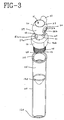
- Figure 3 represents a perspective view of the closure of the present invention shown unassembled.
- Figure 4 represents an enlarged cross-sectional view of the closure of the present invention shown unassembled.
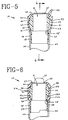
- Figure 5 represents a cross-sectional view of the closure of the present invention in an open state taken along lines 5-5 of Figure 1.
- Figure 6 represents a cross-sectional view of the closure of the present invention in an open state taken along lines 6-6 of Figure 5.
- Figure 7 represents a cross-sectional view of the closure of the present invention in a closed state taken along lines 7-7 of Figure 2.
- Figure 8 represents a cross-sectional view of the closure of the present invention in a closed state taken along lines 8-8 of Figure 7.
- Figure 9 represents an enlarged cross-sectional view showing a portion of the closure of the present invention in detail.
- Figure 10 represents a perspective view of the ball of the present invention, depicting the eccentric axle.
- Figure 11 represents a cross-sectional view of a socket in an alternate embodiment of the present invention.
- Figure 12 represents a perspective view of an alternate embodiment of the closure of the present invention shown unassembled in a closed state.
- Figure 13 represents a perspective view of the alternate embodiment depicted in Figure 12 shown unassembled in an open state.
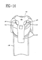
- Figure 14 represents a perspective view of a further embodiment of the closure of the present invention.
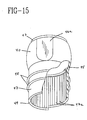
- Figure 15 represents a perspective view of a further embodiment of the closure of the present invention, showing a cut-out portion of cylindrical protrusion 47.
- Figure 16 represents an enlarged cross-sectional view of the closure of the present invention attached to a collection container.
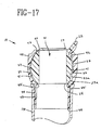
- Figure 17 represents a cross-sectional view of an alternate embodiment of the closure of the present invention in an open state.
- specimen collection container is used to represent any type of container useful for collecting, transferring, analyzing or storing a biological or non-biological sample, for example primary and secondary specimen tubes for blood collection and analysis.
- the present invention takes the form of a ball and socket closure for a collection container capable of providing an adequate seal, and which is capable of preventing or minimizing transfer of contaminants between the external environment and the internal contents of the container.
- a closure 10 is shown positioned over a blood collection tube 100, respectively, in an open and closed position.
- Closure 10 is adapted for interfitting engagement with collection tube 100 at open end 110 thereof.
- Collection tube 100 may be any type of collection tube known in the art, and may be constructed of any known material such as glass or, more preferably, a suitable plastic.
- collection tube 100 is a false bottom tube including open end 110 at the top thereof and an opposed open bottom end 120, with a conical bottom 130 located between open end 110 and bottom end 120.
- Conical bottom 130 provides collection tube 100 with an upper chamber 115 for holding small volumes of liquid.
- collection tube 100 can be used with standard holders and analyzer equipment without the need for such a pipette or probe to travel the full length of collection tube 100 to access the sample contained therein.
- Closure 10 includes a generally spherical-shaped socket 40 and a cylindrical protrusion 47 depending from a bottom end of socket 40.
- Cylindrical protrusion 47 is adapted for interfitting engagement within open end 110 of collection tube 100, thereby providing means for attaching closure 10 to collection tube 100.
- Cylindrical protrusion 47 may be adapted for interfitting engagement with collection tube 100 in any manner, for example by snap-fit, threaded engagement, and the like.
- cylindrical protrusion 47 includes a plurality of annular ribs 48 spaced along an outer surface thereof, to provide for fictional engagement with the inside surface of collection tube 100 at open end 110.
- annular ribs 48 provide for fictional engagement with an annular ring 118 provided on the inside surface of collection tube 100 at open end 110. As shown in Figure 16, such interfitting of annular ribs 48 and annular ring 118 provide for multiple positions of fictional securement of closure 10 within collection tube 100, while providing a fluid-tight seal for preventing fluid contained within collection tube 100 from passing between cylindrical portion 47 and open end 110 of collection tube 100. In this manner, closure 10 may be firmly fitted and attached to collection tube 100 in a liquid-tight manner, and may be easily removed from collection tube 100 if desired.
- cylindrical protrusion 47 may further include one or more projections 49 for alignment and orientation of closure 10 during assembly, for example, in a feeder bowl.
- closure 10 further includes a generally spherically-shaped ball 20 fitted within socket 40.
- Ball 20 includes a passageway 21 extending therethrough.
- passageway 21 is in the form of a cylindrical bore, which extends through ball 20 from a first open end 23 of ball 20 to an opposed second open end 24 of ball 20.
- Passageway 21 provides an opening through ball 20 for permitting access between the outside environment and upper chamber 115 of collection tube 100, as will be discussed in more detail herein.
- the internal diameter of passageway 21 should be large enough to allow access of a probe therethrough and to allow fluid flow therethrough. It is important, however, that the overall outside diameter of closure 10 must not be too large. For example, if the outside diameter of closure 10 or socket 40 is significantly larger than the outside diameter of a standard collection tube, collection tube 100 with closure 10 assembled thereon may not properly fit or function in conventional testing equipment. More particularly, closure 10 is particularly useful in testing environments where conventional covers would need to be removed from a collection container prior to testing of the sample. As such, collection tubes typically conform to a standard size to be useful with such equipment.
- closure 10 of the present invention may be used during analysis without the need to remove the entire closure 10 from collection tube 100
- closure 10 preferably is capable of fitting within the boundary of such standard size testing equipment without the need for removal thereof. Therefore, the outside diameter of closure 10 or socket 40 is preferably less than approximately 19.05 millimeters in order to properly function with standard equipment. With such an outside diameter, the internal diameter of passageway 21 is preferably approximately 10.5 millimeters.
- closure 10 may be of a sufficient diameter such that, when coupled to collection tube 100, closure 10 is capable of supporting collection tube 100 in various testing equipment such as storage racks, carousels, etc.
- Ball 20 further includes an axle 30.
- Axle 30 permits rotative movement of ball 20 within socket 40 about an axis between an open position and a closed position, as will be discussed in more detail herein.
- Axle 30 is preferably defined by a pair of opposed protrusions 31a and 31b on opposed surfaces of ball 20, as best seen in Figures 6 and 8.
- Opposed protrusions 31a and 31b may be cylindrical-shaped protrusions, or alternatively, may include drafted surfaces 32a and 32b, to corresponded with tapered surfaces 52a and 52b of socket 40, as will be discussed in further detail herein.
- axle 30 may be defined by a pair of opposed cavities on opposed surfaces of ball 20, which opposed cavities engage with opposed protrusions within socket 40.
- Socket 40 includes a first open end 43 defining a perimetrical opening at the top thereof which is open to the external environment and a second open end 44 at the bottom end thereof which is open to the interior of collection tube 100.
- First open end 43 of socket 40 may include a contoured pouring surface for facilitating pouring of the contents of collection tube 100.
- Socket 40 may be of a generally spherical external shape.
- socket 40 may include opposed planar sides 46a and 46b on the external surface thereof. Such opposed planar sides 46a and 46b permit ease in manufacturing of closure 10, and provide a means for alignment of closure 10 with a specific reference point during assembly or for alignment with a plurality of closures 10 during use in equipment such as storage racks, carousels, etc.
- Socket 40 further includes a ball-receiving internal surface 41, for interfitting engagement with the outside surface of ball 20.
- Ball 20 fits within socket 40 in a contacting relation between the external surface of ball 20 and the perimeter of first open end 43 of socket 40, so as to establish engagement between ball 20 and socket 40 at first open end 43.
- socket 40 further includes an annular ball seat 45.
- Ball seat 45 may be a separate component, or may be integral with socket 40 located at the lower portion of internal surface 41, thereby providing a seat for ball 20 when closure 10 is assembled.
- Ball seat 45 may be compressible and/or flexible, and is preferably constructed of an elastomeric material. Ball seat 45 provides for a seal between ball 20 and socket 40, as will be discussed herein. In order to provide additional sealing between ball 20 and socket 40, additional seals may be incorporated into closure 10.
- cylindrical protrusion 47 may include vertical drainage channels 47a on an inside surface thereof, as shown in Figure 15. Channels 47a direct fluid such as blood which remains on the inside wall of cylindrical protrusion 47 toward open end 48 of socket 40 and closure 10, as will be discussed in more detail herein.
- Internal surface 41 is a generally spherical-shaped hollow opening which accommodates the shape of ball 20.
- Internal surface 41 includes axle-support 50 for receiving axle 30 of ball 20.
- Axle-support 50 may comprised of recessed cavities 51a and 51b at diametrically opposed sides thereof.
- Such opposed cavities 51a and 51b provide for interfitting engagement with opposed protrusions 3 la and 31b of ball 20.
- opposed cavities 51a and 51b may include tapered surfaces 52a and 52b, respectively, therein for engagement with drafted surfaces 32a and 32b of ball 20.
- axle 30 provides for rotative movement of ball 20 thereabout within socket 40.
- axle support 50 may include opposed protrusions for interfitting engagement with such opposed cavities of ball 20.
- Opposed cavities 51a and 51b of socket 40 may further include a flat edge 53 on a wall surface of one or both thereof.
- Flat edge 53 frictionally engages opposed protrusions 3 la and 31b of ball 20 during rotative movement of ball 20 within socket 40.
- Flat edge 53 is capable of providing the operator with a positive feedback for establishing that ball 20 has been fully rotated to the open or closed position within socket 40, as will be discussed in more detail herein.
- Rotative movement of ball 20 about axle 30 can be effected manually by providing ball 20 with externally accessible means for rotation such as tab 22 extending from the surface of ball 22.
- Tab 22 provides a protrusion for effecting movement of ball 20 within socket 40 by an operator's finger or thumb.
- Tab 22 may include a contoured pouring surface on a surface thereof for facilitating pouring of the contents of collection tube 100.
- means for rotation of ball 20 within socket 40 can be in the form of a flap 22a, as depicted in Figures 12 and 13. Flap 22a may include ridges 26 therealong, which provide for frictional gripping of flap 22a by an operator's thumb of finger. During rotative movement of ball 20 within socket 40 between an open and closed position, flap 22a overrides an external surface portion of socket 40.
- Rotation of ball 20 about axle 30 results in the alignment of first open end 23 of ball 20 with first open end 43 of socket 40 as well as alignment of second open end 24 of ball 20 with second open end 44 of socket 40. As such, a path is established by way of passageway 21 extending through ball 20 between the outside environment and upper chamber 115 of collection tube 100.
- rotation of ball 20 about axle 30 accomplishes movement of ball 20 between an open position when passageway 21 is in alignment with the interior of collection tube 100 through the alignment of first open ends 23 and 43 and second open ends 23 and 44 (shown in Figures 1, 5 and 6), and a closed position when passageway 21 is out of alignment with the interior of collection tube 100 due to first open ends 23 and 43 and second open ends 23 and 44 being out of alignment with each other (shown in Figures 2, 7 and 8).
- Ball 20 is constructed and positioned within socket 40 so as to define an environment-contacting surface 27 and an opposed liquid-contacting surface 29.
- environment-contacting surface 27 When closure 10 is in a closed position, environment-contacting surface 27 is exposed to the external environment while liquid-contacting surface 29 is exposed to the interior of collection tube 100, i.e. upper chamber 115.
- environment-contacting surface 27 and liquid-contacting surface 29 are positioned within the spherical-shaped hollow opening of socket 40 which forms internal surface 41.
- environment-contacting surface 27 includes means for identifying when ball 20 is in a closed position. Such identifying means may include indicia distinguishing between an open position and a closed position.
- environment-contacting surface 27 may include a marking or wording thereon, or may include color coding signifying that the ball is in the closed position.
- such means for identifying when ball 20 is in a closed position includes the incorporation of a stop-indicating element on internal surface 41 of socket 40 for engagement with environment-contacting surface 27 when ball 20 is rotated to the closed position.
- internal surface 41 of socket 40 may include a protrusion for example, in the form of dimple 42 at a location adjacent first open end 43 of socket 40.
- Dimple 42 may include a small protrusion extending from the internal surface 41 of socket 40.
- dimple 42 provides an audible and tactile "click stop" feedback to the operator when environment-contacting surface 27 of ball 20 passes thereover, indicated that ball 20 has been fully rotated to the closed position.
- dimple 42 may include a protrusion in the form of a rib 42a extending along a length of internal surface 41 of socket 40, as shown in Figure 17.
- rib 42a provides an operator with an audible and tactile "click-stop" feedback to indicate that ball 20 has been fully rotated to both the open and closed positions, as will be discussed.
- U.S. Patent No. 2,032,776 discussed in the background, discloses a closure with a rotatable valve ball sitting within a boss which has a locking mechanism incorporating a projection on the ball.
- Such a closure is not effective for a ball and socket closure as in the present invention where socket 40 encompasses ball 20 in a tight manner about substantially the entire outer surface of ball 20.
- the outer surface of the ball would not rotate freely and easily within the surface of socket 40, as the projection would interfere with the proper interfitting of the ball within the socket.
- the outer surface of the ball at the projection would necessarily contact the inner surface of the socket, which is undesirable in many applications, particularly when biological samples are involved.
- axle 30 of ball 20 is defined by opposed protrusions 31a and 31b
- axle-support 50 of socket 40 is defined by opposed cavities 51a and 51b.
- axle 30 is received in axle-support 50, i.e., opposed protrusions 31a and 31b are supported within opposed cavities 51a and 51b.
- axle 30 and axle-support 50 are parallel and eccentric with respect to each other.
- axle 30 and axle-support 50 is preferably effected by off-setting axle 30 with respect to the true axis of ball 20.
- a true axis X represents the actual common central axis of closure 10, defined by the sphere of ball 20 and the spherical-shaped hollow opening defined by internal surface 41 of socket 40.
- True axis X is generally perpendicular and transverse to passageway 21 of ball 20.
- axle-support 50 defined by opposed cavities 51 and 51b of socket 40, is in alignment with true axis X.
- Axle 30, defined by opposed protrusions 31a and 31b of ball 20, may lie along a given eccentric axis X', which is also generally perpendicular and transverse to passageway 21, but positioned to be eccentric or off-set from true axis X.
- opposed protrusions 3 la and 31b are not directly aligned along the true axis X of ball 20, but are slightly offset therefrom, thus making axle 30 slightly eccentric to true axis X.
- Alignment of axle 30 with axle-support 50 by way of opposed protrusions 31a and 31b of ball 20 fitting within opposed cavities 51a and 51b of socket 40 aligns ball 20 within socket 40, with ball 20 being slightly offset from interior cavity 41 of socket 40.
- axle 30 provides for non-symmetric rotation of ball 20 within socket 40 between the open and closed positions. In essence, rotation of ball 20 about axle 30 results in a cam-like engagement of opposed protrusions 31a and 31b with opposed cavities 51a and 51b, due to the alignment of axle 30 with eccentric axis X'. Such eccentric positioning of axle 30 urges ball 20 into seated positioning with ball seat 45 so as to provide a liquid-tight seal at ball seat 45, particularly when ball 20 is in a closed position, and further assists in preventing transfer of contaminants between the external environment and the interior of collection tube 100, as will be discussed in more detail herein.
- axle-support 50 in an alternate embodiment of the present invention, can be effected by off-setting axle-support 50 with respect to true axis X.
- axle-support 50 defined by opposed cavities 51a and 51b of socket 40, may lie along a given eccentric axis Y', which is also generally perpendicular and transverse to passageway 21 of ball 20, but positioned to be eccentric or off-set from true axis X.
- opposed cavities 51a and 51b are not directly aligned along the true axis X, but are slightly offset therefrom, thus making axle-support 50 slightly eccentric to true axis X.
- axle 30 may be aligned with true axis X, since the eccentric nature of axle-support 50 provides for non-symmetric rotation of ball 20 within socket 40 between the open and closed positions, in a similar manner as in the preferred embodiment.
- axle 30 and axle-support 50 may be offset from or eccentric to true axis X. In such an embodiment, however, axle 30 and axle-support 50 must not be in alignment with each other but instead must remain eccentric with respect to each other in order to provide for non-symmetric rotation of ball 20 within socket 40 between the open and closed positions.
- Figures 5 and 6 show cross-sectional front and side views of the closure 10 of the present invention in an open position
- Figures 7 and 8 show cross-sectional front and side views in a closed position.
- ball 20 is positioned within socket 40 in a slightly offset manner when closure 10 is in the open position due to opposed protrusions 31a and 31b of ball 20 being aligned within opposed cavities 51a and 51b in socket 40 in an offset position.
- ball 20 is seated on ball seat 45 of socket 40 in a liquid-tight sealing manner in this open position, minimal force is being placed on ball 20 in the longitudinal direction. This provides for ease of rotational movement of ball 20 about axle 30, while maintaining a liquid-tight seal to prevent blood or other fluid contained within collection tube 100 from traveling past ball seat 45.
- environment-contacting surface 27 is preferably recessed from the general spherical shape of ball 20 to define a perimetrical edge 27a, such that when closure 10 is in an open position, annular space 37 is provided between environment-contacting surface 27 and internal surface 41 of socket 40, thus maintaining a non-contacting relation therebetween. This non-contacting relation prevents contamination between environment-contacting surface 27 and interior surface 41.
- closure 10 may be adapted for symmetric rotation of ball 20 within socket 40 about axle 30, or may be adapted for non-symmetric rotation of ball 20 within socket 40 about axle 30.
- closure 10 may include a separate locking mechanism for preventing rotational movement of ball 20 within socket 40, for example a clip, strap, band, or the like, for securing ball 20 in a closed position during transport or storage, or in an open position during use.
- a locking mechanism is preferably in the form of a clip 60, as shown in Figure 14.
- Clip 60 includes three arms 62 equally spaced from each other. Arms 62 overlap closure 10, with tab 22 of ball 20 interfitting within the space between two adjacent arms 62.
- Such clip 60 provides an effective yet simple mechanism for locking closure 10 in position.
- closure 10 including ball 20 fitted within socket 40 is provided for engagement at open end 110 of collection tube 100.
- Clip 60 is removed from closure 10 to permit rotational movement of ball 20 within socket 40.
- Rotational movement of ball 20 within socket 40 about axle 30 accomplishes opening and closing of closure 10.
- environment-contacting surface 27 is positioned within first open end 43 of socket 40 and is exposed to the external environment while liquid-contacting surface 29 of ball 20 is positioned for exposure to upper chamber 115 of collection tube 100.
- the external surface of ball 20 contacts ball seat 45 in a sealing engagement, thus preventing any fluid contained within collection tube 100 from passing beyond ball seat 45 and between ball 20 and socket 40.
- Full rotation of ball 20 within socket 40 is accomplished by moving tab 22 completely across first open end 43 of socket 40, with tab 22 resting on the perimeter of first open end 43.
- opposed protrusions 31a and 31b of ball 20 engage opposed cavities 51a and 51b of socket 40 in a cam-like fashion due to the eccentric nature of axle 30, thus slightly lifting ball 20 longitudinally within socket 40.
- This longitudinal lifting causes ball 20 to be slightly lifted from ball seat 45.
- ball seat 45 is flexible, ball seat 45 flexes with the longitudinal movement of ball 20, thereby maintaining a contacting relation between ball seat 45 and ball 20 to maintain a liquid-tight seal.
- This open position effects the alignment of first open end 23 of ball 20 with first open end 43 of socket 30 as well as alignment of second open end 24 of ball 20 with second open end 44 of socket 40, resulting in passageway 21 extending through ball 20 between the outside environment and upper chamber 115 of collection tube 100.
- This alignment establishes a path for insertion of a probe or for pouring of fluids contained within upper chamber 115, directly through passageway 21.
- closure 10 can be returned to its closed position by applying pressure to tab 22 in a direction opposite of that to open closure 10, i.e., in a direction toward passageway 21 of ball 22.
- pressure transmits a force to ball 20 about axle 30 in a similar manner as that exerted during opening of closure 10, thus causing ball 20 to rotate about axle 30 within socket 40 in an opposite direction as that used to open closure 10.
- This rotative movement causes liquid-contacting surface 29 to travel back across ball seat 45, to its original position where it is exposed to upper chamber 115 of collection tube 100.
- environment-contacting surface 27 causes environment-contacting surface 27 to travel back across the perimeter of first open end 43 of socket 40 to its original position where it is exposed to the external environment.
- environment-contacting surface 27 is recessed with respect to the overall sphere defining the shape of ball 20, it does not contact inside surface 41 of socket 40 during such travel.
- perimetrical edge 27a of environment-contacting surface 27 which defines the transition between the overall sphere-shape of ball 20 and the recessed portion of environment-contacting surface 27 contacts dimple 42 as it passes thereover.
- Such contacting provides for interference engagement therebetween resulting in an audible and tactile "click stop" feedback for the operator, thus providing an indication that ball 20 has been fully rotated within socket 40 to the closed position.
- Ball 20 and socket 40 can be made of any known materials useful for such purposes.
- both ball 20 and socket 40 are constructed of thermoplastic materials.
- socket 40 is constructed from an elastomeric-like material, with ball 20 being constructed of a more rigid material.
- socket 40 is made of a material selected from polyethylene or thermoplastic elastomer (TPE), and ball 20 is made of a material selected from polystyrene or polypropylene.
- TPE thermoplastic elastomer
- ball 20 is made of a material selected from polystyrene or polypropylene.
- Ball 20 and socket 40 can be manufactured using a variety of methods. Preferably, ball 20 and socket 40 are separately manufactured by molding procedures such as injection molding, and then assembled to form closure 10. Alternatively, ball 20 and socket 40 may be manufactured using a "dual-shot” or “two-shot” molding procedure, wherein ball 20 is fist molded and socket 40 is thereafter molded directly thereover. Various other molding and manufacturing methods are contemplated.
- the closure of the present invention provides a number of improvements over prior art closures and techniques.
- the closure of the present invention minimizes splatter of liquid samples contained within a collection container. Additionally, there is no need to remove the closure to access the interior region of the collection container. The closure, however, may be removed from the collection container if desired. While the closure is capable of a firm attachment to the collection container, it is still capable of rotating independently of the container without the need for removal.
- the use of such an integrated closure permits ease of use for technicians with less risk of contamination in that there is a lower tendency to leave the collection container open since opening and closing of the container can easily be accomplished with a single hand.
Abstract
Description
Claims (9)
- A closure for sealing an open end of a specimen collection container from the environment comprising:a socket mountable on said open end of said collection container for enclosing an interior region of said collection container, said socket including a ball receiving internal surface having a protrusion thereon; anda generally spherical-shaped ball mounted within said socket and at least partially enclosed thereby, said ball capable of rotative movement within said socket between an open position and a closed position, said ball including an external surface capable of interference engagement with said protrusion of said socket upon rotative movement of said ball between said open position and said closed position.
- A closure as in claim 1, wherein said protrusion includes a rib along said ball receiving internal surface.
- A closure as in claim 1, wherein said protrusion includes a dimple on said ball receiving interns surface.
- A closure as in claim 1, wherein said ball includes an environment-contacting surface exposed to an external environment when said ball is in said closed position, said environment-contacting surface being recessed with respect to said general spherical-shape of said ball to define a perimetrical edge therearound.
- A closure as in claim 4, wherein said socket includes an open upper end permitting exposure of said environment-contacting surface to said external environment when said ball is in said closed position.
- A closure as in claim 5, wherein said protrusion is located on said ball receiving internal surface of said socket at a position adjacent said open upper end of said socket.
- A closure as in claim 6, wherein said perimetrical edge of said ball and said protrusion of said socket are capable of interference engagement therebetween.
- A closure for sealing an open end of a specimen collection container from the environment comprising:a socket mountable on said open end of said collection container for enclosing an interior region of said collection container, said socket including a ball receiving internal surface having a protrusion thereon; anda generally spherical-shaped ball mounted within said socket, said ball capable of rotative movement between an open position and a closed position, said ball including an environment-contacting surface, an opposed specimen-contacting surface and a passageway extending therethrough, said passageway being aligned with said open end of said collection container when said ball is in said open position, said environment-contacting surface being exposed to an external environment and said specimen-contacting surface being exposed to said interior region of said collection container when said ball is in said closed position, said environment-contacting surface of said ball being recessed with respect to said general spherical-shape of said ball to define a perimetrical edge,wherein said environment-contacting surface does not contact said interior surface of said socket when said ball is in said open position, andwherein rotative movement of said ball within said socket between an open position and a closed position causes interference engagement between said perimetrical edge of said environment-contacting surface and said protrusion of said internal surface of said socket.
- A specimen collection chamber which includes a closure according to any preceding claim.
Applications Claiming Priority (2)
| Application Number | Priority Date | Filing Date | Title |
|---|---|---|---|
| US08/928,058 US6350415B1 (en) | 1997-09-12 | 1997-09-12 | Ball and socket closure for specimen collection container incorporating a dimple locking mechanism |
| US928058 | 1997-09-12 |
Publications (3)
| Publication Number | Publication Date |
|---|---|
| EP0901826A2 true EP0901826A2 (en) | 1999-03-17 |
| EP0901826A3 EP0901826A3 (en) | 2000-01-19 |
| EP0901826B1 EP0901826B1 (en) | 2004-03-24 |
Family
ID=25455654
Family Applications (1)
| Application Number | Title | Priority Date | Filing Date |
|---|---|---|---|
| EP98307061A Expired - Lifetime EP0901826B1 (en) | 1997-09-12 | 1998-09-02 | Ball and socket closure for specimen collection container incorporating a locking mechanism |
Country Status (5)
| Country | Link |
|---|---|
| US (1) | US6350415B1 (en) |
| EP (1) | EP0901826B1 (en) |
| JP (1) | JP3052287B2 (en) |
| AU (1) | AU8320298A (en) |
| DE (1) | DE69822577T2 (en) |
Cited By (2)
| Publication number | Priority date | Publication date | Assignee | Title |
|---|---|---|---|---|
| US7648037B2 (en) | 2005-08-04 | 2010-01-19 | Olympus Corporation | Lid structure of reagent container |
| EP2199802A1 (en) * | 2008-02-07 | 2010-06-23 | ARKRAY, Inc. | Container and analysis container using the same |
Families Citing this family (24)
| Publication number | Priority date | Publication date | Assignee | Title |
|---|---|---|---|---|
| CN1292717C (en) * | 2002-01-22 | 2007-01-03 | 杰富意钢铁株式会社 | Ceramic coated medical equipment and biological research equipment and its producing method |
| US9052254B2 (en) | 2006-01-13 | 2015-06-09 | The Bode Technology Group, Inc. | Evidence collector with integral quantified reagents and method of modulating specimen drying time |
| CA2649329C (en) * | 2006-04-14 | 2014-09-09 | The Bode Technology Group, Inc. | Low pressure sample collection apparatus |
| US20100218726A1 (en) * | 2009-03-01 | 2010-09-02 | Hope Bari Adams | Animal water bottle cap dispenser device |
| US7985188B2 (en) | 2009-05-13 | 2011-07-26 | Cv Holdings Llc | Vessel, coating, inspection and processing apparatus |
| PL2251454T3 (en) | 2009-05-13 | 2014-12-31 | Sio2 Medical Products Inc | Vessel coating and inspection |
| US9458536B2 (en) | 2009-07-02 | 2016-10-04 | Sio2 Medical Products, Inc. | PECVD coating methods for capped syringes, cartridges and other articles |
| US11624115B2 (en) | 2010-05-12 | 2023-04-11 | Sio2 Medical Products, Inc. | Syringe with PECVD lubrication |
| US9878101B2 (en) | 2010-11-12 | 2018-01-30 | Sio2 Medical Products, Inc. | Cyclic olefin polymer vessels and vessel coating methods |
| US9272095B2 (en) | 2011-04-01 | 2016-03-01 | Sio2 Medical Products, Inc. | Vessels, contact surfaces, and coating and inspection apparatus and methods |
| US11116695B2 (en) | 2011-11-11 | 2021-09-14 | Sio2 Medical Products, Inc. | Blood sample collection tube |
| US10189603B2 (en) | 2011-11-11 | 2019-01-29 | Sio2 Medical Products, Inc. | Passivation, pH protective or lubricity coating for pharmaceutical package, coating process and apparatus |
| EP2846755A1 (en) | 2012-05-09 | 2015-03-18 | SiO2 Medical Products, Inc. | Saccharide protective coating for pharmaceutical package |
| CA2890066C (en) | 2012-11-01 | 2021-11-09 | Sio2 Medical Products, Inc. | Coating inspection method |
| US9903782B2 (en) | 2012-11-16 | 2018-02-27 | Sio2 Medical Products, Inc. | Method and apparatus for detecting rapid barrier coating integrity characteristics |
| US9764093B2 (en) | 2012-11-30 | 2017-09-19 | Sio2 Medical Products, Inc. | Controlling the uniformity of PECVD deposition |
| WO2014085348A2 (en) | 2012-11-30 | 2014-06-05 | Sio2 Medical Products, Inc. | Controlling the uniformity of pecvd deposition on medical syringes, cartridges, and the like |
| US9662450B2 (en) | 2013-03-01 | 2017-05-30 | Sio2 Medical Products, Inc. | Plasma or CVD pre-treatment for lubricated pharmaceutical package, coating process and apparatus |
| CN105392916B (en) | 2013-03-11 | 2019-03-08 | Sio2医药产品公司 | Coat packaging materials |
| US9937099B2 (en) | 2013-03-11 | 2018-04-10 | Sio2 Medical Products, Inc. | Trilayer coated pharmaceutical packaging with low oxygen transmission rate |
| US9863042B2 (en) | 2013-03-15 | 2018-01-09 | Sio2 Medical Products, Inc. | PECVD lubricity vessel coating, coating process and apparatus providing different power levels in two phases |
| WO2015148471A1 (en) | 2014-03-28 | 2015-10-01 | Sio2 Medical Products, Inc. | Antistatic coatings for plastic vessels |
| US10300486B2 (en) * | 2015-07-17 | 2019-05-28 | Stat-Diagnostica & Innovation, S.L. | Dry chemistry container |
| BR112018003051B1 (en) | 2015-08-18 | 2022-12-06 | Sio2 Medical Products, Inc | VACUUM BLOOD COLLECTION TUBE |
Citations (2)
| Publication number | Priority date | Publication date | Assignee | Title |
|---|---|---|---|---|
| US2032776A (en) | 1934-02-08 | 1936-03-03 | Henry E Van Ness | Dispensing container and closure therefor |
| US4181246A (en) | 1978-03-24 | 1980-01-01 | Norris Gilbert H | Closure for a collapsible tube |
Family Cites Families (36)
| Publication number | Priority date | Publication date | Assignee | Title |
|---|---|---|---|---|
| US1430313A (en) | 1920-10-25 | 1922-09-26 | Millity Vlada | Bottle closure |
| US1726642A (en) | 1926-10-09 | 1929-09-03 | Frank L Betts | Tube container and closure therefor |
| US1691811A (en) | 1927-03-11 | 1928-11-13 | Johnson Elmer | Valve mechanism |
| US1747550A (en) | 1927-08-17 | 1930-02-18 | Klimburg Rudolf | Closing device |
| US1882180A (en) | 1932-01-28 | 1932-10-11 | Davidson Lawrence | Cap or closure for receptacles |
| US2126814A (en) | 1932-07-05 | 1938-08-16 | Nokap Closures U S A Inc | Method and apparatus for making containers |
| GB448119A (en) | 1934-11-30 | 1936-06-02 | James Rest | Improvements in or relating to closures for bottles, collapsible tubes and like containers |
| US2030696A (en) | 1935-02-25 | 1936-02-11 | Raymond Schmidt | Dispensing container |
| GB463118A (en) | 1935-09-27 | 1937-03-22 | James Rest | Improvements in or relating to closure members for bottles or other containers for fluid or like materials |
| US2135848A (en) | 1936-04-25 | 1938-11-08 | Albert R Johnson | Salt and pepper shaker and the like |
| GB479200A (en) | 1936-08-01 | 1938-02-01 | James Rest | Improvements in or relating to closures for bottles, collapsible tubes and like containers |
| US2120510A (en) | 1937-03-05 | 1938-06-14 | Frank O Rhoads | Rotary tube closure |
| US2209050A (en) | 1937-04-17 | 1940-07-23 | No Kap Closures U S A Inc | Nozzle closure means for containers |
| US2558671A (en) | 1947-07-17 | 1951-06-26 | Henry H Cherry | Valve assembly with spherical shaped valve element having a passage therethrough for collapsible tubes |
| US2749566A (en) | 1952-09-04 | 1956-06-12 | Bristol Myers Co | Dispenser |
| US2779519A (en) | 1953-03-02 | 1957-01-29 | Rossetti Rene | Closing device for tubular duct |
| US2805801A (en) | 1953-11-06 | 1957-09-10 | Jacobs William | Container with rotary closure |
| US2885128A (en) | 1957-11-12 | 1959-05-05 | Zimmerli Adolf | Container closure |
| US2990980A (en) | 1958-08-11 | 1961-07-04 | Container Corp | Dispensing container closure |
| US3703249A (en) | 1970-05-08 | 1972-11-21 | Edward Benjamin Middleton | Rotatable opening container closure |
| CH537318A (en) | 1971-03-19 | 1973-07-13 | Schneider Urs | Safety lock on a container |
| US3703250A (en) | 1971-04-12 | 1972-11-21 | Edward B Middleton | Closure having geared rotatable ball valve |
| US3702165A (en) | 1971-07-28 | 1972-11-07 | Us Cap & Closure Inc | Child-proof dispensing closures |
| JPS548190B2 (en) | 1973-05-16 | 1979-04-13 | ||
| US3863818A (en) | 1973-12-17 | 1975-02-04 | Polytop Corp | Dispensing closures with integral spout latches |
| US4390111A (en) | 1982-02-08 | 1983-06-28 | Robbins Scientific Corporation | Sealable vial |
| ES266599Y (en) | 1982-06-18 | 1983-11-16 | "DEVICE APPLICABLE TO THE CONDUCT OF ANALYSIS". | |
| DE3400660A1 (en) * | 1984-01-11 | 1985-07-18 | Rainer 8963 Waltenhofen Achterholt | Closure head for containers |
| JP2677986B2 (en) | 1986-06-21 | 1997-11-17 | ロ−ム株式会社 | Recovery time reduction circuit |
| IT1233820B (en) | 1989-03-07 | 1992-04-17 | Taplast Snc Di Evans Santagiul | CAP WITH DISPENSER FOR LIQUIDS. |
| JPH05170256A (en) | 1991-12-16 | 1993-07-09 | Toshiyuki Tsuda | Pour spout structure for container |
| US5225165A (en) | 1992-05-11 | 1993-07-06 | Brandeis University | Microcentrifuge tube with upwardly projecting lid extension |
| IT1274578B (en) | 1992-05-13 | 1997-07-17 | Francesco Leopardi | SAFETY CLOSURE DEVICE FOR CONTAINERS FOR ORGANIC LIQUIDS |
| US6152189A (en) | 1993-03-30 | 2000-11-28 | Isco, Inc. | Sampler |
| BR9404733A (en) | 1994-11-24 | 1995-08-01 | Sobral Invicta Sa | Improvement in lid, with serving device, for thermal containers |
| US6161712A (en) | 1996-07-22 | 2000-12-19 | Becton Dickinson And Company | Ball and socket closure |
-
1997
- 1997-09-12 US US08/928,058 patent/US6350415B1/en not_active Expired - Lifetime
-
1998
- 1998-09-02 DE DE69822577T patent/DE69822577T2/en not_active Expired - Lifetime
- 1998-09-02 EP EP98307061A patent/EP0901826B1/en not_active Expired - Lifetime
- 1998-09-09 AU AU83202/98A patent/AU8320298A/en not_active Abandoned
- 1998-09-14 JP JP10260440A patent/JP3052287B2/en not_active Expired - Lifetime
Patent Citations (2)
| Publication number | Priority date | Publication date | Assignee | Title |
|---|---|---|---|---|
| US2032776A (en) | 1934-02-08 | 1936-03-03 | Henry E Van Ness | Dispensing container and closure therefor |
| US4181246A (en) | 1978-03-24 | 1980-01-01 | Norris Gilbert H | Closure for a collapsible tube |
Cited By (4)
| Publication number | Priority date | Publication date | Assignee | Title |
|---|---|---|---|---|
| US7648037B2 (en) | 2005-08-04 | 2010-01-19 | Olympus Corporation | Lid structure of reagent container |
| EP2199802A1 (en) * | 2008-02-07 | 2010-06-23 | ARKRAY, Inc. | Container and analysis container using the same |
| EP2199802A4 (en) * | 2008-02-07 | 2011-10-05 | Arkray Inc | Container and analysis container using the same |
| CN101680907B (en) * | 2008-02-07 | 2013-06-05 | 爱科来株式会社 | Container and analysis container using the same |
Also Published As
| Publication number | Publication date |
|---|---|
| US6350415B1 (en) | 2002-02-26 |
| EP0901826A3 (en) | 2000-01-19 |
| JPH11171218A (en) | 1999-06-29 |
| JP3052287B2 (en) | 2000-06-12 |
| DE69822577D1 (en) | 2004-04-29 |
| EP0901826B1 (en) | 2004-03-24 |
| AU8320298A (en) | 1999-03-25 |
| DE69822577T2 (en) | 2004-08-05 |
Similar Documents
| Publication | Publication Date | Title |
|---|---|---|
| EP0901826B1 (en) | Ball and socket closure for specimen collection container incorporating a locking mechanism | |
| EP0901825B1 (en) | Ball and socket closure for specimen collection container incorporating an integral flexible seal | |
| US6139802A (en) | Ball and socket closure for specimen collection container incorporating a resilient elastomeric seal | |
| EP0901827B1 (en) | Ball and socket closure for specimen collection container | |
| US5972297A (en) | Ball and socket closure for specimen collection container incorporating a septum | |
| US6161712A (en) | Ball and socket closure | |
| GB2117917A (en) | Apparatus for microscopic examination of a specimen | |
| EP0908237A2 (en) | Ball and socket closure for specimen collection container incorporating a pouring spout | |
| JP3071174U (en) | Ball and socket lid for sample collection container incorporating elastic elastomer seal |
Legal Events
| Date | Code | Title | Description |
|---|---|---|---|
| PUAI | Public reference made under article 153(3) epc to a published international application that has entered the european phase |
Free format text: ORIGINAL CODE: 0009012 |
|
| AK | Designated contracting states |
Kind code of ref document: A2 Designated state(s): DE FR GB IT |
|
| AX | Request for extension of the european patent |
Free format text: AL;LT;LV;MK;RO;SI |
|
| PUAL | Search report despatched |
Free format text: ORIGINAL CODE: 0009013 |
|
| AK | Designated contracting states |
Kind code of ref document: A3 Designated state(s): AT BE CH CY DE DK ES FI FR GB GR IE IT LI LU MC NL PT SE |
|
| AX | Request for extension of the european patent |
Free format text: AL;LT;LV;MK;RO;SI |
|
| 17P | Request for examination filed |
Effective date: 20000313 |
|
| AKX | Designation fees paid |
Free format text: DE FR GB IT |
|
| 17Q | First examination report despatched |
Effective date: 20021223 |
|
| RTI1 | Title (correction) |
Free format text: BALL AND SOCKET CLOSURE FOR SPECIMEN COLLECTION CONTAINER INCORPORATING A LOCKING MECHANISM |
|
| GRAP | Despatch of communication of intention to grant a patent |
Free format text: ORIGINAL CODE: EPIDOSNIGR1 |
|
| RTI1 | Title (correction) |
Free format text: BALL AND SOCKET CLOSURE FOR SPECIMEN COLLECTION CONTAINER INCORPORATING A LOCKING MECHANISM |
|
| GRAS | Grant fee paid |
Free format text: ORIGINAL CODE: EPIDOSNIGR3 |
|
| GRAA | (expected) grant |
Free format text: ORIGINAL CODE: 0009210 |
|
| RIN1 | Information on inventor provided before grant (corrected) |
Inventor name: BIRKLAND, KATHERINE Inventor name: GOTTLIEB, ROBERT Inventor name: SAVITZ, STEVE Inventor name: CARONO, DON Inventor name: NIERMANN, VOLKER |
|
| AK | Designated contracting states |
Kind code of ref document: B1 Designated state(s): DE FR GB IT |
|
| REG | Reference to a national code |
Ref country code: GB Ref legal event code: FG4D |
|
| RIC1 | Information provided on ipc code assigned before grant |
Ipc: 7A 61B 5/145 - Ipc: 7B 01L 3/14 A |
|
| REF | Corresponds to: |
Ref document number: 69822577 Country of ref document: DE Date of ref document: 20040429 Kind code of ref document: P |
|
| ET | Fr: translation filed | ||
| PLBE | No opposition filed within time limit |
Free format text: ORIGINAL CODE: 0009261 |
|
| STAA | Information on the status of an ep patent application or granted ep patent |
Free format text: STATUS: NO OPPOSITION FILED WITHIN TIME LIMIT |
|
| 26N | No opposition filed |
Effective date: 20041228 |
|
| PGFP | Annual fee paid to national office [announced via postgrant information from national office to epo] |
Ref country code: IT Payment date: 20060930 Year of fee payment: 9 |
|
| PG25 | Lapsed in a contracting state [announced via postgrant information from national office to epo] |
Ref country code: IT Free format text: LAPSE BECAUSE OF NON-PAYMENT OF DUE FEES Effective date: 20070902 |
|
| REG | Reference to a national code |
Ref country code: DE Ref legal event code: R082 Ref document number: 69822577 Country of ref document: DE Representative=s name: HASELTINE LAKE LLP, DE |
|
| REG | Reference to a national code |
Ref country code: FR Ref legal event code: PLFP Year of fee payment: 19 |
|
| REG | Reference to a national code |
Ref country code: FR Ref legal event code: PLFP Year of fee payment: 20 |
|
| PGFP | Annual fee paid to national office [announced via postgrant information from national office to epo] |
Ref country code: GB Payment date: 20170821 Year of fee payment: 20 Ref country code: DE Payment date: 20170821 Year of fee payment: 20 Ref country code: FR Payment date: 20170822 Year of fee payment: 20 |
|
| REG | Reference to a national code |
Ref country code: DE Ref legal event code: R071 Ref document number: 69822577 Country of ref document: DE |
|
| REG | Reference to a national code |
Ref country code: GB Ref legal event code: PE20 Expiry date: 20180901 |
|
| PG25 | Lapsed in a contracting state [announced via postgrant information from national office to epo] |
Ref country code: GB Free format text: LAPSE BECAUSE OF EXPIRATION OF PROTECTION Effective date: 20180901 |