EP0902255A2 - Angle sensor - Google Patents
Angle sensor Download PDFInfo
- Publication number
- EP0902255A2 EP0902255A2 EP98116950A EP98116950A EP0902255A2 EP 0902255 A2 EP0902255 A2 EP 0902255A2 EP 98116950 A EP98116950 A EP 98116950A EP 98116950 A EP98116950 A EP 98116950A EP 0902255 A2 EP0902255 A2 EP 0902255A2
- Authority
- EP
- European Patent Office
- Prior art keywords
- code ring
- angle sensor
- angle
- sensor according
- code
- Prior art date
- Legal status (The legal status is an assumption and is not a legal conclusion. Google has not performed a legal analysis and makes no representation as to the accuracy of the status listed.)
- Granted
Links
- 230000004888 barrier function Effects 0.000 claims abstract description 15
- 239000003999 initiator Substances 0.000 claims abstract description 9
- 238000011156 evaluation Methods 0.000 claims abstract description 7
- 238000001514 detection method Methods 0.000 claims description 8
- 230000005355 Hall effect Effects 0.000 claims description 2
- 230000035945 sensitivity Effects 0.000 claims 3
- 230000005693 optoelectronics Effects 0.000 claims 2
- 239000003086 colorant Substances 0.000 claims 1
- 230000010287 polarization Effects 0.000 claims 1
- 230000003595 spectral effect Effects 0.000 claims 1
- 230000002349 favourable effect Effects 0.000 description 2
- 238000009434 installation Methods 0.000 description 2
- NMWSKOLWZZWHPL-UHFFFAOYSA-N 3-chlorobiphenyl Chemical compound ClC1=CC=CC(C=2C=CC=CC=2)=C1 NMWSKOLWZZWHPL-UHFFFAOYSA-N 0.000 description 1
- 101001082832 Saccharomyces cerevisiae (strain ATCC 204508 / S288c) Pyruvate carboxylase 2 Proteins 0.000 description 1
- 230000005540 biological transmission Effects 0.000 description 1
- 239000004020 conductor Substances 0.000 description 1
- 238000013016 damping Methods 0.000 description 1
- 238000001914 filtration Methods 0.000 description 1
- 230000005415 magnetization Effects 0.000 description 1
- 238000005259 measurement Methods 0.000 description 1
- 238000010606 normalization Methods 0.000 description 1
- 230000008054 signal transmission Effects 0.000 description 1
- 238000004804 winding Methods 0.000 description 1
Images
Classifications
-
- B—PERFORMING OPERATIONS; TRANSPORTING
- B62—LAND VEHICLES FOR TRAVELLING OTHERWISE THAN ON RAILS
- B62D—MOTOR VEHICLES; TRAILERS
- B62D15/00—Steering not otherwise provided for
- B62D15/02—Steering position indicators ; Steering position determination; Steering aids
-
- G—PHYSICS
- G01—MEASURING; TESTING
- G01D—MEASURING NOT SPECIALLY ADAPTED FOR A SPECIFIC VARIABLE; ARRANGEMENTS FOR MEASURING TWO OR MORE VARIABLES NOT COVERED IN A SINGLE OTHER SUBCLASS; TARIFF METERING APPARATUS; MEASURING OR TESTING NOT OTHERWISE PROVIDED FOR
- G01D5/00—Mechanical means for transferring the output of a sensing member; Means for converting the output of a sensing member to another variable where the form or nature of the sensing member does not constrain the means for converting; Transducers not specially adapted for a specific variable
- G01D5/12—Mechanical means for transferring the output of a sensing member; Means for converting the output of a sensing member to another variable where the form or nature of the sensing member does not constrain the means for converting; Transducers not specially adapted for a specific variable using electric or magnetic means
- G01D5/244—Mechanical means for transferring the output of a sensing member; Means for converting the output of a sensing member to another variable where the form or nature of the sensing member does not constrain the means for converting; Transducers not specially adapted for a specific variable using electric or magnetic means influencing characteristics of pulses or pulse trains; generating pulses or pulse trains
- G01D5/249—Mechanical means for transferring the output of a sensing member; Means for converting the output of a sensing member to another variable where the form or nature of the sensing member does not constrain the means for converting; Transducers not specially adapted for a specific variable using electric or magnetic means influencing characteristics of pulses or pulse trains; generating pulses or pulse trains using pulse code
- G01D5/2492—Pulse stream
-
- G—PHYSICS
- G01—MEASURING; TESTING
- G01D—MEASURING NOT SPECIALLY ADAPTED FOR A SPECIFIC VARIABLE; ARRANGEMENTS FOR MEASURING TWO OR MORE VARIABLES NOT COVERED IN A SINGLE OTHER SUBCLASS; TARIFF METERING APPARATUS; MEASURING OR TESTING NOT OTHERWISE PROVIDED FOR
- G01D5/00—Mechanical means for transferring the output of a sensing member; Means for converting the output of a sensing member to another variable where the form or nature of the sensing member does not constrain the means for converting; Transducers not specially adapted for a specific variable
- G01D5/26—Mechanical means for transferring the output of a sensing member; Means for converting the output of a sensing member to another variable where the form or nature of the sensing member does not constrain the means for converting; Transducers not specially adapted for a specific variable characterised by optical transfer means, i.e. using infrared, visible, or ultraviolet light
- G01D5/32—Mechanical means for transferring the output of a sensing member; Means for converting the output of a sensing member to another variable where the form or nature of the sensing member does not constrain the means for converting; Transducers not specially adapted for a specific variable characterised by optical transfer means, i.e. using infrared, visible, or ultraviolet light with attenuation or whole or partial obturation of beams of light
- G01D5/34—Mechanical means for transferring the output of a sensing member; Means for converting the output of a sensing member to another variable where the form or nature of the sensing member does not constrain the means for converting; Transducers not specially adapted for a specific variable characterised by optical transfer means, i.e. using infrared, visible, or ultraviolet light with attenuation or whole or partial obturation of beams of light the beams of light being detected by photocells
- G01D5/347—Mechanical means for transferring the output of a sensing member; Means for converting the output of a sensing member to another variable where the form or nature of the sensing member does not constrain the means for converting; Transducers not specially adapted for a specific variable characterised by optical transfer means, i.e. using infrared, visible, or ultraviolet light with attenuation or whole or partial obturation of beams of light the beams of light being detected by photocells using displacement encoding scales
- G01D5/34707—Scales; Discs, e.g. fixation, fabrication, compensation
- G01D5/34715—Scale reading or illumination devices
Definitions
- the invention relates to a corresponding to the preamble of the main claim designed angle sensor.
- an angle sensor of the generic type is already in the EP 0 774 648 A1, in which a reduction in the space requirement and A simplification of the assembly is realized in that the Code ring with n (n> 1) geometrically identical, each the same Coding ring segments is provided and the Sensor elements as well as each code ring segment over one Extend circumferential angle range from (360 / n °).
- the entire angle sensor is reduced to a circumferential segment, so that the space requirement on this segment of the full circle is reduced. Installation is considerably simplified since the segment can be mounted on the side of the casing tube.
- the code ring segments in conjunction with m sensor elements which have the same angular distance from one another, produce a single-step, linked m-bit code by which the angular position within a segment is clearly identified. The detection of the angle beyond a segment takes place, among other things, on the basis of an initialization of the system by a reference value and subsequent (digital) counting of the segments according to the direction of rotation.
- the light barriers are preferably constructed such that a fork light barriers arranged on a printed circuit board provided in a plane perpendicular to the axis of the device are used as the sensor element and a code diaphragm ring arranged in an annular gap formed by the light barriers or as a code ring in a vertical direction Reflection light barriers arranged on the plane of the device aligned with the plane of the device and a code reflection ring are provided as the code ring.
- the reflection light barriers can be assigned to the outer and / or the inner circumference of the code reflection ring.
- a magnetic measurement is made possible as sensor elements magnetic field sensors each cooperating with a magnet and as a code ring a soft magnetic code diaphragm ring are provided, it being favorable if each magnetic field sensor and the associated magnet on one Side of the soft magnetic code aperture ring arranged one behind the other are.
- Another magnetic arrangement can be realized in this known angle sensor in that as Sensor elements magnetic field sensors and as a code ring permanent magnetic ring with coded magnetization are provided.
- the present invention is therefore based on the object at the outset to further develop the described angle sensor such that normalization the same when starting up for the first time or after a power failure in assigned supply network with the least effort, but still flawless, is possible.
- the task is performed in the characterizing part of Main claim specified features solved.
- An advantage of such an embodiment is that in the simplest case only one initiator matched to the existing components, otherwise the same Configuration is required.
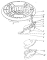
- stator 1 is a segment-shaped, the steering spindle of a motor vehicle tangent stator 1 for the sake of simplicity shown steering device or the associated jacket tube rotatably over only partially indicated fasteners installed.
- Printed circuit board 2 held the same outer contour as the stator itself having.
- the PCB housing part 1a available.
- the stator 1 has furthermore a segment-shaped holder 3 aligned with the printed circuit board 2 to accommodate six at equal angular intervals of 12 ° each arranged light barriers 4.
- the transmission and reception elements of the Light barriers 4 are directly connected to the conductor tracks of the printed circuit board 2 contacted and lie on the two sides of one in the holder 3rd existing annular gap 5 opposite.
- the annular gap 5 is concentric aligned to the axis of the steering spindle associated with the steering device.
- a rotor disk is connected to the steering spindle or to it Steering wheel coupled and as a code ring 7 with five each one Circumferential angle of 72 ° extending, identical aperture ring segments 8 trained.
- the aperture ring segments are on rotation of the code ring 7 moved through the annular gap 5 and generate in Connection with the light barriers 4 a one-step concatenated code. This code enables accurate counting by continuous counting Position determination, even with several revolutions of the Steering wheel.
- the angle sensor shown is advantageously part of a so-called winding spring cassette, which is used for the transmission of signals or Energy from a fixed to a rotatable part of the steering device is provided by motor vehicles.
- the angle sensor after its installation for the first Commissioning or new standardization after a power failure is at the segment-shaped holder 3 in a chamber 3a provided therefor magnetic field sensitive, preferably based on Hall effect Sensor element 9 used, which with an existing on the code ring 7, as Initiator 10 serving, permanent magnetic component cooperates.
- the angle sensor can be standardized in that the steering wheel is brought into one of its two end positions and then when the steering wheel is rotated into the opposite end position, both the code sequence detected by the sensor elements 4 and the signals supplied by the additional sensor element 9 are also registered. Since the position of the initiator causing the signals of the additional sensor element 9 on the code diaphragm ring is known, the position of the diaphragm ring segments with respect to a circle circumference for the evaluation unit can also be determined by correlating these signals with the code sequence detected by the sensor elements 4. By knowing the end positions of the steering wheel rotation, the position of the diaphragm ring segments with respect to the entire range of motion is also known. Since the end position of the steering wheel rotation is defined with tolerances ⁇ 360 ° with respect to the central position of the steering wheel, the segment containing the central position of the steering wheel is thus known and the LWS is thus initialized in a clear manner.
- the magnetic field-sensitive component 9 with at least one light barrier, which is likewise arranged on the stator 1 or the associated segment-shaped holder 3.
- the light barrier can be designed either as a fork or a reflection light barrier, and either an aperture element on the code ring or a reflection zone provided on the code ring can be used as the initiator. It is particularly expedient if an element of an aperture ring segment that is already present for angular detection has, for example, a filtering or damping characteristic, so that the signal change associated therewith can be detected by an existing and / or an additional sensor element.
Abstract
Description
Die Erfindung betrifft einen entsprechend dem Oberbegriff des Hauptanspruchs konzipierten Winkelsensor.The invention relates to a corresponding to the preamble of the main claim designed angle sensor.
Durch die DE 43 00 663 C1 ist ein Winkelsensor bekanntgeworden, wobei eine Leiterplatte vorhanden ist, die sich über einen Vollkreis erstreckt. Infolgedessen benötigt dieser Winkelsensor viel Platz. Die Montage ist zudem relativ aufwendig, da die Leiterplatte über die als Lenk-Einrichtung eingesetzten Mittel montiert werden muß.An angle sensor has become known from DE 43 00 663 C1, one of which Printed circuit board is present, which extends over a full circle. Consequently this angle sensor requires a lot of space. The assembly is also relative expensive because the circuit board on the means used as a steering device must be installed.
Darüber hinaus ist ein Winkelsensor der gattungsgemäßen Art bereits in der
EP 0 774 648 A1 offenbart, bei dem eine Reduzierung des Platzbedarfes und
eine Vereinfachung der Montage realisiert ist und zwar dadurch, daß der
Codering mit n (n>1) geometrisch gleich aufgebauten, jeweils eine gleiche
Codierung aufweisenden Codering-Segmenten versehen ist und die
Sensorelemente sowie jedes Codering-Segment sich über einen
Umfangswinkelbereich von (360/n°) erstrecken. In addition, an angle sensor of the generic type is already in the
Dadurch ist der gesamte Winkelsensor auf ein Umfangsegment reduziert, so
daß der Platzbedarf auf dieses Segment des Vollkreises herabgesetzt ist. Die
Montage ist wesentlich vereinfacht, da das Segment seitlich am Mantelrohr
montiert werden kann.
Die Codering-Segmente rufen dabei in Verbindung mit m untereinander einen
gleichen Winkelabstand aufweisenden Sensorelementen einen einschrittigen,
verketteten m-Bit-Code hervor, durch den die Winkelposition innerhalb eines
Segmentes eindeutig gekennzeichnet ist. Die Erfassung des Winkels über ein
Segment hinaus erfolgt unter anderem aufgrund einer Initialisierung des
Systems durch einen Referenzwert und anschließende drehrichtungsgemäße
(digitale) Zählung der Segmente.As a result, the entire angle sensor is reduced to a circumferential segment, so that the space requirement on this segment of the full circle is reduced. Installation is considerably simplified since the segment can be mounted on the side of the casing tube.
The code ring segments, in conjunction with m sensor elements which have the same angular distance from one another, produce a single-step, linked m-bit code by which the angular position within a segment is clearly identified. The detection of the angle beyond a segment takes place, among other things, on the basis of an initialization of the system by a reference value and subsequent (digital) counting of the segments according to the direction of rotation.
Die Lichtschranken sind bei diesem Gegenstand vorzugsweise so aufgebaut,
daß als Sensorelement entweder auf einer in einer senkrecht zur Achse der
Einrichtung ausgerichteten Ebene vorgesehenen Leiterplatte angeordnete
Gabel-Lichtschranken und als Codering ein in einem von den Lichtschranken
gebildeten Ringspalt angeordneter Codeblendenring oder auf einer in einer
senkrecht zur Achse der Einrichtung ausgerichteten Ebene vorgesehenen
Leiterplatte angeordnete Reflexions-Lichtschranken und als Codering ein
Codereflexionsring vorgesehen sind.
Dabei können die Reflexions-Lichtschranken dem äußeren und/oder dem
inneren Umfang des Codereflexionsringes zugeordnet sein.In this object, the light barriers are preferably constructed such that a fork light barriers arranged on a printed circuit board provided in a plane perpendicular to the axis of the device are used as the sensor element and a code diaphragm ring arranged in an annular gap formed by the light barriers or as a code ring in a vertical direction Reflection light barriers arranged on the plane of the device aligned with the plane of the device and a code reflection ring are provided as the code ring.
The reflection light barriers can be assigned to the outer and / or the inner circumference of the code reflection ring.
Eine magnetische Messung wird dadurch ermöglicht, daß als Sensorelemente mit jeweils einem Magnet kooperierende Magnetfeldsensoren und als Codering ein weichmagnetischer Codeblendenring vorgesehen sind, wobei es günstig ist, wenn jeder Magnetfeldsensor und der jeweils zugehörige Magnet auf einer Seite des weichmagnetischen Codeblendenrings hintereinander angeordnet sind. Es ist aber auch möglich, die Magnetfeldsensoren derart auszubilden, daß jeder Magnetfeldsensor und der jeweils zugehörige Magnet sich gegenüberliegend auf den verschiedenen Seiten des weichmagnetischen Codeblendenrings angeordnet sind. Eine andere magnetische Anordnung kann bei diesem vorbekannten Winkelsensor dadurch verwirklicht werden, daß als Sensorelemente Magnetfeldsensoren und als Codering ein permanentmagnetischer Ring mit einer codierten Aufmagnetisierung vorgesehen sind.A magnetic measurement is made possible as sensor elements magnetic field sensors each cooperating with a magnet and as a code ring a soft magnetic code diaphragm ring are provided, it being favorable if each magnetic field sensor and the associated magnet on one Side of the soft magnetic code aperture ring arranged one behind the other are. However, it is also possible to design the magnetic field sensors in such a way that that each magnetic field sensor and the associated magnet opposite on the different sides of the soft magnetic Code aperture ring are arranged. Another magnetic arrangement can be realized in this known angle sensor in that as Sensor elements magnetic field sensors and as a code ring permanent magnetic ring with coded magnetization are provided.
Bei diesen vorbekannten Winkelsensoren besteht das Problem, daß im Falle eines Stromausfalls im Versorgungsnetz es nicht problemlos möglich ist, diesen Winkelsensor wieder korrekt zu initialisieren.The problem with these known angle sensors is that in the case a power failure in the supply network, it is not easily possible Initialize the angle sensor correctly again.
Es ist zwar in einer Weiterbildung dieses Gegenstandes vorgesehen, zusätzliche Merkmale zur Unterscheidung der Segmente, wie z.B. unterschiedlich lichtdurchlässige Blenden vorzusehen, was eine korrekte Initialisierung ermöglichen würde, oft ist aber die Unterscheidbarkeit der Segmente selbst gar nicht erforderlich, so daß man den dafür notwendigen, nicht unerheblichen Zusatzaufwand vermeiden möchte.A further development of this subject is provided additional features to differentiate the segments, e.g. to provide differently translucent apertures, which is correct Initialization would allow, but is often the distinguishability of the Segments themselves are not necessary at all, so that the necessary want to avoid considerable additional effort.
Der vorliegenden Erfindung liegt deshalb die Aufgabe zugrunde, den eingangs beschriebenen Winkelsensor derart weiterzubilden, daß eine Normierung desselben bei der ersten Inbetriebnahme bzw. nach Stromausfall im zugeordneten Versorgungsnetz mit geringstem Aufwand, aber dennoch einwandfrei, möglich ist.The present invention is therefore based on the object at the outset to further develop the described angle sensor such that normalization the same when starting up for the first time or after a power failure in assigned supply network with the least effort, but still flawless, is possible.
Erfindungsgemäß wird die Aufgabe durch die im kennzeichnenden Teil des Hauptanspruches angegebenen Merkmale gelöst. According to the invention, the task is performed in the characterizing part of Main claim specified features solved.
Vorteilhaft bei einer derartigen Ausführung ist, daß im einfachsten Fall nur ein auf die vorhandenen Bauteile abgestimmter Initiator bei ansonsten gleicher Konfiguration erforderlich ist.An advantage of such an embodiment is that in the simplest case only one initiator matched to the existing components, otherwise the same Configuration is required.
Weitere besonders günstige Ausgestaltungen des erfindungsgemäßen Gegenstandes sind in den Unteransprüchen angegeben und werden anhand eines in der Zeichnung explosionsartig dargestellten Ausführungsbeispieles näher erläutert.Further particularly favorable configurations of the invention Subject matter are specified in the subclaims and are based on of an embodiment shown explosively in the drawing explained in more detail.
Wie aus der Zeichnung hervorgeht, ist ein segmentförmiger, die Lenkspindel
eines Kraftfahrzeuges tangierender Stator 1 an der der Einfachheit halber nicht
dargestellten Lenk-Einrichtung bzw. dem zugehörigen Mantelrohr drehfest über
nur zum Teil angedeutete Befestigungsmittel montiert. An dem Stator 1 ist eine
Leiterplatte 2 gehalten, die die gleiche Außenkontur wie der Stator selbst
aufweist. Zur Halterung der mit einer Auswertschaltung kooperierenden oder
direkt damit versehenen Leiterplatte 2 ist ein am Stator 1 über in
Führungsausnehmungen 3' eingreifende Clipselemente 1a' festlegbares, die
Leiterplatte aufnehmendes Gehäuseteil 1a vorhanden. Der Stator 1 weist
weiterhin eine auf die Leiterplatte 2 ausgerichtete, segmentförmige Halterung 3
zur Aufnahme von sechs in gleichen Winkelabständen von jeweils 12°
angeordneten Lichtschranken 4 auf. Die Sende- und Empfangselemente der
Lichtschranken 4 sind unmittelbar mit den Leiterbahnen der Leiterplatte 2
kontaktiert und liegen einander auf den beiden Seiten eines in der Halterung 3
vorhandenen Ringspaltes 5 gegenüber. Der Ringspalt 5 ist dabei konzentrisch
zur Achse der der Lenk-Einrichtung zugehörigen Lenkspindel ausgerichtet.As can be seen from the drawing, is a segment-shaped, the steering spindle
of a motor vehicle tangent stator 1 for the sake of simplicity
shown steering device or the associated jacket tube rotatably over
only partially indicated fasteners installed. There is one on the stator 1
Printed
Eine Rotorscheibe ist mit der Lenkspindel bzw. dem damit verbundenen
Lenkrad gekoppelt und als Codering 7 mit fünf sich jeweils über einen
Umfangswinkel von 72° erstreckenden, gleich ausgeführten Blendenring-Segmenten
8 ausgebildet. Die Blendenring-Segmente werden bei der Drehung
des Coderinges 7 durch den Ringspalt 5 hindurchbewegt und erzeugen in
Verbindung mit den Lichtschranken 4 einen einschrittigen verketten Code.
Dieser Code ermöglicht durch fortlaufende Zählung eine genaue
Positionsbestimmung, und zwar auch bei mehreren Umdrehungen des
Lenkrades.A rotor disk is connected to the steering spindle or to it
Steering wheel coupled and as a code ring 7 with five each one
Circumferential angle of 72 ° extending, identical
Der dargestellte Winkelsensor ist vorteilhafterweise Bestandteil einer sogenannten Wickelfederkassette, die zur Übertragung von Signalen bzw. Energien von einem feststehenden zu einem drehbaren Teil der Lenk-Einrichtung von Kraftfahrzeugen vorgesehen ist.The angle sensor shown is advantageously part of a so-called winding spring cassette, which is used for the transmission of signals or Energy from a fixed to a rotatable part of the steering device is provided by motor vehicles.
Um nunmehr den Winkelsensor nach seiner Installation zwecks erster
Inbetriebnahme oder nach Stromausfall neu zu normieren, ist an der
segmentförmigen Halterung 3 in einer dafür vorgesehenen Kammer 3a ein
vorzugsweise auf Hall-Effekt-Basis arbeitendes magnetfeldempfindliches
Sensorelement 9 eingesetzt, das mit einem am Codering 7 vorhandenen, als
Initiator 10 dienenden, dauermagnetischen Bauelement kooperiert.Now the angle sensor after its installation for the first
Commissioning or new standardization after a power failure is at the
segment-shaped holder 3 in a chamber 3a provided therefor
magnetic field sensitive, preferably based on Hall effect
Sensor element 9 used, which with an existing on the code ring 7, as
Mittels eines solchen - ebenfalls mit der Auswertschaltung elektrisch
verbundenen - Sensorelements läßt sich der Winkelsensor dadurch normieren,
daß das Lenkrad in eine seiner beiden Endpositionen gebracht wird und
anschließend bei der Drehung des Lenkrades in die entgegengesetzte
Endposition sowohl die mittels der Sensorelemente 4 erfaßte Codefolge, als
auch die von dem zusätzlichen Sensorelement 9 gelieferten Signale registriert
werden.
Da die Position des die Signale des zusätzlichen Sensorelements 9
hervorrufenden Initiators auf dem Codeblendenring bekannt ist, wird durch die
Korrelation dieser Signale mit der mittels der Sensorelemente 4 erfaßten
Codefolge auch die Position der Blendenringsegmente bzgl. eines
Kreisumfanges für die Auswerteinheit erfaßbar. Durch die Kenntnis der
Endpositionen der Lenkraddrehung ist darüberhinaus die Position der
Blendenringsegmente bzgl. des gesamten Bewegungsspielraumes bekannt.
Da die Endposition der Lenkraddrehung mit Toleranzen < 360° bzgl. der
Mittelstellung des Lenkrades festgelegt sind, ist damit auch das die
Mittelstellung des Lenkrades beinhaltende Segment bekannt, und somit der
LWS in eindeutiger Art und Weise initialisiert.By means of such a sensor element, which is also electrically connected to the evaluation circuit, the angle sensor can be standardized in that the steering wheel is brought into one of its two end positions and then when the steering wheel is rotated into the opposite end position, both the code sequence detected by the sensor elements 4 and the signals supplied by the additional sensor element 9 are also registered.
Since the position of the initiator causing the signals of the additional sensor element 9 on the code diaphragm ring is known, the position of the diaphragm ring segments with respect to a circle circumference for the evaluation unit can also be determined by correlating these signals with the code sequence detected by the sensor elements 4. By knowing the end positions of the steering wheel rotation, the position of the diaphragm ring segments with respect to the entire range of motion is also known. Since the end position of the steering wheel rotation is defined with tolerances <360 ° with respect to the central position of the steering wheel, the segment containing the central position of the steering wheel is thus known and the LWS is thus initialized in a clear manner.
Natürlich ist es auch möglich, das magnetfeldempfindliche Bauelement 9 durch
zumindest eine Lichtschranke zu ersetzen, die ebenfalls am Stator 1 bzw. der
zugehörigen segmentförmigen Halterung 3 angeordnet wird.
Die Lichtschranke kann dabei entweder als Gabel- oder als
Reflexionslichtschranke ausgeführt sein, wobei als Initiator entweder ein am
Codering vorhandenes Blendenelement oder eine am Codering vorgesehene
Reflexionszone herangezogen werden kann.
Besonders günstig ist es, wenn ein zur Winkelerfassung bereits vorhandenes
Element eines Blendenring-Segmentes z.B. eine filternde oder dämpfende
Eigenschaff aufweist, so daß die damit verbundene Signalveränderung von
einem vorhandenen und/oder einem zusätzlichen Sensorelement erfaßbar ist.Of course, it is also possible to replace the magnetic field-sensitive component 9 with at least one light barrier, which is likewise arranged on the stator 1 or the associated segment-shaped holder 3.
The light barrier can be designed either as a fork or a reflection light barrier, and either an aperture element on the code ring or a reflection zone provided on the code ring can be used as the initiator.
It is particularly expedient if an element of an aperture ring segment that is already present for angular detection has, for example, a filtering or damping characteristic, so that the signal change associated therewith can be detected by an existing and / or an additional sensor element.
Claims (17)
Applications Claiming Priority (2)
| Application Number | Priority Date | Filing Date | Title |
|---|---|---|---|
| DE19739358 | 1997-09-09 | ||
| DE19739358A DE19739358A1 (en) | 1997-09-09 | 1997-09-09 | Angle sensor |
Publications (3)
| Publication Number | Publication Date |
|---|---|
| EP0902255A2 true EP0902255A2 (en) | 1999-03-17 |
| EP0902255A3 EP0902255A3 (en) | 2000-11-22 |
| EP0902255B1 EP0902255B1 (en) | 2004-10-27 |
Family
ID=7841641
Family Applications (1)
| Application Number | Title | Priority Date | Filing Date |
|---|---|---|---|
| EP98116950A Expired - Lifetime EP0902255B1 (en) | 1997-09-09 | 1998-09-08 | Angle sensor |
Country Status (3)
| Country | Link |
|---|---|
| EP (1) | EP0902255B1 (en) |
| DE (2) | DE19739358A1 (en) |
| ES (1) | ES2230643T3 (en) |
Cited By (7)
| Publication number | Priority date | Publication date | Assignee | Title |
|---|---|---|---|---|
| EP1387147A1 (en) * | 2002-07-06 | 2004-02-04 | Anton Rodi | Measurement system for absolute value detection of angles or displacements |
| EP1103446A3 (en) * | 1999-11-26 | 2004-05-12 | Valeo Schalter und Sensoren GmbH | Steering angle sensor for a vehicle |
| US6912797B2 (en) | 2001-04-05 | 2005-07-05 | Anton Rodi | Measuring system for recording absolute angular or position values |
| US6922907B2 (en) | 2001-04-05 | 2005-08-02 | Anton Rodi | Measuring system for recording absolute angular or position values |
| EP2290217A3 (en) * | 2008-03-17 | 2012-08-08 | Husqvarna AB | Fuel supply unit |
| DE10117193B4 (en) * | 2001-04-05 | 2013-04-04 | Anton Rodi | Measuring system for absolute value acquisition of angles or paths |
| DE10230471B4 (en) * | 2001-04-05 | 2014-05-22 | Anton Rodi | Measuring system for absolute value acquisition of angles or paths |
Families Citing this family (5)
| Publication number | Priority date | Publication date | Assignee | Title |
|---|---|---|---|---|
| DE19933049A1 (en) * | 1999-07-15 | 2001-01-18 | Valeo Schalter & Sensoren Gmbh | Steering column module with steering angle sensor and low sensitivity of the steering angle sensor to runout errors of the steering column |
| JP2001050777A (en) * | 1999-08-05 | 2001-02-23 | Honda Motor Co Ltd | Rotary detector |
| DE10036769A1 (en) * | 2000-07-28 | 2002-02-14 | Kostal Leopold Gmbh & Co Kg | Sender disk for an optoelectronic angle sensor, in particular, a steering angle sensor consists of plastic material, and is provided with optical encoding in its interior or on its surface |
| DE10065229A1 (en) * | 2000-12-27 | 2002-07-04 | Valeo Schalter & Sensoren Gmbh | Steering angle sensor |
| US7249418B2 (en) | 2004-11-12 | 2007-07-31 | Hella KG a.A. Hueck & Co. | Wheel position sensor |
Citations (4)
| Publication number | Priority date | Publication date | Assignee | Title |
|---|---|---|---|---|
| EP0443940A2 (en) * | 1990-02-22 | 1991-08-28 | Snr Roulements | Apparatus for sensing the direction and speed of a steering wheel shaft |
| US5119670A (en) * | 1991-01-02 | 1992-06-09 | Delco Electronics Corporation | Crankshaft angular position detecting apparatus |
| DE19520299A1 (en) * | 1995-06-02 | 1996-12-05 | Bosch Gmbh Robert | Detection unit for identifying position of movable body e.g. shaft in motor vehicle |
| EP0774648A1 (en) * | 1995-11-17 | 1997-05-21 | Leopold Kostal GmbH & Co. KG | Angle sensor |
Family Cites Families (1)
| Publication number | Priority date | Publication date | Assignee | Title |
|---|---|---|---|---|
| DE4243778A1 (en) * | 1992-12-23 | 1994-06-30 | Bosch Gmbh Robert | Position detection method, e.g. for vehicle steering wheel angle |
-
1997
- 1997-09-09 DE DE19739358A patent/DE19739358A1/en not_active Withdrawn
-
1998
- 1998-09-08 ES ES98116950T patent/ES2230643T3/en not_active Expired - Lifetime
- 1998-09-08 DE DE59812166T patent/DE59812166D1/en not_active Expired - Fee Related
- 1998-09-08 EP EP98116950A patent/EP0902255B1/en not_active Expired - Lifetime
Patent Citations (4)
| Publication number | Priority date | Publication date | Assignee | Title |
|---|---|---|---|---|
| EP0443940A2 (en) * | 1990-02-22 | 1991-08-28 | Snr Roulements | Apparatus for sensing the direction and speed of a steering wheel shaft |
| US5119670A (en) * | 1991-01-02 | 1992-06-09 | Delco Electronics Corporation | Crankshaft angular position detecting apparatus |
| DE19520299A1 (en) * | 1995-06-02 | 1996-12-05 | Bosch Gmbh Robert | Detection unit for identifying position of movable body e.g. shaft in motor vehicle |
| EP0774648A1 (en) * | 1995-11-17 | 1997-05-21 | Leopold Kostal GmbH & Co. KG | Angle sensor |
Cited By (7)
| Publication number | Priority date | Publication date | Assignee | Title |
|---|---|---|---|---|
| EP1103446A3 (en) * | 1999-11-26 | 2004-05-12 | Valeo Schalter und Sensoren GmbH | Steering angle sensor for a vehicle |
| US6912797B2 (en) | 2001-04-05 | 2005-07-05 | Anton Rodi | Measuring system for recording absolute angular or position values |
| US6922907B2 (en) | 2001-04-05 | 2005-08-02 | Anton Rodi | Measuring system for recording absolute angular or position values |
| DE10117193B4 (en) * | 2001-04-05 | 2013-04-04 | Anton Rodi | Measuring system for absolute value acquisition of angles or paths |
| DE10230471B4 (en) * | 2001-04-05 | 2014-05-22 | Anton Rodi | Measuring system for absolute value acquisition of angles or paths |
| EP1387147A1 (en) * | 2002-07-06 | 2004-02-04 | Anton Rodi | Measurement system for absolute value detection of angles or displacements |
| EP2290217A3 (en) * | 2008-03-17 | 2012-08-08 | Husqvarna AB | Fuel supply unit |
Also Published As
| Publication number | Publication date |
|---|---|
| ES2230643T3 (en) | 2005-05-01 |
| DE59812166D1 (en) | 2004-12-02 |
| EP0902255B1 (en) | 2004-10-27 |
| EP0902255A3 (en) | 2000-11-22 |
| DE19739358A1 (en) | 1999-03-25 |
Similar Documents
| Publication | Publication Date | Title |
|---|---|---|
| EP0774648B1 (en) | Angle sensor | |
| DE10041095B4 (en) | Device for measuring an angle and / or a torque of a rotatable body | |
| WO2001042753A1 (en) | Device for measuring the angle and/or the angular velocity of a rotatable body and/or the torque acting upon said body | |
| EP0699151A1 (en) | Steering angle detection sensor | |
| DE4120023C1 (en) | ||
| EP0902255A2 (en) | Angle sensor | |
| EP0377097A1 (en) | Steering angle sensor for a motor vehicle | |
| EP3861293B1 (en) | Holding device for a rotary encoder | |
| EP0452556B1 (en) | Sensor for an electric motor-driven steering wheel | |
| DE102007011675A1 (en) | Steering angle and torque sensor in a power steering system of a motor vehicle | |
| DE102010018724A1 (en) | Inductive rotation angle sensor | |
| EP1069025B1 (en) | Steering column module with steering angle sensor and low sensitivity of the steering angle sensor relative to runout of the steering column | |
| DE19649906C2 (en) | Sensor for detecting angles of rotation | |
| DE19647705C2 (en) | Device for determining the angular position of the steering wheel in a motor vehicle | |
| EP1069026B1 (en) | Steering column module with steering angle sensor and compact construction | |
| DE19755094B4 (en) | Clock spring connector | |
| EP1068991B1 (en) | Steering column assembly with steering angle sensor and turn signal cancellation | |
| EP1866606B1 (en) | Position sensor system | |
| DE19750474A1 (en) | Rotation transmitter, for angle measurement | |
| DE69923807T2 (en) | Apparatus for measuring a physical quantity related to the rotation of an organ | |
| WO1991013487A1 (en) | Electric motor drive | |
| DE10031969A1 (en) | Angle sensor for steering device of vehicle, includes stator with optoelectronic sensor elements having longitudinal axes that are aligned parallel to each other | |
| WO1998027436A1 (en) | Instrument for measuring eddy currents | |
| DE102013213053A1 (en) | Angle of rotation sensor device with redundant sensor units | |
| DE102009039075A1 (en) | Electrical external rotor motor has encoder system for detecting rotational angle position or revolution speed of external rotor |
Legal Events
| Date | Code | Title | Description |
|---|---|---|---|
| PUAI | Public reference made under article 153(3) epc to a published international application that has entered the european phase |
Free format text: ORIGINAL CODE: 0009012 |
|
| AK | Designated contracting states |
Kind code of ref document: A2 Designated state(s): DE ES FR GB IT SE |
|
| AX | Request for extension of the european patent |
Free format text: AL;LT;LV;MK;RO;SI |
|
| PUAL | Search report despatched |
Free format text: ORIGINAL CODE: 0009013 |
|
| AK | Designated contracting states |
Kind code of ref document: A3 Designated state(s): AT BE CH CY DE DK ES FI FR GB GR IE IT LI LU MC NL PT SE |
|
| AX | Request for extension of the european patent |
Free format text: AL;LT;LV;MK;RO;SI |
|
| RIC1 | Information provided on ipc code assigned before grant |
Free format text: 7G 01D 5/249 A, 7G 01D 5/347 B, 7B 62D 15/02 B |
|
| 17P | Request for examination filed |
Effective date: 20001214 |
|
| AKX | Designation fees paid |
Free format text: DE ES FR GB IT SE |
|
| 17Q | First examination report despatched |
Effective date: 20031002 |
|
| GRAP | Despatch of communication of intention to grant a patent |
Free format text: ORIGINAL CODE: EPIDOSNIGR1 |
|
| GRAS | Grant fee paid |
Free format text: ORIGINAL CODE: EPIDOSNIGR3 |
|
| GRAA | (expected) grant |
Free format text: ORIGINAL CODE: 0009210 |
|
| AK | Designated contracting states |
Kind code of ref document: B1 Designated state(s): DE ES FR GB IT SE |
|
| REG | Reference to a national code |
Ref country code: GB Ref legal event code: FG4D Free format text: NOT ENGLISH |
|
| REF | Corresponds to: |
Ref document number: 59812166 Country of ref document: DE Date of ref document: 20041202 Kind code of ref document: P |
|
| GBT | Gb: translation of ep patent filed (gb section 77(6)(a)/1977) |
Effective date: 20041222 |
|
| PG25 | Lapsed in a contracting state [announced via postgrant information from national office to epo] |
Ref country code: SE Free format text: LAPSE BECAUSE OF FAILURE TO SUBMIT A TRANSLATION OF THE DESCRIPTION OR TO PAY THE FEE WITHIN THE PRESCRIBED TIME-LIMIT Effective date: 20050127 |
|
| REG | Reference to a national code |
Ref country code: ES Ref legal event code: FG2A Ref document number: 2230643 Country of ref document: ES Kind code of ref document: T3 |
|
| ET | Fr: translation filed | ||
| PLBE | No opposition filed within time limit |
Free format text: ORIGINAL CODE: 0009261 |
|
| STAA | Information on the status of an ep patent application or granted ep patent |
Free format text: STATUS: NO OPPOSITION FILED WITHIN TIME LIMIT |
|
| 26N | No opposition filed |
Effective date: 20050728 |
|
| PGFP | Annual fee paid to national office [announced via postgrant information from national office to epo] |
Ref country code: ES Payment date: 20080923 Year of fee payment: 11 |
|
| PGFP | Annual fee paid to national office [announced via postgrant information from national office to epo] |
Ref country code: IT Payment date: 20080822 Year of fee payment: 11 Ref country code: FR Payment date: 20080903 Year of fee payment: 11 |
|
| PGFP | Annual fee paid to national office [announced via postgrant information from national office to epo] |
Ref country code: GB Payment date: 20080904 Year of fee payment: 11 |
|
| PGFP | Annual fee paid to national office [announced via postgrant information from national office to epo] |
Ref country code: DE Payment date: 20080823 Year of fee payment: 11 |
|
| GBPC | Gb: european patent ceased through non-payment of renewal fee |
Effective date: 20090908 |
|
| REG | Reference to a national code |
Ref country code: FR Ref legal event code: ST Effective date: 20100531 |
|
| PG25 | Lapsed in a contracting state [announced via postgrant information from national office to epo] |
Ref country code: FR Free format text: LAPSE BECAUSE OF NON-PAYMENT OF DUE FEES Effective date: 20090930 Ref country code: DE Free format text: LAPSE BECAUSE OF NON-PAYMENT OF DUE FEES Effective date: 20100401 |
|
| PG25 | Lapsed in a contracting state [announced via postgrant information from national office to epo] |
Ref country code: GB Free format text: LAPSE BECAUSE OF NON-PAYMENT OF DUE FEES Effective date: 20090908 |
|
| PG25 | Lapsed in a contracting state [announced via postgrant information from national office to epo] |
Ref country code: IT Free format text: LAPSE BECAUSE OF NON-PAYMENT OF DUE FEES Effective date: 20090908 |
|
| REG | Reference to a national code |
Ref country code: ES Ref legal event code: FD2A Effective date: 20110718 |
|
| PG25 | Lapsed in a contracting state [announced via postgrant information from national office to epo] |
Ref country code: ES Free format text: LAPSE BECAUSE OF NON-PAYMENT OF DUE FEES Effective date: 20110706 |
|
| PG25 | Lapsed in a contracting state [announced via postgrant information from national office to epo] |
Ref country code: ES Free format text: LAPSE BECAUSE OF NON-PAYMENT OF DUE FEES Effective date: 20090909 |