EP0902280A2 - Dispositif de lecture pour la luminescence d'un échantillon - Google Patents
Dispositif de lecture pour la luminescence d'un échantillon Download PDFInfo
- Publication number
- EP0902280A2 EP0902280A2 EP98107710A EP98107710A EP0902280A2 EP 0902280 A2 EP0902280 A2 EP 0902280A2 EP 98107710 A EP98107710 A EP 98107710A EP 98107710 A EP98107710 A EP 98107710A EP 0902280 A2 EP0902280 A2 EP 0902280A2
- Authority
- EP
- European Patent Office
- Prior art keywords
- photoreceptor
- light
- disk
- sample
- pattern
- Prior art date
- Legal status (The legal status is an assumption and is not a legal conclusion. Google has not performed a legal analysis and makes no representation as to the accuracy of the status listed.)
- Withdrawn
Links
Images


Classifications
-
- G—PHYSICS
- G01—MEASURING; TESTING
- G01N—INVESTIGATING OR ANALYSING MATERIALS BY DETERMINING THEIR CHEMICAL OR PHYSICAL PROPERTIES
- G01N27/00—Investigating or analysing materials by the use of electric, electrochemical, or magnetic means
- G01N27/26—Investigating or analysing materials by the use of electric, electrochemical, or magnetic means by investigating electrochemical variables; by using electrolysis or electrophoresis
- G01N27/416—Systems
- G01N27/447—Systems using electrophoresis
- G01N27/44704—Details; Accessories
- G01N27/44717—Arrangements for investigating the separated zones, e.g. localising zones
- G01N27/44721—Arrangements for investigating the separated zones, e.g. localising zones by optical means
Definitions
- the present invention relates to an apparatus for reading a luminescence pattern that scans a faint luminescence pattern emitted from a planar sample by scanning it with a rotary disk.
- Gel electrophoresis analysis methods have hitherto been widely used for the differentiation and structural analysis of biological macromolecules such as proteins and nucleic acids.
- they are analyzed by exploiting the principle that the migration distance of a sample in electrophoresis differs according to its molecular weight.
- This analysis method is appropriate for the analysis of minute sample quantities, and in general the sample amounts that can be obtained using gel electrophoresis are therefore often limited. In such cases there is a particular requirement for reliability and high sensitivity in the analysis process.
- Reliability is an important concern when only a small amount of sample is available, and so electrophoresis patterns have hitherto been read by using a radioisotope to label the sample to be analyzed before it is injected into the gel where electrophoresis is performed, after which the gel is pasted to an X-ray film or the like which is thereby exposed, and this X-ray film is developed to bring out the pattern exposed by the radioisotope, which is then read.
- the fluorescence method determines a sample's electrophoresis pattern by labeling the sample with a fluorescent substance and - once the electrophoresis has finished - irradiating laser light onto it and measuring the intensity distribution of fluorescent light emitted by this fluorescent substance.
- An example of apparatus for reading a fluorescence pattern is disclosed in Examined Japanese Patent Publication (JP-B) No.H8-3481 (or in the specification of US Patent No. 5,069,769).
- chemiluminescence reading methods that have hitherto been developed include the method described by C. Martin, L. Bresnick, R.-R. Juo, J.C. Voyta and I. Bronstein (Improved Chemiluminescent DNA Sequencing; Bio Techniques 8, pp. 110-113, 1991).
- the electrophoresis pattern is normally read in by hybridizing an enzyme that undergoes luminescence to a labeled probe or the like after electrophoresis has been completed, whereby the luminescence pattern of the sample to be analyzed is made to emit light in a particular way.
- the luminescence pattern of the luminescent sample is exposed to film for 10 to 30 minutes or thereabouts by bringing a fast film into close contact with a membrane from which the luminescent sample has been transferred, placing it inside a light-shielding case, and regulating the exposure time according to the luminescence.
- fast film can be used here, such as the X-ray film used for radioisotopes.
- the exposed film After the exposed film has been developed, it can be analyzed by visual pattern analysis or by various types of image processing software using image acquisition apparatus such as a camera or image scanner.
- the abovementioned conventional luminescence pattern reading apparatus is dedicated to the analysis of samples by the fluorescence method, since reading luminescence patterns with the chemiluminescence method involves manual intervention, no dedicated reading apparatus has yet been specifically developed for reading luminescence with both the fluorescence method and the chemiluminescence method with a single piece of reading apparatus.
- the light from a planar luminescence pattern that is faintly luminescent over its entire surface must be read in before there is any change in the amount of luminescence.
- the reading speed of the overall apparatus can be increased without limit, as there is an upper limit determined by the relationship between the amount of light obtained from the position of each individual pixel in the luminescence pattern of the sample and the photosensitivity of the photosensor that is used.
- the condenser unit constituting the moving photoreceptor window is mechanically scanned at high speed (by a scanning mechanism), the photosensor (photoelectric conversion element) where the light from this condenser unit is introduced and detected has to detect amounts of light emitted very faintly such as fluorescence. Consequently, highly sensitive photosensors such as photomultipliers, cooled CCDs and image intensifiers, for example, are used. In this case, to ensure that the photosensor sensitivity remains stable, it is preferable to adopt a mechanical structure whereby the photosensor is attached at a static position rather than being mounted on a moving structure such as the carrier of the scanning mechanism. Furthermore, it is also preferable to be able to read the luminescence patterns of samples emitting different colors of light by discriminating between these colors.
- the reading apparatus is able to read the luminescence patterns of samples with high sensitivity using the analysis methods of both the fluorescence method and the chemiluminescence method.
- the present invention has been made in order to solve the various problems of the prior art as mentioned above, and aims to provide apparatus for reading a luminescence pattern which reads a luminescence pattern emitted faintly from a planar sample by using a rotary disk to scan it along arc-shaped paths.
- Another aim of the present invention is to provide apparatus for reading a luminescence pattern that is able to read luminescence patterns from samples using both the fluorescent and chemiluminescent analysis methods, and which reads a luminescence pattern emitted faintly from a planar sample by using a rotary disk to scan it along arc-shaped paths.
- the present invention provides an apparatus for reading a luminescence pattern, capable of scanning and reading a luminescence pattern from a planar luminescent sample, comprising:
- the present invention also provides an apparatus for reading a luminescence pattern, capable of scanning and reading a luminescence pattern from a sample, comprising:
- the present invention provides an apparatus for reading a luminescence pattern, wherein said data processor is equipped with an image memory for storing the luminescence pattern, and is equipped with a data processing unit for transforming the polar coordinates scanned by said photoreceptor disk into rectangular coordinates.
- the present invention provides an apparatus for reading a luminescence pattern, wherein said photoreceptor disk is equipped with a condenser unit including lenses, a wavelength-selective filter and a pinhole; and wherein the pinhole of said condenser unit is provided in said photoreceptor disk.
- the present invention provides an apparatus for reading a luminescence pattern, wherein said optical guide part is an optical fiber whose light-entrance end is connected to the condenser unit of said photoreceptor disk, and whose light-exiting end is provided at the center of rotation of said photoreceptor disk, in one embodiment; and wherein said optical guide part is an optical path whose light-entrance end is a first mirror disposed in the condenser part of said photoreceptor disk, and whose light-exiting end is a second mirror disposed so as to be at the center of rotation of said photoreceptor disk, in another embodiment.
- the present invention provides an apparatus for reading a luminescence pattern, wherein said photoelectric converter is a photomutiplier and is installed at the center of rotation of said photoreceptor disk; and wherein the condenser unit provided on said photoreceptor disk is provided adjoining said stage.
- the present invention provides an apparatus for reading a luminescence pattern, wherein said photoreceptor disk is equipped with a plurality of condenser units including lenses, wavelength-selective filters and pinholes, and the wavelength-selective filters of the plurality of condenser units each have different selection wavelengths, in order to read a multi-color luminescence pattern.
- the present invention provides an apparatus for reading a luminescence pattern, wherein the dichroic mirror is provided at the light-exiting end of said optical guide part and at the center of rotation of said photoreceptor disk, and wherein the excitation light of said excitation light source is produced using a laser light source with expanded beam width, in order to read a liminescence pattern using the analysis method of the fluorescence method.
- the present invention provides an apparatus for reading a luminescence pattern, wherein said photoreceptor disk is equipped with a plurality of condenser units including lenses, wavelength-selective filters and pinholes, and the wavelength-selective filters of the plurality of condenser units each have different selection wavelengths, the dichroic mirror is provided at the light-exiting end of said optical guide part and at the center of rotation of said photoreceptor disk, and the excitation light of said excitation light source is produced using a laser light source with expanded beam width in the range in which the object to be scanned is read with respect to the dichroic mirror, in order to read a multi-color luminescence pattern using the analysis method of the fluorescence method.
- said photoreceptor disk is equipped with a plurality of condenser units including lenses, wavelength-selective filters and pinholes, and the wavelength-selective filters of the plurality of condenser units each have different selection wavelengths
- the dichroic mirror is provided at the light-
- the sample to be read is mounted on the stage, and reading of the luminescence pattern is started.
- the photoreceptor disk installed at the lower part of this stage is rotated, and the light from the sample's luminescence pattern is condensed by scanning its photoreception position according to the rotation of the rotating plate.
- the mechanical driving of the photoreceptor disk and the stage is controlled by the transport mechanism; that is, it is controlled so as to create relative motion between the stage and the photoreceptor disk.
- the light of the luminescence pattern condensed by the photoreceptor disk is guided out to the photoreceptor entrance of the photoelectric converter by guiding it with the optical guide part.
- the photoelectric converter receives the optical signal from the optical guide part and converts it into an electrical signal which it supplies to the data processor.
- the data processor converts the electrical signal from the photoelectric converter into a digital signal, and performs data processing by obtaining the scanning position signal from the controller.
- the data processor is equipped with the data processing unit and the image memory, and when a luminescence pattern is stored in the image memory, the data processing unit receives the scanning position signal from the controller, and uses this scanning position signal to convert the polar coordinate system of the photoreceptor disk into a rectangular coordinate system. In this way, it is possible to obtain a luminescence pattern no different from that obtained when scanning with a straight-line scanning mechanism.
- the fluorescent material in the sample is excited by an excitation light source. Consequently, the scanning of the excitation light over the sample and the scanning of the luminescence pattern from the sample are performed simultaneously.
- the sample to be read is mounted on the stage, and reading of the luminescence pattern is started. As the reading begins, the excitation light emitted by the excitation light source is guided by the optical guide part through the dichroic mirror provided in the optical path, and the luminescence pattern thereby emitted from the sample is detected.
- the photoreceptor disk installed in the lower part of the stage scans and condenses the light emitted from the photoreception position of the sample's luminescence pattern with the rotating plate.
- the mechanical driving of the photoreceptor disk and the stage is controlled by the transport mechanism. That is, it is controlled so as to create relative motion between the stage and the photoreceptor disk.
- the light of the luminescence pattern condensed by the photoreceptor disk is guided out to the photoreceptor entrance of the photoelectric converter by guiding it with an optical guide part.
- the photoelectric converter receives the optical signal from the optical guide part and converts it into an electrical signal which it supplies to the data processor.
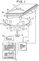
- Figure 1 illustrates the configuration of the apparatus for reading a luminescence pattern relating to a first embodiment of the present invention.
- item 1 is a stage on which the sample is placed
- item 2 is a photoreceptor disk
- item 3 is a rotary motor including a support for the photo-receptor disk
- item 4 is a condenser unit
- item 5 is an optical guide part
- item 6 is a photomultiplier of the photoelectric converter
- item 7 is an electrophoresis gel of the sample to be read
- item 8 is a transport mechanism that transports the stage
- item 9 is a read scanning control unit
- item 10 is an analog-to-digital (A/D) converter
- item 11 is a data processor
- item 12 is a data processing unit which performs a coordinate transformation process
- item 13 is an image memory unit.
- the action of the apparatus for reading a luminescence pattern having this sort of configuration is summarized in the following.
- the electrophoresis gel 7 that is to be read consists of a polyacrylamide gel 7a sandwiched between the glass supporting plates 7b and 7c.
- Readings can also be made by hybridizing the sample with a probe labeled with a luminescent substrate in a biochip (the chambers of a minute chip partitioned into a plurality of boxes, in which the probe, the sample and the like are reacted together), thereby allowing the target DNA to be detected from the resulting luminescence pattern, in which case the biochip that is to be read is mounted on the stage 1 in the same way as in the case of a gel, and the apparatus is instructed to read the luminescence pattern.
- a biochip the chambers of a minute chip partitioned into a plurality of boxes, in which the probe, the sample and the like are reacted together
- the electrophoresis gel 7 of the sample to be read is mounted on the stage 1, and an instruction to begin the reading operation is issued from a console panel (not illustrated), whereupon a start signal for controlling the luminescence pattern reading is output, the read scanning control unit 9 controls the transport mechanism 8 and the rotary motor 3, and the reading scan begins.
- the secondary scanning in the Y direction is performed by the transport mechanism 8, which transports the stage 1 in a straight line in the Y direction
- the primary scanning in the X direction is performed by the rotary motor 3 turning the photoreceptor disk 2, whereby the condenser unit 4 provided on this photoreceptor disk 2 moves rotationally over the arc-shaped scan lines.
- the photoreceptor disk 2 installed in the lower part of the stage 1 rotates, and according to the rotational motion of the condenser unit 4 provided on this photoreceptor disk 2, the photoreception position of the light from the reading surface of the luminescence pattern of the electrophoresis gel 7 of the sample is scanned by the rotating plate, and the light of the luminescence pattern is condensed.
- the read scanning control unit 9 controlling the rotary motor 3 and the transport mechanism 8 controls the read scanning position by driving the photoreceptor disk 2 and the stage 1, at which time, the reading position at which the condenser unit 4 condenses the light from the reading surface of the luminescence pattern, is generated as a read scanning position signal in polar coordinates by the read scanning control unit 9 according to the control of the rotary motor 3 and the transport mechanism 8. Accordingly, in data processor 11, data processing unit 12 uses this read scanning position signal to store the corresponding position in the image memory 13.
- the data processing unit 12 which performs a coordinate transformation process in the data processor 11 transforms the positions of the arc-shaped scan lines of the photoreceptor disk 2 into a coordinate system of rectangular coordinates.
- the condenser unit 4 - which constitutes a photoreceptor window - scans and reads the luminescence pattern by moving along an arc-shaped path.
- the light of the luminescence pattern condensed by the condenser unit 4 of the photoreceptor disk 2 is, as mentioned below, guided by the optical guide part 5 configured from a combination of a plurality of mirrors, and introduced into the photoreceptor entrance of the photomultiplier 6 of the photoelectric converter 10.
- the photomultiplier 6 receives light from the luminescence pattern guided by the optical guide part 5, transforms it into an electrical signal, converts it into a digital signal with the analog-to-digital (A/D) converter 10, and supplies it to the data processor 11.
- the data processor 11 is equipped with the data processing unit 12 which performs a coordinate transformation process and the image memory 13, and when the luminescence pattern is stored in the image memory 13, the data processing unit 12 obtains the scanning position signal from the controller, and from this scanning position signal it converts the polar coordinate system of the positions scanned by the photoreceptor disk 2 into a rectangular coordinate system and stores them in the image memory 13. In this way it is possible to obtain a luminescence pattern no different from that obtained by scanning with a straight-line scanning mechanism.
- Figure 2 illustrates the optical path whereby the luminescence pattern is detected with a condenser unit and an optical guide part.
- item 2 is a photo-receptor disk
- item 4 is a condenser unit
- item 5 is an optical guide part
- item 6 is a photomultiplier
- item 7 is an electrophoresis gel of the sample to be read
- item 21 is a first lens
- item 22 is a wavelength-selective filter
- item 23 is a second lens
- item 24 is a pinhole
- item 25 is a third lens
- item 26 is a first planar mirror
- item 27 is a second planar mirror.
- the operation will be described in the following with reference to Figure 2.
- the light emitted from the electrophoresis gel 7 of the sample persists for at least 10 or 20 minutes because it is produced by chemiluminescence, and so the luminescence pattern emitted from the sample is scanned and read in during this period and stored in corresponding positions in the image memory.
- This read scanning is performed by making a plurality of scans over the entire luminescence pattern, during which the amounts of light in each pixel of the luminescence pattern are accumulated. That is, once a single scan over the entire luminescence pattern has been completed, the stage 1 is returned to its starting position, and the read scanning control unit 9 controls the rotary motor 3 and the transport mechanism 8 so as to perform the scan again. These operations are performed repeatedly. As a result, the amounts of light in each pixel of the entire luminescence pattern are accumulated together, and an image is built up in the pixels corresponding to the luminescence pattern.
- the condenser unit 4 uses a hole part provided in the photoreceptor disk 2 as a pinhole, and is provided with a housing part in which the lenses and the like are provided across both sides of the rotating plate.
- the lens of the photoreceptor part is installed below the electrophoresis gel 7 of the luminescent sample sandwiched between the glass plates so as to be situated close to it.
- the optical system of the condenser unit 4 consists of the first lens 21, the wavelength-selective filter 22, the second lens 23, the pinhole 24 which is the hole part provided in the rotary disk 2, and the third lens 25, and the optical system of the optical guide part 5 consists of the first planar mirror 26 and the second planar mirror 27.
- the target wavelength is selected by passing through the wavelength-selective filter 22.
- the light is then condensed by the second lens 23, and the background noise component of the received optical components is eliminated by passing through the pinhole 24, which is the hole part in the photoreceptor disk 2 disposed at the focal point of the second lens 23. That is, the light that has passed through the pinhole 24 corresponds only to the light from a single point on the sample (electrophoresis gel 7).
- This light is collimated again by the third lens 25 and redirected by the first planar mirror 26 and the second planar mirror 27 to guide its optical path toward the photomultiplier 6, where it is sensed.
- Figure 3a and 3b illustrate the positional relationship of the plurality of condenser units provided on the photo-receptor disk configured so as to read a multi-color luminescence pattern;
- Figure 3a is a plan view of the photoreceptor disk and
- Figure 3b is a side view in partial cross section.
- three condenser units 41, 42 and 43 are provided on the photoreceptor disk 2 at positions on the circumference of the same circle and separated from each other by rotational angles of 120 degrees.
- These three condenser units 41, 42 and 43 each have the same configuration of a pinhole, lenses and the like, but their wavelength-selective filters 22 each have different selection wavelengths, and they are configured to selectively receive light of different colors. In this way, they can scan each color of a multi-color luminescence pattern by condensing light of different colors from the luminescence pattern along the same arc-shaped scan lines.
- the optical guide part 5 is provided at the rotational center position of the photoreceptor disk 2, and the light of the luminescence pattern that has been condensed by the lenses and pinholes of each condenser unit 41, 42 and 43 is sent toward the optical guide part 5 provided at the rotational center position of the photoreceptor disk 2 by a planar mirror 26 provided in the lower part of each condenser unit.
- the optical guide part 5 is provided with the planar mirrors 27 so that it can redirect the light sent in from each of the condenser units 41, 42 and 43 toward the photomultiplier 6. That is, the planar mirrors 27 are fixed back-to-back opposite each of the condenser units 41, 42 and 43 to form a triangular shape.
- This optical guide part 5 is fixed to the photoreceptor disk 2 and rotates in unison with the photoreceptor disk 2, and outputs the light from the condenser units 41, 42 and 43 to the photomultiplier 6, which is fixed to the housing of the luminescence pattern reading apparatus (not illustrated) and does not rotate.
- This photomultiplier 6 is provided at the center of rotation of the photoreceptor disk 2, and its relative positional relationship to the optical guide part 5 does not change. It is noted that a configuration is adopted in which a shutter mechanism (not illustrated) is provided in the optical paths of each of the condenser units, so that when the condenser unit 41 is positioned at the scan line that is currently being read, the light from the condenser units (42 and 43) that are not positioned at a read scanning line does not arrive at the photoreceptor entrance of the photomultiplier 6.
- the shutter mechanism is provided with, for example, a mask that covers two thirds of the optical guide part 5 on the left-hand side that is not related to the region over which the reading scan lines move. It is also configured so that the photoreceptor entrance of the photomultiplier 6 is provided slightly shifted from the center of rotation, so that only light from the condenser unit in the region over which the reading scan lines move is guided to the photoreceptor entrance.
- the gel 7a of the sample is sandwiched between the glass supporting plates 7b and 7c, and light from the luminescence pattern of the electrophoresis gel 7 of said luminescent sample at the respective positions of the condenser units 41, 42 and 43 provided on the rotating photoreceptor disk 2 is condensed and sent to the optical guide part 5, whereupon, while the photoreceptor disk 2 and the optical guide part 5 rotate, the light from the condenser units 41, 42 and 43 is sent out to the same position at the photoreceptor entrance of the fixed photomultiplier 6.
- the photomultiplier 6 outputs an electrical signal according to the amount of light condensed from the photoreceptor entrance.
- FIG. 4 is a block diagram showing the configuration of the electrical system of the luminescence pattern reading apparatus.
- the configuration of the electrical system comprises, a microprocessor (CPU) 150 for executing the control processing of the luminescence pattern reading apparatus, a read-only memory (ROM) 152 for storing the control software program, a random access memory (RAM) 151 which provides a memory area for temporary data storage, an area used for image memory, and a memory area for other forms of data processing, a photoreceptor disk rotation controller 154, a stage transport controller 155, an A/D converter 157 for analog-to-digital conversion of the analog signal made by converting the received light into an electrical signal into digital data, a shading correction circuit 158 for correcting the fixed offset in the optical measurement system of the photoreceptor paths of the condenser units, and a SCSI controller 153 which controls the interface with an external data processor 159.
- CPU microprocessor
- ROM read-only memory
- RAM random access memory
- A/D converter 157 for
- the overall electrical system operates as follows: as the power source is connected, each part of the apparatus is first initialized, and when the initialization process has finished, the reading of the sample's luminescence pattern is controlled.
- details of the initialization process might include processes such as, for example, checking read-only memory (ROM) 152 and random access memory (RAM) 151, checking the rotary operation of the photoreceptor disk, checking the stage transport operation, and initializing the interface unit of the SCSI controller that controls the interface.
- Figure 5 describes a variant wherein the optical guide part is configured from an optical fiber.
- the function of the optical guide part is to send light from the condenser unit to the photo-multiplier, and so instead of the configuration of two planar mirrors in the abovementioned embodiment it can be configured to use an optical fiber to guide the condensed light directly to the photomultiplier.
- an optical fiber 51 is disposed with its light-entrance end 52 at the light-exiting end from the lens 25 of the condenser unit 4, and with its light-exiting end 53 disposed at the photoreceptor entrance of the photomultiplier 6.
- the optical fiber 51 of the optical guide part is fixed to the photoreceptor disk 2, and rotates together with the photoreceptor disk 2.
- the light-exiting end of the optical fiber 51 is disposed so as to be positioned on the axis of the photoreceptor disk 2 at the rotational center thereof. The light-exiting ending from the fiber thereby reaches the photoreceptor entrance of the fixed photomultiplier 6.
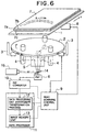
- Figure 6 illustrates the configuration of the apparatus for reading a luminescence pattern relating to a second embodiment of the present invention.
- item 1 is a stage on which the sample is placed
- item 2 is a photoreceptor disk
- item 3 is a rotary motor including a support for the photoreceptor disk
- item 4 is a condenser unit
- item 5 is an optical guide part
- item 6 is a photomultiplier of the photoelectric converter
- item 7 is an electrophoresis gel of the sample to be read
- item 8 is a transport mechanism that transports the stage
- item 9 is a read scanning control unit
- item 10 is an analog-to-digital (A/D) converter
- item 11 is a data processor
- item 12 is a data processing unit which performs a coordinate transformation process
- item 13 is an image memory unit
- item 14 is a dichroic mirror
- item 15 is a laser light source.
- the laser light source 15 and the dichroic mirror 14 are provided as elements for shining laser light onto the electrophoresis gel of a sample tagged with a fluorescent substrate.
- excitation light is irradiated onto the electrophoresis gel of a sample labeled with a fluorescent substrate, whereby the fluorescent substrate in the sample emits light by fluorescence, which is then read.
- the reading is done by introducing excitation light from the laser light source 15 into the optical path via the dichroic mirror 14.
- the electrophoresis gel 7 that is to be read is mounted on the stage 1, and the apparatus is instructed to read the luminescence pattern.
- the electrophoresis gel 7 that is to be read consists of a polyacrylamide gel 7a sandwiched between glass supporting plates 7b and 7c. Readings are also made in the same way when a biochip is used for the sample.
- the electrophoresis gel 7 of the sample to be read is mounted on the stage 1, and an instruction to begin the reading operation is issued from a console panel (not illustrated), whereupon a start signal for controlling the luminescence pattern reading is output, the read scanning control unit 9 controls the transport mechanism 8 and the rotary motor 3, and the reading scan begins.
- the laser light source 15 is turned on and emits excitation light.
- the excitation light has a relatively large beam width, and excitation light with a large beam width is irradiated over the entire surface of the dichroic mirror 14.
- the excitation light is reflected by the dichroic mirror 14, passes through the optical guide part 5 and the condenser unit 4, and irradiates on the part of the electrophoresis gel 7 that is being read.
- the secondary scanning in the Y direction is performed by the transport mechanism 8, which transports the stage 1 in a straight line in the Y direction
- the primary scanning in the X direction is performed by the rotary motor 3 turning the photoreceptor disk 2, whereby the condenser unit 4 provided on this photoreceptor disk 2 moves rotationally over the arc-shaped scan lines.
- the excitation light for exciting the luminescent substrate in the sample is emitted from laser light source 15, this light is reflected by the dichroic mirror 14, and the reflected light passes through the optical guide part 5, through the lenses of the condenser unit 4 provided in the photoreceptor disk 2, and irradiates from below onto the part of the sample electrophoresis gel 7 that is to be read. Accordingly, this excitation light is scanned over the electrophoresis gel 7 of the sample in conjunction with the rotation of the photoreceptor disk 2.
- the photoreceptor disk 2 is installed in the lower part of the stage 1, and the rotation of this photoreceptor disk 2 causes the condenser unit 4 provided on the photoreceptor disk 2 to move rotationally, whereby the photoreception position of the light from the reading surface of the electrophoresis gel 7 of the sample is scanned along arc-shaped lines. While this scanning takes place, the fluorescent emitted light is condensed.
- the read scanning control unit 9 controlling the the rotary motor 3 and the transport mechanism 8 controls the read scanning position by driving the photoreceptor disk 2 and the stage 1, at which time the reading position at which the condenser unit 4 condenses the light from the reading surface of the electrophoresis gel 7, which emits fluorescent light, is generated as a read scanning position signal in polar coordinates by the read scanning control unit 9 according to the control of the rotary motor 3 and the transport mechanism 8. Accordingly, in the data processor 11, the data processing unit 12 uses this read scanning position signal to store the corresponding position in the image memory 13.
- the data processing unit 12 which performs a coordinate transformation process in the data processor 11 transforms the positions of the arc-shaped scan lines of the photoreceptor disk 2 into a coordinate system of rectangular coordinates.
- the condenser unit 4 - which constitutes the photoreceptor window - irradiates the excitation light onto the sample, and scans and reads the fluorescent light pattern by moving along an arc-shaped path.
- the light of the fluorescent light pattern condensed by the condenser unit 4 of the photoreceptor disk 2 is guided by the optical guide part 5 and reaches the dichroic mirror 14.
- the dichroic mirror 14 the light from the fluorescent light pattern is allowed to pass straight through, and so this light is introduced into the photoreceptor entrance of the photomultiplier 6 of the photoelectric converter.
- the photomultiplier 6 receives the light from the fluorescent light pattern that has been introduced into the photoreceptor entrance thereof, and transforms it into an electrical signal. This is then converted into a digital signal by the analog-to-digital (A/D) converter 10, and supplied to the data processor 11.
- A/D analog-to-digital
- the apparatus for reading a luminescence pattern according to the second embodiment differs from the abovementioned first embodiment in that, when reading the electrophoresis gel 7 of a sample labeled with a fluorescent substrate, the laser light source 15 is turned on to make it emit laser light, which is used as excitation light by introducing it into the optical path via the dichroic mirror 14 to make it irradiate on the part of the electrophoresis gel 7 of the sample that is being read.
- the light emitted from the laser light source 15 is introduced into the optical path by reflecting it with the dichroic mirror 14, passes through the optical guide part 5, and is guided to the part of the electrophoresis gel 7 of the sample that is being read.
- the fluorescent light emitted from the sample that has been excited by the excitation light from the laser light source 15 is dealt with in the same way as in the luminescent pattern reading of the first embodiment mentioned above; that is, it passes through the optical guide part 5, is introduced into the photomultiplier via the dichroic mirror 14, and is finally subjected to suitable processing in the data processor.
- the dichroic mirror 14 used here is one that reflects light at the wavelength emitted from the laser light source 15, and allows the fluorescent light from the sample to pass through.
- the luminescent pattern is read through the dichroic mirror 14, and so although the amount of light that can be detected is reduced, it is otherwise the same as the case of the first embodiment.
- the data processor 11 is equipped with the data processing unit 12 which performs a coordinate transformation process and the image memory 13, and when the luminescence pattern is stored in the image memory 13, the data processing unit 12 obtains the scanning position signal from the controller, and from this scanning position signal it converts the polar coordinate system of the positions scanned by the photoreceptor disk into a rectangular coordinate system and stores them in the image memory 13. In this way it is possible to obtain a luminescence pattern no different from that obtained by scanning with a straight-line scanning mechanism.
- Figure 7 illustrates the optical path whereby the luminescence pattern is detected with a condenser unit and an optical guide part according to the second embodiment.
- item 2 is a photoreceptor disk
- item 4 is a condenser unit
- item 5 is an optical guide part
- item 6 is a photomultiplier
- item 7 is an electrophoresis gel of the sample to be read
- item 14 is a dichroic mirror
- item 15 is a laser light source
- item 21 is a first lens
- item 22 is a wavelength-selective filter
- item 23 is a second lens
- item 24 is a pinhole
- item 25 is a third lens
- item 26 is a first planar mirror
- item 27 is a second planar mirror.
- the excitation light source is scanned over and irradiated at the sample by the rotation of the photoreceptor disk 2, and the light of the fluorescent light pattern thereby emitted from the electrophoresis gel 7 of the sample is scanned and read, and stored at a position in the image memory corresponding to this scanning position.
- This read scanning is also performed by making a plurality of scans over the entire fluorescent light pattern, during which the amounts of light in each pixel of the fluorescent light pattern are accumulated. That is, once a single scan over the entire fluorescent light pattern has been completed, the stage 1 is returned to its starting position, and the read scanning control unit 9 controls the rotary motor 3 and the transport mechanism 8 so as to perform the scan again. These operations are performed repeatedly. As a result, the amounts of light in each pixel of the entire fluorescent light pattern - which is weakly luminescent - are accumulated together, and an image is built up in the pixels corresponding to the fluorescent light pattern.
- the condenser unit 4 uses a hole part provided in the photoreceptor disk 2 as a pinhole, and is provided with a housing part in which the lenses and the like are provided across both sides of the rotating plate.
- the lens of the photoreceptor part is installed in the lower part thereof so as to adjoin the electrophoresis gel 7 of the luminescent sample sandwiched between the glass plates.
- the optical system of the condenser unit 4 consists of a first lens 21, a wavelength-selective filter 22, a second lens 23, a pinhole 24 which is the hole part provided in the rotary disk 2, and a third lens 25, and the optical path of the optical system of optical guide part 5 consists of a first planar mirror 26 and a second planar mirror 27.
- the laser light source 15 and the dichroic mirror 14 is provided in the optical path between the optical guide part 5 and the photomultiplier 6.
- the excitation light from the laser light source 15 is introduced into the optical path via the dichroic mirror 14, and fluorescent light is emitted from the electro-phoresis gel 7 of the sample when this excitation light is irradiated on it.
- the target wavelength is selected by passing through the wavelengths elective filter 22.
- the light is then condensed by the second lens 23, and the background noise component of the received optical components is eliminated by passing through the pinhole 24, which is the hole part in the photoreceptor disk 2 disposed at the focal point of the second lens 23. That is, the light that has passed through the pinhole 24 corresponds only to the light from a single point on the sample (electrophoresis gel 7).
- This light is collimated again by the third lens 25 and redirected by the first planar mirror 26 and the second planar mirror 27, and passes through the dichroic mirror 14, whereby its optical path is guided toward the photomultiplier 6, where it is sensed.
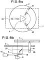
- Figure 8a and 8b illustrate the positional relationship of the plurality of condenser units provided on a photoreceptor disk configured so as to read a multi-color luminescence pattern in apparatus for reading a luminescence pattern according to the second embodiment;
- Figure 8a is a plan view of the photoreceptor disk and
- Figure 8b is a side view in partial cross section.
- three condenser units 41, 42 and 43 are provided on the photoreceptor disk 2 at positions on the circumference of the same circle and separated from each other by rotational angles of 120 degrees.
- These three condenser units 41, 42 and 43 each have the same configuration of a pinhole, lenses and the like, but their wavelength-selective filters 22 each have different selection wavelengths, and they are configured to selectively receive light of different colors. In this way, they can scan each color of a multi-color luminescence pattern by condensing light of different colors from the luminescence pattern along the same arc-shaped scan lines.
- An optical guide part 5 is provided at the rotational center position of the photoreceptor disk 2, and the light of the luminescence pattern that has been condensed by the lenses and pinholes of each condenser unit 41, 42 and 43 is sent toward the optical guide part 5 provided at the rotational center position of the photoreceptor disk 2 by a planar mirror 26 provided in the lower part of each condenser unit.
- the optical guide part 5 is provided with planar mirrors 27 so that it can redirect the light sent in from each of the condenser units 41, 42 and 43 toward the photomultiplier 6, and these planar mirrors 27 are fixed back-to-back opposite each of the condenser units 41, 42 and 43 to form a triangular shape.
- the optical guide part 5 is fixed to the photoreceptor disk 2 and rotates in unison with the photoreceptor disk 2, and outputs the light from the condenser units 41, 42 and 43 to the photomultiplier 6, which is fixed to the housing of the luminescence pattern reading apparatus (not illustrated) and does not rotate.
- the photomultiplier 6 is provided at the center of rotation of the photoreceptor disk 2, and its relative positional relationship to the optical guide part 5 does not change. It is noted that a configuration is adopted in which a shutter mechanism (not illustrated) is provided in the optical paths of each of the condenser units, so that when the condenser unit 41 is positioned at the scan line that is currently being read, the light from the condenser units (42 and 43) that are not positioned at a read scanning line does not arrive at the photoreceptor entrance of the photomultiplier 6.
- the shutter mechanism is provided with, for example, a mask that covers two thirds of the optical guide part 5 - which rotates in unison with the photoreceptor disk 2 - on the left-hand side that is not related to the region over which the reading scan lines move. It is also configured so that the photoreceptor entrance of the photomultiplier 6 is provided slightly shifted from the center of rotation, and so that a mask mechanism or shutter mechanism is provided whereby only light from the condenser unit in the region over which the reading scan lines move is guided to the photoreceptor entrance.
- the gel 7a of the sample is sandwiched between the glass supporting plates 7b and 7c, and fluorescent light from the luminescence pattern of electrophoresis gel 7 of said luminescent sample that is emitted when the excitation light is irradiated on it is condensed at the respective positions of the condenser units 41, 42 and 43 provided on the rotating photoreceptor disk 2 and sent to the optical guide part 5, whereupon, while the photoreceptor disk 2 and the optical guide part 5 rotate, the light from the condenser units 41, 42 and 43 is sent out to the same position at the photoreceptor entrance of the fixed photomultiplier 6 via the fixed dichroic mirror 14.
- the photomultiplier 6 outputs an electrical signal according to the amount of light condensed from the photoreceptor entrance.
- Figure 9 is a block diagram showing the configuration of the electrical system of the luminescence pattern reading apparatus according to the second embodiment of the present invention.
- the configuration of the electrical system of the second embodiment is further provided with a light source controller 160 which controls the use of the laser light source according to whether reading is to be performed on a luminescence pattern using the fluorescence method or the chemiluminescence method.
- a microprocessor (CPU) 150 for executing the control processing of the luminescence pattern reading apparatus
- ROM read-only memory
- RAM random access memory
- a photoreceptor disk rotation controller 154 for executing the control processing of the luminescence pattern reading apparatus
- a stage transport controller 155 which provides a memory area for temporary data storage, an area used for image memory, and a memory area for other forms of data processing
- a photoreceptor disk rotation controller 154 for a stage transport controller 155
- an A/D converter 157 for analog-to-digital conversion of the analog signal made by converting the received light into an electrical signal into digital data
- a shading correction circuit 158 for correcting the fixed offset in the optical measurement system of the photoreceptor paths of the condenser units
- a light source controller 160 which controls the use of the laser light source according to whether reading is to be performed on a luminescence pattern using the fluorescence method or the chemiluminescence method
- SCSI controller 153 which controls the interface with an external
- the overall electrical system operates as follows: as the power source is connected, each part of the apparatus is first initialized, and when the initialization process has finished, the reading of the sample's luminescence pattern is controlled.
- details of the initialization process might include processes such as, for example, checking read-only memory (ROM) 152 and random access memory (RAM) 151, checking the rotary operation of the photoreceptor disk, checking the stage transport operation, checking light source controller 160 which turns the laser light source on and off, and initializing the interface unit of the SCSI controller that controls the interface.
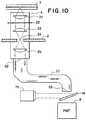
- Figure 10 is a first figure illustrating a variant wherein the optical guide part is configured from an optical fiber.
- the function of the optical guide part is to send light from the condenser unit to the photomultiplier, and so instead of the configuration of two planar mirrors in the abovementioned embodiment it can be configured to use an optical fiber to guide the condensed light directly to the dichroic mirror 14, and after it has passed through the dichroic mirror 14, it is sensed by the photomultiplier 6.
- the optical fiber 51 is disposed with its light-entrance end 52 at the light-exiting end from lens 25 of the condenser unit 4, and with its light-exiting end 53 disposed in front of the dichroic mirror 14 so that the light that has passed through the dichroic mirror 14 is introduced into the photoreceptor entrance of the photomultiplier 6.
- the optical fiber 51 corresponding to the optical guide part is fixed to the photoreceptor disk 2, and rotates together with photoreceptor disk 2.
- the light-exiting end of the optical fiber 51 is disposed so as to be positioned on the axis of the photoreceptor disk 2 at the rotational center thereof. The light-exiting ending from the fiber thereby reaches the photoreceptor entrance of the fixed photomultiplier 6.
- Figure 11a and 11b are a second figure illustrating a second variant wherein the optical guide part is configured from an optical fiber.
- the light-exiting ends of the optical fibers from a plurality of condenser units adapted for multi-color reading are gathered together and disposed toward the dichroic mirror 14, and the excitation light of broadened width from the laser light source 15 is received from the entire reflecting surface of the dichroic mirror 14.
- the appearance is as shown in Figure 11b where, as the light-exiting ends of the plurality of optical fibers rotate, the excitation light of broadened width from the laser light source 15 is introduced, and the fluorescence light from the sample thereby excited is sensed.
- the sensed fluorescence light passes through the dichroic mirror 14 and is guided into the photoreceptor entrance of the photomultiplier 6.
- the apparatus for reading a luminescence pattern when reading a luminescence pattern from a planar sample that emits a faint light, it is possible to use a photosensor to perform the reading at low cost, with high sensitivity and at high speed without using a highly sensitive two-dimensional sensor such as a cooled CCD as has been used hitherto. It is also possible to provide apparatus for reading a fluorescence pattern that is able to read both fluorescent light and chemiluminescent light.
Applications Claiming Priority (3)
| Application Number | Priority Date | Filing Date | Title |
|---|---|---|---|
| JP262953/97 | 1997-09-11 | ||
| JP26295397 | 1997-09-11 | ||
| JP26295397 | 1997-09-11 |
Publications (2)
| Publication Number | Publication Date |
|---|---|
| EP0902280A2 true EP0902280A2 (fr) | 1999-03-17 |
| EP0902280A3 EP0902280A3 (fr) | 2000-04-12 |
Family
ID=17382850
Family Applications (1)
| Application Number | Title | Priority Date | Filing Date |
|---|---|---|---|
| EP98107710A Withdrawn EP0902280A3 (fr) | 1997-09-11 | 1998-04-28 | Dispositif de lecture pour la luminescence d'un échantillon |
Country Status (2)
| Country | Link |
|---|---|
| US (1) | US5991030A (fr) |
| EP (1) | EP0902280A3 (fr) |
Cited By (3)
| Publication number | Priority date | Publication date | Assignee | Title |
|---|---|---|---|---|
| WO2001001115A1 (fr) * | 1999-06-29 | 2001-01-04 | Packard Instrument Company, Inc. | Analyse par imagerie pour microechantillons |
| CN103309357A (zh) * | 2013-06-25 | 2013-09-18 | 西安康柏自动化工程有限责任公司 | 一种二自由度激光扫描方法及中空式数控云台 |
| CN105675574A (zh) * | 2016-03-17 | 2016-06-15 | 苏州天隆生物科技有限公司 | 用于实时荧光定量pcr的多荧光通道检测系统 |
Families Citing this family (15)
| Publication number | Priority date | Publication date | Assignee | Title |
|---|---|---|---|---|
| US20030206114A1 (en) * | 1998-08-04 | 2003-11-06 | Leping Li | Interface device for sti/bpsg EPD and real time control |
| US6211526B1 (en) * | 1998-09-30 | 2001-04-03 | The United States Of America As Represented By The Secretary Of The Navy | Marking of materials using luminescent and optically stimulable glasses |
| JP3678397B2 (ja) * | 1998-12-15 | 2005-08-03 | 富士写真フイルム株式会社 | 撮影システム |
| US6320196B1 (en) * | 1999-01-28 | 2001-11-20 | Agilent Technologies, Inc. | Multichannel high dynamic range scanner |
| US6215894B1 (en) * | 1999-02-26 | 2001-04-10 | General Scanning, Incorporated | Automatic imaging and analysis of microarray biochips |
| US6596483B1 (en) * | 1999-11-12 | 2003-07-22 | Motorola, Inc. | System and method for detecting molecules using an active pixel sensor |
| US6407395B1 (en) * | 2000-02-29 | 2002-06-18 | The University Of Chicago | Portable biochip scanner device |
| CN1311436A (zh) * | 2000-03-01 | 2001-09-05 | 上海和泰光电科技有限公司 | 旋转平台上的生物芯片荧光图象的读取 |
| US6403970B1 (en) * | 2000-12-05 | 2002-06-11 | Industrial Technology Research Institute | Matrix biochip sensing system |
| US6552794B2 (en) * | 2001-04-04 | 2003-04-22 | Applied Spectral Imaging Ltd. | Optical detection method for improved sensitivity |
| US6793790B1 (en) | 2001-06-06 | 2004-09-21 | The Regents Of The University Of California | Sample collection system for gel electrophoresis |
| KR100489264B1 (ko) * | 2002-07-22 | 2005-05-17 | 주식회사 옵트론-텍 | 형광검출장치 및 그 제조방법 |
| US20060249652A1 (en) * | 2005-05-03 | 2006-11-09 | Kyle Schleifer | Methods and systems for pixilation processing of precision, high-speed scanning |
| CN102175612B (zh) * | 2011-01-18 | 2012-12-26 | 河北工业大学 | 一种多路光电检测装置 |
| CA2859475C (fr) | 2011-12-16 | 2015-07-07 | Li-Cor, Inc. | Scanner d'imagerie a luminescence |
Citations (4)
| Publication number | Priority date | Publication date | Assignee | Title |
|---|---|---|---|---|
| EP0488422A2 (fr) * | 1990-11-30 | 1992-06-03 | Hitachi Software Engineering Co., Ltd. | Appareil de lecture des images d'électrophorèse en plusieurs couleurs |
| US5246866A (en) * | 1987-12-23 | 1993-09-21 | Hitachi Software Engineering Co., Ltd. | Method for transcription of a DNA sequence |
| US5538613A (en) * | 1993-10-26 | 1996-07-23 | Genesys Technologies, Inc. | Electrophoresis analyzer |
| US5614073A (en) * | 1995-03-13 | 1997-03-25 | Board Of Trustees Of The University Of Arkansas | Method and apparatus for detection of underivatized amines and amino acids utilizing end column addition of Ru(bpy)32+ |
Family Cites Families (3)
| Publication number | Priority date | Publication date | Assignee | Title |
|---|---|---|---|---|
| JPH083481B2 (ja) * | 1989-06-07 | 1996-01-17 | 日立ソフトウェアエンジニアリング株式会社 | 蛍光式電気泳動パターン読み取り装置 |
| US5736410A (en) * | 1992-09-14 | 1998-04-07 | Sri International | Up-converting reporters for biological and other assays using laser excitation techniques |
| JP3520565B2 (ja) * | 1994-06-21 | 2004-04-19 | 日本油脂Basfコーティングス株式会社 | 粉体塗料用反応性流動調整剤および粉体塗料 |
-
1998
- 1998-04-28 EP EP98107710A patent/EP0902280A3/fr not_active Withdrawn
- 1998-04-28 US US09/066,875 patent/US5991030A/en not_active Expired - Lifetime
Patent Citations (4)
| Publication number | Priority date | Publication date | Assignee | Title |
|---|---|---|---|---|
| US5246866A (en) * | 1987-12-23 | 1993-09-21 | Hitachi Software Engineering Co., Ltd. | Method for transcription of a DNA sequence |
| EP0488422A2 (fr) * | 1990-11-30 | 1992-06-03 | Hitachi Software Engineering Co., Ltd. | Appareil de lecture des images d'électrophorèse en plusieurs couleurs |
| US5538613A (en) * | 1993-10-26 | 1996-07-23 | Genesys Technologies, Inc. | Electrophoresis analyzer |
| US5614073A (en) * | 1995-03-13 | 1997-03-25 | Board Of Trustees Of The University Of Arkansas | Method and apparatus for detection of underivatized amines and amino acids utilizing end column addition of Ru(bpy)32+ |
Cited By (7)
| Publication number | Priority date | Publication date | Assignee | Title |
|---|---|---|---|---|
| WO2001001115A1 (fr) * | 1999-06-29 | 2001-01-04 | Packard Instrument Company, Inc. | Analyse par imagerie pour microechantillons |
| EP1515135A3 (fr) * | 1999-06-29 | 2005-07-20 | Packard Instrument Company, Inc. | Analyse par imagerie pour microechantillons |
| US6969835B1 (en) | 1999-06-29 | 2005-11-29 | Packard Instrument Company Inc. | Imaging assay analysis for microsamples |
| CN103309357A (zh) * | 2013-06-25 | 2013-09-18 | 西安康柏自动化工程有限责任公司 | 一种二自由度激光扫描方法及中空式数控云台 |
| CN103309357B (zh) * | 2013-06-25 | 2016-03-02 | 西安康柏自动化工程有限责任公司 | 一种二自由度激光扫描方法及中空式数控云台 |
| CN105675574A (zh) * | 2016-03-17 | 2016-06-15 | 苏州天隆生物科技有限公司 | 用于实时荧光定量pcr的多荧光通道检测系统 |
| CN105675574B (zh) * | 2016-03-17 | 2018-08-10 | 西安天隆科技有限公司 | 用于实时荧光定量pcr的多荧光通道检测系统 |
Also Published As
| Publication number | Publication date |
|---|---|
| US5991030A (en) | 1999-11-23 |
| EP0902280A3 (fr) | 2000-04-12 |
Similar Documents
| Publication | Publication Date | Title |
|---|---|---|
| US5991030A (en) | Apparatus for reading a luminescence pattern of a sample | |
| US6867851B2 (en) | Scanning of biological samples | |
| US5585639A (en) | Optical scanning apparatus | |
| US7145645B2 (en) | Imaging of biological samples using electronic light detector | |
| EP0644419B1 (fr) | Appareil à balayage | |
| US7323681B1 (en) | Image enhancement by sub-pixel imaging | |
| US7199357B1 (en) | Image enhancement by sub-pixel imaging | |
| EP1983331A2 (fr) | Lecteur de biopuce et système de lecture de données d'image en fonction d'échantillons sur une biopuce | |
| US7354389B2 (en) | Microarray detector and methods | |
| JP2001516036A (ja) | 多パラメータスキャナー | |
| EP1356266A2 (fr) | Balayage optique haute performance d'un substrat | |
| US6630680B2 (en) | Scanner having confocal optical system, method for producing focus position data of confocal optical system of scanner having confocal optical system and method for producing digital data of scanner having confocal optical system | |
| WO2002093144A1 (fr) | Imagerie d'echantillons biologiques au moyen d'un photodetecteur electronique | |
| JP2008507694A (ja) | 光学診断装置のための読み取りヘッド | |
| JP2001311690A (ja) | バイオチップ読取装置及び電気泳動装置 | |
| JP3387783B2 (ja) | スキャナ装置 | |
| JP3180072B2 (ja) | 発光パターン読み取り装置 | |
| JP2002296509A (ja) | 共焦点光学系を備えたスキャナ、共焦点光学系を備えたスキャナの共焦点光学系のフォーカス位置データの生成方法および共焦点光学系を備えたスキャナにおけるディジタルデータの生成方法 | |
| US6919201B2 (en) | Biochip measuring method and measuring equipment | |
| US6759672B2 (en) | System for and method of reading out storage phosphor screen using pulsed semiconductor light source array | |
| WO2001057501A1 (fr) | Lecteur de jeux ordonnes de microechantillons ameliore | |
| CA3125594A1 (fr) | Eclairage de raie laser faisant appel a des sources laser monomode et multimode combinees | |
| JP3695631B2 (ja) | 電気泳動装置 | |
| JP2000131237A (ja) | マイクロアレイチップの読取方法および読取装置 | |
| US11543639B2 (en) | Macro-micro telecentric scanning systems and methods |
Legal Events
| Date | Code | Title | Description |
|---|---|---|---|
| PUAI | Public reference made under article 153(3) epc to a published international application that has entered the european phase |
Free format text: ORIGINAL CODE: 0009012 |
|
| AK | Designated contracting states |
Kind code of ref document: A2 Designated state(s): DE FR GB |
|
| AX | Request for extension of the european patent |
Free format text: AL;LT;LV;MK;RO;SI |
|
| PUAL | Search report despatched |
Free format text: ORIGINAL CODE: 0009013 |
|
| AK | Designated contracting states |
Kind code of ref document: A3 Designated state(s): AT BE CH CY DE DK ES FI FR GB GR IE IT LI LU MC NL PT SE |
|
| AX | Request for extension of the european patent |
Free format text: AL;LT;LV;MK;RO;SI |
|
| 17P | Request for examination filed |
Effective date: 20000802 |
|
| AKX | Designation fees paid |
Free format text: DE FR GB |
|
| 17Q | First examination report despatched |
Effective date: 20060811 |
|
| STAA | Information on the status of an ep patent application or granted ep patent |
Free format text: STATUS: THE APPLICATION IS DEEMED TO BE WITHDRAWN |
|
| 18D | Application deemed to be withdrawn |
Effective date: 20081101 |