EP0903155B1 - Dispensing magazine for pen needles - Google Patents
Dispensing magazine for pen needles Download PDFInfo
- Publication number
- EP0903155B1 EP0903155B1 EP98307082A EP98307082A EP0903155B1 EP 0903155 B1 EP0903155 B1 EP 0903155B1 EP 98307082 A EP98307082 A EP 98307082A EP 98307082 A EP98307082 A EP 98307082A EP 0903155 B1 EP0903155 B1 EP 0903155B1
- Authority
- EP
- European Patent Office
- Prior art keywords
- pen
- container
- cover
- medication delivery
- adaptor
- Prior art date
- Legal status (The legal status is an assumption and is not a legal conclusion. Google has not performed a legal analysis and makes no representation as to the accuracy of the status listed.)
- Expired - Lifetime
Links
Images


Classifications
-
- A—HUMAN NECESSITIES
- A61—MEDICAL OR VETERINARY SCIENCE; HYGIENE
- A61M—DEVICES FOR INTRODUCING MEDIA INTO, OR ONTO, THE BODY; DEVICES FOR TRANSDUCING BODY MEDIA OR FOR TAKING MEDIA FROM THE BODY; DEVICES FOR PRODUCING OR ENDING SLEEP OR STUPOR
- A61M5/00—Devices for bringing media into the body in a subcutaneous, intra-vascular or intramuscular way; Accessories therefor, e.g. filling or cleaning devices, arm-rests
- A61M5/002—Packages specially adapted therefor, e.g. for syringes or needles, kits for diabetics
-
- A—HUMAN NECESSITIES
- A61—MEDICAL OR VETERINARY SCIENCE; HYGIENE
- A61M—DEVICES FOR INTRODUCING MEDIA INTO, OR ONTO, THE BODY; DEVICES FOR TRANSDUCING BODY MEDIA OR FOR TAKING MEDIA FROM THE BODY; DEVICES FOR PRODUCING OR ENDING SLEEP OR STUPOR
- A61M5/00—Devices for bringing media into the body in a subcutaneous, intra-vascular or intramuscular way; Accessories therefor, e.g. filling or cleaning devices, arm-rests
- A61M5/008—Racks for supporting syringes or needles
-
- A—HUMAN NECESSITIES
- A61—MEDICAL OR VETERINARY SCIENCE; HYGIENE
- A61M—DEVICES FOR INTRODUCING MEDIA INTO, OR ONTO, THE BODY; DEVICES FOR TRANSDUCING BODY MEDIA OR FOR TAKING MEDIA FROM THE BODY; DEVICES FOR PRODUCING OR ENDING SLEEP OR STUPOR
- A61M5/00—Devices for bringing media into the body in a subcutaneous, intra-vascular or intramuscular way; Accessories therefor, e.g. filling or cleaning devices, arm-rests
- A61M5/178—Syringes
- A61M5/31—Details
- A61M5/32—Needles; Details of needles pertaining to their connection with syringe or hub; Accessories for bringing the needle into, or holding the needle on, the body; Devices for protection of needles
- A61M5/3202—Devices for protection of the needle before use, e.g. caps
-
- A—HUMAN NECESSITIES
- A61—MEDICAL OR VETERINARY SCIENCE; HYGIENE
- A61M—DEVICES FOR INTRODUCING MEDIA INTO, OR ONTO, THE BODY; DEVICES FOR TRANSDUCING BODY MEDIA OR FOR TAKING MEDIA FROM THE BODY; DEVICES FOR PRODUCING OR ENDING SLEEP OR STUPOR
- A61M5/00—Devices for bringing media into the body in a subcutaneous, intra-vascular or intramuscular way; Accessories therefor, e.g. filling or cleaning devices, arm-rests
- A61M5/178—Syringes
- A61M5/31—Details
- A61M5/32—Needles; Details of needles pertaining to their connection with syringe or hub; Accessories for bringing the needle into, or holding the needle on, the body; Devices for protection of needles
- A61M5/3205—Apparatus for removing or disposing of used needles or syringes, e.g. containers; Means for protection against accidental injuries from used needles
-
- B—PERFORMING OPERATIONS; TRANSPORTING
- B65—CONVEYING; PACKING; STORING; HANDLING THIN OR FILAMENTARY MATERIAL
- B65D—CONTAINERS FOR STORAGE OR TRANSPORT OF ARTICLES OR MATERIALS, e.g. BAGS, BARRELS, BOTTLES, BOXES, CANS, CARTONS, CRATES, DRUMS, JARS, TANKS, HOPPERS, FORWARDING CONTAINERS; ACCESSORIES, CLOSURES, OR FITTINGS THEREFOR; PACKAGING ELEMENTS; PACKAGES
- B65D83/00—Containers or packages with special means for dispensing contents
- B65D83/02—Containers or packages with special means for dispensing contents for dispensing rod-shaped articles, e.g. needles
-
- A—HUMAN NECESSITIES
- A61—MEDICAL OR VETERINARY SCIENCE; HYGIENE
- A61M—DEVICES FOR INTRODUCING MEDIA INTO, OR ONTO, THE BODY; DEVICES FOR TRANSDUCING BODY MEDIA OR FOR TAKING MEDIA FROM THE BODY; DEVICES FOR PRODUCING OR ENDING SLEEP OR STUPOR
- A61M2205/00—General characteristics of the apparatus
- A61M2205/60—General characteristics of the apparatus with identification means
- A61M2205/6045—General characteristics of the apparatus with identification means having complementary physical shapes for indexing or registration purposes
-
- A—HUMAN NECESSITIES
- A61—MEDICAL OR VETERINARY SCIENCE; HYGIENE
- A61M—DEVICES FOR INTRODUCING MEDIA INTO, OR ONTO, THE BODY; DEVICES FOR TRANSDUCING BODY MEDIA OR FOR TAKING MEDIA FROM THE BODY; DEVICES FOR PRODUCING OR ENDING SLEEP OR STUPOR
- A61M5/00—Devices for bringing media into the body in a subcutaneous, intra-vascular or intramuscular way; Accessories therefor, e.g. filling or cleaning devices, arm-rests
- A61M5/178—Syringes
- A61M5/24—Ampoule syringes, i.e. syringes with needle for use in combination with replaceable ampoules or carpules, e.g. automatic
- A61M5/2455—Ampoule syringes, i.e. syringes with needle for use in combination with replaceable ampoules or carpules, e.g. automatic with sealing means to be broken or opened
- A61M5/2466—Ampoule syringes, i.e. syringes with needle for use in combination with replaceable ampoules or carpules, e.g. automatic with sealing means to be broken or opened by piercing without internal pressure increase
-
- A—HUMAN NECESSITIES
- A61—MEDICAL OR VETERINARY SCIENCE; HYGIENE
- A61M—DEVICES FOR INTRODUCING MEDIA INTO, OR ONTO, THE BODY; DEVICES FOR TRANSDUCING BODY MEDIA OR FOR TAKING MEDIA FROM THE BODY; DEVICES FOR PRODUCING OR ENDING SLEEP OR STUPOR
- A61M5/00—Devices for bringing media into the body in a subcutaneous, intra-vascular or intramuscular way; Accessories therefor, e.g. filling or cleaning devices, arm-rests
- A61M5/178—Syringes
- A61M5/31—Details
- A61M5/32—Needles; Details of needles pertaining to their connection with syringe or hub; Accessories for bringing the needle into, or holding the needle on, the body; Devices for protection of needles
- A61M5/34—Constructions for connecting the needle, e.g. to syringe nozzle or needle hub
- A61M5/344—Constructions for connecting the needle, e.g. to syringe nozzle or needle hub using additional parts, e.g. clamping rings or collets
Definitions
- the subject invention relates to a pen needle dispenser for a new pen needle and, more particularly, to pen needle magazine dispenser that holds and dispenses sterile pen needles for medication delivery pens and that safely stores the needles after use.
- Hypodermic syringes are used to deliver selected doses of medication to patients.
- the prior art hypodermic syringe includes a syringe barrel having opposed proximal and distal ends.
- a cylindrical chamber wall extends between the ends and defines a fluid receiving chamber.
- the proximal end of the prior art syringe barrel is substantially open and receives a plunger in sliding fluid tight engagement.
- the distal end of the prior art syringe barrel includes a passage communicating with the chamber.
- a needle cannula is mounted to the distal end of the prior art syringe barrel, such that the lumen of the needle cannula communicates with the passage and the chamber of the syringe barrel.
- Movement of the plunger in a proximal direction draws fluid through the lumen of the needle cannula and into the chamber. Movement of the plunger in a proximal-to-distal direction urges fluid from the chamber and through the lumen of the needle cannula.
- Medication to be injected with the prior art hypodermic syringe often is stored in a vial having a pierceable elastomeric seal. Medication in the prior art vial is accessed by piercing the elastomeric seal with the needle cannula. A selected dose of the medication is drawn into the chamber of the syringe barrel by moving the plunger a selected distance in a proximal direction. The needle cannula is withdrawn from the vial, and the medication is injected into a patient by moving the plunger in a distal direction.
- Some medication such as insulin is self-administered.
- the typical diabetes patient will require injections of insulin several times during the course of the day.
- the required dose of insulin will vary from patient to patient, and for each patient may vary during the course of the day and from day to day.
- Each diabetes patient will establish a regimen that is appropriate for his or her own medical condition and for his or her lifestyle.
- the regimen typically includes some combination of a slow or medium acting insulin and a faster acting insulin.
- Each of these regimens may require the diabetes patient to periodically self-administer insulin in public locations, such as places of employment or restaurants.
- the required manipulation of the standard prior art hypodermic syringe and vial can be inconvenient and embarrassing in these public environments.
- Medication delivery pens have been developed to facilitate the self-administration of medication.
- a prior art medication delivery pen is identified generally by the numeral 1 in Fig. 1.
- Pen 1 contains a cartridge with sufficient medication for several doses.
- the prior art cartridge has opposed proximal and distal ends. The distal end is closed by a pierceable and resealable rubber septum identified by the numeral 2 in Fig. 1. The proximal end receives a stopper in sliding fluid-tight engagement.
- the prior art cartridge is disposed in an elongate pen-like body 4 with a proximal end (not shown) and an opposed distal end 6.
- the proximal end of the pen body includes a plunger for selectively driving the stopper of the cartridge in the distal direction and a dose setting mechanism for determining the distance through which the plunger and stopper can move.
- Distal end 6 of pen body 4 includes an array of threads 8 for threaded engagement with a pen needle assembly 90.
- Pen needle assembly 90 includes a needle cannula 91 with opposed proximal and distal points 92 and 93 and a threaded mounting skirt 94 which surrounds the proximal tip 92.
- Mounting skirt 94 is threadably engageable with threads 8 on distal end 6 of pen body 4.
- a safety shield 95 is releasably engaged over distal point 93 and portions of mounting skirt 94 to prevent accidental needle sticks.
- a person who must periodically inject doses of medication will carry a medication delivery pen 1 and a supply of pen needle assemblies 90.
- Each pen needle assembly 90 has its needle cannula 91 safely and sterility sealed in its own shield 95, and is accessed immediately prior to administering a dose of medication.
- Pen needle assembly 90 then is mounted to distal end 6 of prior art pen 1. This mounting causes proximal point 92 of needle cannula 91 to pierce rubber septum 2 of the cartridge, to place needle cannula 91 in communication with the medication in pen 1.
- Pen 1 then is used to inject the selected dose of medication. After completing the injection, needle assembly 90 is separated from pen 1 and is discarded. Pen 1 may be used repeatedly in this manner until the medication is exhausted.
- an apparatus for storing and dispensing an apparatus for storing and dispensing a plurality of needle assemblies for use on a medication delivery pen having a removable cap said apparatus comprising:
- the subject invention relates to a storing and dispensing apparatus for needle assemblies used with hypodermic syringes and preferably a new type of pen needle that is designed to attach to an adaptor having conventional threads that mate with threads 8 on medication delivery pens.
- the pen needle dispenser of the present invention includes a magazine dispenser having a cover rotatably mounted on a container with a plurality of cavities, with each cavity dimensioned to receive a new type of pen needle assembly.
- the cover includes a slot that is rotated into alignment with a cavity in the container that contains an unused pen needle.
- the slot is aligned with such a cavity, the user inserts the adaptor on the medication delivery pen into the cavity and rotates the pen to mount the unused pen needle on the medication delivery pen.
- the used pen needle is returned to the cavity by inserting the used pen needle in the cavity and rotating the pen to detach the pen needle from the adaptor on the pen. The user then rotates the cover until the slot in the cover provides access to the next cavity containing another unused pen needle to be used during the next injection.
- An object of the present invention is to prevent the pen needle from being reused by having it covered in the pen needle magazine dispenser.
- the pen needle magazine dispenser provides means to prevent the cover from rotating back to used pen needles.
- the pen needle magazine dispenser is designed to fit in the cap of the medication delivery pen and contain a predetermined number of pen needles in respective cavities, with each cavity being sealed by a numbered label or sterility membrane.
- the numbered labels indicate how many unused pen needles remain in the pen needle magazine dispenser.
- Another object of the present invention is to provide an adaptor that is threaded onto the distal end of conventional medication delivery pens so that a new type of pen needle can be used with such conventional medication delivery pens.
- the new type of pen needle includes a base having threads on one end that drive the other end of the base into the adaptor to create a friction fit between the adaptor and the base.
- the driving force is generated by using the adaptor to rotate the pen needle relative to its cavity and thereby unthread the pen needle from the cavity and force fit it in to the adaptor.
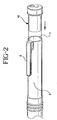
- FIG. 2 is an exploded perspective view of a cap 3 on a medication delivery pen 1 and a pen needle magazine dispenser 10, according to the present invention.
- Cap 3 includes a clip 5 and an open end 7 dimensioned to receive pen needle magazine dispenser 10.
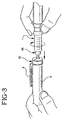
- Fig. 3 is a perspective view showing the operation of inserting an adaptor 50 on distal end 6 of medication delivery pen 1 into pen needle magazine dispenser 10 and the rotational motion used to attach a pen needle assembly 100 to adaptor 50.
- pen needle magazine dispenser 10 includes a cover 20 and a container 30.
- Container 30 includes a plurality of cavities 31 about the circumference of container 30, with each cavity 31 dimensioned to receive a pen needle assembly 100, described further below.
- Each pen needle assembly 100 is originally sealed in its respective cavity 31 by a disc shaped label or sterility barrier 150 that is attached to an upper surface 32 of container 30.
- Label 150 provides sterility for unused pen needle assemblies 100 contained in each cavity 31 and a simple means for the user to identify whether the pen needle assembly in a particular cavity has been used.
- Pen needle magazine dispenser 10 is initially loaded with a predetermined number of pen needle assemblies 100 in the plurality of cavities 31, with all of the cavities 31 being sealed by sterility barrier 150 and having a number 151 thereon corresponding to each cavity 31.
- Each number 151 or other indicia on label 150 indicates to the user how many unused pen needle assemblies 100 remain in pen needle magazine dispenser 10.
- Label 150 includes a central opening 152 through which cover 20 is mounted on container 30 and is scored at the location of each cavity 31 without, of course, affecting the integrity of the seal to allow for controlled breaking when adaptor 50 on medication delivery pen 1 is pressed through label 150 when loading pen needle assembly 100 on adaptor 50. The controlled breaking of the scored area allows adaptor 50 on medication delivery pen 1 to be inserted through label 150 to mate with pen needle assembly 100 within cavity 31.
- container 30 includes a central opening 37 and a plurality of ratchet teeth 33 selectively spaced around an outer wall 35 of container 30.
- Container 30 also includes a flange 34 that extends outwardly from outer wall 35 of container 30 below ratchet teeth 33 and an end of travel lock pin 36 that extends up from flange 34. End of travel lock pin 36 works with a similar end of travel lock key 26 located on the underside of cover 20 to stop rotation of cover 20 on container 30 when all cavities have passed under slot 21.
- Cover 20 includes a central post 22 having an enlarged head 23.
- cover 20 includes an outer lip 27 around its circumference that extends down and over container 30, when cover 20 is attached to container 30.
- Outer lip 27 includes a ratchet tooth 25 extending therefrom in the direction of container 30 that is dimensioned to work with the plurality of ratchet teeth 33 on container 30 to prevent cover 20 from rotating in a predetermined direction.
- Cover 20 is rotatably attached to container 30 after container 30 has been loaded with pen needle assemblies 100 and label 150 has been attached to upper surface 32 of container 30 by inserting central post 22 into central opening 37 in container 30 until enlarged head 23 snaps to central opening 37.
- cover 20 When enlarged head 23 snaps into central opening 37, cover 20 is attached to container 30 such that ratchet teeth 33 on container 30 engage with ratchet tooth 25 extending from cover 20 to only permit cover 20 to rotate in one direction, i.e., a clockwise direction. Therefore, cover 20 is not permitted to rotate in the counter-clockwise direction or to move slot 21 back over cavities 31 containing used pen needles 100.
- cover 20 when cover 20 is attached to container 30 it is important to locate end of travel lock key 26 on cover 20 adjacent to end of travel lock pin 36 on container 30, such that cover 20 can proceed with a full clockwise rotation on container 30. Therefore, when all cavities have been accessed using slot 21 on cover 20 and cover 20 has completed a complete clockwise rotation on container 30, end of travel lock key 26 on cover 20 will again be adjacent to end of travel lock pin 36 on container 30 but now will prevent further rotation in the clockwise direction. In the current embodiment, cover 20 can never be rotated in the counter-clockwise direction on container 30 because of the above-described interaction of ratchet teeth 25 and 33.
- container 30 includes a plurality of cavities 31 around its circumference that are dimensioned to receive pen needle assemblies 100, more clearly shown in Figs. 5 and 6 and further described below.
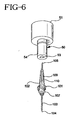
- Fig. 5 shows a cross-sectional view of one of said plurality of cavities 31 and Fig. 6 more clearly shows adaptor 50.
- each cavity 31 includes an open end 39 leading to an upper section 42 and a bottom section 41 leading to a closed end 44.
- Upper section 42 includes a retaining ring 46 that mates with a matching retaining ring 55 on adaptor 50, when adaptor 50 is inserted into cavity 31 to attach or detach pen needle assembly 100 to adaptor 50.
- Bottom section 41 has a smaller diameter than upper section 42 with a shelf 43 formed where sections 41 and 42 meet.
- a set of threads 45 are located in the bottom part of upper section 42 adjacent to shelf 43 and bottom section 41 is dimensioned to receive a distal point 104 on pen needle assembly 100.
- pen needle assembly 100 includes a hub 102 having a triangular shaped proximal end 109 and a distal end 107 having a set of threads 101 thereon dimensioned to mate with the set of threads 45 within cavities 31.
- a needle cannula 103 is mounted within hub 102 and includes a distal point 104 and a proximal point 105, wherein proximal point 105 extends from triangular shaped proximal end 109 and distal point 104 extends out of distal end 107 on hub 102.
- Proximal end 109 also includes one or more splines 110 to improve the rotational operation of hub 102 within cavity 31 and increase the force-fit between hub 102 and adaptor 50.
- each pen needle assembly 100 within cavity 31 can be removed and mounted on a medication delivery pen having an adaptor 50.
- adaptor 50 includes an open proximal end 51 having a set of threads 52 dimensioned to mate with threads 8 on distal end 6 of conventional medication delivery pen 1.
- Adaptor 50 also includes a unique triangular shaped opening 53 in its distal end 54. After adaptor 50 has been threaded onto distal end 6 of pen 1, distal end 54 of adaptor 50 is used to remove pen needle assembly 100 from cavity 31 by inserting triangular shaped proximal end 109 of needle assembly 100 into triangular shaped opening 53 in adaptor 50.
- proximal point 105 of pen needle assembly 100 pierces rubber septum 2 of the cartridge in pen 1 to place needle cannula 103 in communication with medication contained within the cartridge in pen 1.
- the forced fit also holds proximal point 105 within rubber septum 2 and needle assembly 100 within adaptor 50 during the injection of medication from the cartridge in pen 1.
- the used pen needle assembly 100 mounted on adaptor 50 on medication delivery pen 1 is reinserted into cavity 31 until retaining rings 46 and 55 mate and the set of threads 101 on pen needle assembly 100 come into contact with the set of threads 45 within cavity 31.
- Medication delivery pen 1 is then rotated in the opposite direction to thread pen needle assembly 100 back into cavity 31 and pen 1 is then pulled out of container 30 as pen needle assembly 100 is pulled out adaptor 50.
- cover 20 The user then rotates cover 20 until slot 21 is aligned with the next cavity 31 having an unused pen needle 100 that is still covered by label 150.
- cover 20 As cover 20 is rotated ratchet tooth 25 travels over one set of ratchet teeth 33 on container 30, which then prevents cover 20 from rotating in the opposite direction.
- ratchet tooth 25 travels over one set of ratchet teeth 33 on container 30, which then prevents cover 20 from rotating in the opposite direction.
- an alternative to the uni-directional cover shown in the drawings and described above would be a design that allows the user to rotate slot 21 back to previously used needles. In that case, no ratchet mechanism would be needed but the other features of the present invention could still be used in such a device.
- the current design allows the user to repeatedly rotate cover 20 to each cavity 31 until all of the pen needle assemblies 100 have been used and the last cavity 31 has been encountered by slot 21 on cover 20. That last cavity could be left empty so that the user will know that all pen needle assemblies 100 have been used and thereby indicate that pen needle magazine dispenser 10 should now be properly disposed of.
- cover 20 would no longer be able to rotate in either direction. As explained above, further rotation would be prevented by interaction between end of travel lock pin 36 on container 30 and end of travel lock key 26 on cover 20.
- the apparatus of the present invention can have a final rotational movement that is limted to a one-half (1/2) unit turn. In that case, slot 21 would be finally positioned between the first cavity and the last cavity with all pen needle assemblies 100 being covered and contained within container 30 and cover 20 being prevented from rotation in either direction.
- adaptor 50 can be integrally molded onto or permanently attached to distal end 6 of a medication delivery pen 1 rather than being a separate part.
Description
Claims (6)
- An apparatus (10) for storing and dispensing a plurality of needle assemblies for use on a medication delivery pen (1) having a removable cap (3), said apparatus comprising:a container (30) having an upper surface including a plurality of cavities (31) with each cavity (31) being dimensioned to receive a needle assembly (100);means (50) for attaching said container on a medication delivery pen (1); anda cover (20) rotatably mounted on said container (30), said cover (20) having a slot (21) that can be rotated into alignment with one of said plurality of cavities (31) in said container (30) to provide access through said cover (20) to a needle assembly (100) located in said one of said plurality of cavities (31), wherein the attaching means comprises means for mounting said container within an open end (7) of a removable cap (3) on the medication delivery pen.
- An apparatus according to Claim 1, further comprising a sterility barrier (15) over each of said plurality of cavities (31).
- An apparatus according to Claim 2, wherein each of said sterility barrier includes an indicia (151) that identifies the number of unused needle assemblies (100) remaining in the apparatus.
- An apparatus according to Claim 3, wherein said sterility barrier (150) includes scoring over each of said plurality of cavities (31) to permit said sterility barrier (150) to be pierced by the medication delivery pen (1) accessing said cavity (31) behind said scoring.
- An apparatus according to Claim 1, further comprising means (45, 101) for attaching one of said needle assemblies (100) onto the medication delivery pen (1).
- An apparatus according to Claim 1, wherein said attaching means includes an adaptor (50) having a set of threads (52) that mate with a set of threads (8) on a distal end (6) of the medication delivery pen (1) to attach said adaptor (50) to the medication delivery pen (1).
Applications Claiming Priority (3)
| Application Number | Priority Date | Filing Date | Title |
|---|---|---|---|
| US92819697A | 1997-09-12 | 1997-09-12 | |
| US928275 | 1997-09-12 | ||
| US08/928,275 US5829589A (en) | 1997-09-12 | 1997-09-12 | Pen needle magazine dispenser |
Publications (3)
| Publication Number | Publication Date |
|---|---|
| EP0903155A2 EP0903155A2 (en) | 1999-03-24 |
| EP0903155A3 EP0903155A3 (en) | 1999-07-07 |
| EP0903155B1 true EP0903155B1 (en) | 2002-06-05 |
Family
ID=27129957
Family Applications (2)
| Application Number | Title | Priority Date | Filing Date |
|---|---|---|---|
| EP98307082A Expired - Lifetime EP0903155B1 (en) | 1997-09-12 | 1998-09-03 | Dispensing magazine for pen needles |
| EP98307108A Expired - Lifetime EP0903158B1 (en) | 1997-09-12 | 1998-09-03 | Pen needle |
Family Applications After (1)
| Application Number | Title | Priority Date | Filing Date |
|---|---|---|---|
| EP98307108A Expired - Lifetime EP0903158B1 (en) | 1997-09-12 | 1998-09-03 | Pen needle |
Country Status (5)
| Country | Link |
|---|---|
| US (1) | US5829589A (en) |
| EP (2) | EP0903155B1 (en) |
| JP (3) | JP4339429B2 (en) |
| CA (2) | CA2244960A1 (en) |
| DE (2) | DE69805584T2 (en) |
Families Citing this family (165)
| Publication number | Priority date | Publication date | Assignee | Title |
|---|---|---|---|---|
| US6391005B1 (en) | 1998-03-30 | 2002-05-21 | Agilent Technologies, Inc. | Apparatus and method for penetration with shaft having a sensor for sensing penetration depth |
| DE19840856B4 (en) * | 1998-09-07 | 2008-04-10 | Roche Diagnostics Gmbh | System for obtaining a body fluid, lancet magazine, lancet, lancet set, lancing device and method for removing a lancet from a lancet magazine and use of the system |
| US7077828B2 (en) * | 1999-03-05 | 2006-07-18 | Roche Diagnostics Gmbh | Device for withdrawing blood for diagnostic applications |
| US6323501B1 (en) * | 1999-03-12 | 2001-11-27 | Theragenics Corporation | Container for storing and shipping radioactive materials |
| US6183150B1 (en) * | 2000-01-19 | 2001-02-06 | Peripheral Technology Inc. | Computer key |
| DE10010694A1 (en) | 2000-03-04 | 2001-09-06 | Roche Diagnostics Gmbh | Lancet including tipped needle with body surrounding tip |
| WO2001093927A1 (en) * | 2000-06-09 | 2001-12-13 | Novo Nordisk A/S | A needle magazine |
| US6666377B1 (en) * | 2000-07-18 | 2003-12-23 | Scott C. Harris | Bar code data entry device |
| US6986760B2 (en) | 2000-08-02 | 2006-01-17 | Becton, Dickinson And Company | Pen needle and safety shield system |
| JP5058425B2 (en) | 2000-08-02 | 2012-10-24 | ベクトン・ディキンソン・アンド・カンパニー | Pen needle and safety shield system |
| AU2001272374A1 (en) * | 2000-08-03 | 2002-02-18 | Novo-Nordisk A/S | A needle magazine |
| US8641644B2 (en) | 2000-11-21 | 2014-02-04 | Sanofi-Aventis Deutschland Gmbh | Blood testing apparatus having a rotatable cartridge with multiple lancing elements and testing means |
| US6472675B2 (en) | 2000-12-15 | 2002-10-29 | Theragenics Corporation | Container for storing and shipping needle cartridges |
| CA2435439A1 (en) * | 2001-01-22 | 2002-07-25 | F. Hoffmann-La Roche Ag | Lancet device having capillary action |
| US7749174B2 (en) | 2001-06-12 | 2010-07-06 | Pelikan Technologies, Inc. | Method and apparatus for lancet launching device intergrated onto a blood-sampling cartridge |
| US9226699B2 (en) | 2002-04-19 | 2016-01-05 | Sanofi-Aventis Deutschland Gmbh | Body fluid sampling module with a continuous compression tissue interface surface |
| US9427532B2 (en) | 2001-06-12 | 2016-08-30 | Sanofi-Aventis Deutschland Gmbh | Tissue penetration device |
| US8337419B2 (en) | 2002-04-19 | 2012-12-25 | Sanofi-Aventis Deutschland Gmbh | Tissue penetration device |
| US7041068B2 (en) | 2001-06-12 | 2006-05-09 | Pelikan Technologies, Inc. | Sampling module device and method |
| US7981056B2 (en) | 2002-04-19 | 2011-07-19 | Pelikan Technologies, Inc. | Methods and apparatus for lancet actuation |
| US7033371B2 (en) | 2001-06-12 | 2006-04-25 | Pelikan Technologies, Inc. | Electric lancet actuator |
| US7344507B2 (en) | 2002-04-19 | 2008-03-18 | Pelikan Technologies, Inc. | Method and apparatus for lancet actuation |
| CA2448902C (en) | 2001-06-12 | 2010-09-07 | Pelikan Technologies, Inc. | Self optimizing lancing device with adaptation means to temporal variations in cutaneous properties |
| US9795747B2 (en) | 2010-06-02 | 2017-10-24 | Sanofi-Aventis Deutschland Gmbh | Methods and apparatus for lancet actuation |
| DE10142232B4 (en) | 2001-08-29 | 2021-04-29 | Roche Diabetes Care Gmbh | Process for the production of an analytical aid with a lancet and test element |
| US6561363B1 (en) * | 2001-10-23 | 2003-05-13 | Mgw Group, Inc. | Display assembly for edible and non-edible objects |
| US9314194B2 (en) | 2002-04-19 | 2016-04-19 | Sanofi-Aventis Deutschland Gmbh | Tissue penetration device |
| US9248267B2 (en) | 2002-04-19 | 2016-02-02 | Sanofi-Aventis Deustchland Gmbh | Tissue penetration device |
| US7674232B2 (en) | 2002-04-19 | 2010-03-09 | Pelikan Technologies, Inc. | Method and apparatus for penetrating tissue |
| US8784335B2 (en) | 2002-04-19 | 2014-07-22 | Sanofi-Aventis Deutschland Gmbh | Body fluid sampling device with a capacitive sensor |
| US7229458B2 (en) | 2002-04-19 | 2007-06-12 | Pelikan Technologies, Inc. | Method and apparatus for penetrating tissue |
| US7331931B2 (en) | 2002-04-19 | 2008-02-19 | Pelikan Technologies, Inc. | Method and apparatus for penetrating tissue |
| US7232451B2 (en) | 2002-04-19 | 2007-06-19 | Pelikan Technologies, Inc. | Method and apparatus for penetrating tissue |
| US7547287B2 (en) | 2002-04-19 | 2009-06-16 | Pelikan Technologies, Inc. | Method and apparatus for penetrating tissue |
| US9795334B2 (en) | 2002-04-19 | 2017-10-24 | Sanofi-Aventis Deutschland Gmbh | Method and apparatus for penetrating tissue |
| US8579831B2 (en) | 2002-04-19 | 2013-11-12 | Sanofi-Aventis Deutschland Gmbh | Method and apparatus for penetrating tissue |
| US7892183B2 (en) | 2002-04-19 | 2011-02-22 | Pelikan Technologies, Inc. | Method and apparatus for body fluid sampling and analyte sensing |
| US7976476B2 (en) | 2002-04-19 | 2011-07-12 | Pelikan Technologies, Inc. | Device and method for variable speed lancet |
| US7909778B2 (en) | 2002-04-19 | 2011-03-22 | Pelikan Technologies, Inc. | Method and apparatus for penetrating tissue |
| US8221334B2 (en) | 2002-04-19 | 2012-07-17 | Sanofi-Aventis Deutschland Gmbh | Method and apparatus for penetrating tissue |
| US8372016B2 (en) | 2002-04-19 | 2013-02-12 | Sanofi-Aventis Deutschland Gmbh | Method and apparatus for body fluid sampling and analyte sensing |
| US20120238907A1 (en) * | 2002-04-19 | 2012-09-20 | Dirk Boecker | Method and apparatus for body fluid sampling with hybrid actuation |
| US8267870B2 (en) * | 2002-04-19 | 2012-09-18 | Sanofi-Aventis Deutschland Gmbh | Method and apparatus for body fluid sampling with hybrid actuation |
| US7297122B2 (en) | 2002-04-19 | 2007-11-20 | Pelikan Technologies, Inc. | Method and apparatus for penetrating tissue |
| US7491178B2 (en) | 2002-04-19 | 2009-02-17 | Pelikan Technologies, Inc. | Method and apparatus for penetrating tissue |
| US8360992B2 (en) | 2002-04-19 | 2013-01-29 | Sanofi-Aventis Deutschland Gmbh | Method and apparatus for penetrating tissue |
| US7226461B2 (en) | 2002-04-19 | 2007-06-05 | Pelikan Technologies, Inc. | Method and apparatus for a multi-use body fluid sampling device with sterility barrier release |
| US8702624B2 (en) | 2006-09-29 | 2014-04-22 | Sanofi-Aventis Deutschland Gmbh | Analyte measurement device with a single shot actuator |
| US7901362B2 (en) | 2002-04-19 | 2011-03-08 | Pelikan Technologies, Inc. | Method and apparatus for penetrating tissue |
| DE10222235A1 (en) * | 2002-05-16 | 2003-11-27 | Roche Diagnostics Gmbh | Blood Collection system |
| DE10223558A1 (en) * | 2002-05-28 | 2003-12-11 | Roche Diagnostics Gmbh | System useful in withdrawing blood for diagnostic purposes, has housing, lancet guide and lancet drive provided with drive spring, cocking device, drive rotor and outputs side coupling mechanism |
| DE10231564B3 (en) * | 2002-07-11 | 2004-02-26 | Rigling, Heinz | Collection and disposal containers, in particular for cannulas |
| DE10255134A1 (en) * | 2002-11-26 | 2004-06-09 | Tecpharma Licensing Ag | Puller for injection needles |
| US8574895B2 (en) | 2002-12-30 | 2013-11-05 | Sanofi-Aventis Deutschland Gmbh | Method and apparatus using optical techniques to measure analyte levels |
| DE10302501A1 (en) * | 2003-01-23 | 2004-08-05 | Roche Diagnostics Gmbh | Device and method for absorbing a body fluid for analysis purposes |
| ES2347248T3 (en) | 2003-05-30 | 2010-10-27 | Pelikan Technologies Inc. | PROCEDURE AND APPLIANCE FOR FLUID INJECTION. |
| US6883268B2 (en) * | 2003-05-31 | 2005-04-26 | Richard T. Fraser | Bucket tackle system |
| WO2004107964A2 (en) | 2003-06-06 | 2004-12-16 | Pelikan Technologies, Inc. | Blood harvesting device with electronic control |
| WO2006001797A1 (en) | 2004-06-14 | 2006-01-05 | Pelikan Technologies, Inc. | Low pain penetrating |
| MXPA05013744A (en) * | 2003-06-17 | 2006-06-27 | Adst Technologies Ltd | Fluid transfer device having removable needle cartridge. |
| US8932264B2 (en) | 2003-08-11 | 2015-01-13 | Becton, Dickinson And Company | Medication delivery pen assembly with needle locking safety shield |
| WO2005033659A2 (en) | 2003-09-29 | 2005-04-14 | Pelikan Technologies, Inc. | Method and apparatus for an improved sample capture device |
| US9351680B2 (en) | 2003-10-14 | 2016-05-31 | Sanofi-Aventis Deutschland Gmbh | Method and apparatus for a variable user interface |
| GB2408255A (en) * | 2003-11-18 | 2005-05-25 | Stephen Frederick Marston | Container system for hypodermic needle packs for insulin injection |
| EP1706026B1 (en) | 2003-12-31 | 2017-03-01 | Sanofi-Aventis Deutschland GmbH | Method and apparatus for improving fluidic flow and sample capture |
| US7822454B1 (en) | 2005-01-03 | 2010-10-26 | Pelikan Technologies, Inc. | Fluid sampling device with improved analyte detecting member configuration |
| CA2559750C (en) | 2004-03-31 | 2014-01-07 | Eli Lilly And Company | Injection apparatus having a needle cassette for delivering a pharmaceutical liquid |
| US8828203B2 (en) | 2004-05-20 | 2014-09-09 | Sanofi-Aventis Deutschland Gmbh | Printable hydrogels for biosensors |
| GB2414734B (en) * | 2004-06-01 | 2010-09-08 | Rosti As | Devices for retaining and presenting for use a plurality of components |
| US9820684B2 (en) | 2004-06-03 | 2017-11-21 | Sanofi-Aventis Deutschland Gmbh | Method and apparatus for a fluid sampling device |
| US9775553B2 (en) | 2004-06-03 | 2017-10-03 | Sanofi-Aventis Deutschland Gmbh | Method and apparatus for a fluid sampling device |
| US7604604B2 (en) * | 2004-09-09 | 2009-10-20 | Roche Diagnostics Operations, Inc. | Device for sampling bodily fluids |
| US7645241B2 (en) | 2004-09-09 | 2010-01-12 | Roche Diagnostics Operations, Inc. | Device for sampling bodily fluids |
| US8652831B2 (en) | 2004-12-30 | 2014-02-18 | Sanofi-Aventis Deutschland Gmbh | Method and apparatus for analyte measurement test time |
| US7618396B2 (en) * | 2006-08-09 | 2009-11-17 | Avant Medical Corp. | Injection system with hidden needles |
| WO2008150715A1 (en) * | 2007-05-30 | 2008-12-11 | Eli Lilly And Company | Cartridge with multiple injection needles for a medication injection device |
| EP2185225A1 (en) * | 2007-07-28 | 2010-05-19 | Novo Nordisk A/S | A needle magazine |
| US8961431B2 (en) * | 2009-09-28 | 2015-02-24 | Roche Diagnostics Operations, Inc. | Body fluid lancing, acquiring, and testing cartridge design |
| US9186097B2 (en) * | 2007-09-17 | 2015-11-17 | Roche Diabetes Care, Inc. | Body fluid lancing, acquiring, and testing cartridge design |
| EP2050392B1 (en) * | 2007-10-15 | 2012-09-05 | Roche Diagnostics GmbH | Lancet wheel |
| EP3153198A1 (en) * | 2008-01-15 | 2017-04-12 | Becton, Dickinson and Company | Medical injector with pen needle assembly |
| WO2009126900A1 (en) | 2008-04-11 | 2009-10-15 | Pelikan Technologies, Inc. | Method and apparatus for analyte detecting device |
| EP2113197A1 (en) * | 2008-05-03 | 2009-11-04 | Roche Diagnostics GmbH | Lancet wheel and method for manufacturing a lancet wheel |
| WO2010048752A1 (en) * | 2008-10-29 | 2010-05-06 | Pan Qiubao | Needle-replacing apparatus mating with split-type continuous injector |
| US20100106137A1 (en) * | 2008-10-29 | 2010-04-29 | Warsaw Orthopedic, Inc. | Drug Delivery System |
| WO2010084113A1 (en) | 2009-01-20 | 2010-07-29 | Novo Nordisk A/S | Drug delivery device with reservoir comprising window coverable by needle magazine |
| US9375169B2 (en) | 2009-01-30 | 2016-06-28 | Sanofi-Aventis Deutschland Gmbh | Cam drive for managing disposable penetrating member actions with a single motor and motor and control system |
| CA2770558A1 (en) * | 2009-08-12 | 2011-02-17 | Sanofi-Aventis Deutschland Gmbh | Cap for a portable medical delivery device and such a medical delivery device |
| CA3016519C (en) * | 2009-09-18 | 2020-05-26 | Becton, Dickinson And Company | Separable hub post of pen needle |
| GB0916909D0 (en) * | 2009-09-25 | 2009-11-11 | Exchange Supplies Ltd | Container for disposal of syringe needles |
| US8882706B2 (en) | 2009-12-04 | 2014-11-11 | Becton, Dickinson And Company | Pen needle removal device for a drug delivery device |
| WO2011083055A1 (en) | 2010-01-05 | 2011-07-14 | Novo Nordisk A/S | Method for forming collapsible reservoir |
| US9849247B2 (en) | 2010-02-01 | 2017-12-26 | Becton, Dickinson And Company | Low dose prefilled drug delivery device and method |
| JP5771225B2 (en) | 2010-03-05 | 2015-08-26 | ノボ・ノルデイスク・エー/エス | Needle magazine |
| JP5828886B2 (en) * | 2010-04-09 | 2015-12-09 | サノフィ−アベンティス・ドイチュラント・ゲゼルシャフト・ミット・ベシュレンクテル・ハフツング | Coded cap for use with drug delivery devices |
| US8965476B2 (en) | 2010-04-16 | 2015-02-24 | Sanofi-Aventis Deutschland Gmbh | Tissue penetration device |
| US9216253B2 (en) | 2010-08-16 | 2015-12-22 | Becton, Dickinson And Company | Needle dispensing and storing apparatus for medicament delivery device |
| US8876780B2 (en) | 2010-08-16 | 2014-11-04 | Becton, Dickinson And Company | Attachable needle changing device for medicament delivery device |
| US9101724B2 (en) | 2010-08-16 | 2015-08-11 | Becton, Dickinson And Company | Pen injection device needle dispensing and storing apparatus |
| US8887912B2 (en) * | 2010-08-16 | 2014-11-18 | Becton, Dickinson And Company | Living hinge needle assembly for medicament delivery device |
| US9107988B2 (en) * | 2010-08-16 | 2015-08-18 | Becton, Dickinson And Company | Circuitous band needle changing apparatus |
| US9125975B2 (en) | 2010-08-16 | 2015-09-08 | Becton, Dickinson And Company | User-actuated storage assembly for injection device |
| EP2640444B1 (en) * | 2010-11-19 | 2017-05-10 | Eli Lilly and Company | Needle magazine for medication injection device |
| US8158428B1 (en) | 2010-12-30 | 2012-04-17 | General Electric Company | Methods, systems and apparatus for detecting material defects in combustors of combustion turbine engines |
| US9717452B2 (en) | 2010-12-30 | 2017-08-01 | Roche Diabetes Care, Inc. | Handheld medical diagnostic devices with lancing speed control |
| US8852123B2 (en) | 2010-12-30 | 2014-10-07 | Roche Diagnostics Operations, Inc. | Handheld medical diagnostic devices housing with sample transfer |
| WO2012089821A1 (en) | 2010-12-31 | 2012-07-05 | Novo Nordisk A/S | Medical injection device |
| EP2491971A1 (en) * | 2011-02-23 | 2012-08-29 | Sanofi-Aventis Deutschland GmbH | Needle adapter |
| EP2522378A1 (en) * | 2011-05-11 | 2012-11-14 | Sanofi-Aventis Deutschland GmbH | Needle assembly storage device |
| WO2012164097A1 (en) | 2011-06-01 | 2012-12-06 | Novo Nordisk A/S | Medical device having user friendly control input |
| EP2540329A1 (en) | 2011-06-28 | 2013-01-02 | Sanofi-Aventis Deutschland GmbH | Needle assembly attachment and removal device |
| US8556183B2 (en) * | 2011-07-08 | 2013-10-15 | Gregory D. Bray | Systems and methods involving transferable identification tags |
| SG192312A1 (en) | 2012-02-02 | 2013-08-30 | Becton Dickinson Holdings Pte Ltd | Adaptor for coupling to a medical container |
| IN2014DN06930A (en) | 2012-02-02 | 2015-04-10 | Becton Dickinson Holdings Pte Ltd | |
| SG192310A1 (en) | 2012-02-02 | 2013-08-30 | Becton Dickinson Holdings Pte Ltd | Adaptor for coupling to a medical container |
| GB201208024D0 (en) * | 2012-05-08 | 2012-06-20 | Berry Alexander C | Suturing device |
| EP2732835A1 (en) * | 2012-11-14 | 2014-05-21 | Sanofi-Aventis Deutschland GmbH | Needle assembly magazine |
| EP2735300A1 (en) * | 2012-11-26 | 2014-05-28 | Becton Dickinson France | Adaptor for multidose medical container |
| US10350371B2 (en) | 2012-12-26 | 2019-07-16 | Becton, Dickinson And Company | Pen needle assembly |
| JP1526207S (en) | 2013-08-05 | 2015-06-15 | ||
| GB201315030D0 (en) | 2013-08-22 | 2013-10-02 | Knight Martin | Magazine |
| US10912898B1 (en) | 2014-02-03 | 2021-02-09 | Medical Device Engineering Llc | Tamper evident cap for medical fitting |
| KR101579073B1 (en) * | 2014-07-21 | 2015-12-22 | 주식회사 종근당 | ointment dispenser which the applicator in each |
| US9775978B2 (en) | 2014-07-25 | 2017-10-03 | Warsaw Orthopedic, Inc. | Drug delivery device and methods having a retaining member |
| US10080877B2 (en) | 2014-07-25 | 2018-09-25 | Warsaw Orthopedic, Inc. | Drug delivery device and methods having a drug cartridge |
| GB201413933D0 (en) * | 2014-08-06 | 2014-09-17 | Owen Mumford Ltd | Needle tip arrangements |
| DE202014103829U1 (en) | 2014-08-19 | 2014-09-10 | IME-DC GmbH International Medical Equipment - Diabetes Care | Magazine for at least one hypodermic injection needle |
| DE102014111789A1 (en) | 2014-08-19 | 2016-02-25 | IME-DC GmbH International Medical Equipment - Diabetes Care | Magazine for at least one hypodermic injection needle |
| EP2987516B1 (en) | 2014-08-19 | 2018-01-10 | IME-DC GmbH International Medical Equipment - Diabetes Care | Cartridge for at least one subcutaneous injection needle |
| US10704944B2 (en) | 2014-09-14 | 2020-07-07 | Becton, Dickinson And Company | System and method for capturing dose information |
| US10971260B2 (en) | 2014-09-14 | 2021-04-06 | Becton, Dickinson And Company | System and method for capturing dose information |
| ITUB20152531A1 (en) * | 2015-07-28 | 2017-01-28 | Health Robotics Srl | CONTAINER FOR CLOSING CAPS OF SYRINGES |
| US10076650B2 (en) | 2015-11-23 | 2018-09-18 | Warsaw Orthopedic, Inc. | Enhanced stylet for drug depot injector |
| TW201729859A (en) | 2015-11-27 | 2017-09-01 | 賽諾菲阿凡提斯德意志有限公司 | A cap for an injection device |
| EP3448477A4 (en) | 2016-04-28 | 2019-10-02 | Becton, Dickinson and Company | Pen needle magazine |
| JP6952714B2 (en) | 2016-04-28 | 2021-10-20 | ベクトン・ディキンソン・アンド・カンパニーBecton, Dickinson And Company | Pen needle magazine |
| WO2017189168A1 (en) | 2016-04-28 | 2017-11-02 | Becton, Dickinson And Company | Pen needle exchange system |
| WO2017189165A1 (en) | 2016-04-28 | 2017-11-02 | Becton, Dickinson And Company | Pen needle magazine |
| CN109069728B (en) | 2016-04-28 | 2021-08-13 | 贝克顿·迪金森公司 | Needle storage cartridge with status indicator |
| WO2017189164A1 (en) | 2016-04-28 | 2017-11-02 | Becton, Dickinson And Company | Pen needle magazine |
| CN109069344B (en) | 2016-04-28 | 2021-06-11 | 贝克顿·迪金森公司 | Pen needle exchange system |
| CA3018771A1 (en) | 2016-04-28 | 2017-11-02 | Becton, Dickinson And Company | Pen needle magazine |
| WO2017189909A1 (en) * | 2016-04-28 | 2017-11-02 | Becton, Dickinson And Company | Needle storage magazine assembly |
| WO2017189172A1 (en) | 2016-04-28 | 2017-11-02 | Becton, Dickinson And Company | Needle storage magazine assembly |
| EP3448473B1 (en) | 2016-04-28 | 2021-10-27 | Becton, Dickinson and Company | Pen needle magazine |
| CA3019827A1 (en) * | 2016-04-28 | 2017-11-02 | Becton, Dickinson And Company | Radial needle storage magazine |
| EP3448474A4 (en) | 2016-04-28 | 2019-10-23 | Becton, Dickinson and Company | Pen needle magazine |
| US10549081B2 (en) | 2016-06-23 | 2020-02-04 | Warsaw Orthopedic, Inc. | Drug delivery device and methods having a retaining member |
| US10434261B2 (en) | 2016-11-08 | 2019-10-08 | Warsaw Orthopedic, Inc. | Drug pellet delivery system and method |
| US10758684B1 (en) | 2017-03-03 | 2020-09-01 | Jonathan J. Vitello | Tamper evident assembly |
| US10888672B1 (en) | 2017-04-06 | 2021-01-12 | International Medical Industries, Inc. | Tamper evident closure assembly for a medical device |
| US10898659B1 (en) * | 2017-05-19 | 2021-01-26 | International Medical Industries Inc. | System for handling and dispensing a plurality of products |
| WO2019005495A1 (en) * | 2017-06-27 | 2019-01-03 | Becton, Dickinson And Company | Pen needle multiple carrier injection system |
| CA3085349A1 (en) * | 2017-12-28 | 2019-07-04 | Becton, Dickinson And Company | Pen needle assembly apparatus |
| US11446212B2 (en) | 2018-02-01 | 2022-09-20 | Embecta Corp. | Multiple cavity carrier apparatuses for detecting removal of items from cavities and their replacement |
| JP7234368B2 (en) * | 2018-11-29 | 2023-03-07 | エンベクタ コーポレイション | Injection pens and adapters for injection pens |
| CA3134314A1 (en) * | 2019-04-26 | 2020-10-29 | Becton, Dickinson And Company | Pen assembly |
| US11911339B1 (en) | 2019-08-15 | 2024-02-27 | Peter Lehel | Universal additive port cap |
| US11697527B1 (en) | 2019-09-11 | 2023-07-11 | Logan Hendren | Tamper evident closure assembly |
| US11357588B1 (en) | 2019-11-25 | 2022-06-14 | Patrick Vitello | Needle packaging and disposal assembly |
| US11904149B1 (en) | 2020-02-18 | 2024-02-20 | Jonathan Vitello | Oral tamper evident closure with retained indicator |
| EP4135646A1 (en) * | 2020-04-16 | 2023-02-22 | Takeda Pharmaceutical Company Limited | Needle connectors and modular needle connectors for multi-dose drug delivery devices and methods thereof |
| US11938309B2 (en) | 2020-07-28 | 2024-03-26 | Neogen Corporation | Hypodermic interface assembly |
| US11523970B1 (en) | 2020-08-28 | 2022-12-13 | Jonathan Vitello | Tamper evident shield |
| US11872187B1 (en) | 2020-12-28 | 2024-01-16 | Jonathan Vitello | Tamper evident seal for a vial cover |
Family Cites Families (13)
| Publication number | Priority date | Publication date | Assignee | Title |
|---|---|---|---|---|
| US2168686A (en) * | 1934-11-20 | 1939-08-08 | Multiple Corp | Hypodermic syringe and cartridge |
| DK108590C (en) * | 1964-05-28 | 1968-01-08 | Novo Terapeutisk Labor As | Spray ampoule. |
| US3491757A (en) * | 1966-12-30 | 1970-01-27 | Raul Olvera Arce | Hypodermic syringe with non-turning tip connector |
| US3884229A (en) * | 1973-11-29 | 1975-05-20 | Burron Medical Prod Inc | Hypodermic syringe and needle assembly |
| GB1583157A (en) * | 1976-05-07 | 1981-01-21 | Kenova Ab | Syringes |
| DE3270634D1 (en) * | 1981-11-12 | 1986-05-22 | John Joseph Jacklich | A dental syringe |
| FR2623403B1 (en) * | 1987-11-20 | 1990-03-30 | Bacci Louis | PROCESS AND DEVICE FOR PLACING AND DEPOSITING SYRINGE NEEDLES, WITHOUT MANUAL CONTACT |
| NL8900208A (en) * | 1989-01-27 | 1990-08-16 | Hendrikus Gerrit Van Den Brink | Virus-contamination preventing syringe - has needle placed in clamped closed container attached to cylindrical part of syringe after use to prevent re-use |
| DE69121119T2 (en) * | 1990-02-09 | 1997-03-06 | Damal Ltd | Hypodermic needle / syringe connection and device for removing the needles therefrom |
| US5224596A (en) * | 1991-02-06 | 1993-07-06 | Kerry Kruger | Syringe carrier and recapping system |
| US5285896A (en) * | 1992-03-25 | 1994-02-15 | Timely Medical Innovations, Ltd. | Apparatus for receiving and capturing a hypodermic needle hub and cannula |
| US5354284A (en) * | 1992-06-09 | 1994-10-11 | Habley Medical Technology Corporation | Multiple injection syringe system |
| JPH09149781A (en) * | 1995-11-28 | 1997-06-10 | Kiotome Yamamoto | Cigarette case |
-
1997
- 1997-09-12 US US08/928,275 patent/US5829589A/en not_active Expired - Lifetime
-
1998
- 1998-08-12 CA CA002244960A patent/CA2244960A1/en not_active Abandoned
- 1998-08-12 CA CA002244759A patent/CA2244759C/en not_active Expired - Lifetime
- 1998-09-03 EP EP98307082A patent/EP0903155B1/en not_active Expired - Lifetime
- 1998-09-03 EP EP98307108A patent/EP0903158B1/en not_active Expired - Lifetime
- 1998-09-03 DE DE69805584T patent/DE69805584T2/en not_active Expired - Lifetime
- 1998-09-03 DE DE69805720T patent/DE69805720T2/en not_active Expired - Lifetime
- 1998-09-14 JP JP26071298A patent/JP4339429B2/en not_active Expired - Lifetime
- 1998-09-14 JP JP26071198A patent/JP4331287B2/en not_active Expired - Lifetime
-
2009
- 2009-03-18 JP JP2009066778A patent/JP4890579B2/en not_active Expired - Lifetime
Also Published As
| Publication number | Publication date |
|---|---|
| CA2244759C (en) | 2001-12-25 |
| EP0903158A3 (en) | 1999-07-07 |
| EP0903158B1 (en) | 2002-05-29 |
| EP0903155A2 (en) | 1999-03-24 |
| EP0903158A2 (en) | 1999-03-24 |
| JP4339429B2 (en) | 2009-10-07 |
| EP0903155A3 (en) | 1999-07-07 |
| JPH11146914A (en) | 1999-06-02 |
| US5829589A (en) | 1998-11-03 |
| JP4890579B2 (en) | 2012-03-07 |
| JP2009131685A (en) | 2009-06-18 |
| JPH11164889A (en) | 1999-06-22 |
| DE69805584T2 (en) | 2003-01-09 |
| DE69805584D1 (en) | 2002-07-04 |
| CA2244759A1 (en) | 1999-03-12 |
| DE69805720D1 (en) | 2002-07-11 |
| DE69805720T2 (en) | 2003-01-30 |
| JP4331287B2 (en) | 2009-09-16 |
| CA2244960A1 (en) | 1999-03-12 |
Similar Documents
| Publication | Publication Date | Title |
|---|---|---|
| EP0903155B1 (en) | Dispensing magazine for pen needles | |
| US5873462A (en) | Pen needle dispenser | |
| US6346094B2 (en) | Pen needle magazine | |
| US5931817A (en) | Pen needle assembly | |
| EP0688572B1 (en) | Time of last injection indicator for medication delivery pen | |
| US5941857A (en) | Disposable pen needle | |
| CA2155284C (en) | Pen needle dispenser | |
| JP2689372B2 (en) | Chemical supply pen | |
| EP2221078B1 (en) | Pen needle assembly for preventing under-torquing and over-torquing of pen needle | |
| JP3824649B2 (en) | Pen syringe with cartridge loading mechanism | |
| US20150034516A1 (en) | Living Hinge Needle Assembly For Medicament Delivery Device | |
| WO1993002921A1 (en) | Metered syringe filling device for pharmaceutical containers | |
| EP0702971B1 (en) | Dose setting knob adapter for medication delivery pen |
Legal Events
| Date | Code | Title | Description |
|---|---|---|---|
| PUAI | Public reference made under article 153(3) epc to a published international application that has entered the european phase |
Free format text: ORIGINAL CODE: 0009012 |
|
| AK | Designated contracting states |
Kind code of ref document: A2 Designated state(s): DE FR GB IT |
|
| AX | Request for extension of the european patent |
Free format text: AL;LT;LV;MK;RO;SI |
|
| PUAL | Search report despatched |
Free format text: ORIGINAL CODE: 0009013 |
|
| AK | Designated contracting states |
Kind code of ref document: A3 Designated state(s): AT BE CH CY DE DK ES FI FR GB GR IE IT LI LU MC NL PT SE |
|
| AX | Request for extension of the european patent |
Free format text: AL;LT;LV;MK;RO;SI |
|
| 17P | Request for examination filed |
Effective date: 20000106 |
|
| AKX | Designation fees paid |
Free format text: AT BE CH CY LI |
|
| RBV | Designated contracting states (corrected) |
Designated state(s): DE ES FR IT |
|
| REG | Reference to a national code |
Ref country code: DE Ref legal event code: 8566 |
|
| RBV | Designated contracting states (corrected) |
Designated state(s): DE FR GB IT |
|
| 17Q | First examination report despatched |
Effective date: 20010305 |
|
| RTI1 | Title (correction) |
Free format text: DISPENSING MAGAZINE FOR PEN NEEDLES |
|
| GRAG | Despatch of communication of intention to grant |
Free format text: ORIGINAL CODE: EPIDOS AGRA |
|
| RTI1 | Title (correction) |
Free format text: DISPENSING MAGAZINE FOR PEN NEEDLES |
|
| GRAG | Despatch of communication of intention to grant |
Free format text: ORIGINAL CODE: EPIDOS AGRA |
|
| GRAH | Despatch of communication of intention to grant a patent |
Free format text: ORIGINAL CODE: EPIDOS IGRA |
|
| RTI1 | Title (correction) |
Free format text: DISPENSING MAGAZINE FOR PEN NEEDLES |
|
| RTI1 | Title (correction) |
Free format text: DISPENSING MAGAZINE FOR PEN NEEDLES |
|
| GRAH | Despatch of communication of intention to grant a patent |
Free format text: ORIGINAL CODE: EPIDOS IGRA |
|
| GRAA | (expected) grant |
Free format text: ORIGINAL CODE: 0009210 |
|
| RIN1 | Information on inventor provided before grant (corrected) |
Inventor name: STEIN, JEFFREY A Inventor name: ALLEN, WILLIAM J Inventor name: REED, SCOTT Inventor name: MURRAY, MATTHEW Inventor name: WEST, ROBERT E Inventor name: DIBIASI, MICHAEL A Inventor name: NGUYEN, TUAN V. |
|
| AK | Designated contracting states |
Kind code of ref document: B1 Designated state(s): DE FR GB IT |
|
| REG | Reference to a national code |
Ref country code: GB Ref legal event code: FG4D |
|
| REF | Corresponds to: |
Ref document number: 69805720 Country of ref document: DE Date of ref document: 20020711 |
|
| ET | Fr: translation filed | ||
| PLBE | No opposition filed within time limit |
Free format text: ORIGINAL CODE: 0009261 |
|
| STAA | Information on the status of an ep patent application or granted ep patent |
Free format text: STATUS: NO OPPOSITION FILED WITHIN TIME LIMIT |
|
| 26N | No opposition filed |
Effective date: 20030306 |
|
| REG | Reference to a national code |
Ref country code: FR Ref legal event code: PLFP Year of fee payment: 19 |
|
| REG | Reference to a national code |
Ref country code: FR Ref legal event code: PLFP Year of fee payment: 20 |
|
| PGFP | Annual fee paid to national office [announced via postgrant information from national office to epo] |
Ref country code: IT Payment date: 20170828 Year of fee payment: 20 Ref country code: FR Payment date: 20170822 Year of fee payment: 20 Ref country code: GB Payment date: 20170821 Year of fee payment: 20 Ref country code: DE Payment date: 20170821 Year of fee payment: 20 |
|
| REG | Reference to a national code |
Ref country code: DE Ref legal event code: R071 Ref document number: 69805720 Country of ref document: DE |
|
| REG | Reference to a national code |
Ref country code: GB Ref legal event code: PE20 Expiry date: 20180902 |
|
| PG25 | Lapsed in a contracting state [announced via postgrant information from national office to epo] |
Ref country code: GB Free format text: LAPSE BECAUSE OF EXPIRATION OF PROTECTION Effective date: 20180902 |