EP0903654A2 - Control system, in particular for a palletisation unit with a robot - Google Patents
Control system, in particular for a palletisation unit with a robot Download PDFInfo
- Publication number
- EP0903654A2 EP0903654A2 EP98116930A EP98116930A EP0903654A2 EP 0903654 A2 EP0903654 A2 EP 0903654A2 EP 98116930 A EP98116930 A EP 98116930A EP 98116930 A EP98116930 A EP 98116930A EP 0903654 A2 EP0903654 A2 EP 0903654A2
- Authority
- EP
- European Patent Office
- Prior art keywords
- control
- robot
- control component
- module
- palletizing
- Prior art date
- Legal status (The legal status is an assumption and is not a legal conclusion. Google has not performed a legal analysis and makes no representation as to the accuracy of the status listed.)
- Granted
Links
Images


Classifications
-
- G—PHYSICS
- G05—CONTROLLING; REGULATING
- G05B—CONTROL OR REGULATING SYSTEMS IN GENERAL; FUNCTIONAL ELEMENTS OF SUCH SYSTEMS; MONITORING OR TESTING ARRANGEMENTS FOR SUCH SYSTEMS OR ELEMENTS
- G05B19/00—Programme-control systems
- G05B19/02—Programme-control systems electric
- G05B19/418—Total factory control, i.e. centrally controlling a plurality of machines, e.g. direct or distributed numerical control [DNC], flexible manufacturing systems [FMS], integrated manufacturing systems [IMS], computer integrated manufacturing [CIM]
-
- B—PERFORMING OPERATIONS; TRANSPORTING
- B65—CONVEYING; PACKING; STORING; HANDLING THIN OR FILAMENTARY MATERIAL
- B65G—TRANSPORT OR STORAGE DEVICES, e.g. CONVEYORS FOR LOADING OR TIPPING, SHOP CONVEYOR SYSTEMS OR PNEUMATIC TUBE CONVEYORS
- B65G57/00—Stacking of articles
- B65G57/02—Stacking of articles by adding to the top of the stack
- B65G57/03—Stacking of articles by adding to the top of the stack from above
-
- B—PERFORMING OPERATIONS; TRANSPORTING
- B25—HAND TOOLS; PORTABLE POWER-DRIVEN TOOLS; MANIPULATORS
- B25J—MANIPULATORS; CHAMBERS PROVIDED WITH MANIPULATION DEVICES
- B25J13/00—Controls for manipulators
- B25J13/06—Control stands, e.g. consoles, switchboards
-
- G—PHYSICS
- G05—CONTROLLING; REGULATING
- G05B—CONTROL OR REGULATING SYSTEMS IN GENERAL; FUNCTIONAL ELEMENTS OF SUCH SYSTEMS; MONITORING OR TESTING ARRANGEMENTS FOR SUCH SYSTEMS OR ELEMENTS
- G05B19/00—Programme-control systems
- G05B19/02—Programme-control systems electric
- G05B19/18—Numerical control [NC], i.e. automatically operating machines, in particular machine tools, e.g. in a manufacturing environment, so as to execute positioning, movement or co-ordinated operations by means of programme data in numerical form
- G05B19/414—Structure of the control system, e.g. common controller or multiprocessor systems, interface to servo, programmable interface controller
-
- Y—GENERAL TAGGING OF NEW TECHNOLOGICAL DEVELOPMENTS; GENERAL TAGGING OF CROSS-SECTIONAL TECHNOLOGIES SPANNING OVER SEVERAL SECTIONS OF THE IPC; TECHNICAL SUBJECTS COVERED BY FORMER USPC CROSS-REFERENCE ART COLLECTIONS [XRACs] AND DIGESTS
- Y02—TECHNOLOGIES OR APPLICATIONS FOR MITIGATION OR ADAPTATION AGAINST CLIMATE CHANGE
- Y02P—CLIMATE CHANGE MITIGATION TECHNOLOGIES IN THE PRODUCTION OR PROCESSING OF GOODS
- Y02P90/00—Enabling technologies with a potential contribution to greenhouse gas [GHG] emissions mitigation
- Y02P90/02—Total factory control, e.g. smart factories, flexible manufacturing systems [FMS] or integrated manufacturing systems [IMS]
Definitions
- the invention relates to a control system for robots, in particular for palletizing systems with robots, one robot and palletizing system components via a data transmission device are connected to a control device.
- Control systems for in particular palletizing systems with robots are well known.
- the control device consists of three different ones Assemblies, namely a robot sequence control system, one PLC unit and an external control panel.
- the link of these three modules with each other and the connection of the same to a data transmission device requires one great effort as well as human resources, because the three assemblies above laboriously wired together on the hardware side Need to become.
- the constant data exchange between them three modules (hardware) is also very time consuming and limited thus the performance of the palletizing system.
- Another disadvantage is that different assemblies as well Mastered and maintained programming languages for these modules Need to become.
- the present invention has the problem the basis, a maintainable with little effort as well as maintainable control system that furthermore increased flexibility with regard to the number of the packing samples to be processed.
- control system is used to solve this problem characterized in that the control device as a microprocessor system, especially as an industrial personal computer, is formed, the microprocessor system all control device functions, in particular Functions of a robot sequence control, a PLC and one Control panels, implemented to control the palletizing systems.
- the storage space of the control system becomes the control device significantly increased because of the storage capacity not due to the finite memory size of individual hardware modules is restricted. It can therefore be almost any number of packing samples can be processed.
- the microprocessor system all control device functions, in particular the functions of the robot sequence control, the PLC and the control panel, in software realized, only needs one assembly, namely that Microprocessor system, wired to the data transmission device become. As a result, the control system is less Effort can be put into operation, maintained and maintained.
- the functions of the robot sequence control and are preferably the control panel together as a first control component implemented in software on the microprocessor system.
- the PLC functions are part of a second control component also implemented in software on the microprocessor system. It follows that on the microprocessor system only mastered two control components implemented as software and need to be taken care of. This also simplifies this the commissioning, care and maintenance of the control system considerably.
- FIG. 1 schematically shows the hardware concept of a control system 10 for a palletizing system with robots, such as in US 5 348 440 and US 5 232 332.
- Palletizing robot 11 is via a data transmission device 12 connected to a control device 13.
- 1 is the palletizing robot 11, namely its motor control 14, via an I / O module (input / output module) 15 on the Data transmission device 12 coupled.
- the control device 13 is also connected via an I / O module 16 the data transmission device 12 coupled.
- a gripper 17 of the palletizing robot 11 via a corresponding I / O module 18 coupled to the data transmission device 12.
- the control device 13 of the control system 10 is according to the invention as a microprocessor system, namely as an industrial personal computer 23, trained.
- the industrial personal computer 23 implements all control device functions for controlling the palletizing system with the palletizing robot 11. This includes functions of a robot sequence control, a programmable logic controller (PLC) and a control panel. These functions are on the industrial personal computer 23 all implemented in software.
- PLC programmable logic controller
- the industrial personal computer 23 replaces those required in previously known control systems three separate assemblies robot sequence control, PLC unit and external control panel.
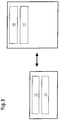
- Fig. 2 shows a schematic block diagram for the on the industrial personal computer 23 realized as software Functions for controlling the palletizing system.
- a first Control components 24 are on the industrial personal computer 23 together the functions of the robot sequence control as well of the control panel.
- the functions of the PLC, however are part of a second control component 25 on the industrial personal computer 23 realized.
- First control component 24 and second control component 25 are on the Industrial personal computer 23 implemented independently of one another.
- the core of the first control component 24 is a robot programming language interpreter, especially an IRL interpreter 26.
- the Industrial Robot Language Interpreter (IRL) implements functions of robot sequence control and of the control panel in software.
- the IRL interpreter has a control panel module 27.
- the functions of the robot sequence control are by a positioning module 28 and a module 29 for additional functions realized. With the help of module 29 for the additional functions
- the palletizing robot 11 can be time-optimized be positioned.
- the second control component 25 is a Real-time platform, which therefore works in real time. part the second control component 25 is a PLC compiler 30, of the functions of the PLC.
- Both the IRL interpreter 26 and the PLC compiler 30 are via files to the palletizing robot 11 to be specifically controlled customizable.
- the PLC compiler is the PLC file 31.
- the IRL interpreter is the files 32, 33.
- File 32 is also referred to as an IRL program file, the file 33, however, as a control panel file.
- First control component 24 and second control component 25 communicate via appropriate software interfaces.
- a PLC task 34 generated by the PLC compiler 30 is executed by a separate PLC module 35 of the IRL interpreter 26 called.
- the PLC task 34 of the second control component 25 and the PLC module 35 of the first control component 24 swap here Data from.
- Another data exchange between the first Control component 24 and the second control component 25 takes place between the positioning module 28 of the first Control component 24 and a positioning task 36 of the second control component 25.
- the module 29 for additional functions of the first control component 24 a suitable interface data to a module 37 of the second Transfer control component 25 back and forth.
- the PLC task 34 With the help of the PLC task 34 generated by the PLC compiler 30 all peripheral components of the palletizing system namely the Gripper 17, the feed table 19 and the tilting device 20 etc. controlled. Furthermore, for example, the emergency stop circuit monitored for the feed table 19 and the gripper 17.
- the PLC task 34 becomes cyclical in an adjustable real-time cycle run through.
- the IRL interpreter generates function calls for PLC task 34 and positioning task 36. Functions of the control panel are as control panel module 27 in the IRL interpreter realized. After each IRL command, the control panel is called.
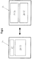
- FIG. 4 shows.
- the PLC functions are always independent of the through functions performed by the IRL interpreter 26.
- the IRL interpreter 26 of the first control component 24 works all IRL commands by the positioning module 28 and the Module 29 for additional functions continuously.
- the positioning task 36 or module 37 the accept the commands generated by the IRL interpreter 26 and real-time control commands for the palletizing robot 11 to generate.
- From the real-time positioning task 36 are the positioning commands via the I / O module (Input / output module) 15 to the motor control 14 of the Palletizing robot 11 handed over.
- the PLC task 34 generates analogously real-time control commands for the gripper 17 of the palletizing robot 11 and for the feed table 19 and the tilting device 20.
- the data transfer takes place via the I / O modules 18, 21 and 22.
- a file 38 which is also referred to as a configuration file, machine data the palletizing system to be controlled including the robot 11, its gripper 17, the feed table 19 and the tilting device 20 set.
- a second A corresponding PLC program is written in the step in the PLC file 31.
- the files 31, 38 are therefore used for configuration the second control component 25, which operates in real time.
- the file 32 namely in an appropriate IRL program is created for the IRL program file. Only after this is a fourth step in the File 33 made a configuration for the control panel.
- the Machine data set in the file 38 for the machine to be controlled Palletizing robot 11 and the peripheral components of the Plant will be the second via a suitable interface Control component 25 passed and in a corresponding Module 39 of the same ready for further processing.
- the adaptation of the control system to that of the one to be controlled Palletizing robots 11 packing patterns to be handled are usually carried out via a third control component 40 it is preferably an external personal computer.
- the third control component 40 includes one from the end user freely programmable palletizing system 41, with the help of it a file 42 for packing patterns can be generated.
- the third Control component is an external PC with an off-line palletizing system.
- the file 42 for the packing pattern is from a data memory assigned to the IRL interpreter 26 43 read. Since the IRL interpreter 26 as before shown several times on an industrial personal computer is realized, the data memory 43 has a very large capacity, so that almost any number of Files 42 for packing patterns are stored and processed can.
- file 42 in the teach process to generate directly on the IRL interpreter 26.
- Fig. 2 block diagram shown is for one by its nature Operating system not capable of multitasking (e.g. DOS) or a Single-task operating system designed. From targeting such a single-task operating system results in a monolithic Structure of the software with limited changeability and scalability of the software in terms of certain Conditions.
- Operating system not capable of multitasking e.g. DOS
- Single-task operating system designed From targeting such a single-task operating system results in a monolithic Structure of the software with limited changeability and scalability of the software in terms of certain Conditions.
- the first control component 24 according to FIG. 2 is in FIG. 5 divided into an interpreter module 26 together with a module for additional functions 29, positioning module 28 and PLC module 35, and a Robot control module 44.
- COM Component Object Model
- the control module 44 is designed as a tool for technicians, which retract or put the machine into operation. It is used to display user output and program errors. These tasks are performed according to the single task based system Fig. 2 executed by the IRL module.
- the evaluation or preprocessing of the from IRL module 26 sent motion commands made on what the single-task-based system according to FIG. 2 in the second Control component 25 takes place. This evaluation of the movement commands is used to prepare for movement and is used as Control module 44 arranged block 44a shown the data receives via the interface 46.
- the one in the control module Block 44b arranged 44 represents a user interface represents the data between control module 44 and interface 46 exchanges.
- a block 44c is also in the control module 44 integrated, which represents a PLC module that data the PLC task 34 is transmitted.
- the robot control module 44 is also the only module (next to the visualization module or control panel 47) that with communicates with a real-time task. Acting in the real-time task z. B. the positioning task 36 or the PLC task 34.
- the visualization module or control panel 47 also runs independently Program. This makes you not like single-task based Control, to a specific, specially coordinated Control panel software instructed. Rather you can on use any (standard) program packages.
- the visualization module or control panel 47 receives configuration data from a file 33. It is contrary to that shown in Fig. 2 System detached from the first control component 24 as fourth control component realizes and communicates with the first control component 24 via the software interface 46.
- Real-time software is used for the multi-task-based Rotoberober Entry used. It is possible to have several PLC tasks to run in parallel. Due to the opposite of that in FIG. 2 shown modified structure of the real-time software results the possibility of the structure of that shown in Fig. 2 Position module to change.
- 6 module shown for the multi-task system according to FIG. 5 only in the form of a universally usable basic functionality embedded in the real-time core 48.
- Linear method 49 PTP (point to point) method 50 or other method 51, as additional PLC tasks 52 implemented.
- PTP point to point
- This enables a developer to only without a modification to the real-time core 48 Change a positioning program to a PLC program change and add. Since the positioning of the axes as independent PLC program is running in its own task nevertheless an encapsulation compared to the "normal", for control given the necessary PLC program.
- FIG. 6 also shows a second PLC task 53 for the system control 54.
- This system controller 54 communicates with the Real-time core 48 with real-time module 55.
- control device 13 With increased functionality and Speed of the palletizing robot 11 three previously separate Hardware components replaced. Accordingly, the entire palletizing system programmed from a central control device and be controlled. By using the industrial personal computer 23 stands as control device 13 Furthermore, an almost unlimited storage capacity is available. There can therefore be a large number of files about packing patterns be kept ready. This will make the control system very flexible. Furthermore, it should be noted that the industrial personal computer simply and quickly to the data transmission device 12, especially the fiber optic bus leaves. The wiring effort and commissioning effort of the control system 10 is accordingly small.
Abstract
Description
Die Erfindung betrifft ein Steuerungssystem für Roboter, insbesondere für Palettieranlagen mit Robotern, wobei ein Roboter und Palettieranlagenkomponenten über eine Datenübertragungseinrichtung mit einer Steuerungseinrichtung verbunden sind.The invention relates to a control system for robots, in particular for palletizing systems with robots, one robot and palletizing system components via a data transmission device are connected to a control device.
Steuerungssysteme für insbesondere Palettieranlagen mit Robotern sind hinlänglich bekannt. Bei bekannten Steuerungssystemen besteht die Steuerungseinrichtung aus drei unterschiedlichen Baugruppen, nämlich einem Roboterablaufsteuerungssystem, einer SPS-Einheit sowie einem externen Bedienpult. Die Verknüpfung dieser drei Baugruppen untereinander sowie die Anbindung derselben an eine Datenübertragungseinrichtung erfordert einen großen Aufwand sowie Personaleinsatz, da die drei obigen Baugruppen auf der Hardwareseite umständlich miteinander verdrahtet werden müssen. Der ständige Datenaustausch zwischen diesen drei Baugruppen (Hardware) ist zudem sehr zeitaufwendig und begrenzt damit die Leistungsfähigkeit der Palettier-Anlage. Des weiteren ist von Nachteil, daß unterschiedliche Baugruppen sowie Programmiersprachen für diese Baugruppen beherrscht und gepflegt werden müssen. Des weiteren ist bei den bekannten Steuerungssystemen von Nachteil, daß infolge ihres begrenzten Speicherplatzes nur eine geringe Anzahl von durch den zu steuernden Robotern handzuhabenden Packmustern verarbeitet werden können. Bekannte Steuerungssysteme für Palettieranlagen erfordern demnach einen großen Aufwand bei Inbetriebnahme, Pflege und Wartung und sind des weiteren infolge des begrenzten Speicherplatzes insgesamt unflexibel.Control systems for in particular palletizing systems with robots are well known. In known control systems the control device consists of three different ones Assemblies, namely a robot sequence control system, one PLC unit and an external control panel. The link of these three modules with each other and the connection of the same to a data transmission device requires one great effort as well as human resources, because the three assemblies above laboriously wired together on the hardware side Need to become. The constant data exchange between them three modules (hardware) is also very time consuming and limited thus the performance of the palletizing system. Of Another disadvantage is that different assemblies as well Mastered and maintained programming languages for these modules Need to become. Furthermore, the known control systems disadvantageous that due to their limited storage space only a small number of to be controlled by the Packing patterns that can be handled by robots can be processed. Known control systems for palletizing systems therefore require a lot of effort in commissioning, care and maintenance and are further due to the limited storage space overall inflexible.
Hiervon ausgehend liegt der vorliegenden Erfindung das Problem zugrunde, ein mit geringem Aufwand inbetriebnehmbares, wartbares sowie pflegbares Steuerungssystem bereitzustellen, das des weiteren eine erhöhte Flexibilität hinsichtlich der Anzahl der zu verarbeitenden Packmuster aufweist.Proceeding from this, the present invention has the problem the basis, a maintainable with little effort as well as maintainable control system that furthermore increased flexibility with regard to the number of the packing samples to be processed.
Zur Lösung dieses Problems ist das erfindungsgemäße Steuerungssystem dadurch gekennzeichnet, daß die Steuerungseinrichtung als ein Mikroprozessorsystem, insbesondere als ein Industrie-Personalcomputer, ausgebildet ist, wobei das Mikroprozessorsystem sämtliche Steuerungseinrichtungs-Funktionen, insbesondere Funktionen einer Roboterablaufsteuerung, einer SPS und eines Bedienpults, zur Steuerung der Palettieranlagen realisiert.The control system according to the invention is used to solve this problem characterized in that the control device as a microprocessor system, especially as an industrial personal computer, is formed, the microprocessor system all control device functions, in particular Functions of a robot sequence control, a PLC and one Control panels, implemented to control the palletizing systems.
Durch die Verwendung eines ungeteilten Mikroprozessorsystems als Steuerungseinrichtung wird der Speicherplatz des Steuerungssystems erheblich vergrößert, weil die Speicherkapazität nicht durch die endliche Speichergröße einzelner Hardwarebaugruppen eingeschränkt wird. Es können demnach eine nahezu beliebige Anzahl von Packmustern verarbeitet werden. Hierdurch erhöht sich die Flexibilität des Steuerungssystems. Da des weiteren das Mikroprozessorsystem sämtliche Steuerungseinrichtungs-Funktionen, insbesondere die Funktionen der Roboterablaufsteuerung, der SPS und des Bedienpults, softwaremäßig realisiert, muß nur noch lediglich eine Baugruppe, nämlich das Mikroprozessorsystem, mit der Datenübertragungseinrichtung verdrahtet werden. Hierdurch ist das Steuerungssystem mit geringerem Aufwand inbetriebnehmbar, wartbar sowie pflegbar.By using an undivided microprocessor system the storage space of the control system becomes the control device significantly increased because of the storage capacity not due to the finite memory size of individual hardware modules is restricted. It can therefore be almost any number of packing samples can be processed. Hereby increases the flexibility of the control system. There furthermore the microprocessor system all control device functions, in particular the functions of the robot sequence control, the PLC and the control panel, in software realized, only needs one assembly, namely that Microprocessor system, wired to the data transmission device become. As a result, the control system is less Effort can be put into operation, maintained and maintained.
Vorzugsweise sind die Funktionen der Roboterablaufsteuerung und des Bedienpults gemeinsam als eine erste Steuerungskomponente auf dem Mikroprozessorsystem softwaremäßig realisiert. Die Funktionen der SPS sind als Teil einer zweiten Steuerungskomponente ebenfalls auf dem Mikroprozessorsystem softwaremäßig realisiert. Hieraus folgt, daß auf dem Mikroprozessorsystem lediglich zwei als Software realisierte Steuerungskomponenten beherrscht und gepflegt werden müssen. Auch hierdurch vereinfacht sich die Inbetriebnahme, die Pflege und die Wartung des Steuerungssystems erheblich.The functions of the robot sequence control and are preferably the control panel together as a first control component implemented in software on the microprocessor system. The PLC functions are part of a second control component also implemented in software on the microprocessor system. It follows that on the microprocessor system only mastered two control components implemented as software and need to be taken care of. This also simplifies this the commissioning, care and maintenance of the control system considerably.
Bevorzugte Weiterbildungen der Erfindung ergeben sich aus den Unteransprüchen und der Beschreibung. Anhand der Zeichnung wird ein Ausführungsbeispiel der Erfindung näher erläutert. In der Zeichnung zeigen:
- Fig. 1
- eine schematisierte Darstellung einer Palettier-Anlage aus Steuerungseinrichtung, Palettier-Roboter mit Greifer sowie Zuführtisch mit Kippeinrichtung,
- Fig. 2
- ein schematisiertes Blockschaltbild eines Steuerungssystems für die Palettier-Anlage, inklusive des Palettier-Roboters,
- Fig. 3
- ein schematisiertes Blockdiagramm für die Konfiguration des Steuerungssystems,
- Fig. 4
- ein schematisiertes Blockdiagramm für das Laufzeitverhalten des Steuerungssystems,
- Fig. 5
- ein weiteres schematisiertes Blockschaltbild eines Steuerungssystems für die Palettier-Anlage, inklusive des Palettier-Roboters, und
- Fig. 6
- ein schematisiertes Blockschaltbild zweier SPS-Tasks sowie eines Echtzeitkerns.
- Fig. 1
- 1 shows a schematic representation of a palletizing system comprising a control device, a palletizing robot with a gripper and a feed table with a tilting device,
- Fig. 2
- 1 shows a schematic block diagram of a control system for the palletizing system, including the palletizing robot,
- Fig. 3
- 1 shows a schematic block diagram for the configuration of the control system,
- Fig. 4
- 1 shows a schematic block diagram for the runtime behavior of the control system,
- Fig. 5
- another schematic block diagram of a control system for the palletizing system, including the palletizing robot, and
- Fig. 6
- a schematic block diagram of two PLC tasks and a real-time kernel.
Fig. 1 zeigt schematisiert das Hardware-Konzept eines Steuerungssystems
10 für eine Palettieranlage mit Roboter, wie beispielsweise
in US 5 348 440 sowie US 5 232 332 beschrieben. Der
Palettier-Roboter 11 ist über eine Datenübertragungseinrichtung
12 mit einer Steuerungseinrichtung 13 verbunden. Gemäß Fig. 1
ist hierzu der Palettier-Roboter 11, nämlich dessen Motoransteuerung
14, über ein I/O-Modul (Input/Output-Modul) 15 an der
Datenübertragungseinrichtung 12 gekoppelt. Die Steuerungseinrichtung
13 ist ihrerseits ebenfalls über ein I/O-Modul 16 an
der Datenübertragungseinrichtung 12 gekoppelt. Neben der Motoransteuerung
14 des Palettier-Roboters 11 ist auch ein Greifer
17 des Palettier-Roboters 11 über ein entsprechendes I/O-Modul
18 an der Datenübertragungseinrichtung 12 gekoppelt. Zusätzlich
zur Motoransteuerung 14 und zum Greifer 17 des Palettier-Roboters
11 hängen auch ein Zuführtisch 19 für vom Palettier-Roboter
handzuhabende Packmuster sowie eine auf dem Zuführtisch
19 montierte Kippeinrichtung 20 über entsprechende I/O-Module
21, 22 an der Datenübertragungseinrichtung 12. Auf gleiche Weise
können auch weitere Komponenten der Palettieranlage wie zum
Beispiel Palettenförderer, Palettenhubtische angekoppelt werden.
Die Datenübertragungseinrichtung 12 ist bevorzugt als
Lichtwellenleiter-Bussystem (LWL-Bus) ausgebildet.1 schematically shows the hardware concept of a
Die Steuerungseinrichtung 13 des Steuerungssystems 10 ist erfindungsgemäß
als Mikroprozessorsystem, nämlich als ein Industrie-Personalcomputer
23, ausgebildet. Der Industrie-Personalcomputer
23 realisiert sämtliche Steuerungseinrichtungs-Funktionen
zur Steuerung der Palettieranlage mit dem Palettier-Roboter
11. Hierzu gehören Funktionen einer Roboterablaufsteuerung,
einer speicherprogrammierbaren Steuerung (SPS) und
eines Bedienpults. Diese Funktionen sind auf dem Industrie-Personalcomputer
23 allesamt softwaremäßig realisiert. Bei dem erfindungsgemäßen
Steuerungssystem 10 muß demnach zur Steuerung
der Palettieranlage lediglich der Industrie-Personalcomputer 23
als Steuerungseinrichtung 13 an die Datenübertragungseinrichtung
12 angekoppelt werden. Dies ist mit geringem
Verdrahtungsaufwand möglich. Der Industrie-Personalcomputer
23 ersetzt die bei bislang bekannten Steuerungssystemen erforderlichen
drei separaten Baugruppen Roboterablaufsteuerung,
SPS-Einheit sowie externes Bedienpult.The
Fig. 2 zeigt ein schematisiertes Blockschaltbild für die auf
dem Industrie-Personalcomputer 23 als Software realisierten
Funktionen zur Steuerung der Palettieranlage. Als eine erste
Steuerungskomponente 24 sind auf dem Industrie-Personalcomputer
23 gemeinsam die Funktionen der Roboterablaufsteuerung sowie
des Bedienpults realisiert. Die Funktionen der SPS hingegen
sind als Teil einer zweiten Steuerungskomponente 25 auf dem Industrie-Personalcomputer
23 realisiert. Erste Steuerungskomponente
24 sowie zweite Steuerungskomponente 25 sind auf dem
Industrie-Personalcomputer 23 unabhängig voneinander realisiert.Fig. 2 shows a schematic block diagram for the on
the industrial
Kernstück der ersten Steuerungskomponente 24 ist ein Roboterprogrammiersprache-Interpreter,
insbesondere ein IRL-Interpreter
26. Der IRL-Interpreter (Industrial Robot Language-Interpreter)
realisiert Funktionen der Roboterablaufsteuerung und
des Bedienpults softwaremäßig. Zur Realisierung der Bedienpult-Funktionen
verfügt der IRL-Interpreter über ein Bedienpult-Modul
27. Die Funktionen der Roboterablaufsteuerung werden
durch ein Positionierungsmodul 28 sowie ein Modul 29 für Zusatzfunktionen
realisiert. Mit Hilfe des Moduls 29 für die Zusatzfunktionen
kann zum Beispiel der Palettier-Roboter 11 zeitoptimiert
positioniert werden.The core of the
Bei der zweiten Steuerungskomponente 25 handelt es sich um eine
Echtzeitplattform, die demnach im Echtzeittakt arbeitet. Teil
der zweiten Steuerungskomponente 25 ist ein SPS-Compiler 30,
der Funktionen der SPS realisiert.The
Sowohl der IRL-Interpreter 26 als auch der SPS-Compiler 30 sind
über Dateien an den konkret zu steuernden Palettier-Roboter 11
anpaßbar. Beim SPS-Compiler handelt es sich hierbei um die SPS-Datei
31. Beim IRL-Interpreter handelt es sich um die Dateien
32, 33. Die Datei 32 wird auch als IRL-Programmdatei bezeichnet,
die Datei 33 hingegen als Bedienpultdatei.Both the
Erste Steuerungskomponente 24 sowie zweite Steuerungskomponente
25 kommunizieren über entsprechende Software-Schnittstellen.
Eine vom SPS-Compiler 30 erzeugte SPS-Task 34 wird von einem
separaten SPS-Modul 35 des IRL-Interpreters 26 aufgerufen. Die
SPS-Task 34 der zweiten Steuerungskomponente 25 sowie das SPS-Modul
35 der ersten Steuerungskomponente 24 tauschen hierbei
Daten aus. Ein weiterer Datenaustausch zwischen der ersten
Steuerungskomponente 24 sowie der zweiten Steuerungskomponente
25 erfolgt zwischen dem Positionierungs-Modul 28 der ersten
Steuerungskomponente 24 und einer Positionierungs-Task 36 der
zweiten Steuerungskomponente 25. Des weiteren werden vom Modul
29 für Zusatzfunktionen der ersten Steuerungskomponente 24 über
eine geeignete Schnittstelle Daten an ein Modul 37 der zweiten
Steuerungskomponente 25 hin- und herübertragen.
Mit Hilfe der vom SPS-Compiler 30 erzeugten SPS-Task 34 werden
sämtliche Peripheriekomponenten der Palettieranlage nämlich der
Greifer 17, der Zuführtisch 19 sowie die Kippeinrichtung 20
etc. gesteuert. Des weiteren wird zum Beispiel der Notauskreis
für den Zuführtisch 19 sowie den Greifer 17 überwacht. Die SPS-Task
34 wird hierbei zyklisch in einem einstellbaren Echtzeittakt
durchlaufen. Der IRL-Interpreter 26 hingegen realisiert
unter anderem die Roboterablaufsteuerung. Im Gegensatz zum SPS-Compiler
30 arbeitet der IRL-Interpreter 26 nicht im Echtzeittakt.
Auch finden beim IRL-Interpreter 26 keine zyklischen Wiederholungen
statt. Der IRL-Interpreter erzeugt Funktionsaufrufe
für die SPS-Task 34 sowie die Positionierungs-Task 36. Funktionen
des Bedienpults sind als Bedienpult-Modul 27 im IRL-Interpreter
realisiert. Nach jedem IRL-Befehl wird das Bedienpult
aufgerufen.With the help of the
Das Laufzeitverhalten des erfindungsgemäßen Steuerungssystems
zeigt Fig. 4. Im Zusammenhang mit Fig. 4 sei nochmals angemerkt,
daß die SPS-Funktionen stets unabhängig von den durch
den IRL-Interpreter 26 realisierten Funktionen ablaufen. Der
IRL-Interpreter 26 der ersten Steuerungskomponente 24 arbeitet
alle IRL-Befehle durch das Positionierungs-Modul 28 sowie das
Modul 29 für Zusatzfunktionen kontinuierlich ab. Hierbei wird
die Positionierungs-Task 36 bzw. das Modul 37 aufgerufen, die
die vom IRL-Interpreter 26 erzeugten Befehle übernehmen und
echtzeitfähige Steuerungsbefehle für den Palettier-Roboter 11
generieren. Von der im Echtzeitmodus arbeitenden Positionierungs-Task
36 werden die Positionierungsbefehle über das I/O-Modul
(Input/Output-Modul) 15 an die Motoransteuerung 14 des
Palettier-Roboters 11 übergeben. Analog erzeugt die SPS-Task 34
echtzeitfähige Steuerungsbefehle für den Greifer 17 des Palettier-Roboters
11 sowie für den Zuführtisch 19 und die Kippeinrichtung
20. Die Datenübertragung erfolgt über die I/O-Module
18, 21 sowie 22.The runtime behavior of the control system according to the invention
FIG. 4 shows. In connection with FIG.
that the PLC functions are always independent of the through
functions performed by the
Bei der Konfiguration des Steuerungssystems wird gemäß Fig. 3
vorgegangen. In einem ersten Schritt werden in einer Datei 38,
die auch als Konfigurations-Datei bezeichnet wird, Maschinendaten
der zu steuernden Palettieranlage inklusive des Roboters
11, seines Greifers 17, des Zuführtischs 19 sowie der Kippeinrichtung
20 eingestellt. Darauffolgend wird in einem zweiten
Schritt in der SPS-Datei 31 ein entsprechendes SPS-Programm geschrieben.
Die Dateien 31, 38 dienen demnach der Konfiguration
der zweiten Steuerungskomponente 25, die im Echtzeittakt arbeitet.
In einem dritten Schritt wird in der Datei 32, nämlich in
der IRL-Programmdatei ein entsprechendes IRL-Programm erstellt.
Erst im Anschluß hieran wird in einem vierten Schritt in der
Datei 33 eine Konfiguration für das Bedienpult vorgenommen. Die
in der Datei 38 eingestellten Maschinendaten für den zu steuernden
Palettier-Roboter 11 sowie die Peripheriekomponenten der
Anlage werden über eine geeignete Schnittstelle der zweiten
Steuerungskomponente 25 übergeben und in einem entsprechenden
Modul 39 derselben zur Weiterverarbeitung bereitgehalten.In the configuration of the control system, according to FIG. 3
proceeded. In a first step, a
Die Anpassung des Steuerungssystems an die vom zu steuernden
Palettier-Roboter 11 handzuhabenden Packmuster erfolgt üblicherweise
über eine dritte Steuerungskomponente 40. Hierbei
handelt es sich vorzugsweise um einen externen Personalcomputer.
Die dritte Steuerungskomponente 40 umfaßt ein vom Endanwender
frei programmierbares Palettiersystem 41, mit Hilfe dessen
eine Datei 42 für Packmuster erzeugbar ist. Bei der dritten
Steuerungskomponente handelt es sich um einen externen PC mit
einem off-line Palettiersystem. Die Datei 42 für die Packmuster
wird von einem den IRL-Interpreter 26 zugeordneten Datenspeicher
43 eingelesen. Da der IRL-Interpreter 26 wie bereits
mehrfach dargestellt auf einem Industrie-Personalcomputer
realisiert ist, verfügt der Datenspeicher 43 über eine sehr
große Kapazität, so daß nahezu eine beliebig große Anzahl von
Dateien 42 für Packmuster gespeichert und verarbeitet werden
kann.The adaptation of the control system to that of the one to be controlled
Alternativ ist es jedoch auch möglich, die Datei 42 im Teach-Verfahren
direkt am IRL-Interpreter 26 zu erzeugen.Alternatively, however, it is also possible to use
Die bisher beschriebene Robotersteuerung, insbesondere das in Fig. 2 gezeigte Blockschaltbild, ist für ein seiner Natur nach nicht multitaskingfähiges Betriebssystem (z. B. DOS) bzw. ein Single-Task-Betriebssystem ausgelegt. Aus der Ausrichtung auf ein derartiges Single-Task-Betriebssystem ergibt sich eine monolithische Struktur der Software mit eingeschränkter Veränderbarkeit und Skalierbarkeit der Software im Hinblick auf bestimmte Anforderungen.The robot control described so far, in particular that in Fig. 2 block diagram shown is for one by its nature Operating system not capable of multitasking (e.g. DOS) or a Single-task operating system designed. From targeting such a single-task operating system results in a monolithic Structure of the software with limited changeability and scalability of the software in terms of certain Conditions.
Fig. 5 beschreibt daher eine Robotersteuerung für ein multitaskingfähiges
Betriebssystem, wie zum Beispiel Windows-NT. Ein
derartiges multitaskingfähiges Betriebssystem ermöglicht einen
wesentlich modulareren Aufbau der Software. Die untere, durch
eine gestrichelte Linie abgeteilte Hälfte 25 entspricht dem in
Fig. 2 als zweite Steuerungskomponente 25 beschriebenen Block,
soweit nachfolgend nichts anderes erläutert ist.5 therefore describes a robot controller for a multitasking capable
Operating system, such as Windows NT. A
Such a multitasking operating system enables one
much more modular structure of the software. The lower one, by
a
Die erste Steuerungskomponente 24 gemäß Fig. 2 ist in Fig. 5
aufgeteilt in ein Interpretermodul 26 nebst Modul für Zusatzfunktionen
29, Positioniermodul 28 und SPS-Modul 35, sowie ein
Roboter-Steuerungsmodul 44. Der Interpreter 26 dient nur zur
Abarbeitung der IRL-Programme und besitzt keinerlei Bedienfunktionen.
Statt dessen enthält das Interpretermodul 26 nebst Zusatzmodulen
28, 29 und 35 eine standardisierte Software-Schnittstelle
46, z. B. gemäß dem COM-Standard (COM = Component
Object Model), zur Kommunikation mit anderen Programmen. Über
diese Schnittstelle 46 werden Bewegungsbefehle, Benutzerausgaben
etc. gesendet. Durch die Verwendung dieser standardisierten
Software-Schnittstelle 46 kann man problemlos unabhängige
Steuerungskomponenten dem Steuerungssystem hinzufügen. Dadurch
läßt sich das System nahezu beliebig erweitern.The
Das Steuerungsmodul 44 ist als Werkzeug für Techniker konzipiert,
welche die Maschine einfahren bzw. in Betrieb nehmen. Es
dient zur Anzeige von Benutzerausgaben und Programmfehlern.
Diese Aufgaben werden beim Single-Task-basierten System gemäß
Fig. 2 vom IRL-Modul ausgeführt. Außerdem wird im Steuerungsmodul
44 gemäß Fig. 5 die Auswertung bzw. Vorverarbeitung der vom
IRL-Modul 26 gesendeten Bewegungsbefehle vorgenommen, was auf
dem Single-Task-basierten System gemäß Fig. 2 in der zweiten
Steuerungskomponente 25 erfolgt. Diese Auswertung der Bewegungsbefehle
dient der Bewegungsvorbereitung und ist als im
Steuerungsmodul 44 angeordneter Block 44a dargestellt, der Daten
über die Schnittstelle 46 erhält. Der ebenfalls im Steuerungsmodul
44 angeordnete Block 44b stellt eine Benutzeroberfläche
dar, die Daten zwischen Steuerungsmodul 44 und Schnittstelle
46 austauscht. Ferner ist ein Block 44c im Steuerungsmodul
44 integriert, der ein SPS-Modul darstellt, das Daten an
die SPS-Task 34 übermittelt.The control module 44 is designed as a tool for technicians,
which retract or put the machine into operation. It
is used to display user output and program errors.
These tasks are performed according to the single task based system
Fig. 2 executed by the IRL module. In addition, in the control module
44 the evaluation or preprocessing of the from
Das Roboter-Steuerungsmodul 44 ist außerdem das einzige Modul
(neben dem Visualisierungsmodul bzw. Bedienpult 47), das mit
einer Echtzeit-Task kommuniziert. Bei der Echtzeit-Task handelt
es sich z. B. um die Positionierungs-Task 36 bzw. die SPS-Task
34.The robot control module 44 is also the only module
(next to the visualization module or control panel 47) that with
communicates with a real-time task. Acting in the real-time task
z. B. the
Auch das Visualisierungsmodul bzw. Bedienpult 47 läuft als eigenständiges
Programm. Dadurch ist man nicht, wie bei der Single-Task-basierten
Steuerung, auf eine bestimmte, speziell abgestimmte
Bedienpultsoftware angewiesen. Vielmehr kann man auf
beliebige (Standard-)Programmpakete zurückgreifen. Das Visualisierungsmodul
bzw. Bedienpult 47 erhält aus einer Datei 33 Konfigurationsdaten.
Es ist entgegen dem in Fig. 2 dargestellten
System losgelöst von der ersten Steuerungskomponente 24 als
vierte Steuerungskomponente realisiert und kommuniziert mit der
ersten Steuerungskomponente 24 über die Software-Schnittstelle
46.The visualization module or
Für die Multi-Task-basierte Rotobersteuerung wird eine Echtzeitsoftware
verwendet. Dabei ist es möglich, mehrere SPS-Tasks
parallel laufen zu lassen. Durch die gegenüber der in Fig. 2
dargestellten geänderten Struktur der Echtzeitsoftware ergibt
sich die Möglichkeit, die Struktur des in Fig. 2 dargestellten
Positionierungs-Moduls zu ändern. Während das Positionierungs-Modul
28 beim in Fig. 2 dargestellten Single-Task-System in den
Echtzeitkern eingebettet und nur durch ein Verändern und Neuerzeugen
der gesamten Echtzeitsoftware zu ändern ist, wird das in
Fig. 6 dargestellte Modul für das Multi-Task-System gemäß Fig.
5 nur in Form einer universell verwendbaren Basisfunktionalität
in den Echtzeitkern 48 eingebettet. Dabei werden die Funktionalitäten
für eine bestimmte Art des Verfahrens (bzw. Bewegens)
der Roboterachsen, z. B. Linearverfahren 49, PTP (point to
point)-Verfahren 50 oder anderer Verfahren 51, als zusätzliche
SPS-Tasks 52 realisiert. Dadurch hat ein Entwickler die Möglichkeit,
ohne eine Modifikation am Echtzeitkern 48 nur durch
Ändern eines SPS-Programms die Positionier-Funktionalitäten zu
verändern und zu ergänzen. Da die Positionierung der Achsen als
eigenständiges SPS-Programm in einer eigenen Task läuft, ist
trotzdem eine Kapselung gegenüber dem "normalen", zur Steuerung
der Anlage erforderlichen SPS-Programm gegeben.Real-time software is used for the multi-task-based Rotoberoberführung
used. It is possible to have several PLC tasks
to run in parallel. Due to the opposite of that in FIG. 2
shown modified structure of the real-time software results
the possibility of the structure of that shown in Fig. 2
Position module to change. During the
Ferner zeigt Fig. 6 eine zweite SPS-Task 53 für die Anlagensteuerung
54. Diese Anlagensteuerung 54 kommuniziert mit dem
Echtzeitkern 48 und zwar mit dem Echtzeitmodul 55.6 also shows a
Gegenüber dem System gemäß Fig. 2 hat das in den Fig. 5 und 6
dargestellte System insbesondere den Vorteil, daß die SPS-Tasks
52, 53 nicht unmittelbar im Echtzeitkern 55 laufen. Dadurch
braucht bei Änderungen der SPS-Tasks 52, 53 nicht zusätzlich
der Echtzeitkern verändert zu werden. Auf diese Weise kann man
die Zahl möglicher Fehlerquellen reduzieren.Compared to the system according to FIG. 2, this has in FIGS. 5 and 6
System shown has the particular advantage that the
Die Vorteile des neuen Steuerungssystems liegen auf der Hand.
Durch die Verwendung des Industrie-Personalcomputers 23 als
Steuerungseinrichtung 13 werden bei erhöhter Funktionalität und
Geschwindigkeit des Palettier-Roboters 11 drei bislang separate
Hardwarekomponenten ersetzt. Demnach kann die gesamte Palettier-Anlage
von einer zentralen Steuerungseinrichtung aus programmiert
und gesteuert werden. Durch die Verwendung des Industrie-Personalcomputers
23 als Steuerungseinrichtung 13 steht
des weiteren eine nahezu unbegrenzte Speicherkapazität zur Verfügung.
Es können daher eine Vielzahl von Dateien über Packmuster
bereitgehalten werden. Hierdurch wird das Steuerungssystem
sehr flexibel. Des weiteren sei angemerkt, daß sich der Industrie-Personalcomputer
einfach und schnell an die Datenübertragungseinrichtung
12, insbesondere den LWL-Bus ankoppeln
läßt. Der Verdrahtungsaufwand sowie Inbetriebnahmeaufwand
des Steuerungssystems 10 ist demnach gering. The advantages of the new control system are obvious.
By using the industrial
- 1010th
- SteuerungssystemControl system
- 1111
- Palettier-RoboterPalletizing robot
- 1212th
- DatenübertragungseinrichtungData transmission device
- 1313
- SteuerungseinrichtungControl device
- 1414
- MotoransteuerungMotor control
- 1515
- I/O-ModulI / O module
- 1616
- I/O-ModulI / O module
- 1717th
- GreiferGripper
- 1818th
- I/O-ModulI / O module
- 1919th
- ZuführtischFeed table
- 2020th
- KippeinrichtungTilting device
- 2121
- I/O-ModulI / O module
- 2222
- I/O-ModulI / O module
- 2323
- Industrie-PersonalcomputerIndustrial personal computer
- 2424th
- SteuerungskomponenteControl component
- 2525th
- SteuerungskomponenteControl component
- 2626
- IRL-InterpreterIRL interpreter
- 2727
- Bedienpult-ModulControl panel module
- 2828
- Positionierungs-ModulPositioning module
- 2929
- Modulmodule
- 3030th
- SPS-CompilerPLC compiler
- 3131
- Dateifile
- 3232
- Dateifile
- 3333
- Dateifile
- 3434
- SPS-TaskPLC task
- 3535
- SPS-ModulPLC module
- 3636
- Positionierungs-TaskPositioning task
- 3737
- Modulmodule
- 3838
- Dateifile
- 3939
- Modul module
- 4040
- SteuerungskomponenteControl component
- 4141
- PalettiersystemPalletizing system
- 4242
- Dateifile
- 4343
- DatenspeicherData storage
- 4444
- SteuerungsmodulControl module
- 44a44a
- BewegungsvorbereitungPreparation for movement
- 44b44b
- Benutzeroberflächeuser interface
- 44c44c
- SPS-ModulPLC module
- 4646
- standardisierte Software-Schnittstellestandardized Software interface
- 4747
- Visualisierungsmodul bzw. BedienpultVisualization module or control panel
- 4848
- EchtzeitkernReal-time core
- 4949
- LinearverfahrenLinear process
- 5050
- PTP-VerfahrenPTP process
- 5151
- anderes Verfahrenother procedure
- 5252
- SPS-TaskPLC task
- 5353
- SPS-TaskPLC task
- 5454
- AnlagensteuerungPlant control
- 5555
- EchtzeitmodulReal-time module
Claims (12)
Applications Claiming Priority (2)
| Application Number | Priority Date | Filing Date | Title |
|---|---|---|---|
| DE19740775 | 1997-09-17 | ||
| DE19740775A DE19740775A1 (en) | 1997-09-17 | 1997-09-17 | Control system for especially palletizing systems with robots |
Publications (3)
| Publication Number | Publication Date |
|---|---|
| EP0903654A2 true EP0903654A2 (en) | 1999-03-24 |
| EP0903654A3 EP0903654A3 (en) | 2000-08-30 |
| EP0903654B1 EP0903654B1 (en) | 2004-11-24 |
Family
ID=7842564
Family Applications (1)
| Application Number | Title | Priority Date | Filing Date |
|---|---|---|---|
| EP98116930A Expired - Lifetime EP0903654B1 (en) | 1997-09-17 | 1998-09-08 | Control system for a palletisation installation |
Country Status (6)
| Country | Link |
|---|---|
| EP (1) | EP0903654B1 (en) |
| JP (1) | JPH11165285A (en) |
| KR (1) | KR19990029847A (en) |
| CN (1) | CN1070103C (en) |
| BR (1) | BR9803464A (en) |
| DE (2) | DE19740775A1 (en) |
Cited By (4)
| Publication number | Priority date | Publication date | Assignee | Title |
|---|---|---|---|---|
| WO2003023527A2 (en) * | 2001-09-12 | 2003-03-20 | Rexroth Indramat Gmbh | Method for controlling and/or regulating industrial processes |
| EP1400882A2 (en) * | 2002-09-20 | 2004-03-24 | Siemens Aktiengesellschaft | Device for automation and/or control of machine tools or production machines |
| US7035710B2 (en) | 2003-02-06 | 2006-04-25 | Siemens Aktiengesellschaft | Device for automating and/or controlling of machine tools or production machines |
| EP1906284A1 (en) * | 2006-09-28 | 2008-04-02 | Abb Ab | A control device for controlling an industrial robot |
Families Citing this family (8)
| Publication number | Priority date | Publication date | Assignee | Title |
|---|---|---|---|---|
| DE10021838A1 (en) | 2000-05-05 | 2001-11-08 | Focke & Co | Device for manufacturing products and method for controlling such a device |
| DE10307332A1 (en) * | 2003-02-17 | 2004-09-02 | Siemens Ag | Electrical automation device and method for setting the functions of the electrical automation device |
| KR100919115B1 (en) * | 2007-10-31 | 2009-09-25 | 한국기계연구원 | Robot Controller |
| EP2711142B1 (en) * | 2012-09-20 | 2014-09-17 | Comau S.p.A. | Industrial robot having electronic drive devices distributed on the robot structure |
| CN103358309B (en) * | 2013-07-12 | 2016-06-08 | 杭州金人自动控制设备有限公司 | A kind of robot movement Controlling System based on Ethernet |
| RU2578759C2 (en) * | 2013-09-06 | 2016-03-27 | Общество С Ограниченной Ответственностью "Кибернетические Технологии" | Control device in cyber-physical systems, primarily for controlling mobile robots and/or unmanned aerial vehicles |
| CN104786221B (en) * | 2015-04-13 | 2016-12-07 | 浙江工业大学 | A kind of open method for controlling robot based on Ethernet |
| KR101969727B1 (en) * | 2017-10-24 | 2019-04-17 | 주식회사 로보스타 | Apparatus for manipulating multi-joint robot and method thereof |
Citations (3)
| Publication number | Priority date | Publication date | Assignee | Title |
|---|---|---|---|---|
| US4978274A (en) * | 1985-09-16 | 1990-12-18 | R. De Groot Holding Laag-Zuthem B.V. | Manipulator |
| US5032975A (en) * | 1987-08-07 | 1991-07-16 | Canon Kabushiki Kaisha | Controller for automatic assembling apparatus |
| EP0591845A1 (en) * | 1992-10-07 | 1994-04-13 | HK Systems, Inc. | Case picking system |
Family Cites Families (12)
| Publication number | Priority date | Publication date | Assignee | Title |
|---|---|---|---|---|
| JPS60198605A (en) * | 1984-03-22 | 1985-10-08 | Fanuc Ltd | Analog input control system |
| JP2518331B2 (en) * | 1988-01-11 | 1996-07-24 | トヨタ自動車株式会社 | Robot operating time analyzer |
| US5193973A (en) * | 1988-12-31 | 1993-03-16 | System Gmbh | Palletizing system |
| JPH04229308A (en) * | 1990-12-27 | 1992-08-18 | Fanuc Ltd | Instructing method for palletizing |
| JPH04324698A (en) * | 1991-04-24 | 1992-11-13 | Fujitsu Ltd | Irregular-shaped smd mounting machine |
| JP2574983B2 (en) * | 1993-04-06 | 1997-01-22 | 本田技研工業株式会社 | Multitask control system |
| JPH0724665A (en) * | 1993-07-05 | 1995-01-27 | Yamatake Honeywell Co Ltd | Automatic assembly device |
| JPH0811074A (en) * | 1994-06-29 | 1996-01-16 | Fanuc Ltd | Robot system |
| JPH08179807A (en) * | 1994-12-22 | 1996-07-12 | Toppan Printing Co Ltd | Production line managing system |
| JPH0964599A (en) * | 1995-08-22 | 1997-03-07 | Ricoh Co Ltd | Data management system for multi-kinds of products manufacturing system |
| JP3536547B2 (en) * | 1995-09-19 | 2004-06-14 | 三菱電機株式会社 | Monitor system and monitor method |
| EP0800126B1 (en) * | 1995-09-26 | 2002-11-27 | Omron Corporation | Method and apparatus for information processing |
-
1997
- 1997-09-17 DE DE19740775A patent/DE19740775A1/en not_active Withdrawn
-
1998
- 1998-09-08 EP EP98116930A patent/EP0903654B1/en not_active Expired - Lifetime
- 1998-09-08 DE DE59812295T patent/DE59812295D1/en not_active Expired - Lifetime
- 1998-09-16 KR KR1019980038230A patent/KR19990029847A/en not_active Application Discontinuation
- 1998-09-16 BR BR9803464-2A patent/BR9803464A/en not_active Application Discontinuation
- 1998-09-17 CN CN98119278A patent/CN1070103C/en not_active Expired - Fee Related
- 1998-09-17 JP JP10263582A patent/JPH11165285A/en active Pending
Patent Citations (3)
| Publication number | Priority date | Publication date | Assignee | Title |
|---|---|---|---|---|
| US4978274A (en) * | 1985-09-16 | 1990-12-18 | R. De Groot Holding Laag-Zuthem B.V. | Manipulator |
| US5032975A (en) * | 1987-08-07 | 1991-07-16 | Canon Kabushiki Kaisha | Controller for automatic assembling apparatus |
| EP0591845A1 (en) * | 1992-10-07 | 1994-04-13 | HK Systems, Inc. | Case picking system |
Non-Patent Citations (3)
| Title |
|---|
| LIETZ J: "PALETTIEREN MIT INDUSTRIEROBOTERN" , FORDERN UND HEBEN,DE,KRAUSSKOPF VERLAG FUR WIRTSCHAFT. MAINZ, VOL. 41, NR. 12, PAGE(S) 1000-1001 XP000235292 ISSN: 0341-2636 * Abbildung 3 * * |
| PATENT ABSTRACTS OF JAPAN vol. 1996, no. 11, 29. November 1996 (1996-11-29) & JP 08 179807 A (TOPPAN PRINTING CO LTD), 12. Juli 1996 (1996-07-12) * |
| SEVERIN H G: "PALETTIEREN UND DEPALETTIEREN MIT ROBOTERN IN DER DRUCKINDUSTRIE PALLETIZING AND DEPALLETINZING WITH ROBOTS IN THE PRINTING INDUSTRY" , ZWF ZEITSCHRIFT FUR WIRTSCHAFTLICHE FERTIGUNG UND AUTOMATISIERUNG,DE,CARL HANSER VERLAG. MUNCHEN, VOL. 89, NR. 4, PAGE(S) 174-177 XP000441975 ISSN: 0947-0085 * Seite 176 * * |
Cited By (8)
| Publication number | Priority date | Publication date | Assignee | Title |
|---|---|---|---|---|
| WO2003023527A2 (en) * | 2001-09-12 | 2003-03-20 | Rexroth Indramat Gmbh | Method for controlling and/or regulating industrial processes |
| WO2003023527A3 (en) * | 2001-09-12 | 2003-12-24 | Rexroth Indramat Gmbh | Method for controlling and/or regulating industrial processes |
| US7228185B2 (en) | 2001-09-12 | 2007-06-05 | Rexroth Indramat Gmbh | Method for controlling and/or regulating industrial processes |
| EP1400882A2 (en) * | 2002-09-20 | 2004-03-24 | Siemens Aktiengesellschaft | Device for automation and/or control of machine tools or production machines |
| EP1400882A3 (en) * | 2002-09-20 | 2005-08-24 | Siemens Aktiengesellschaft | Device for automation and/or control of machine tools or production machines |
| US7035710B2 (en) | 2003-02-06 | 2006-04-25 | Siemens Aktiengesellschaft | Device for automating and/or controlling of machine tools or production machines |
| EP1906284A1 (en) * | 2006-09-28 | 2008-04-02 | Abb Ab | A control device for controlling an industrial robot |
| WO2008037567A1 (en) * | 2006-09-28 | 2008-04-03 | Abb Ab | A control device for controlling an industrial robot |
Also Published As
| Publication number | Publication date |
|---|---|
| EP0903654A3 (en) | 2000-08-30 |
| JPH11165285A (en) | 1999-06-22 |
| KR19990029847A (en) | 1999-04-26 |
| DE19740775A1 (en) | 1999-03-18 |
| DE59812295D1 (en) | 2004-12-30 |
| BR9803464A (en) | 1999-11-23 |
| CN1211492A (en) | 1999-03-24 |
| CN1070103C (en) | 2001-08-29 |
| EP0903654B1 (en) | 2004-11-24 |
Similar Documents
| Publication | Publication Date | Title |
|---|---|---|
| EP0875023B1 (en) | Automation device | |
| EP1184758B1 (en) | Method for debugging programs for industrial controllers, especially motion controllers, in the context of flow chart programmation | |
| DE3151752C2 (en) | Method and arrangement for controlling a robot | |
| DE2330054C2 (en) | Device for controlling the movement of a working element of a robot arm | |
| DE4411426B4 (en) | Multi-task control system | |
| DE3806966C2 (en) | ||
| EP0903654B1 (en) | Control system for a palletisation installation | |
| EP1279076A2 (en) | Control method and industrial production installation with web control system | |
| DE102012112900A1 (en) | Numerical control program alignment by robots | |
| WO2002065223A2 (en) | System for controlling and monitoring machines and/or systems with active components belonging to different active groups | |
| EP0553621B1 (en) | Programmable computer control for a machine tool | |
| DE3236320A1 (en) | DEVICE FOR MOVING A TOOL CENTER OF A FUNCTIONAL ELEMENT, IN PARTICULAR A ROBOT ARM | |
| WO2002101596A2 (en) | Method and system for assisting in the planning of manufacturing facilities | |
| DE2338880A1 (en) | METHODS AND DEVICES FOR CONTROLLING THE MOVING PARTS OF A MACHINE TOOL THROUGH A NUMERICAL OUTLINE OR POINT-BY-POINT CONTROL SYSTEM, WHEREAS TWO PARTS OF THE MACHINE INDEPENDENTLY SEPARATE | |
| DE10359251A1 (en) | Device for automation of machine tool- or production-machines, has computing device joined to bus-system for two-way data exchange | |
| EP3132319B1 (en) | Method for operating an automation arrangement | |
| DE3500806C2 (en) | Control for an industrial welding robot | |
| EP1183577B1 (en) | Method for the production of an open-loop control block and said control block | |
| DE10038441B4 (en) | "Flow chart programming for industrial controls, especially motion control" | |
| DE10038439B4 (en) | An apparatus, at least comprising a computer system and an industrial controller, for debugging industrial control programs | |
| DE10125384B4 (en) | Device and method for commissioning and diagnosis of control systems | |
| EP1241568B1 (en) | Method and apparatus for entering variables into the program flow of a data processing system | |
| DE3513713A1 (en) | Method and device for programming a control device | |
| DE112021005212T5 (en) | Numerical control system and method for controlling an industrial machine | |
| DE112022000487T5 (en) | Command generating device and computer program |
Legal Events
| Date | Code | Title | Description |
|---|---|---|---|
| PUAI | Public reference made under article 153(3) epc to a published international application that has entered the european phase |
Free format text: ORIGINAL CODE: 0009012 |
|
| AK | Designated contracting states |
Kind code of ref document: A2 Designated state(s): CH DE FR GB IT LI NL |
|
| AX | Request for extension of the european patent |
Free format text: AL;LT;LV;MK;RO;SI |
|
| PUAL | Search report despatched |
Free format text: ORIGINAL CODE: 0009013 |
|
| AK | Designated contracting states |
Kind code of ref document: A3 Designated state(s): AT BE CH CY DE DK ES FI FR GB GR IE IT LI LU MC NL PT SE |
|
| AX | Request for extension of the european patent |
Free format text: AL;LT;LV;MK;RO;SI |
|
| AKX | Designation fees paid | ||
| 17P | Request for examination filed |
Effective date: 20001124 |
|
| RBV | Designated contracting states (corrected) |
Designated state(s): CH DE FR GB IT LI NL |
|
| 17Q | First examination report despatched |
Effective date: 20030702 |
|
| GRAP | Despatch of communication of intention to grant a patent |
Free format text: ORIGINAL CODE: EPIDOSNIGR1 |
|
| RTI1 | Title (correction) |
Free format text: CONTROL SYSTEM FOR A PALLETISATION INSTALLATION |
|
| RTI1 | Title (correction) |
Free format text: CONTROL SYSTEM FOR A PALLETISATION INSTALLATION |
|
| GRAS | Grant fee paid |
Free format text: ORIGINAL CODE: EPIDOSNIGR3 |
|
| GRAA | (expected) grant |
Free format text: ORIGINAL CODE: 0009210 |
|
| RAP1 | Party data changed (applicant data changed or rights of an application transferred) |
Owner name: FOCKE & CO. (GMBH & CO. KG) |
|
| AK | Designated contracting states |
Kind code of ref document: B1 Designated state(s): CH DE FR GB IT LI NL |
|
| REG | Reference to a national code |
Ref country code: GB Ref legal event code: FG4D Free format text: NOT ENGLISH |
|
| REG | Reference to a national code |
Ref country code: CH Ref legal event code: EP |
|
| REF | Corresponds to: |
Ref document number: 59812295 Country of ref document: DE Date of ref document: 20041230 Kind code of ref document: P |
|
| REG | Reference to a national code |
Ref country code: CH Ref legal event code: NV Representative=s name: R. A. EGLI & CO. PATENTANWAELTE |
|
| GBT | Gb: translation of ep patent filed (gb section 77(6)(a)/1977) |
Effective date: 20041214 |
|
| PLBE | No opposition filed within time limit |
Free format text: ORIGINAL CODE: 0009261 |
|
| STAA | Information on the status of an ep patent application or granted ep patent |
Free format text: STATUS: NO OPPOSITION FILED WITHIN TIME LIMIT |
|
| 26N | No opposition filed |
Effective date: 20050825 |
|
| ET | Fr: translation filed | ||
| PGFP | Annual fee paid to national office [announced via postgrant information from national office to epo] |
Ref country code: CH Payment date: 20110913 Year of fee payment: 14 |
|
| PGFP | Annual fee paid to national office [announced via postgrant information from national office to epo] |
Ref country code: FR Payment date: 20110922 Year of fee payment: 14 |
|
| PGFP | Annual fee paid to national office [announced via postgrant information from national office to epo] |
Ref country code: NL Payment date: 20110922 Year of fee payment: 14 |
|
| REG | Reference to a national code |
Ref country code: NL Ref legal event code: V1 Effective date: 20130401 |
|
| REG | Reference to a national code |
Ref country code: CH Ref legal event code: PL |
|
| REG | Reference to a national code |
Ref country code: FR Ref legal event code: ST Effective date: 20130531 |
|
| PG25 | Lapsed in a contracting state [announced via postgrant information from national office to epo] |
Ref country code: CH Free format text: LAPSE BECAUSE OF NON-PAYMENT OF DUE FEES Effective date: 20120930 Ref country code: LI Free format text: LAPSE BECAUSE OF NON-PAYMENT OF DUE FEES Effective date: 20120930 |
|
| PG25 | Lapsed in a contracting state [announced via postgrant information from national office to epo] |
Ref country code: FR Free format text: LAPSE BECAUSE OF NON-PAYMENT OF DUE FEES Effective date: 20121001 Ref country code: NL Free format text: LAPSE BECAUSE OF NON-PAYMENT OF DUE FEES Effective date: 20130401 |
|
| PGFP | Annual fee paid to national office [announced via postgrant information from national office to epo] |
Ref country code: GB Payment date: 20140903 Year of fee payment: 17 |
|
| PGFP | Annual fee paid to national office [announced via postgrant information from national office to epo] |
Ref country code: IT Payment date: 20140915 Year of fee payment: 17 |
|
| PGFP | Annual fee paid to national office [announced via postgrant information from national office to epo] |
Ref country code: DE Payment date: 20140930 Year of fee payment: 17 |
|
| REG | Reference to a national code |
Ref country code: DE Ref legal event code: R119 Ref document number: 59812295 Country of ref document: DE |
|
| PG25 | Lapsed in a contracting state [announced via postgrant information from national office to epo] |
Ref country code: IT Free format text: LAPSE BECAUSE OF NON-PAYMENT OF DUE FEES Effective date: 20150908 |
|
| GBPC | Gb: european patent ceased through non-payment of renewal fee |
Effective date: 20150908 |
|
| PG25 | Lapsed in a contracting state [announced via postgrant information from national office to epo] |
Ref country code: DE Free format text: LAPSE BECAUSE OF NON-PAYMENT OF DUE FEES Effective date: 20160401 Ref country code: GB Free format text: LAPSE BECAUSE OF NON-PAYMENT OF DUE FEES Effective date: 20150908 |