EP0903659A2 - Actuating device for game machine - Google Patents
Actuating device for game machine Download PDFInfo
- Publication number
- EP0903659A2 EP0903659A2 EP98117834A EP98117834A EP0903659A2 EP 0903659 A2 EP0903659 A2 EP 0903659A2 EP 98117834 A EP98117834 A EP 98117834A EP 98117834 A EP98117834 A EP 98117834A EP 0903659 A2 EP0903659 A2 EP 0903659A2
- Authority
- EP
- European Patent Office
- Prior art keywords
- actuating
- actuators
- thrusting
- main body
- body unit
- Prior art date
- Legal status (The legal status is an assumption and is not a legal conclusion. Google has not performed a legal analysis and makes no representation as to the accuracy of the status listed.)
- Granted
Links
Images


Classifications
-
- G—PHYSICS
- G06—COMPUTING; CALCULATING OR COUNTING
- G06F—ELECTRIC DIGITAL DATA PROCESSING
- G06F3/00—Input arrangements for transferring data to be processed into a form capable of being handled by the computer; Output arrangements for transferring data from processing unit to output unit, e.g. interface arrangements
- G06F3/01—Input arrangements or combined input and output arrangements for interaction between user and computer
- G06F3/02—Input arrangements using manually operated switches, e.g. using keyboards or dials
- G06F3/0202—Constructional details or processes of manufacture of the input device
- G06F3/0216—Arrangements for ergonomically adjusting the disposition of keys of a keyboard
-
- A—HUMAN NECESSITIES
- A63—SPORTS; GAMES; AMUSEMENTS
- A63F—CARD, BOARD, OR ROULETTE GAMES; INDOOR GAMES USING SMALL MOVING PLAYING BODIES; VIDEO GAMES; GAMES NOT OTHERWISE PROVIDED FOR
- A63F13/00—Video games, i.e. games using an electronically generated display having two or more dimensions
- A63F13/20—Input arrangements for video game devices
- A63F13/24—Constructional details thereof, e.g. game controllers with detachable joystick handles
-
- A—HUMAN NECESSITIES
- A63—SPORTS; GAMES; AMUSEMENTS
- A63F—CARD, BOARD, OR ROULETTE GAMES; INDOOR GAMES USING SMALL MOVING PLAYING BODIES; VIDEO GAMES; GAMES NOT OTHERWISE PROVIDED FOR
- A63F13/00—Video games, i.e. games using an electronically generated display having two or more dimensions
- A63F13/25—Output arrangements for video game devices
- A63F13/28—Output arrangements for video game devices responding to control signals received from the game device for affecting ambient conditions, e.g. for vibrating players' seats, activating scent dispensers or affecting temperature or light
- A63F13/285—Generating tactile feedback signals via the game input device, e.g. force feedback
-
- A—HUMAN NECESSITIES
- A63—SPORTS; GAMES; AMUSEMENTS
- A63F—CARD, BOARD, OR ROULETTE GAMES; INDOOR GAMES USING SMALL MOVING PLAYING BODIES; VIDEO GAMES; GAMES NOT OTHERWISE PROVIDED FOR
- A63F2300/00—Features of games using an electronically generated display having two or more dimensions, e.g. on a television screen, showing representations related to the game
- A63F2300/10—Features of games using an electronically generated display having two or more dimensions, e.g. on a television screen, showing representations related to the game characterized by input arrangements for converting player-generated signals into game device control signals
- A63F2300/1037—Features of games using an electronically generated display having two or more dimensions, e.g. on a television screen, showing representations related to the game characterized by input arrangements for converting player-generated signals into game device control signals being specially adapted for converting control signals received from the game device into a haptic signal, e.g. using force feedback
-
- A—HUMAN NECESSITIES
- A63—SPORTS; GAMES; AMUSEMENTS
- A63F—CARD, BOARD, OR ROULETTE GAMES; INDOOR GAMES USING SMALL MOVING PLAYING BODIES; VIDEO GAMES; GAMES NOT OTHERWISE PROVIDED FOR
- A63F2300/00—Features of games using an electronically generated display having two or more dimensions, e.g. on a television screen, showing representations related to the game
- A63F2300/10—Features of games using an electronically generated display having two or more dimensions, e.g. on a television screen, showing representations related to the game characterized by input arrangements for converting player-generated signals into game device control signals
- A63F2300/1043—Features of games using an electronically generated display having two or more dimensions, e.g. on a television screen, showing representations related to the game characterized by input arrangements for converting player-generated signals into game device control signals being characterized by constructional details
-
- A—HUMAN NECESSITIES
- A63—SPORTS; GAMES; AMUSEMENTS
- A63F—CARD, BOARD, OR ROULETTE GAMES; INDOOR GAMES USING SMALL MOVING PLAYING BODIES; VIDEO GAMES; GAMES NOT OTHERWISE PROVIDED FOR
- A63F2300/00—Features of games using an electronically generated display having two or more dimensions, e.g. on a television screen, showing representations related to the game
- A63F2300/30—Features of games using an electronically generated display having two or more dimensions, e.g. on a television screen, showing representations related to the game characterized by output arrangements for receiving control signals generated by the game device
- A63F2300/302—Features of games using an electronically generated display having two or more dimensions, e.g. on a television screen, showing representations related to the game characterized by output arrangements for receiving control signals generated by the game device specially adapted for receiving control signals not targeted to a display device or game input means, e.g. vibrating driver's seat, scent dispenser
Definitions
- This invention relates to an actuating device used in a game machine employing a display unit of, for example, a television receiver. More particularly, it relates to an actuating device for a game machine having an actuating portion for controlling various operations, such as those of rotating a display character on a display screen, continuously changing the movement speed or deforming the display character.
- a game machine employing a television receiver has a main body unit of the game machine, connected to a television receiver used as a display device, and an actuating device for controlling a display character connected via a connection cable to the main body unit of the game machine and which is displayed on the display screen of the television receiver.
- the main body unit of the game machine has, enclosed therein, a disc driving portion for reproducing an optical disc as a recording medium carrying a game program and a picture processing device for displaying on the screen of the television receiver a display character along with the background picture in accordance with a game program recorded on the optical disc.
- the actuating device On the actuating device, connected o the main body unit of the game machine, there are arranged plural actuators. The user actuates these actuators to input the command information concerning the operation of the display characters displayed on the display screen of the television receiver to control the movement direction of the display character depending on the command information.
- the actuating device used in this type of the game machine is held by hand or finger during use.
- a direction command actuating unit having a cross-shaped or circular direction indicating operating button and a function setting executing unit having plural function setting executing buttons for setting the operating function of the display character or executing its operation.
- the direction command actuating unit includes four switches having actuators which are arranged orthogonally relative to one another and which are brought into and out of contact with the contact. These switches are selectively turned on and off by the cross-shaped or circular direction command actuators for moving the display character. For example, the display character is digitally moved in the direction along which is arrayed the one of the four switches that is turned on.
- the function setting executing unit includes switches in association with the plural function setting actuators so that the function of the display character allocated to each button is set or the function proper to the display character is executed.
- the direction command actuator of the actuating device is configured so that the one of the four switches arranged in the mutually perpendicular directions gives a command signal of moving the display character in the direction along which is arrayed the switch turned on, so that it is not possible to give the command information of rotating and simultaneously advancing the display character or changing its line of sight.
- the result is that it becomes difficult to construct the game program employing the display character performing diversified operations.
- an actuator adapted to be thrust and simultaneously rotated in the actuating unit adapted for rotating a display character or changing its configuration.
- This type of the actuator is gripped or thrust by hand or finger.
- the actuator for actuating the direction command actuator is also thrust by being thrust by hand or finger.
- the actuator of the actuating device for the game machine is frequently acted on during execution of the game program. Moreover, the actuating unit is used for prolonged time.
- an actuating device for a game machine includes first and second grips protruded from one side of each end of the main body unit of the device. On one and the opposite ends of the main body unit are provided first and second actuating units. Each of the first and second actuating units is provided with plural thrusting actuators projected to the upper surface side of the main body unit and with plural signal input elements thrust by these thrusting actuators.
- the actuating device also includes third and fourth actuating units arranged facing each other on the proximal ends of the first and second grips and which are provided with signal input terminals actuated by the thrusting actuators. These third and fourth actuating units can be actuated by thumb fingers of both hands of the user holding the first and second grips.
- the third and fourth actuating units including the signal input terminals actuated by the rotation actuators input to the main body unit of the device command signals enabling rotation and translation simultaneously of the display character displayed on the screen, movement of the display character with varying speed or change of the configuration.
- each rotation actuator includes a main actuator body portion of a synthetic resin connected to an associated actuating unit and a top portion of a flexible material swollen-out at its distal end and which is formed as-one with the main actuator body portion. Since the top portion contacted with the hand or finger has its distal end swollen-out and is formed of a flexible material, an optimum contact feeling can be realized to improve use feeling.
- a vibration-imparting unit which imparts vibrations to the user during operation to execute a game with a vivid play feeling.
- This vibration-imparting unit is provided in the first and second grips and is made up of a driving motor and an eccentric member mounted on a driving shaft of the motor.
- the vibration-imparting unit has different vibration-imparting states to realize a more vivid play feeling in executing a game.
- the top portion of the rotation actuator for entering a command signal in executing the game program, contacted by the hand or finger of the user is formed of a flexible material and is swollen out at its distal lend, optimum contact feeling may be realized to improve the use feeling.
- the main actuator body portion and the top portion making up the rotation actuator is formed by two-color molding, the main actuator body portion and the top portion can be positively unified to each other to assure high operational reliability of the actuating unit.
- the actuating device for the game machine is connected to a main body unit of the game machine having enclosed therein a disc driving unit for reproducing an optical disc as a recording medium carrying a recorded game program and a picture processing device for displaying a display character along with the background on a screen of the television receiver in accordance with a game program recorded on the optical disc.
- An actuating device 1 for the game machine includes a main body unit 4 made up of an upper half 2 and a lower half 3 abutted and connected to each other by fasteners, such as set screws, as shown in Fig.1. From one side of ends of the main body unit 4 are protruded a first grip 5 and a second grip 6 which are held by left and right palms when the device 1 is connected to the main body unit of the game machine for executing the game There first and second grips 5, 6 are protruded towards the lower side of the main body unit 4 as they are flared and spaced apart from each other towards their distal ends, as shown in Figs.2 to 4.
- these grips are tapered from the connecting sides to the main body unit 4 towards the distal ends, while being arcuately contoured in peripheral surfaces and at the distal ends, as shown in Figs.2, 5 and 6.
- first actuating unit 9 On one end of the main body unit 4 is provided a first actuating unit 9, having first to fourth thrusting actuators 8a, 8b, 8c, 8d protruded on the upper surface side of the main body unit 4, as shown in Figs. 1 and 2.
- the first to fourth thrusting actuators 8a to 8d making up the first actuating unit 9 are formed as-one with a rotary actuating member 10 having its center portion supported for rotation and are arrayed in mutually perpendicular directions about the center of rotation of the rotary actuating member 10. That is, the first actuating unit 9 is provided with switch elements as signal inputting elements in association with the first to fourth thrusting actuators 8a to 8d.
- the first actuating unit 9 By selectively thrusting the first to fourth thrusting actuators 8a to 8d to turn the switches associated with these thrusting actuators 8a to 8d on and off, the display character is moved in the arraying direction of the thrustingly actuated thrusting actuators 8a to 8d.
- a second actuating unit 12 having first to fourth thrusting actuators 11a, 11b, 11c, 11d protruded from the main body unit 4 and which are arranged in mutually perpendicular directions, as shown in Figs. 1 and 2.
- These first to fourth thrusting actuators 11a to 11d are formed as independent members and signal inputting elements, not shown, are provided in association with the thrusting actuators 11a to 11d.
- the second actuating unit 12 operates as a function setting executing unit for setting the functions of the display character allocated to the thrusting actuators 11a to 11d or executing the functions owned by the display character by turning the switches associated with the first to fourth thrusting actuators 11a to 11d on and off.
- the actuating device 1 includes third and fourth actuators 14, 15 mounted facing each other on the comers of the proximal ends of the first and second grips 5, 6 connecting to the main body unit 4, as shown in Figs. 1 and 2.
- These third and fourth actuators 14, 15 are provided with a rotation actuator 16 rotatable through 360° about an actuating shaft as center and a signal inputting element, such as a variable resistance element, actuated by this rotation actuator 16.
- the rotation actuator 16 is mounted at the distal end of an actuating shaft, mounted under the bias of a biasing member for restoration thereof to a neutral position, and is rotated through 360° about the center of rotation of the actuating shaft as the center of rotation.
- These third and fourth actuators 14, 15 are used an actuating unit which, by rotating the rotation actuator 16, issues a command signal for realizing analog movements, such as rotating and simultaneously moving the display character, moving the display character with a variable speed, or varying its configurations.
- fifth and sixth actuating units 17, 18 are provided with first and second thrusting actuators 19a, 19b and 20a, 20b, respectively, as shown in Fig.4. These thrusting actuators 19a, 19b and 20a, 20b are provided with associated switching elements.
- the fifth and sixth actuating units 17, 18 operate as function setting executing units for setting the functions of the display character allocated to the thrusting actuators 19a, 19b and 20a, 20b or executing the functions owned by the display character by turning on switches, not shown, associated with the first and second thrusting actuators 19a, 19b and 20a, 20b.
- a start switch 22 for commanding the start of a game
- a selection switch 23 for selecting relative facility or difficulty when starting a game, as shown in Figs.1 and 2.
- a mode selection switch 24 for selecting the operating mode of the third and fourth actuating units 14, 15
- a display unit 25 for displaying the state of the operating modes of the third and fourth actuating units 14, 15.
- the display unit 25 is constituted by a light emitting element, such as LED.
- an operating mode enabling the inputting of a command signal from the third and fourth actuating units 14, 15 or an operating mode inhibiting the inputting of the command signal from the third and fourth actuating units 14, 15 is selected, while the command signal from the third and fourth actuating units 14, 15 is enabled to be entered and the operating mode is selected which has made a switching between the function of the first to fourth thrusting actuators 11a to 11d of the second actuating unit 12 and the function of the first and second thrusting actuators 19a, 19b and 20a, 20b of the fifth and sixth actuating units 17, 18.
- the display unit 25 is turned on and off depending on the state of these operating modes, while switching is made of the display light.
- engagement recesses 26, 27 On the lower side of the main body unit 4 are formed engagement recesses 26, 27 in which portions of hands or fingers Rf, Lf are engaged when the first grip 5 and the second grip 6 are gripped by the hands or fingers Rf, Lf, as shown in Figs.5 to 8.
- These engagement recesses 26, 27 are formed as smoothly curved reentrant recesses, as shown in Figs.5 and 6.
- finger supports 28, 29, On the front side of the main body unit 4 are formed depending finger supports 28, 29, in association with the engagement recesses 26, 27, as shown in Figs.5 and 6. Specifically, these finger supports 28, 29 are protuberantly formed from the lower ends of protrusions 31, 32 on both ends on the front surface of the main body unit 4 where the fifth and sixth actuating units 17, 18 are formed.
- the first and second grips 5, 6 are protuberantly provided on the main body unit 4, as described above, these first and second grips 5, 6 are held in a wrapping fashion by both palms of the hands, as shown in Fig.7, so that there is no necessity of holding the main body unit 4 by fingers, such that the actuating device 1 an be held in a state in which up to a maximum of ten and at least six fingers can be moved freely.
- thumb fingers Rf1, Lf1 of both hands can be extended over the rotation actuators 16 of the third and fourth actuating units 14, 15, over the first to fourth thrusting actuators 8a to 8d of the first actuating unit 9 and over the first to fourth thrusting actuators 11a to 11d of the second actuating unit 12 to permit selective thrusting of the rotation actuators 16 and the thrusting actuators 8a to 8d and 11a to 11d.
- the rotation actuators 16 of the third and fourth actuating units 14, 15 are arranged facing each other on the proximal ends of the first and second grips 5, 6 corresponding to the connecting portions to the main body unit 4, the rotation actuators 16 are closest to the thumb fingers Rf1, Lf1 of both hands when the first and second grips 5, 6 are gripped by the hands, so that the rotation actuators 16 can be easily rotated by both thumb fingers Rf1, Lf1.
- index fingers Rf2, Lf2 and middle fingers Rf3, Lf3 of both hands can be extended to such positions as to enable selective thrusting of the first and second thrusting actuators 19a, 19b, 20a, 20b of the fifth and sixth actuating units 17, 18.
- finger supports 28, 29 can be held as the first and second grips 5, 6 are wrapped in the palms of the hands, while fourth fingers Rf4, Lf4 of both hands and/or little fingers Rf5, Lf5 are engaged in the engagement recesses 26, 27, so that the main body unit 4 can be held at fixed positions relative to the fingers of the hands of the user. That is, the fingers can be correctly positioned in association with the first to sixth actuating units 9, 12, 14, 15, 17 and 18, thus realizing reliable actuation.
- the actuating device 1 can also be set on a planar setting surface S, such as a table, as shown in Fig.8. If the actuating device 1 is set on the setting surface S, with the distal ends of the first and second grips 5, 6 and those of the finger supports 28, 29 as supports, the actuating surfaces of the first to fourth thrusting actuators 8a to 8d of the first actuating unit 9, the first to fourth thrusting actuators 11a to 11d of the second actuating unit 12 and the rotation actuators 16 of the third and fourth actuating units 14, 15 are substantially parallel to the setting surface S, as shown in Fig. 8.
- the actuating device 1 of the present invention can be set on the planar setting surface S and the hands placed on the setting surface S, with the first and second grips 5, 6 being supported by the palms to actuate the first to sixth actuating units 9, 12, 14, 15, 17 and 18.
- the first actuating unit 9 of the actuating device 1 is explained in further detail.
- the first to fourth thrusting actuators 8a to 8d are protuberantly formed on the rotary actuating member 10 within the substantially cross-shaped recess 30 on one end side on the upper surface of the main body unit 4.
- On the upper and lower and left and right ends of the cross-shaped recess 30 are provided direction indicators 31a, 31b, 31c, 31d towards the inner sides of which four apertures 32 are formed in mutually perpendicular directions for allowing the first to fourth thrusting actuators 8a to 8d to be protruded from the upper surface side of the main body unit 4, respectively.
- the center area surrounded by these apertures 32 is formed as a central supporting projection 33 for supporting the center portion on the upper surface side of the main body unit 4, as shown in Fig. 10.
- This central supporting projection 33 is formed as-one with the upper inner surface of the main body unit 4.
- the central supporting projection 33 is faced by an elastic member 35 having four movable contacts 34 thrust by the first to fourth thrusting actuators 8a to 8d.
- a spherically-shaped fulcrum member 36 such as a steel ball, adapted for supporting the center on the low surface side of the rotary actuating member 10.
- the elastic member 35 is faced by a circuit substrate 38 including four stationary contacts 37 adapted for being contacted with and disengaged from the movable contacts 34.
- the rotary actuating member 10 constituting the first actuating unit 9 is made up of a circular-shaped base 39, first to fourth thrusting actuators 8a to 8d formed as-one with the upper part of the base 39, a spherically-shaped first recess 41 in the lower surface of the center portion of the base 39, adapted for engaging in the spherical surface of a spherically-shaped fulcrum member 36, a spherically-shaped second recess 42 in the upper center surface portion of the base 39 adapted for engaging with the central supporting projection 33 and a contact guide 43 protuberantly formed on the lower side of the base 39 for thrusting the back surface of the movable contacts 34 of the elastic member 35, as shown in Figs.9 and 10.
- the four first to fourth thrusting actuators 8a to 8d formed as-one with the rotary actuating member 10, are formed on the upper side of the base 39 so that the thrusting actuators 8a to 8d are tapered in a direction towards an imaginary converging point and so that the thrusting actuators 8a to 8d are increased in thickness in a direction from the center towards the outer ends, as shown in Fig.9.
- the thrusting actuators 8a to 8d are protruded via apertures 32 from the upper surface of the main body unit 4, as shown in Fig.9.
- the elastic member 35 is sandwiched between a circuit substrate 38 and the rotary actuating member 10 and is provided with a number of movable contacts 34, such as ruber contacts, corresponding to the number of the first to fourth thrusting actuators 8a to 8d.
- a fulcrum member 36 is spherically-shaped and is arranged at a mid portion of the rotary actuating member 10 in register with the central supporting projection 33.
- the fulcrum member 36 is engaged in a first recess 41 formed at the center of the rotary actuating member 10.
- the first to fourth thrusting actuators 8a to 8d are arranged radially, about the central supporting projection 33 as center, and are progressively increased in height from the imaginary converging side ends towards the opposite outer ends.
- the relative position can be easily discriminated by the tactile feeling at the end of the finger, due to the step difference between the center portion and the first to fourth thrusting actuators 8a to 8d, such that, when the finger end is shifted for switch actuation from the center towards the outer side of the recess 30, which of the first to fourth thrusting actuators 8a to 8d is being thrust can be easily discriminated based solely on the tactile feeling.
- the rotary actuating member 10, formed as-one with the first to fourth thrusting actuators 8a to 8d, are formed by molding a synthetic resin material of a relatively high toughness. The result is that the first to fourth thrusting actuators 8a to 8d of increased toughness are thrust by the hand or finger such that the operational feeling is not optimum.
- a top layer 7 formed of a soft flexible material is formed as-one with the upper surfaces of the first to fourth thrusting actuators 8a to 8d acted on by the hand or finger, as shown in Figs. 10 and 11.
- the top layer 7 is formed of a material exhibiting rubber-like elasticity.
- the top layer 7 is molded in two colors and formed as-one with the first to fourth thrusting actuators 8a to 8d.
- the top layer 7 is slightly swollen out at the mid portion for improving the tactile feeling.
- the top layer 7 of a soft flexible material is provided on the first to fourth thrusting actuators 8a to 8d, it is possible to relieve the impact otherwise applied to the hand or finger on thrusting actuation thus improving the operational feeling on actuation with the hand or finger. Since the elastomer of the top layer 7 has large friction, it operates for inhibiting the slip of the hand or finger on thrusting actuation of the first to fourth thrusting actuators 8a to 8d.
- the rotary actuating member 10 is uplifted by the contact guide 43, under the bias of the elastic member 35, as shown in Fig.11, with the central supporting projection 33 engaging in the spherically-shaped second recess 42 of the rotary actuating member 10. Simultaneously, the peripheral end of the circular-shaped base 39 is retained by the end of the aperture 32, the rotary actuating member 10 being then retained in an initial position, with the first to fourth thrusting actuators 8a to 8d being projected to outside or on the upper surface side of the main body unit 4.
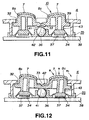
- the third thrusting actuators 8c is thrust in the direction indicated by arrow A or B in Fig.12, the rotary actuating member 10 is rotated in the direction indicated by arrow R1 or towards right in Fig.12.
- the third thrusting actuators 8c thrusts the elastic member 35 downwards.
- the rotary actuating member 10 is rotated in the direction indicated by arrow R1 in Fig. 13, about the fulcrum member 36 as the center of rotation, until the movable contacts 34 are contacted with the stationary contacts 37 to establish the electrical connection.
- the third thrusting actuator 8c is rotated in the direction indicated by arrow R2 in Fig. 13 to separate the movable contacts 34 from the stationary contacts 37. If the third thrusting actuator 8c is rotated further in the direction indicated by arrow R2 in Fig. 13 until the central supporting projection 33 is engaged in the second recess 42, the rotary actuating member 10 is reset to the initial position shown in Fig.11.
- the elastic member 35 is deformed against the force of elasticity.
- the first thrusting actuators 8a is moved in the direction indicated by arrow C in Fig. 10, as the first recess 41 is rotated on the spherical surface of the fulcrum member 36, so that the movable contacts 34 are contacted with the stationary contacts 37 by way of switching.
- the movable contacts 34 and the stationary contacts 37 make up a switch element, which is turned on and off by the contacts 34, 37 being in or out of contact with each other, in order to permit the inputting of a designating signal of moving the display character.
- the operational fulcrum point for the first to fourth thrusting actuators 8a to 8d of the first actuating unit 9 is constituted by relative engagement between the spherically-shaped fulcrum member 36 and the spherically-shaped first recess 41, relative contact between the spherical surfaces can be exploited to change the stroke of the rotary actuating member 10 to perform the switching operation.
- the thrusting actuators 8a to and are discretely provided on the main body unit 4 there is no limitation to the thrusting direction of the first to fourth thrusting actuators 8a to 8d, so that a smooth omnidirectional switching operation can be realized, thus improving operability by prevention of sporadic movements, deviation of the center position or distortion of the rotary actuating member 10.
- the second actuating unit 12 of the actuating device 1 of the present invention is explained in further detail.
- the second actuating unit 12 has a substantially cross-shaped recess 51 towards the opposite side end on the upper surface of the main body unit 4, and apertures 52 in upper and lower and lest and right ends of the recess 51, as shown in Figs. 1 and 2.
- the second actuating unit 12 is constituted by first to fourth thrusting actuators 11a to 11d arranged on the main body unit 4 so that distal ends of the thrusting actuators are protruded towards the upper surface side of the main body unit 4.
- Within the main body unit 4 are arranged switch elements thrust by the first to fourth thrusting actuators 11a to 11d. These switch elements are turned on and off by thrusting actuation of the thrusting actuators 11a to 11d to input command signals of setting the operational functions or executing the operation of the display character.
- first to fourth thrusting actuators 11a to 11d On the end faces of the first to fourth thrusting actuators 11a to 11d are inscribed symbols indicating the functions of the thrusting actuators 11a to 11d, such as ⁇ , X, ⁇ or ⁇ .
- the symbols ⁇ , ⁇ , X and ⁇ are affixed to the first, second, third and fourth thrusting actuators 11a to 11d, respectively.
- the third and fourth thrusting actuators 11c, 11d that are positioned towards the second grip 6 and hence can be acted on easily by the thumb finger when the second grip 6 is held by hand, are set to enter command signals "YES" and "NO" frequently used in prosecuting the game.
- the first to fourth thrusting actuators 11a to 11d may also be designed to indicate the various functions by different colors. That is, the functions of the thrusting actuators 11a to 11d may be indicated by respective different colors.
- the first to fourth thrusting actuators 11a to 11d may be integrally provided on the upper sides thereof contacted by the hand or finger with a top layer formed of the elastomer exhibiting rubber-like elasticity. This top layer is effective to improve contact feeling of hand or finger with the first to fourth thrusting actuators 11a to 11d and hence the operability of the device.
- the third and fourth actuating units 14, 15 are hereinafter explained. These third and fourth actuating units 14, 15 are mounted on substantially cylindrically-shaped mounting portions 47, 48 at corner portions of the connecting sides of the first and second grips 5, 6 to the main body unit 4 for facing each other, as shown in Fig.1.
- the third actuating unit 14 has a multi-directional input device 50, as shown in Fig. 14.
- This multi-directional input device 50 has a box-shaped upper frame 51 and an arched first interlock type member 51, as shown in Fig. 14.
- the first interlock type member 51 is rotatably carried by the upper frame 50 by having a warped end portion 52 engaged with a rotary shaft 54 of a first variable resistor 53a operating as a rotary detector secured to a lateral side 50a of the upper frame 50 and by having a lug 55 of the opposite side warped end portion 52 loosely fitted in an opening 56 formed in a lateral side 50b opposite to the lateral side 50a of the frame 50.
- an actuating shaft 57 having a saucer-like operating portion 58 on its lower end and a disc 59 at a mid portion.
- This disc 59 has an orifice 60.
- the upper portion of the actuating shaft 57 is mounted the rotation actuator 16.
- the second interlock type member 62 for extending at right angles to the actuating shaft 57.
- the second interlock type member 62 has a ball 63 at its center and a pair of arms 64a, 64b extending horizontally with respect to the ball 63.
- the ball 63 has a groove extending from its upper side to its lower side.
- the pin 67 is inserted into the hole 66 and the orifice 67 and the actuating shaft 57 is mounted on the second interlock type member 62 for rotation along the groove 65 with the pin 67 as a supporting shaft.
- the second interlock type member 62 is projected outwards from the lateral side 50d of the upper frame 50 by a rotary shaft 54 of a second variable resistor 53b secured to the lateral side 50c of the upper frame 50 engaging with the end of the arm 64a and by the end of the opposite side arm 64b fitting in an elongated hole 70 formed in the lateral side 50d of the upper frame 50.
- the actuating shaft 57 is passed through the groove 71 of the first interlock type member 51 and subsequently projected outwards via an opening 72 formed in the upper surface of the upper frame 70.
- the actuating shaft 57 is supported on a restoration member 73 which has a saucer-like operating member 58 rotatably housed in its upper surface side recess 74.
- a lower frame 75 is mounted on the lower end of the upper frame 50.
- a supporting wall section 77 for vertically movably housing a flange 76 of the restoration member 73.
- a restoration spring 79 biasing the restoration member 73 upwards.
- the end of the arm 64b of the second interlock type member 62 is caused to compress against the upper edge of the elongated hole 70 in the lateral side 50d of the upper frame 50.
- the second interlock type member 62 is rotatably mounted on the upper frame 50 in a direction perpendicular to the first interlock type member 51 below the first interlock type member 51.
- a thrust type switch element 80 On the lateral side 50d of the upper frame 50 is mounted a thrust type switch element 80 which is changed over by thrusting the spring-biased thrusting actuators 81 against spring bias.
- the thrusting actuators 81 faces the end 82 of the arm 64b of the second interlock type member 62. This end 82 is projected in the same direction as a mounting leg 83 provided on the lower edge of the upper frame 50 and terminals 84 of the first and second variable resistors 53a, 53b
- the operating state of the multi-directional input device 50 is hereinafter explained.
- the actuating shaft 57 is rotated about the point of intersection of the second interlock type member 62 with the pin 67 as the center of rotation. With rotation of the actuating shaft 57, the first interlock type member 51 and the second interlock type member 62 run in rotation.
- the rotary shafts of the first and second variable resistors 53a, 53b are also run n rotation to adjust resistance values.
- the actuating shaft 57 is set upright from the opening 72 in the upper surface of the upper frame 50, with the bottom surface of the operating member 58 compressing against the inner bottom surface of the restoration member 73 by the restoration spring 79.
- the flange 85 having an arcuate portion the radius of curvature of which is progressively increased towards outside of the operating member 58 thrusts the restoration member 73 downwards along the supporting wall section 77 of the lower frame 75 against the elasticity of the restoration spring 79. If the operating pressure on the actuating shaft 57 is relinquished, the neutral state shown in Fig.15 is restored, that is the actuating shaft 57 is restored to its upstanding state, under the boas of the restoration spring 79.
- the actuating shaft 57 in the non-operative state is at a position shown in Fig. 17, in which the end of the arm 64b of the second interlock type member 62 is spaced apart from the thrusting actuators 81 of the switch element 80 and the end of the arm 64b compresses against the upper edge of the elongated opening 70 of the lateral surface 50d of the upper frame 50.
- the end of the arm 64b of the second interlock type member 62 is moved downwards, along the elongated hole 70, against the bias of the restoration spring 79, with the engagement point of the arm 64a with the rotary shaft 54 of the first variable resistor 53a as a fulcrum point, until the end of the arm 64b is retained by the lower edge of the elongated opening 70 operating as a stop.
- the end of the arm 64b thrusts the thrusting actuators 81 of the switch element 80 downwards to change over the state of the switch element 80. If the actuating shaft 57 ceases to be thrust, the end of the arm 64b is restored to the state shown in Fig.
- the third and fourth actuating units 14, 15 can issue the command information of continuously moving the display character, rotating and simultaneously advancing the display character or changing its line of sight.
- the rotation actuators 16 for actuating the third and fourth actuating units 14, 15 are provided with a main actuator body portion 86 mounted on the distal end of the actuating shaft 57, as shown in Figs. 19 and 20.
- the main actuator body portion 86 is molded integrally from a synthetic resin material of higher toughness to inhibit deformation.
- the main actuator body portion 86 has a shank portion 86a on the distal end of which an ellipsoidally-shaped head 86b is protuberantly formed and on the proximal end of which a tubular fitting projection 86c is formed so as to serve for mounting the actuating shaft 57.
- a fitting hole 86d extending from the fitting projection 86c to the mid portion of the shank portion 86a and in which is fitted the actuating shaft 57.
- a semi-spherically-shaped flange 86e On the outer rim of the proximal end of the shank portion 86a is protuberantly formed a semi-spherically-shaped flange 86e.
- a top layer 88 formed of a flexible material, as shown in Figs. 19 and 20.
- the material of the top layer 88 may be an elastomer exhibiting rubber-like elasticity.
- the top layer 88 is formed by two-color molding on the head 86b of the main actuator body portion 86.
- the upper surface side of the top layer 88 is arcuately formed towards above for improving the tactile feeling.
- the rotation actuators 16 having the top layer 88 of a flexible material on its portion touched by hand or finger, it is possible to reduce the impact otherwise applied to the hand orb finger when the actuators are thrust, thus improving the operating feeling on acting on the actuators 16.
- the elastomer of the top layer 88 operates as anti-slip in case of actuation of the rotation actuators 16.
- the top layer 88 is integrally formed with the main actuator body portion 86 by two-color molding, the top layer can be positively affixed to the main actuator body portion 86 to prevent exfoliation on repeated thrusting operations.
- the head 86b may also be formed of an elastomer similar to that of the top layer 88.
- the fifth and sixth actuating units 17, 18, provided on the front side of the main body unit 4, are hereinafter explained.
- the first and second thrusting actuators 19a, 19b and 20a, 20b are arranged so that the distal ends of the fifth and sixth actuating units 17, 18 are protruded from the front side of the main body unit 4 via paired upper and lower parallel openings 91 formed in the front sides of the main body unit 4.
- Within the main body unit 4 are provided switch elements in association with the thrusting actuators 19a, 19b and 20a, 20b.
- the portions of the thrusting actuators 19a, 19b and 20a contacted by the hand or finger may similarly be provided with a top layer formed of elastomer.
- the actuating device 1 of the present invention is provided with vibration-imparting units 92, 92 for imparting vibration to the user to realize more vivid play feeling.
- These vibration-imparting units 92, 92 are provided on the proximal ends of the first and second grips 5, 6 held by the hand or finger of the user gripping the actuating device 1, as shown in Fig.21.
- These vibration-imparting units 92, 92 are made up of a driving motor 93 driven by driving command signals sent from the main body unit of the game machine and an eccentric member 95 mounted on a driving shaft 94 of the driving motor 93.
- the eccentric member 95 is constituted by a metal member of a large weight mass and a semi-circular weight 95a offset relative to the fitting hole 96 engaged by the driving shaft 94 and which is offset relative to the fitting hole 96.
- the driving motor 93 having the eccentric member 95 mounted on the driving shaft 94 is mounted by having a motor housing 98 fitted in a tubular fitting recess 97 of a rectangular cross-section formed on the inner side of the first grip 5, as shown in Fig.23.
- the driving motor 93 is actuated to run the eccentric member 95 in rotation so that the driving motor 93 is vibrated.
- the vibrations of the driving motor 93 are transmitted via a peripheral wall section 97a of the fitting recess 97 to the first grip 5 to transmit the vibrations to the hand or finger holding the grip 5.
- the driving motors 93 of the vibration-imparting units 92, 92 differ in power rating so that, when the vibration-imparting units 92, 92 are driven by a constant driving voltage, the driving motors differ in rotational speeds such that the eccentric members 95 are rotated at differential speeds to produce vibrations of different frequencies.
- the actuating device 1 of the game machine according to the present invention is connected to the main body unit 4 of the game machine as shown in Fig.24.
- the actuating device 1 is connected to the main body unit of the game machine 101 via a connection cord 102 pulled out from a mid portion on the front side of the main body unit 4.
- the connection cord 102 has an end connector 103 which is connected to a jack 104 provided on a lateral surface of the main body unit 101 to connect the actuating device 1 to the main body unit of the game machine 101.
- the main body unit of the game machine 101 has plural jacks 104 to enable connection thereof to plural actuating devices 1.
- the main body unit of the game machine 101 has, enclosed therein, a disc driving unit 105 for reproducing an optical disc having a game program recorded thereon, and a picture processing device for displaying the display character, along with the background picture, on the screen of the television receiver in accordance with the game program recorded on the optical disc.
- the main body unit of the game machine 101 also has a reset switch 106 for resetting the game being executed, a power switch 107 and a lid opening button 109 for opening a lid 108 adapted for opening/closing the disc loading unit of the disc driving unit 105.
- the main body unit of the game machine 101 is connected to a television receiver as a display device for displaying the display character along with the background picture.
- the first to sixth actuating units 9, 12, 14, 15, 17 and 18 can be actuated using up to a maximum of 10 fingers, as the first and second grips 5, 6 are held with both hands.
- the actuating device 1 can also be actuated using only one of the first and second grips 5, 6.
- the display character can perform complex movements to execute a game program with a vivid play feeling. It is possible, for example, to realize a game in which an aircraft or a submarine performs a complex movement through a three-dimensional space for play performance along three axes of movements.
Abstract
Description
- This invention relates to an actuating device used in a game machine employing a display unit of, for example, a television receiver. More particularly, it relates to an actuating device for a game machine having an actuating portion for controlling various operations, such as those of rotating a display character on a display screen, continuously changing the movement speed or deforming the display character.
- Conventionally, a game machine employing a television receiver has a main body unit of the game machine, connected to a television receiver used as a display device, and an actuating device for controlling a display character connected via a connection cable to the main body unit of the game machine and which is displayed on the display screen of the television receiver.
- The main body unit of the game machine has, enclosed therein, a disc driving portion for reproducing an optical disc as a recording medium carrying a game program and a picture processing device for displaying on the screen of the television receiver a display character along with the background picture in accordance with a game program recorded on the optical disc.
- On the actuating device, connected o the main body unit of the game machine, there are arranged plural actuators. The user actuates these actuators to input the command information concerning the operation of the display characters displayed on the display screen of the television receiver to control the movement direction of the display character depending on the command information.
- The actuating device used in this type of the game machine is held by hand or finger during use. On one side and on the opposite side of the main body unit, there are arranged a direction command actuating unit having a cross-shaped or circular direction indicating operating button and a function setting executing unit having plural function setting executing buttons for setting the operating function of the display character or executing its operation. The direction command actuating unit includes four switches having actuators which are arranged orthogonally relative to one another and which are brought into and out of contact with the contact. These switches are selectively turned on and off by the cross-shaped or circular direction command actuators for moving the display character. For example, the display character is digitally moved in the direction along which is arrayed the one of the four switches that is turned on. The function setting executing unit includes switches in association with the plural function setting actuators so that the function of the display character allocated to each button is set or the function proper to the display character is executed.
- The direction command actuator of the actuating device is configured so that the one of the four switches arranged in the mutually perpendicular directions gives a command signal of moving the display character in the direction along which is arrayed the switch turned on, so that it is not possible to give the command information of rotating and simultaneously advancing the display character or changing its line of sight. The result is that it becomes difficult to construct the game program employing the display character performing diversified operations.
- On the other hand, since switches constituting the direction command actuating unit simply is turned on and off by actuation f the direction command actuator to give the command information controlling the movement of the display character, the movement of the display character becomes intermittent such that a series of continuous movements cannot be executed.
- There has been proposed an actuating device having an actuating unit which renders it possible to input a command signal for moving and simultaneously rotating the display character, moving the display character as its speed is varied or changing its configurations.
- This type of the actuating device is described in the Japanese Laying-open Publication H-7-88252.
- There is provided in an actuator adapted to be thrust and simultaneously rotated in the actuating unit adapted for rotating a display character or changing its configuration. This type of the actuator is gripped or thrust by hand or finger.
- The actuator for actuating the direction command actuator is also thrust by being thrust by hand or finger.
- The actuator of the actuating device for the game machine is frequently acted on during execution of the game program. Moreover, the actuating unit is used for prolonged time.
- It is therefore an object of the present invention to provide an actuating unit for the game machine which can give an optimum operating feeling to the actuation of the actuator acted on frequently.
- It is another object of the present invention to provide an actuating unit for the game machine in which the user is not fatigued in hand or finger or even on prolonged use of the unit.
- It is still another object of the present invention to provide an actuating device for a game machine which affords an agreeable use feeling and which is high in reliability.
- It is yet another object of the present invention to provide an actuating device for a game machine which enables the game to be executed with highly vivid play feeling.
- For accomplishing the above objects, an actuating device for a game machine includes first and second grips protruded from one side of each end of the main body unit of the device. On one and the opposite ends of the main body unit are provided first and second actuating units. Each of the first and second actuating units is provided with plural thrusting actuators projected to the upper surface side of the main body unit and with plural signal input elements thrust by these thrusting actuators.
- The actuating device also includes third and fourth actuating units arranged facing each other on the proximal ends of the first and second grips and which are provided with signal input terminals actuated by the thrusting actuators. These third and fourth actuating units can be actuated by thumb fingers of both hands of the user holding the first and second grips.
- The third and fourth actuating units including the signal input terminals actuated by the rotation actuators input to the main body unit of the device command signals enabling rotation and translation simultaneously of the display character displayed on the screen, movement of the display character with varying speed or change of the configuration.
- In the present actuating device for the game machine, each rotation actuator includes a main actuator body portion of a synthetic resin connected to an associated actuating unit and a top portion of a flexible material swollen-out at its distal end and which is formed as-one with the main actuator body portion. Since the top portion contacted with the hand or finger has its distal end swollen-out and is formed of a flexible material, an optimum contact feeling can be realized to improve use feeling.
- There is enclosed in the actuating device of the present invention a vibration-imparting unit which imparts vibrations to the user during operation to execute a game with a vivid play feeling. This vibration-imparting unit is provided in the first and second grips and is made up of a driving motor and an eccentric member mounted on a driving shaft of the motor. The vibration-imparting unit has different vibration-imparting states to realize a more vivid play feeling in executing a game.
- In the actuating device for the game machine according to the present invention, since the top portion of the rotation actuator for entering a command signal in executing the game program, contacted by the hand or finger of the user, is formed of a flexible material and is swollen out at its distal lend, optimum contact feeling may be realized to improve the use feeling.
- Since the main actuator body portion and the top portion making up the rotation actuator is formed by two-color molding, the main actuator body portion and the top portion can be positively unified to each other to assure high operational reliability of the actuating unit.
-
- Fig.1 is a perspective view showing an actuating device for a game machine.
- Fig.2 is a plan view showing the actuating device shown in Fig.1.
- Fig.3 is a back-side view thereof.
- Fig.4 is front view thereof.
- Fig.5 is a right-hand side view thereof.
- Fig.6 is a left-hand side view thereof.
- Fig.7 is a perspective view showing the use state thereof.
- Fig.8 is a side view showing the state of using the actuating device for the game machine mounted n a mounting surface.
- Fig.9 is a perspective view showing essential portions of a first actuating unit.
- Fig.10 is a partial cross-sectional view showing the first actuating unit.
- Fig.11 is a cross-sectional showing the state in which first to fourth thrusting actuators of the first actuating unit.
- Fig. 12 is a cross-sectional view showing the state in which a second actuator of the first actuating unit is being thrust.
- Fig. 13 is a cross-sectional view showing the state in which a second actuator of the first actuating unit has been thrust.
- Fig. 14 is an exploded perspective view showing a multi-directional input device constituting third and fourth actuating units.
- Fig.15 is a cross-sectional view showing the multi-directional input device in an initial state of the actuating shaft.
- Fig.16 is a cross-sectional view showing the multi-directional input device on rotational actuation of the actuating shaft.
- Fig.17 is a perspective view of the multi-directional input device for illustrating the state of actuating a thrusting actuating type switch element, with a portion thereof being broken away.
- Fig.18 is a perspective view of the multi-directional input device for illustrating the actuated state of the thrusting actuating type switch element, with a portion thereof being broken away.
- Fig.19 is a side view showing a rotary actuating member used in the first and second actuating units.
- Fig.20 is a longitudinal cross-sectional view of the rotary actuating member.
- Fig.21 is a bottom view for illustrating the state in which a vibration imparting mechanism is provided in first and second grips.
- Fig.22 is an exploded perspective view showing the vibration imparting mechanism.
- Fig.23 is a perspective view showing the state in which the vibration imparting mechanism has been assembled in a main body unit of the device.
- Fig.24 is a plan view showing the state in which the actuating device for the game machine has been connected to a main body unit of the game machine.
-
- Referring to the drawings, an actuating device for a game machine according to the present invention will be explained in detail.
- The actuating device for the game machine is connected to a main body unit of the game machine having enclosed therein a disc driving unit for reproducing an optical disc as a recording medium carrying a recorded game program and a picture processing device for displaying a display character along with the background on a screen of the television receiver in accordance with a game program recorded on the optical disc.
- An
actuating device 1 for the game machine according to the present invention includes amain body unit 4 made up of anupper half 2 and alower half 3 abutted and connected to each other by fasteners, such as set screws, as shown in Fig.1. From one side of ends of themain body unit 4 are protruded afirst grip 5 and asecond grip 6 which are held by left and right palms when thedevice 1 is connected to the main body unit of the game machine for executing the game There first andsecond grips main body unit 4 as they are flared and spaced apart from each other towards their distal ends, as shown in Figs.2 to 4. For enabling prolonged gripping of the first andsecond grips main body unit 4 towards the distal ends, while being arcuately contoured in peripheral surfaces and at the distal ends, as shown in Figs.2, 5 and 6. - On one end of the
main body unit 4 is provided afirst actuating unit 9, having first to fourth thrustingactuators main body unit 4, as shown in Figs. 1 and 2. The first to fourth thrustingactuators 8a to 8d making up thefirst actuating unit 9 are formed as-one with arotary actuating member 10 having its center portion supported for rotation and are arrayed in mutually perpendicular directions about the center of rotation of therotary actuating member 10. That is, thefirst actuating unit 9 is provided with switch elements as signal inputting elements in association with the first to fourth thrustingactuators 8a to 8d. Thefirst actuating unit 9, operating as a direction command controller for controlling the movement of the display character. By selectively thrusting the first to fourth thrustingactuators 8a to 8d to turn the switches associated with these thrustingactuators 8a to 8d on and off, the display character is moved in the arraying direction of the thrustingly actuated thrustingactuators 8a to 8d. - On the opposite side of the
main body unit 4 is arranged asecond actuating unit 12 having first to fourth thrusting actuators 11a, 11b, 11c, 11d protruded from themain body unit 4 and which are arranged in mutually perpendicular directions, as shown in Figs. 1 and 2. These first to fourth thrusting actuators 11a to 11d are formed as independent members and signal inputting elements, not shown, are provided in association with the thrusting actuators 11a to 11d. Thesecond actuating unit 12 operates as a function setting executing unit for setting the functions of the display character allocated to the thrusting actuators 11a to 11d or executing the functions owned by the display character by turning the switches associated with the first to fourth thrusting actuators 11a to 11d on and off. - The
actuating device 1 according to the present invention includes third andfourth actuators second grips main body unit 4, as shown in Figs. 1 and 2. These third andfourth actuators rotation actuator 16 rotatable through 360° about an actuating shaft as center and a signal inputting element, such as a variable resistance element, actuated by thisrotation actuator 16. Specifically, therotation actuator 16 is mounted at the distal end of an actuating shaft, mounted under the bias of a biasing member for restoration thereof to a neutral position, and is rotated through 360° about the center of rotation of the actuating shaft as the center of rotation. These third andfourth actuators rotation actuator 16, issues a command signal for realizing analog movements, such as rotating and simultaneously moving the display character, moving the display character with a variable speed, or varying its configurations. - On left and right side ends on the front side of the
main body unit 4 opposite to its back side provided with the first andsecond grips sixth actuating units sixth actuating units actuators actuators sixth actuating units actuators actuators - Between the
first actuating unit 9 and thesecond actuating unit 12 on the upper surface of themain body unit 4, there are provided, side-by-side, astart switch 22 for commanding the start of a game and aselection switch 23 for selecting relative facility or difficulty when starting a game, as shown in Figs.1 and 2. On the other hand, there are provided, between thethird actuating unit 14 and thefourth actuating unit 15 on the upper surface of themain body unit 4, amode selection switch 24 for selecting the operating mode of the third andfourth actuating units display unit 25 for displaying the state of the operating modes of the third andfourth actuating units display unit 25 is constituted by a light emitting element, such as LED. By the changeover operation of themode selection switch 24, an operating mode enabling the inputting of a command signal from the third andfourth actuating units fourth actuating units fourth actuating units second actuating unit 12 and the function of the first and second thrustingactuators sixth actuating units display unit 25 is turned on and off depending on the state of these operating modes, while switching is made of the display light. - On the lower side of the
main body unit 4 are formed engagement recesses 26, 27 in which portions of hands or fingers Rf, Lf are engaged when thefirst grip 5 and thesecond grip 6 are gripped by the hands or fingers Rf, Lf, as shown in Figs.5 to 8. These engagement recesses 26, 27 are formed as smoothly curved reentrant recesses, as shown in Figs.5 and 6. - On the front side of the
main body unit 4 are formed depending finger supports 28, 29, in association with the engagement recesses 26, 27, as shown in Figs.5 and 6. Specifically, these finger supports 28, 29 are protuberantly formed from the lower ends ofprotrusions main body unit 4 where the fifth andsixth actuating units - In the actuating device of the present invention, in which the first and
second grips main body unit 4, as described above, these first andsecond grips main body unit 4 by fingers, such that theactuating device 1 an be held in a state in which up to a maximum of ten and at least six fingers can be moved freely. If, for example, the first andsecond grips rotation actuators 16 of the third andfourth actuating units actuators 8a to 8d of thefirst actuating unit 9 and over the first to fourth thrusting actuators 11a to 11d of thesecond actuating unit 12 to permit selective thrusting of therotation actuators 16 and the thrustingactuators 8a to 8d and 11a to 11d. In particular, since therotation actuators 16 of the third andfourth actuating units second grips main body unit 4, therotation actuators 16 are closest to the thumb fingers Rf1, Lf1 of both hands when the first andsecond grips rotation actuators 16 can be easily rotated by both thumb fingers Rf1, Lf1. - Also, when the first and
second grips actuators sixth actuating units - When the
actuating device 1 is gripped by hands or fingers, finger supports 28, 29 can be held as the first andsecond grips main body unit 4 can be held at fixed positions relative to the fingers of the hands of the user. That is, the fingers can be correctly positioned in association with the first tosixth actuating units - The
actuating device 1 according to the present invention can also be set on a planar setting surface S, such as a table, as shown in Fig.8. If theactuating device 1 is set on the setting surface S, with the distal ends of the first andsecond grips actuators 8a to 8d of thefirst actuating unit 9, the first to fourth thrusting actuators 11a to 11d of thesecond actuating unit 12 and therotation actuators 16 of the third andfourth actuating units actuating device 1 of the present invention can be set on the planar setting surface S and the hands placed on the setting surface S, with the first andsecond grips sixth actuating units - The
first actuating unit 9 of theactuating device 1 according to the present invention is explained in further detail. Referring to Figs. 1, 9 and 10, the first to fourth thrustingactuators 8a to 8d are protuberantly formed on therotary actuating member 10 within the substantiallycross-shaped recess 30 on one end side on the upper surface of themain body unit 4. On the upper and lower and left and right ends of thecross-shaped recess 30 are provideddirection indicators apertures 32 are formed in mutually perpendicular directions for allowing the first to fourth thrustingactuators 8a to 8d to be protruded from the upper surface side of themain body unit 4, respectively. The center area surrounded by theseapertures 32 is formed as a central supportingprojection 33 for supporting the center portion on the upper surface side of themain body unit 4, as shown in Fig. 10. This central supportingprojection 33 is formed as-one with the upper inner surface of themain body unit 4. The central supportingprojection 33 is faced by anelastic member 35 having fourmovable contacts 34 thrust by the first to fourth thrustingactuators 8a to 8d. At a center position of theelastic member 35 is held a spherically-shapedfulcrum member 36, such as a steel ball, adapted for supporting the center on the low surface side of therotary actuating member 10. Theelastic member 35 is faced by acircuit substrate 38 including fourstationary contacts 37 adapted for being contacted with and disengaged from themovable contacts 34. - The
rotary actuating member 10 constituting thefirst actuating unit 9 is made up of a circular-shapedbase 39, first to fourth thrustingactuators 8a to 8d formed as-one with the upper part of thebase 39, a spherically-shapedfirst recess 41 in the lower surface of the center portion of thebase 39, adapted for engaging in the spherical surface of a spherically-shapedfulcrum member 36, a spherically-shapedsecond recess 42 in the upper center surface portion of the base 39 adapted for engaging with the central supportingprojection 33 and acontact guide 43 protuberantly formed on the lower side of thebase 39 for thrusting the back surface of themovable contacts 34 of theelastic member 35, as shown in Figs.9 and 10. The four first to fourth thrustingactuators 8a to 8d formed as-one with therotary actuating member 10, are formed on the upper side of the base 39 so that the thrustingactuators 8a to 8d are tapered in a direction towards an imaginary converging point and so that the thrustingactuators 8a to 8d are increased in thickness in a direction from the center towards the outer ends, as shown in Fig.9. The thrustingactuators 8a to 8d are protruded viaapertures 32 from the upper surface of themain body unit 4, as shown in Fig.9. - The
elastic member 35 is sandwiched between acircuit substrate 38 and therotary actuating member 10 and is provided with a number ofmovable contacts 34, such as ruber contacts, corresponding to the number of the first to fourth thrustingactuators 8a to 8d. - A
fulcrum member 36 is spherically-shaped and is arranged at a mid portion of therotary actuating member 10 in register with the central supportingprojection 33. Thefulcrum member 36 is engaged in afirst recess 41 formed at the center of therotary actuating member 10. - If the
rotary actuating member 10 is arranged on themain body unit 4, the first to fourth thrustingactuators 8a to 8d are arranged radially, about the central supportingprojection 33 as center, and are progressively increased in height from the imaginary converging side ends towards the opposite outer ends. The result is that, when the finger is set at the center portion of therecess 30 surrounded by the first to fourth thrustingactuators 8a to 8d, the relative position can be easily discriminated by the tactile feeling at the end of the finger, due to the step difference between the center portion and the first to fourth thrustingactuators 8a to 8d, such that, when the finger end is shifted for switch actuation from the center towards the outer side of therecess 30, which of the first to fourth thrustingactuators 8a to 8d is being thrust can be easily discriminated based solely on the tactile feeling. - The
rotary actuating member 10, formed as-one with the first to fourth thrustingactuators 8a to 8d, are formed by molding a synthetic resin material of a relatively high toughness. The result is that the first to fourth thrustingactuators 8a to 8d of increased toughness are thrust by the hand or finger such that the operational feeling is not optimum. - Thus, a
top layer 7 formed of a soft flexible material is formed as-one with the upper surfaces of the first to fourth thrustingactuators 8a to 8d acted on by the hand or finger, as shown in Figs. 10 and 11. Thetop layer 7 is formed of a material exhibiting rubber-like elasticity. Thetop layer 7 is molded in two colors and formed as-one with the first to fourth thrustingactuators 8a to 8d. Thetop layer 7 is slightly swollen out at the mid portion for improving the tactile feeling. - Since the
top layer 7 of a soft flexible material is provided on the first to fourth thrustingactuators 8a to 8d, it is possible to relieve the impact otherwise applied to the hand or finger on thrusting actuation thus improving the operational feeling on actuation with the hand or finger. Since the elastomer of thetop layer 7 has large friction, it operates for inhibiting the slip of the hand or finger on thrusting actuation of the first to fourth thrustingactuators 8a to 8d. - If, in the above-described
first actuating unit 9, none of the first to fourth thrustingactuators 8a to 8d is actuated, therotary actuating member 10 is uplifted by thecontact guide 43, under the bias of theelastic member 35, as shown in Fig.11, with the central supportingprojection 33 engaging in the spherically-shapedsecond recess 42 of therotary actuating member 10. Simultaneously, the peripheral end of the circular-shapedbase 39 is retained by the end of theaperture 32, therotary actuating member 10 being then retained in an initial position, with the first to fourth thrustingactuators 8a to 8d being projected to outside or on the upper surface side of themain body unit 4. - If, with the first to fourth thrusting
actuators 8a to 8d in the initial position, the third thrustingactuators 8c is thrust in the direction indicated by arrow A or B in Fig.12, therotary actuating member 10 is rotated in the direction indicated by arrow R1 or towards right in Fig.12. Thus, the third thrustingactuators 8c thrusts theelastic member 35 downwards. If the third thrustingactuators 8c is thrust further, therotary actuating member 10 is rotated in the direction indicated by arrow R1 in Fig. 13, about thefulcrum member 36
as the center of rotation, until themovable contacts 34 are contacted with thestationary contacts 37 to establish the electrical connection. - If the thrusting on the third thrusting
actuator 8c is relinquished, thefirst recess 41, kept in spherical surface contact with thefulcrum member 36, is moved away from thefulcrum member 36, under the bias of theelastic member 35. That is, the third thrustingactuator 8c is rotated in the direction indicated by arrow R2 in Fig. 13 to separate themovable contacts 34 from thestationary contacts 37. If the third thrustingactuator 8c is rotated further in the direction indicated by arrow R2 in Fig. 13 until the central supportingprojection 33 is engaged in thesecond recess 42, therotary actuating member 10 is reset to the initial position shown in Fig.11. - On the other hand, if the first thrusting
actuators 8a is thrust in the direction indicated by arrow C in Fig. 10 towards the front side of themain body unit 4, theelastic member 35 is deformed against the force of elasticity. Thus, the first thrustingactuators 8a is moved in the direction indicated by arrow C in Fig. 10, as thefirst recess 41 is rotated on the spherical surface of thefulcrum member 36, so that themovable contacts 34 are contacted with thestationary contacts 37 by way of switching. - The
movable contacts 34 and thestationary contacts 37 make up a switch element, which is turned on and off by thecontacts - Since the operational fulcrum point for the first to fourth thrusting
actuators 8a to 8d of thefirst actuating unit 9 is constituted by relative engagement between the spherically-shapedfulcrum member 36 and the spherically-shapedfirst recess 41, relative contact between the spherical surfaces can be exploited to change the stroke of therotary actuating member 10 to perform the switching operation. In addition, since the thrustingactuators 8a to and are discretely provided on themain body unit 4, there is no limitation to the thrusting direction of the first to fourth thrustingactuators 8a to 8d, so that a smooth omnidirectional switching operation can be realized, thus improving operability by prevention of sporadic movements, deviation of the center position or distortion of therotary actuating member 10. - The
second actuating unit 12 of theactuating device 1 of the present invention is explained in further detail. Thesecond actuating unit 12 has a substantiallycross-shaped recess 51 towards the opposite side end on the upper surface of themain body unit 4, andapertures 52 in upper and lower and lest and right ends of therecess 51, as shown in Figs. 1 and 2. Thesecond actuating unit 12 is constituted by first to fourth thrusting actuators 11a to 11d arranged on themain body unit 4 so that distal ends of the thrusting actuators are protruded towards the upper surface side of themain body unit 4. Within themain body unit 4 are arranged switch elements thrust by the first to fourth thrusting actuators 11a to 11d. These switch elements are turned on and off by thrusting actuation of the thrusting actuators 11a to 11d to input command signals of setting the operational functions or executing the operation of the display character. - On the end faces of the first to fourth thrusting actuators 11a to 11d are inscribed symbols indicating the functions of the thrusting actuators 11a to 11d, such as □, X, ○ or ▵. In the present embodiment, the symbols ▵, □, X and ○ are affixed to the first, second, third and fourth thrusting actuators 11a to 11d, respectively. Specifically, the third and fourth thrusting actuators 11c, 11d, that are positioned towards the
second grip 6 and hence can be acted on easily by the thumb finger when thesecond grip 6 is held by hand, are set to enter command signals "YES" and "NO" frequently used in prosecuting the game. Thus, marks "○" and "X" corresponding to the commands of "YES" and "NO" are inscribed on these third and fourth thrusting actuators 11c and 11d. That is, even if theactuating device 1 is provided with a large number of actuators, the third and fourth thrusting actuators 11c, 11d, used frequently, are located at easy-to operated positions, thus improving operability of the minimum number of the thrusting actuators required in prosecution of the game. - The first to fourth thrusting actuators 11a to 11d may also be designed to indicate the various functions by different colors. That is, the functions of the thrusting actuators 11a to 11d may be indicated by respective different colors.
- Similarly to the first to fourth thrusting
actuators 8a to 8d making up thefirst actuating unit 9, the first to fourth thrusting actuators 11a to 11d may be integrally provided on the upper sides thereof contacted by the hand or finger with a top layer formed of the elastomer exhibiting rubber-like elasticity. This top layer is effective to improve contact feeling of hand or finger with the first to fourth thrusting actuators 11a to 11d and hence the operability of the device. - The third and
fourth actuating units fourth actuating units portions second grips main body unit 4 for facing each other, as shown in Fig.1. - Since the third and
fourth actuating nits third actuating unit 14 is hereinafter explained. - The
third actuating unit 14 has amulti-directional input device 50, as shown in Fig. 14. Thismulti-directional input device 50 has a box-shapedupper frame 51 and an arched firstinterlock type member 51, as shown in Fig. 14. The firstinterlock type member 51 is rotatably carried by theupper frame 50 by having awarped end portion 52 engaged with arotary shaft 54 of a firstvariable resistor 53a operating as a rotary detector secured to alateral side 50a of theupper frame 50 and by having alug 55 of the opposite sidewarped end portion 52 loosely fitted in anopening 56 formed in alateral side 50b opposite to thelateral side 50a of theframe 50. - At a center position of the
upper frame 50 is arranged anactuating shaft 57 having a saucer-like operating portion 58 on its lower end and adisc 59 at a mid portion. Thisdisc 59 has anorifice 60. The upper portion of the actuatingshaft 57 is mounted therotation actuator 16. - Within the
upper frame 50 is arranged a secondinterlock type member 62 for extending at right angles to theactuating shaft 57. The secondinterlock type member 62 has aball 63 at its center and a pair ofarms ball 63. Theball 63 has a groove extending from its upper side to its lower side. After theactuating shaft 57 and thedisc 59 are inserted into thegroove 65, and theorifice 60 is brought into registration with thehole 66 in the lateral side of theball 63, thepin 67 is inserted into thehole 66 and theorifice 67 and the actuatingshaft 57 is mounted on the secondinterlock type member 62 for rotation along thegroove 65 with thepin 67 as a supporting shaft. - The second
interlock type member 62 is projected outwards from thelateral side 50d of theupper frame 50 by arotary shaft 54 of a secondvariable resistor 53b secured to thelateral side 50c of theupper frame 50 engaging with the end of thearm 64a and by the end of theopposite side arm 64b fitting in anelongated hole 70 formed in thelateral side 50d of theupper frame 50. The actuatingshaft 57 is passed through the groove 71 of the firstinterlock type member 51 and subsequently projected outwards via anopening 72 formed in the upper surface of theupper frame 70. - The actuating
shaft 57 is supported on arestoration member 73 which has a saucer-like operating member 58 rotatably housed in its uppersurface side recess 74. - A
lower frame 75 is mounted on the lower end of theupper frame 50. On the upper surface of thelower frame 75 is formed a supportingwall section 77 for vertically movably housing aflange 76 of therestoration member 73. Between the bottom surface of thelower frame 75 and the outerperipheral rim 78 of therestoration member 73 is housed arestoration spring 79 biasing therestoration member 73 upwards. The end of thearm 64b of the secondinterlock type member 62 is caused to compress against the upper edge of theelongated hole 70 in thelateral side 50d of theupper frame 50. The secondinterlock type member 62 is rotatably mounted on theupper frame 50 in a direction perpendicular to the firstinterlock type member 51 below the firstinterlock type member 51. - On the
lateral side 50d of theupper frame 50 is mounted a thrusttype switch element 80 which is changed over by thrusting the spring-biased thrustingactuators 81 against spring bias. The thrustingactuators 81 faces theend 82 of thearm 64b of the secondinterlock type member 62. Thisend 82 is projected in the same direction as a mountingleg 83 provided on the lower edge of theupper frame 50 andterminals 84 of the first and secondvariable resistors - The operating state of the
multi-directional input device 50 is hereinafter explained. - If the user holds the
rotation actuators 16 and rotates the actuatingshaft 57 in an optional direction, the actuatingshaft 57 is rotated about the point of intersection of the secondinterlock type member 62 with thepin 67 as the center of rotation. With rotation of the actuatingshaft 57, the firstinterlock type member 51 and the secondinterlock type member 62 run in rotation. The rotary shafts of the first and secondvariable resistors - The operation for automatic restoration of the actuating
shaft 57 is hereinafter explained. - During the neutral state in which the
actuating shaft 57 is not actuated, the actuatingshaft 57 is set upright from theopening 72 in the upper surface of theupper frame 50, with the bottom surface of the operatingmember 58 compressing against the inner bottom surface of therestoration member 73 by therestoration spring 79. - If the actuating
shaft 57 is tilted clockwise from this state as shown in Fig. 16, theflange 85 having an arcuate portion the radius of curvature of which is progressively increased towards outside of the operatingmember 58 thrusts therestoration member 73 downwards along the supportingwall section 77 of thelower frame 75 against the elasticity of therestoration spring 79. If the operating pressure on theactuating shaft 57 is relinquished, the neutral state shown in Fig.15 is restored, that is the actuatingshaft 57 is restored to its upstanding state, under the boas of therestoration spring 79. - The operation of the
switch element 80 is explained with reference to Figs. 17 and 18. - The actuating
shaft 57 in the non-operative state is at a position shown in Fig. 17, in which the end of thearm 64b of the secondinterlock type member 62 is spaced apart from the thrustingactuators 81 of theswitch element 80 and the end of thearm 64b compresses against the upper edge of theelongated opening 70 of thelateral surface 50d of theupper frame 50. If the actuatingshaft 57 is thrust downwards from this state, the end of thearm 64b of the secondinterlock type member 62 is moved downwards, along theelongated hole 70, against the bias of therestoration spring 79, with the engagement point of thearm 64a with therotary shaft 54 of the firstvariable resistor 53a as a fulcrum point, until the end of thearm 64b is retained by the lower edge of theelongated opening 70 operating as a stop. At this time, the end of thearm 64b thrusts the thrustingactuators 81 of theswitch element 80 downwards to change over the state of theswitch element 80. If the actuatingshaft 57 ceases to be thrust, the end of thearm 64b is restored to the state shown in Fig. 17, against the recoiling force of therestoration spring 79, with the end of thearm 64b being reset to the state of Fig. 17 in which the end of the arm compresses against the upper edge of thegroove 30. Theswitch element 80 is in operation even if the thrustingactuators 81 are thrust when the actuatingshaft 57 has been rotated in an optional direction. - By rotation of the
rotation actuators 16 and consequent actuation of the first and secondvariable resistors fourth actuating units - It is noted that the
rotation actuators 16 for actuating the third andfourth actuating units actuator body portion 86 mounted on the distal end of the actuatingshaft 57, as shown in Figs. 19 and 20. The mainactuator body portion 86 is molded integrally from a synthetic resin material of higher toughness to inhibit deformation. The mainactuator body portion 86 has ashank portion 86a on the distal end of which an ellipsoidally-shapedhead 86b is protuberantly formed and on the proximal end of which a tubularfitting projection 86c is formed so as to serve for mounting the actuatingshaft 57. There is bored afitting hole 86d extending from thefitting projection 86c to the mid portion of theshank portion 86a and in which is fitted the actuatingshaft 57. On the outer rim of the proximal end of theshank portion 86a is protuberantly formed a semi-spherically-shapedflange 86e. When therotation actuators 16 are fitted on theactuating shaft 57, theflange 86e fits in anopening 87 formed in themain body unit 4 to permit rotation of therotation actuators 16 in order to cover theopening 87 and in order to guide the rotation of therotation actuators 16, as shown in Figs. 1 and 2. - On the upper surface side of the
head 86b, contacted by the hand or finger, there is integrally formed atop layer 88 formed of a flexible material, as shown in Figs. 19 and 20. The material of thetop layer 88 may be an elastomer exhibiting rubber-like elasticity. Thetop layer 88 is formed by two-color molding on thehead 86b of the mainactuator body portion 86. The upper surface side of thetop layer 88 is arcuately formed towards above for improving the tactile feeling. - With the
rotation actuators 16, having thetop layer 88 of a flexible material on its portion touched by hand or finger, it is possible to reduce the impact otherwise applied to the hand orb finger when the actuators are thrust, thus improving the operating feeling on acting on theactuators 16. The elastomer of thetop layer 88 operates as anti-slip in case of actuation of therotation actuators 16. - Since the
top layer 88 is integrally formed with the mainactuator body portion 86 by two-color molding, the top layer can be positively affixed to the mainactuator body portion 86 to prevent exfoliation on repeated thrusting operations. - Although the
top layer 88 of a flexible material is formed for covering the outer periphery of thehead 86b from the upper side, as shown in Fig.20, thehead 86b may also be formed of an elastomer similar to that of thetop layer 88. - The fifth and
sixth actuating units main body unit 4, are hereinafter explained. - As for the fifth and
sixth actuating units actuators sixth actuating units main body unit 4 via paired upper and lowerparallel openings 91 formed in the front sides of themain body unit 4. Within themain body unit 4 are provided switch elements in association with the thrustingactuators actuators - The
actuating device 1 of the present invention is provided with vibration-impartingunits units second grips actuating device 1, as shown in Fig.21. These vibration-impartingunits motor 93 driven by driving command signals sent from the main body unit of the game machine and aneccentric member 95 mounted on a drivingshaft 94 of the drivingmotor 93. Theeccentric member 95 is constituted by a metal member of a large weight mass and asemi-circular weight 95a offset relative to thefitting hole 96 engaged by the drivingshaft 94 and which is offset relative to thefitting hole 96. The drivingmotor 93 having theeccentric member 95 mounted on the drivingshaft 94 is mounted by having amotor housing 98 fitted in a tubularfitting recess 97 of a rectangular cross-section formed on the inner side of thefirst grip 5, as shown in Fig.23. - In the above-described vibration-imparting
units motor 93 is actuated to run theeccentric member 95 in rotation so that the drivingmotor 93 is vibrated. The vibrations of the drivingmotor 93 are transmitted via aperipheral wall section 97a of thefitting recess 97 to thefirst grip 5 to transmit the vibrations to the hand or finger holding thegrip 5. - It is noted that the driving
motors 93 of the vibration-impartingunits units eccentric members 95 are rotated at differential speeds to produce vibrations of different frequencies. - The
actuating device 1 of the game machine according to the present invention is connected to themain body unit 4 of the game machine as shown in Fig.24. - The
actuating device 1 is connected to the main body unit of thegame machine 101 via aconnection cord 102 pulled out from a mid portion on the front side of themain body unit 4. Theconnection cord 102 has anend connector 103 which is connected to ajack 104 provided on a lateral surface of themain body unit 101 to connect theactuating device 1 to the main body unit of thegame machine 101. - It is noted that the main body unit of the
game machine 101 hasplural jacks 104 to enable connection thereof toplural actuating devices 1. - The main body unit of the
game machine 101 has, enclosed therein, adisc driving unit 105 for reproducing an optical disc having a game program recorded thereon, and a picture processing device for displaying the display character, along with the background picture, on the screen of the television receiver in accordance with the game program recorded on the optical disc. The main body unit of thegame machine 101 also has areset switch 106 for resetting the game being executed, apower switch 107 and alid opening button 109 for opening alid 108 adapted for opening/closing the disc loading unit of thedisc driving unit 105. - The main body unit of the
game machine 101 is connected to a television receiver as a display device for displaying the display character along with the background picture. - In the above-described
actuating device 1 for the game machine according to the present invention, the first tosixth actuating units second grips actuating device 1 can also be actuated using only one of the first andsecond grips - That is, by suitably actuating the first to
sixth actuating units - Therefore, using the
actuating device 1 for the game machine according to the present invention the display character can perform complex movements to execute a game program with a vivid play feeling. It is possible, for example, to realize a game in which an aircraft or a submarine performs a complex movement through a three-dimensional space for play performance along three axes of movements.
Claims (5)
- An actuating device for a game machine comprising:first and second grips protruded from one side of each end of a main body unit of the device;a first actuating unit provided on one end of the main body unit and having a plurality of thrusting actuators protruding to an upper surface side of the main body unit and a plurality of signal input elements thrust by said thrusting actuators;a second actuating unit provided on the other end of the main body unit and having a plurality of thrusting actuators protruding to an upper surface side of the main body unit and a plurality of signal input elements thrust by said thrusting actuators; andthird and fourth actuating units arranged facing each other on the proximal ends of said first and second grips and adapted for being actuated by said thrusting actuators;
said thrusting actuators each having a main actuator body portion of synthetic resin connected to the associated actuating unit and a top portion of a flexible material having a swollen-out end face portion, said top portion being integrally formed with said main actuator body portion. - The actuating device for a game machine according to claim 1 wherein the main actuator body portion and the top portion are formed by two-color molding.
- The actuating device for a game machine according to claim 1 wherein the upper surfaces of the thrusting actuators are integrally formed with top portions of a flexible material.
- The actuating device for a game machine according to claim 1 wherein vibration-imparting units each including a driving motor and an eccentric member mounted on a driving shaft of the driving motor.
- The actuating device for a game machine according to claim 1 wherein the vibration-imparting units provided in the first and second grips are of different vibration-imparting configurations.
Applications Claiming Priority (3)
| Application Number | Priority Date | Filing Date | Title |
|---|---|---|---|
| JP257216/97 | 1997-09-22 | ||
| JP9257216A JPH1190042A (en) | 1997-09-22 | 1997-09-22 | Controller for game machine |
| JP25721697 | 1997-09-22 |
Publications (3)
| Publication Number | Publication Date |
|---|---|
| EP0903659A2 true EP0903659A2 (en) | 1999-03-24 |
| EP0903659A3 EP0903659A3 (en) | 2003-10-29 |
| EP0903659B1 EP0903659B1 (en) | 2006-11-29 |
Family
ID=17303286
Family Applications (1)
| Application Number | Title | Priority Date | Filing Date |
|---|---|---|---|
| EP98117834A Expired - Lifetime EP0903659B1 (en) | 1997-09-22 | 1998-09-21 | Actuating device for game machine |
Country Status (13)
| Country | Link |
|---|---|
| US (1) | US6394906B1 (en) |
| EP (1) | EP0903659B1 (en) |
| JP (1) | JPH1190042A (en) |
| KR (1) | KR100627768B1 (en) |
| CN (1) | CN1139417C (en) |
| AU (1) | AU752420B2 (en) |
| CA (1) | CA2247718C (en) |
| DE (1) | DE69836525T2 (en) |
| ES (1) | ES2273389T3 (en) |
| HK (1) | HK1017746A1 (en) |
| MY (1) | MY125892A (en) |
| SG (1) | SG68688A1 (en) |
| TW (1) | TW369431B (en) |
Cited By (6)
| Publication number | Priority date | Publication date | Assignee | Title |
|---|---|---|---|---|
| EP1156640A2 (en) * | 2000-05-17 | 2001-11-21 | Nec Corporation | Portable folding communication unit |
| US6641480B2 (en) | 2001-01-29 | 2003-11-04 | Microsoft Corporation | Force feedback mechanism for gamepad device |
| EP1560238A1 (en) * | 2004-01-27 | 2005-08-03 | Hsien-Ta Huang | Buffering protective handheld controller |
| DE102015102317A1 (en) * | 2015-02-18 | 2016-08-18 | Elobau Gmbh & Co. Kg | joystick |
| EP2908224A4 (en) * | 2012-10-15 | 2016-11-02 | Sony Interactive Entertainment Inc | Control device |
| US9690392B2 (en) | 2012-10-15 | 2017-06-27 | Sony Corporation | Operating device including a touch sensor |
Families Citing this family (57)
| Publication number | Priority date | Publication date | Assignee | Title |
|---|---|---|---|---|
| US6222525B1 (en) | 1992-03-05 | 2001-04-24 | Brad A. Armstrong | Image controllers with sheet connected sensors |
| US8674932B2 (en) | 1996-07-05 | 2014-03-18 | Anascape, Ltd. | Image controller |
| WO1998016285A1 (en) | 1996-10-11 | 1998-04-23 | Sony Computer Entertainment Inc. | Operating device for game machines |
| JP2000084250A (en) * | 1998-09-16 | 2000-03-28 | Taito Corp | Impact feeling generator for game machine |
| JP2001137544A (en) * | 1999-08-27 | 2001-05-22 | Sony Computer Entertainment Inc | Entertainment system, entertainment device, recording medium and program |
| DE20080209U1 (en) | 1999-09-28 | 2001-08-09 | Immersion Corp | Control of haptic sensations for interface devices with vibrotactile feedback |
| JP2001113048A (en) * | 1999-10-14 | 2001-04-24 | Sony Corp | Operating device for game machine |
| JP2001143556A (en) * | 1999-11-12 | 2001-05-25 | Sony Computer Entertainment Inc | Operating device |
| JP3260348B2 (en) * | 2000-02-17 | 2002-02-25 | 株式会社アスキー | Attachments and game consoles for controllers |
| JP2002095863A (en) * | 2000-07-03 | 2002-04-02 | Sony Computer Entertainment Inc | Program exciting system, program exciting apparatus, recording medium and program, and method for switching viewpoint and method for switching sight |
| EP1330811B1 (en) * | 2000-09-28 | 2012-08-22 | Immersion Corporation | Directional tactile feedback for haptic feedback interface devices |
| US7084854B1 (en) | 2000-09-28 | 2006-08-01 | Immersion Corporation | Actuator for providing tactile sensations and device for directional tactile sensations |
| JP3608726B2 (en) * | 2001-04-19 | 2005-01-12 | 株式会社ソニー・コンピュータエンタテインメント | controller |
| US6524188B2 (en) * | 2001-06-26 | 2003-02-25 | Yung-Chung Wang | Game controller with a monitor |
| US6888537B2 (en) * | 2002-02-13 | 2005-05-03 | Siemens Technology-To-Business Center, Llc | Configurable industrial input devices that use electrically conductive elastomer |
| JP3457305B1 (en) * | 2002-09-19 | 2003-10-14 | 株式会社コナミコンピュータエンタテインメント東京 | GAME DEVICE, GAME CONTROL METHOD, AND PROGRAM |
| CN1713941A (en) * | 2003-01-17 | 2005-12-28 | 尼科株式会社 | Transmitter for wireless control |
| US20050174337A1 (en) * | 2004-02-11 | 2005-08-11 | Nielsen Paul S. | Electronic handheld drawing and gaming system using television monitor |
| US7167159B2 (en) * | 2004-07-01 | 2007-01-23 | Geltabz, Inc. | Joystick cover |
| US7535464B1 (en) * | 2004-08-30 | 2009-05-19 | Microsoft Corporation | Navigation wheel having discrete switches |
| US7859514B1 (en) | 2005-07-19 | 2010-12-28 | Young Park | Multi-functional user interface for electronic devices |
| CN101278244B (en) * | 2005-10-06 | 2012-05-30 | Abb股份有限公司 | Control system and teaching kit for industry robot |
| US8108092B2 (en) | 2006-07-14 | 2012-01-31 | Irobot Corporation | Autonomous behaviors for a remote vehicle |
| US7843431B2 (en) * | 2007-04-24 | 2010-11-30 | Irobot Corporation | Control system for a remote vehicle |
| US20090225028A1 (en) * | 2008-02-26 | 2009-09-10 | Clem Abrams | Point and click device for computer |
| US8014148B2 (en) * | 2008-02-28 | 2011-09-06 | Panasonic Corporation | Electronic device |
| JP2012120716A (en) * | 2010-12-09 | 2012-06-28 | Pilot Ink Co Ltd | Picture matching toy, and picture matching toy set |
| US8803803B2 (en) * | 2011-01-25 | 2014-08-12 | Sony Corporation | Operation member provided in electronic device, and electronic device |
| CN102671375B (en) * | 2011-03-09 | 2015-06-03 | 台达电子工业股份有限公司 | Key controller |
| US8641525B2 (en) | 2011-06-17 | 2014-02-04 | Ironburg Inventions Ltd. | Controller for video game console |
| CN102274635A (en) * | 2011-07-30 | 2011-12-14 | 周海涛 | Game controller |
| JP5941276B2 (en) * | 2011-12-09 | 2016-06-29 | アルプス電気株式会社 | Multi-directional input device |
| CN104205278B (en) | 2012-03-13 | 2017-03-08 | 索尼电脑娱乐公司 | Operation equipment |
| WO2013136960A1 (en) * | 2012-03-13 | 2013-09-19 | 株式会社ソニー・コンピュータエンタテインメント | Operating device |
| JP6063201B2 (en) | 2012-10-15 | 2017-01-18 | 株式会社ソニー・インタラクティブエンタテインメント | Operation device |
| US10328344B2 (en) | 2013-10-11 | 2019-06-25 | Valve Corporation | Game controller systems and methods |
| KR101397457B1 (en) * | 2014-02-28 | 2014-05-21 | 강신권 | Game controller apparatus |
| JP6209575B2 (en) * | 2015-04-24 | 2017-10-04 | 任天堂株式会社 | Multi-directional input device |
| US9921652B2 (en) * | 2015-06-29 | 2018-03-20 | Apple Inc. | Input with haptic feedback |
| US9971407B2 (en) | 2015-09-30 | 2018-05-15 | Apple Inc. | Haptic feedback for rotary inputs |
| WO2017152139A1 (en) | 2016-03-04 | 2017-09-08 | Apple Inc. | Input with haptic feedback |
| JP7083226B2 (en) | 2016-06-10 | 2022-06-10 | 任天堂株式会社 | Game controller |
| JP6677580B2 (en) | 2016-06-10 | 2020-04-08 | 任天堂株式会社 | Game controller |
| JP6782567B2 (en) | 2016-06-10 | 2020-11-11 | 任天堂株式会社 | Game controller |
| JP6576432B2 (en) * | 2016-06-10 | 2019-09-18 | 任天堂株式会社 | Game controller |
| EP3254739B1 (en) | 2016-06-10 | 2020-03-25 | Nintendo Co., Ltd. | Game controller |
| JP6893763B2 (en) | 2016-06-10 | 2021-06-23 | 任天堂株式会社 | Game controller |
| US10406431B2 (en) | 2016-08-11 | 2019-09-10 | Valve Corporation | Hand-held controller with a back shell and underlying force sensitive resistors |
| US10722786B2 (en) | 2016-08-11 | 2020-07-28 | Valve Corporation | Video game controller with unitary back shell for button control and battery access |
| US11794094B2 (en) | 2016-10-17 | 2023-10-24 | Aquimo Inc. | Method and system for using sensors of a control device for control of a game |
| AU2017426877B2 (en) | 2017-08-11 | 2023-04-06 | Razer (Asia-Pacific) Pte. Ltd. | Height extension of analog stick |
| CN108766122B (en) * | 2018-06-22 | 2020-06-05 | 常州轻工职业技术学院 | Device for improving English pronunciation quality by touch sense |
| CA201150S (en) | 2021-02-08 | 2022-10-19 | Collective Minds Gaming Co Ltd | Adapter for a video game controller |
| USD983200S1 (en) | 2021-02-08 | 2023-04-11 | Collective Minds Gaming Co. Ltd. | Stop for a trigger button of a video game controller |
| CN117716328A (en) | 2021-09-21 | 2024-03-15 | 索尼互动娱乐股份有限公司 | Input device with variable handle |
| WO2023171225A1 (en) * | 2022-03-08 | 2023-09-14 | アルプスアルパイン株式会社 | Multidirectional input device |
| USD978970S1 (en) * | 2022-10-31 | 2023-02-21 | Lisong Qiu | Game controller |
Citations (1)
| Publication number | Priority date | Publication date | Assignee | Title |
|---|---|---|---|---|
| JPH0788252A (en) | 1993-09-22 | 1995-04-04 | Sony Corp | Manipulation device for game machine |
Family Cites Families (14)
| Publication number | Priority date | Publication date | Assignee | Title |
|---|---|---|---|---|
| US4486629A (en) * | 1983-07-18 | 1984-12-04 | Coleco Industries, Inc. | Joystick controller |
| JPS6244339U (en) * | 1985-08-31 | 1987-03-17 | ||
| JPS62194389A (en) | 1986-02-21 | 1987-08-26 | ミクストン株式会社 | Rotary rising and falling door |
| JP2615607B2 (en) * | 1987-04-07 | 1997-06-04 | ソニー株式会社 | Input operation device |
| US5701142A (en) * | 1990-07-24 | 1997-12-23 | In-Control Solutions, Inc. | Pointing stick with tripod actuator for cursor control in a computer keyboard |
| US5468924A (en) * | 1993-07-01 | 1995-11-21 | Sumitomo Wiring Systems, Ltd. | Joy stick support structure for multi-directional switch |
| US5555004A (en) * | 1993-08-30 | 1996-09-10 | Hosiden Corporation | Input control device |
| JP2533285B2 (en) | 1993-10-14 | 1996-09-11 | コナミ株式会社 | Raygun for TV game machine |
| US5473126A (en) * | 1994-01-31 | 1995-12-05 | Wu; Donald | Joystick switch assembly |
| US6004134A (en) * | 1994-05-19 | 1999-12-21 | Exos, Inc. | Interactive simulation including force feedback |
| JP4036246B2 (en) * | 1994-08-02 | 2008-01-23 | 任天堂株式会社 | Game console operating device |
| US5670955A (en) * | 1995-01-31 | 1997-09-23 | Microsoft Corporation | Method and apparatus for generating directional and force vector in an input device |
| MX9704155A (en) * | 1995-10-09 | 1997-09-30 | Nintendo Co Ltd | Three-dimensional image processing system. |
| US5801918A (en) * | 1996-07-12 | 1998-09-01 | Hand Held Products, Inc. | Ergonomic housing for a micro computer |
-
1997
- 1997-09-22 JP JP9257216A patent/JPH1190042A/en active Pending
-
1998
- 1998-09-15 AU AU84242/98A patent/AU752420B2/en not_active Expired
- 1998-09-15 TW TW087115357A patent/TW369431B/en not_active IP Right Cessation
- 1998-09-17 SG SG1998003709A patent/SG68688A1/en unknown
- 1998-09-21 ES ES98117834T patent/ES2273389T3/en not_active Expired - Lifetime
- 1998-09-21 DE DE69836525T patent/DE69836525T2/en not_active Expired - Lifetime
- 1998-09-21 KR KR1019980039000A patent/KR100627768B1/en not_active IP Right Cessation
- 1998-09-21 CA CA002247718A patent/CA2247718C/en not_active Expired - Lifetime
- 1998-09-21 MY MYPI98004340A patent/MY125892A/en unknown
- 1998-09-21 EP EP98117834A patent/EP0903659B1/en not_active Expired - Lifetime
- 1998-09-22 US US09/158,062 patent/US6394906B1/en not_active Expired - Lifetime
- 1998-09-22 CN CNB981195415A patent/CN1139417C/en not_active Expired - Lifetime
-
1999
- 1999-07-02 HK HK99102800A patent/HK1017746A1/en not_active IP Right Cessation
Patent Citations (1)
| Publication number | Priority date | Publication date | Assignee | Title |
|---|---|---|---|---|
| JPH0788252A (en) | 1993-09-22 | 1995-04-04 | Sony Corp | Manipulation device for game machine |
Cited By (14)
| Publication number | Priority date | Publication date | Assignee | Title |
|---|---|---|---|---|
| US7460887B2 (en) | 2000-05-17 | 2008-12-02 | Nec Corporation | Portable folding communication unit |
| EP1156640A3 (en) * | 2000-05-17 | 2003-09-24 | Nec Corporation | Portable folding communication unit |
| EP1156640A2 (en) * | 2000-05-17 | 2001-11-21 | Nec Corporation | Portable folding communication unit |
| US7503852B2 (en) | 2001-01-29 | 2009-03-17 | Microsoft Corporation | Force feedback mechanism for gamepad device |
| US6824468B2 (en) | 2001-01-29 | 2004-11-30 | Microsoft Corporation | Force feedback mechanism for gamepad device |
| US6641480B2 (en) | 2001-01-29 | 2003-11-04 | Microsoft Corporation | Force feedback mechanism for gamepad device |
| US7507158B2 (en) | 2001-01-29 | 2009-03-24 | Microsoft Corporation | Force feedback mechanism for gamepad device |
| EP1560238A1 (en) * | 2004-01-27 | 2005-08-03 | Hsien-Ta Huang | Buffering protective handheld controller |
| EP2908224A4 (en) * | 2012-10-15 | 2016-11-02 | Sony Interactive Entertainment Inc | Control device |
| US9690392B2 (en) | 2012-10-15 | 2017-06-27 | Sony Corporation | Operating device including a touch sensor |
| US9789395B2 (en) | 2012-10-15 | 2017-10-17 | Sony Interactive Entertainment Inc. | Operating device |
| US10507386B2 (en) | 2012-10-15 | 2019-12-17 | Sony Interactive Entertainment Inc. | Operating device |
| US10603576B2 (en) | 2012-10-15 | 2020-03-31 | Sony Interactive Entertainment Inc. | Operating device including a touch sensor |
| DE102015102317A1 (en) * | 2015-02-18 | 2016-08-18 | Elobau Gmbh & Co. Kg | joystick |
Also Published As
| Publication number | Publication date |
|---|---|
| CA2247718C (en) | 2008-01-29 |
| DE69836525D1 (en) | 2007-01-11 |
| EP0903659A3 (en) | 2003-10-29 |
| ES2273389T3 (en) | 2007-05-01 |
| KR100627768B1 (en) | 2007-07-09 |
| US6394906B1 (en) | 2002-05-28 |
| AU8424298A (en) | 1999-04-15 |
| EP0903659B1 (en) | 2006-11-29 |
| JPH1190042A (en) | 1999-04-06 |
| DE69836525T2 (en) | 2007-12-13 |
| KR19990029997A (en) | 1999-04-26 |
| CN1220905A (en) | 1999-06-30 |
| MY125892A (en) | 2006-08-30 |
| SG68688A1 (en) | 1999-11-16 |
| HK1017746A1 (en) | 1999-11-26 |
| AU752420B2 (en) | 2002-09-19 |
| CN1139417C (en) | 2004-02-25 |
| TW369431B (en) | 1999-09-11 |
| CA2247718A1 (en) | 1999-03-22 |
Similar Documents
| Publication | Publication Date | Title |
|---|---|---|
| EP0903659B1 (en) | Actuating device for game machine | |
| US9180367B2 (en) | Operating device for game machine | |
| US6171191B1 (en) | Actuating device and system exploiting the actuating device | |
| JP3628358B2 (en) | Game console controller | |
| US20040048665A1 (en) | Control unit and system utilizing the control unit | |
| JPH08180770A (en) | Operation apparatus for game machine | |
| JP2001143556A (en) | Operating device | |
| US11173390B2 (en) | Game controller | |
| EP0205726B1 (en) | Image controlling method and device for carrying out the same | |
| JPH06139878A (en) | Controller for television game machine | |
| MXPA98007711A (en) | Drive device for thread machine | |
| AU9707001A (en) | Operating device for game machine | |
| JP3380233B2 (en) | Game console controller | |
| JP3453263B2 (en) | Operation device for game machine | |
| JPH0975544A (en) | Controller for game machine |
Legal Events
| Date | Code | Title | Description |
|---|---|---|---|
| PUAI | Public reference made under article 153(3) epc to a published international application that has entered the european phase |
Free format text: ORIGINAL CODE: 0009012 |
|
| AK | Designated contracting states |
Kind code of ref document: A2 Designated state(s): AT BE CH CY DE DK ES FI FR GB GR IE IT LI LU MC NL PT SE |
|
| AX | Request for extension of the european patent |
Free format text: AL;LT;LV;MK;RO;SI |
|
| PUAL | Search report despatched |
Free format text: ORIGINAL CODE: 0009013 |
|
| AK | Designated contracting states |
Kind code of ref document: A3 Designated state(s): AT BE CH CY DE DK ES FI FR GB GR IE IT LI LU MC NL PT SE |
|
| AX | Request for extension of the european patent |
Extension state: AL LT LV MK RO SI |
|
| 17P | Request for examination filed |
Effective date: 20040329 |
|
| 17Q | First examination report despatched |
Effective date: 20040518 |
|
| AKX | Designation fees paid |
Designated state(s): DE ES FR GB IT NL |
|
| GRAP | Despatch of communication of intention to grant a patent |
Free format text: ORIGINAL CODE: EPIDOSNIGR1 |
|
| GRAS | Grant fee paid |
Free format text: ORIGINAL CODE: EPIDOSNIGR3 |
|
| GRAA | (expected) grant |
Free format text: ORIGINAL CODE: 0009210 |
|
| AK | Designated contracting states |
Kind code of ref document: B1 Designated state(s): DE ES FR GB IT NL |
|
| REG | Reference to a national code |
Ref country code: GB Ref legal event code: FG4D |
|
| REF | Corresponds to: |
Ref document number: 69836525 Country of ref document: DE Date of ref document: 20070111 Kind code of ref document: P |
|
| REG | Reference to a national code |
Ref country code: HK Ref legal event code: GR Ref document number: 1017746 Country of ref document: HK |
|
| REG | Reference to a national code |
Ref country code: ES Ref legal event code: FG2A Ref document number: 2273389 Country of ref document: ES Kind code of ref document: T3 |
|
| ET | Fr: translation filed | ||
| PLBE | No opposition filed within time limit |
Free format text: ORIGINAL CODE: 0009261 |
|
| STAA | Information on the status of an ep patent application or granted ep patent |
Free format text: STATUS: NO OPPOSITION FILED WITHIN TIME LIMIT |
|
| 26N | No opposition filed |
Effective date: 20070830 |
|
| REG | Reference to a national code |
Ref country code: FR Ref legal event code: PLFP Year of fee payment: 19 |
|
| REG | Reference to a national code |
Ref country code: FR Ref legal event code: PLFP Year of fee payment: 20 |
|
| PGFP | Annual fee paid to national office [announced via postgrant information from national office to epo] |
Ref country code: NL Payment date: 20170814 Year of fee payment: 20 |
|
| PGFP | Annual fee paid to national office [announced via postgrant information from national office to epo] |
Ref country code: IT Payment date: 20170925 Year of fee payment: 20 Ref country code: FR Payment date: 20170810 Year of fee payment: 20 Ref country code: GB Payment date: 20170920 Year of fee payment: 20 Ref country code: DE Payment date: 20170912 Year of fee payment: 20 |
|
| PGFP | Annual fee paid to national office [announced via postgrant information from national office to epo] |
Ref country code: ES Payment date: 20171005 Year of fee payment: 20 |
|
| REG | Reference to a national code |
Ref country code: DE Ref legal event code: R071 Ref document number: 69836525 Country of ref document: DE |
|
| REG | Reference to a national code |
Ref country code: NL Ref legal event code: MK Effective date: 20180920 |
|
| REG | Reference to a national code |
Ref country code: GB Ref legal event code: PE20 Expiry date: 20180920 |
|
| PG25 | Lapsed in a contracting state [announced via postgrant information from national office to epo] |
Ref country code: GB Free format text: LAPSE BECAUSE OF EXPIRATION OF PROTECTION Effective date: 20180920 |
|
| REG | Reference to a national code |
Ref country code: ES Ref legal event code: FD2A Effective date: 20220127 |
|
| PG25 | Lapsed in a contracting state [announced via postgrant information from national office to epo] |
Ref country code: ES Free format text: LAPSE BECAUSE OF EXPIRATION OF PROTECTION Effective date: 20180922 |