EP0903901B1 - Network service server load balancing - Google Patents
Network service server load balancing Download PDFInfo
- Publication number
- EP0903901B1 EP0903901B1 EP19980302410 EP98302410A EP0903901B1 EP 0903901 B1 EP0903901 B1 EP 0903901B1 EP 19980302410 EP19980302410 EP 19980302410 EP 98302410 A EP98302410 A EP 98302410A EP 0903901 B1 EP0903901 B1 EP 0903901B1
- Authority
- EP
- European Patent Office
- Prior art keywords
- control units
- control unit
- server
- load balancing
- packets
- Prior art date
- Legal status (The legal status is an assumption and is not a legal conclusion. Google has not performed a legal analysis and makes no representation as to the accuracy of the status listed.)
- Expired - Lifetime
Links
Images


Classifications
-
- H—ELECTRICITY
- H04—ELECTRIC COMMUNICATION TECHNIQUE
- H04L—TRANSMISSION OF DIGITAL INFORMATION, e.g. TELEGRAPHIC COMMUNICATION
- H04L47/00—Traffic control in data switching networks
- H04L47/10—Flow control; Congestion control
- H04L47/11—Identifying congestion
-
- H—ELECTRICITY
- H04—ELECTRIC COMMUNICATION TECHNIQUE
- H04L—TRANSMISSION OF DIGITAL INFORMATION, e.g. TELEGRAPHIC COMMUNICATION
- H04L47/00—Traffic control in data switching networks
- H04L47/10—Flow control; Congestion control
-
- H—ELECTRICITY
- H04—ELECTRIC COMMUNICATION TECHNIQUE
- H04L—TRANSMISSION OF DIGITAL INFORMATION, e.g. TELEGRAPHIC COMMUNICATION
- H04L47/00—Traffic control in data switching networks
- H04L47/10—Flow control; Congestion control
- H04L47/12—Avoiding congestion; Recovering from congestion
- H04L47/125—Avoiding congestion; Recovering from congestion by balancing the load, e.g. traffic engineering
-
- H—ELECTRICITY
- H04—ELECTRIC COMMUNICATION TECHNIQUE
- H04L—TRANSMISSION OF DIGITAL INFORMATION, e.g. TELEGRAPHIC COMMUNICATION
- H04L67/00—Network arrangements or protocols for supporting network services or applications
- H04L67/01—Protocols
- H04L67/10—Protocols in which an application is distributed across nodes in the network
- H04L67/1001—Protocols in which an application is distributed across nodes in the network for accessing one among a plurality of replicated servers
- H04L67/1004—Server selection for load balancing
- H04L67/1023—Server selection for load balancing based on a hash applied to IP addresses or costs
-
- H—ELECTRICITY
- H04—ELECTRIC COMMUNICATION TECHNIQUE
- H04L—TRANSMISSION OF DIGITAL INFORMATION, e.g. TELEGRAPHIC COMMUNICATION
- H04L67/00—Network arrangements or protocols for supporting network services or applications
- H04L67/01—Protocols
- H04L67/10—Protocols in which an application is distributed across nodes in the network
- H04L67/1001—Protocols in which an application is distributed across nodes in the network for accessing one among a plurality of replicated servers
- H04L67/1029—Protocols in which an application is distributed across nodes in the network for accessing one among a plurality of replicated servers using data related to the state of servers by a load balancer
-
- H—ELECTRICITY
- H04—ELECTRIC COMMUNICATION TECHNIQUE
- H04L—TRANSMISSION OF DIGITAL INFORMATION, e.g. TELEGRAPHIC COMMUNICATION
- H04L61/00—Network arrangements, protocols or services for addressing or naming
- H04L61/09—Mapping addresses
- H04L61/25—Mapping addresses of the same type
- H04L61/2503—Translation of Internet protocol [IP] addresses
Definitions
- step S310 a decision is made as to whether this packet is the last one. If it is, VCP (cip_1, cpo_1, 5-1) is deleted from the VCP list 22.
- step S919 If the decision in step S919 is NO and the decision in step S920 is NO, then the procedure goes to step S927 in which the number of slots, which has been decreased in step S917, is restored to the original number. And then, a decision is made in step S930 as to whether all the servers have been handled.
- the criterion for considering a server to be over loaded in step S913 is that the connection error rate per unit time is higher than a connection error rate reference value and the number of connections per unit time is smaller than a number-of-connections reference value.
- the connection error rate reference value and the number-of-connections reference value used here are respectively defined to be the minimum correction error rate and the maximum number of connections per unit time, which have been obtained so far.
- An eighth embodiment of the present invention is directed to a network load balancing device which is characterized in that the load measuring unit further includes a unit that measures the number of virtual circuits (VCs) for each of the second control units on the basis of data relayed to it and notifies the distribution adjustment unit of the measurement at regular intervals, and the distribution ratio adjustment unit further includes a unit that considers a second control unit for which the number of VCs exceeds a preset reference value to be over loaded.
- VCs virtual circuits
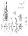
- FIG. 24 is a flowchart for over load judgment in which the connection error rate reference value and the number-of-connections reference value are set by the operator.
- NS is the number of servers
- CEi is the connection average time reference value for server i
- cni is the number of connections for server i
- CNi is the number-of-connections reference value for server i
- OLi is the over-load flag for server i.
Description
- The present invention relates to the balancing of the service load on a network server.
- More specifically, the present invention relates to a network server load balancing device (control device), a network server load balancing method, and a network server load balancing program, which allow the network service load to be distributed dynamically and efficiently to each of multiple network servers according to its status.
- In recent years, as network services have increased with the rapid spread of the Internet and Intranets, the demand has increased for improving the performance of and permitting more efficient utilization of the client server system and increasing the stability of services provided by servers. In particular, there is a demand for an environment which avoids the need for centralized access to a WWW (World Wide Web) server and which is failure-tolerant. For this reason, a system has been provided which uses two or more servers (or nodes) to perform one service (for example, ftp (file transfer protocol), HTTP (Hyper Text Transfer Protocol), telnet, or the like).
- In order to implement services stably, it is required to distribute the load on (services performed by) each server appropriately. On the other hand, the network services have become increasingly diversified, complicated, and advanced, and the frequency at which changes are made to the configuration of a group of servers and the service distribution method has increased. Also, the demand has increased for circumventing interruptions of service due to some servers going down unexpectedly.
- Existing techniques of distributing services among multiple servers include:
- (a) Round-robin DNS (Domain Name Server): in the DNS service, an entry table is set up in which multiple server IP (Internet Protocol) addresses are mapped to one domain name. When an inquiry is made by a client about a server IP address, servers are allocated to the client on a round robin basis according to the entry table and IP addresses of the allocated servers are presented to the client, thereby distributing services among multiple servers.
- (b) Load distribution hardware: a hardware device is placed between a server group and a network to relay communications between clients and servers. Load measuring communications are made between the hardware device and each server and packets to be relayed are monitored to measure the number of connections to each server and its response time, thereby detecting the load condition of each server and distributing services among the servers accordingly.
- (c) Agent: a function, called an Agent, which resides on each server in a server group, measures the load on the server's CPU (Central Processing Unit) and its disk utilization to see its load condition. The load distribution system is notified of the load condition of each server and distributes services to the servers accordingly.
- However, the conventional techniques have the following problems:
- Round robin DNS: in this system, services are distributed to servers only equally or in simple rations and each server has thus to perform services allocated to itself irrespective of its capabilities and dynamic load conditions. This produces a difference in load condition between each server, resulting in reduced efficiency of the whole system. Further, in the event that a server has gone down and the configuration of the server group has to be modified accordingly, it is required to change the server group configuration by manually deleting the server that went down from the entry table. This change is made each time a server goes down. It is therefore difficult to cope with such a situation immediately. As a result, the whole system will have to be stopped temporarily.
- Load distribution hardware: this system uses additional hardware and hence its introduction is costly. The scope for employing this system is limited because in practice, the necessary hardware will not be incorporated into each server. In addition, since communications for load measurement are always needed between each server, extra load, over and above the original communications, is imposed on each server, which further increases traffic and may cause servers to go down. Furthermore, since the load is measured on a packet-by-packet basis, the servers may be switched even in mid-service and consequently errors may occur.
- Agent: since the agent function resides on each server, the server has to be modified at the time the function is installed and moreover the agent must conform to the server's operating system (OS). In addition, load measurements are made continually for each server, resulting in a further increase in the load on the server. Furthermore, as is the case with the load distribution system, since the load is measured on a packet-by-packet basis, the servers may be switched even in mid-service and consequently errors may occur.
-
EP-A-0 648 038 discloses a control device, a method and a program according to the preamble of each independent claim. According to this prior art, the client computer ("first control unit" of the claims of the present application) does not use the physical address of each sever ("second control unit") in a cluster, but rather a generic server computer name. Decision logic in the control device decides, on the basis of test criteria related to the load on each server and considered periodically, which physical server to associate with the generic server computer name. - Hence when the client computer requests a machine address for the generic server computer name, the control device accesses a list held in a memory and identifies a machine address just as it would if any other server computer name had been given. However in this instance the machine address actually relates to the server computer in the cluster which has been identified by the decision logic as the most suitable (e.g. least heavily loaded). When this machine address is passed back to the client computer, the client computer will proceed to automatically access the server which is most suitable.
- Since only a single server in the cluster is associated with the generic server computer name at any time, the above approach has limitations when many network services are being provided to different clients at the same time.
- Embodiments of the present invention can provide a network server load balancing device and method, and a computer-readable recording medium storing a network server load balancing program, which permit changes in the server group configuration and server statuses to be accommodated instantly, permit the changes to be reflected on a client instantly, require no modification of the servers at installation time, and permit various implementations to be accommodated flexibly.
- According to a first aspect of the present invention, there is provided a network load balancing device for receiving packets of data sent via a network from a first control unit acting as a client towards a plurality of second control units acting as servers, each packet having a header including a client address that represents the first control unit and a group address that represents the second control units, said network load balancing device comprising:
- conversion information storing means for storing conversion information for use in determining which of the second control units is to provide services for the first control unit, said conversion information storing means being arranged to store a conversion table composed of a plurality of slots, each slot accessible by a respective index and containing server information;
- distributed ratio adjusting means for adjusting the information contained in the conversion table; and
- load measuring means for measuring loads on each of the second control units and notifying the distribution ratio adjusting means of load conditions of the second control units to thereby allow the distribution ratio adjusting means to adjust the information stored in the conversion table;
- said network load balancing device being arranged to receive a packet from said first control unit, to extract the header and derive therefrom an index to identify a slot in the conversion table, and to determine a second control unit which is to provide services to the first control unit from the server information in the slot;
- The control device may be provided as part of a computer network together with the first control unit (client) and the plurality of second control units (servers).
- According to a second aspect of the present invention, there is provided a network load balancing method for use with a system in which packets of data are transferred between a first control unit acting as a client and a plurality of second control units acting as servers, said network load balancing method comprising the steps of, in a network load balancing device:
- storing conversion information, in the form of a conversion table composed of a plurality of slots, each slot accessible by a respective index and containing server information, for use in determining which of the second control units is to provide services to the first control unit;
- receiving a packet from said first control unit, extracting a header and deriving therefrom an index to identify a slot in the conversion table, and determining a second control unit which is to provide services to the first control unit from the server information in the slot; and
- measuring the load on each of the second control units and adjusting the conversion information according to the load conditions of each of the second control units;
- relaying the packets of data sent by the first control unit to the second control unit thus determined according to the conversion information stored by the storing conversion information step;
- said relaying step including providing a conversion table in the form of a pattern hash table, obtaining the index of a slot in the pattern hash table by applying a hash function to a pattern obtained by masking the packet header, identifying structured data having the same pattern in the conversion table by means of pattern matching, converting the pattern to an index to identify a slot, determining one of said second control units to which the packet is to be directed from the server information that the slot holds, and sending the packet to that one of the second control units; and
- said measuring step including monitoring the packets relayed in said relaying step.
- According to a third aspect of the present invention, there is provided a network load balancing program for carrying out the above method.
- The present invention will be more apparent from the following detailed description, when taken in conjunction with the accompanying drawings, in which:
-
FIG. 1 is a schematic representation of the present invention; -
FIG. 2 is a block diagram of a system configuration of the present invention; -
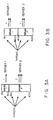
FIG. 3A shows an example of hash function-based distribution of services to servers; -
FIG. 3B shows another example of hash function-based distribution of services to servers; -
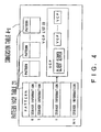
FIG. 4 shows an arrangement of the conversion table shown inFIG. 2 ; -
FIG. 5 is a flowchart illustrating to which server a packet is transferred; -
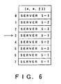
FIG. 6 shows an example of a pattern hash table; -
FIG. 7 is a diagram for use in explanation of the use of the pattern hash table having a VCP list; -
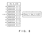
FIG. 8 is a diagram for use in explanation of the use of the pattern hash table having a VCP list; -
FIG. 9 is a diagram for use in explanation of the use of the pattern hash table having a VCP list; -
FIG. 10 is a diagram for use in explanation of the use of the pattern hash table having a VCP list; -
FIG. 11 is a flowchart for load measurement; -
FIGs. 12 and13 are a flowchart for load balancing; -
FIG. 14 is a flowchart for judgment of over load; -
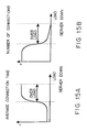
FIG. 15A is a diagram for use in explanation of over-load judgment based on the average connection time; -
FIG. 15B is a diagram for use in explanation of over-load judgment based on the number of connections; -
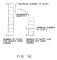
FIG. 16 is a diagram for use in explanation of a variation in the number of slots; -
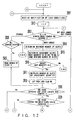
FIG. 17 is a flowchart for determination of upper and lower limit values for the number of slots; -
FIG. 18 is a flowchart for judgment of "server stop" due to over load; -
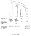
FIG. 19 is a diagram for use in explanation of variations in the number of slots; -
FIG. 20 is a flowchart for judgment of over load; -
FIG. 21 is a flowchart for judgment of over load; -
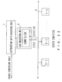
FIG. 22 is a block diagram for load measurement using a dummy client; -
FIG. 23 is a flowchart for judgment of over load; -
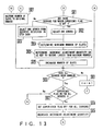
FIG. 24 is a flowchart for judgment of over load; -
FIG. 25 is a flowchart for determining servers whose measured values differ from the average measured value by an arbitrary value; -
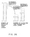
FIG. 26 is a diagram for use in explanation of variations in the number of slots; -
FIG. 27 is a flowchart for allocating the slots to each server according to the conversion table; -
FIG. 28 is a block diagram of the failure monitor ofFIG. 2 ; -
FIG. 29A shows another system configuration; -
FIG. 29B shows still another system configuration; -
FIG. 29C shows a further system configuration; and -
FIG. 30 shows an implementation of the present invention using a recording medium. -
FIG. 1 is a conceptual diagram of the present invention. - The inventive device has a group address, vip, that represents multiple servers, and a client sends packets to vip. Packet transfer is made by changing the destination of the packets from the vip to the server's address. The main operation of packet transfer includes receiving a packet, masking its header to obtain a pattern (mask(head) → pat), converting the pattern, pat, into an index in a conversion table using a hash function (hash(pat) → ix), changing the destination of the packet from vip to ip where ip is a destination address corresponding to the address of a server that a slot, ix, in the conversion table has, and sending the packet to that server. For load measurement, the connection time is measured through processing of sending packets to the server. A total quantity of connection time is computed from the start of the measurement (the previous measured values are reset), and the number of connections is incremented.
- The network service server load balancing device of the present invention distributes packets from a client to servers in accordance with the contents of the conversion table. The conversion table is updated so that the distribution ratio of packets to each server will be converged dynamically to the optimum one according to the load and failure conditions of the respective servers.
-
FIG. 2 is a block diagram of a system configuration of the present invention. - A first embodiment of the present invention is directed to a network load balancing device which, for use with a system in which data is transferred from a first control unit to a plurality of second control units over a network, comprises a conversion information storage unit which stores conversion information that represents a correspondence relationship of the first control unit to the second control units, a distributive relay unit which transfers data from the first control unit to one or more of the second control units on the basis of the correspondence relationship stored in the conversion information storage unit, a distribution ratio adjusting unit which adjusts the correspondence relationship information stored in the conversion information storage unit, and a load measurement unit which measures the load conditions of the respective second control units and notifies the distribution ratio adjusting unit of the measured load conditions to allow the balancing unit to balance the correspondence relationship of the first control unit to the second control units.
- In
FIG. 2 , reference numerals 1-1, 1-2, .., 1-m denote client computers available to users, which receive services from server computers 5-1, 5-2,..., 5-n over anetwork 2 and a network service serverload balancing device 3. Thenetwork 2 is the Internet, an intranet, a local area network (LAN), or a wide area network (WAN).Reference numeral 11 denotes a network which is made up by a group of the server computers 5-1, 5-2, .., 5-n.Reference numeral 3 denotes a network service server load balancing device which is composed of adistributive relay unit 4, a conversion table 4-a, aload measurement unit 6, a distributionratio adjusting unit 7, afailure monitor unit 8, acontrol unit 9, and astatus management unit 10. Thebalancing unit 3 has virtual addresses vip_1, vip_2,..., vip_1 and, when a client makes access to the address vip_i (1 ≤ i ≤ 1), allows the servers 5-1, 5-2,..., 5-n to look like a single computer having the address vip_i. Thedistributive relay unit 4 relays communications between the clients 1-1, 1-2,..., 1-m and the servers 5-1, 5-2, .., 5-n. More specifically, the relay unit receives a packet having the destination address vip i from one of the clients, masks its header (containing the IP address of the client itself, a port number representing the type of a service such as ftp, HTTP, telnet, or the like, the IP address of the destination server, etc.) to obtain a pattern, identifies structured data having the same pattern in the conversion table 4-a for vip_i by means of pattern matching, converts the pattern to an index to identify a slot, determines a server to which the packet is to be directed from server information that slot holds, and sends the packet to the server thus determined. The details of the conversion table 4-a will be described later. Theload measurement unit 6 measures the load on each of the servers. More specifically, the load measuring unit monitors packets the distributive relay unit relays, measures the load conditions, such as the average connection time and the number of connections per unit time, for each of the servers, and presents the measurements to the distributionratio adjusting unit 7 at regular intervals. The balancing unit detects the stop of a server depending on whether its measurement indicates an abnormal value and detects over loaded servers using a reference value. In response to stopped-server notification from thefailure monitor unit 8 or an instruction from thecontrol unit 9, the balancing unit recomputes the service distribution ratio when over-doped servers or stopped servers are detected or as instructed by the user and updates the conversion table 4-a accordingly. Thefailure monitor unit 8 performs a polling command, such as ping, on each server at regular intervals and considers servers that caused a certain number of time-outs to be in the stopped state. This information is presented to the distributionratio adjusting unit 7. Thecontrol unit 9 controls the network service serverload balancing unit 3 in its entirety as instructed by the user. More specifically, the control unit starts or stops theload measurement unit 6, the distributionratio adjusting unit 7, and thefailure monitor unit 8 and retains and restores the information set in the conversion table 4-a. Thestatus management unit 10 retains information set in the conversion table 4-a and the network serviceserver balancing unit 3 in a file and restores it. More specifically, the status management unit retains information set in the conversion table 4-a and the network service serverload balancing unit 3 in a file when the distribution ratio adjusting unit is stopped and additions are made to servers and services or when a command is given by the user. When the distribution ratio adjusting unit is started and the servers or services are restored or when a command is given by the user, the status management unit restores the information, provided that the server group configuration is the same as before the distribution ratio adjusting unit is stopped or before the servers or services are stopped. - Since the load conditions of the servers that make up a network are measured and packets from clients are sent to the servers according to the load conditions of each client, well-balanced, efficient services can be provided. Moreover, since it is known which server a sequence of packets is being sent to, no server switching occurs in the middle of a sequence of services. Furthermore, since there is no need of flowing data dedicated to load balancing on communication paths, the paths can be employed for services only.
- How to distribute packets sent by the clients to the servers in the above arrangement and how to converge the distribution ratio of the packets to the servers dynamically to the optimum state will be described separately.
- A second embodiment of the present invention is directed to a network load balancing device characterized in that the load measuring unit measures the load on the basis of the average time of connecting data to each second control unit and the number of connections of data to the second control unit per unit time.
- First, how to distribute packets sent by clients to the servers will be described.
- As shown in
FIGs. 3A and 3B , if a hash function can distribute indexes uniformly, then the service distribution ratio to the servers becomes equal to the ratio of the numbers of slots assigned to the servers in the conversion table. - As an example, if, as shown in
FIG. 3A , the conversion table has 256 slots (numbered 0 to 255), andserver 1 andserver 2 are assigned 64 slots and 192 slots, respectively (consecutive slots need not necessarily be assigned to each server), then services will be distributed toserver 1 andserver 2 at a ratio of 1 : 3. Thus, the service distribution ratio can be changed by changing the number of slots assigned to each server. If, as shown inFIG. 3B , 64 slots of 192 slots assigned toserver 2 are assigned toserver 1, then the ratio of the number of slots assigned toserver 1 to that assigned toserver 2 will become one to one (1 : 1) and the service distribution ratio will also become one to one (1 : 1). -
FIG. 4 shows an arrangement of the conversion table. - The conversion table 4-a is one referred to as a pattern hash table 21 that is structured data composed of one or more slots each accessible by an index obtained by applying a hash function to a pattern obtained by masking a packet header. Data additions or deletions can be made to or from the conversion table at the time of system operation. Each slot contains information which can identify one of the servers 5-1, 5-2,..., 5-n and a VCP (Virtual Circuit Preservation)
list 22 which holds client-server information in a service being relayed through that slot. Since the service distribution ratio can be controlled by the ratio of numbers of slots assigned, it follows that the more slots a server is assigned, the more services it will be assigned. -
FIG. 5 is a flowchart illustrating which server a packet is transferred to. - First, in step S301, the network service server
load balancing unit 3 receives a packet sent from a client. In step S302, thedistributive relay unit 4 obtains a pattern of the header of the received packet. The pattern of the header is a set of bit streams obtained by masking the packet header and takes the form of, for example, (cip_1, cpo_1, 23). Here, cip_1 is the client IP address, cpo_1 is the client port number, and 23 is the service port number. In step S303, thedistributive relay unit 4 searches through the pattern hash table in the conversion table 4-a for a pattern that matches the pattern (cip_1, cpo_1, 23). For example, such a pattern (*, *, 23) as shown inFIG. 6 is obtained. This pattern matches a pattern of an arbitrary IP address, an arbitrary port number, and theservice port number 23. Next, in step S304, a hash function is applied to the pattern obtained in step S302. In step S305, the solution is obtained. For the hash function, the remainder of the division by 8 is set as the solution. It is assumed here that the solution [3] was obtained. This means thatslot 3 was selected inFIG. 6 . Inslot 3, server 5-1 is set as server information. - Next, in step S306, a decision is made as to whether the received packet is the first one of a sequence of packets. A sequence of packets is packets in which a client having the same client IP address cip_1 requests the same client port cpo_1a for a service of the same
service port number 23. Whether the received packet is the first one of a sequence of packets depends on whether the VCP list ofslot 3 contains VCP (cip_1, cpo_1, 5-1). If that packet is the first one, theVCP list 22 does not contain VCP (cip_1, cpo_1, 5-1). In step S307, therefore, VCP (cip_1, cpo_1, 5-1) is created in theVCP list 22. In step S308, the created packet is sent to the server 5-1. If, in step S306, the VCP list contains VCP (cip_1, cpo_1, 5-1), that is, if packets in which a client having the same client IP address cip_1 requests the same client port cpo_1 for a service of the sameservice port number 23 are being transferred, that packet is transferred to the server 5-1 identified by VCP (cip_1, cpo_1, 5-1) in theVCP list 22. - Next, in step S310, a decision is made as to whether this packet is the last one. If it is, VCP (cip_1, cpo_1, 5-1) is deleted from the
VCP list 22. - Reference will be made to
FIGs. 5 through 10 to describe how four packets will be transferred to a server in a state where no packet is received. To simplify the description, it is assumed that these packets contain the same client IP address cip_1, the same client port cpo_1, and the sameservice port number 23. Steps S301 to S305 inFIG. 5 are assumed to be the same for all the packets. That is, it is assumed that the pattern in the pattern hash table that matches the packet pattern is (*, *, 23) and the hash value of the packet pattern is 3, i.e., the slot number is 3. - First, packet 1 (cip_1, cpo_1, 23) is sent by the client 1-1. Since the VCP list contains nothing (S306,
FIG. 6 ), VCP (cip_1, cpo_1, 5-1) is created (S307,FIG. 7 ), andpacket 1 is transferred to the server 5-1 (S308) identified inslot 3. After that, the server information inslot 3 is assumed to have been updated from 5-1 to 5-2 by the distributionratio adjusting unit 7. This updating will be described later. Next, packet 2 (cip_1, cpo_1, 23) is sent by the client 1-1 that sentpacket 1.Packet 2 is transferred to the server 5-1 (S309) since the VCP list contains VCP (cip_1, cpo_1, 5-1) though the server information inslot 3 has been updated to server 5-2 (S306,FIG. 8 ). Thatpacket 2 is transferred to the server 5-1 as opposed to the server 5-2 means that the interruption of the service being processed is prevented. Next, packet 3 (cip_2, cpo_2, 23) is sent by the client 1-2. The VCP list contains no VCP information about the client 1-2 (S306,FIG. 8 ). Thus, VCP (cip_2, cpo_2, 5-2) is added to the VCP list (S307,FIG. 9 ) andpacket 3 is then transferred to the server 5-2 specified in the slot 3 (S308). Finally, packet 4 (cip_1, cpo_1, 23) is sent by the client 1-1. Thispacket 4 is assumed to be the last one. Since the VCP list contains VCP (cip_1, cpo_1, 5-1) (S306,FIG. 9 ),packet 4 is transferred to the server 5-1 (S309). Since this packet is the last one (S310), VCP (cip_1, cpo_1, 5-1) is deleted from the VCP list (S311,FIG. 10 ). - As described above, VCP information is added to the slot VCP list at the commencement of service and maintained until the service is terminated. At the time of access to a slot, the VCP list the slot has is examined. If an incoming packet is one for a service in process, then it will be delivered to a server already specified in the VCP list. Therefore, it becomes possible to prevent an interruption of the service in process even when a change is made to server information that a slot holds at the service distribution ratio control time.
- The more slots the server is assigned, the more services it is assigned. Thus, the service distribution ratio can be controlled by the ratio of the numbers of slots assigned to the servers. When a server is over loaded, the average connection time becomes long and the number of connections decreases, which is employed as the criterion for judging whether a server is over loaded. It therefore becomes possible to circumvent a misjudgment of over loading as made when the number of connections to a server increases temporarily or connection itself is little made to it.
- A third embodiment of the present invention is directed to a network load balancing device which is characterized in that the distribution ratio adjusting unit judges the level of the load on each second control unit on the basis of the average time of connection of data to it and the number of connections of data to it and balances the load on each second control unit by adjusting the ratio of distribution of data to the second control units.
- How to converge the distribution ratio to the servers dynamically to the optimum value, in other words, how to change the conversion table 4-a so that the distribution ratio to the servers will be converged dynamically to the optimum value according to the load conditions and the failure conditions of the servers will be described below.
-
FIG. 11 is a flowchart for measurement of the load on each server. - In step S111, the
load measurement unit 6 measures the load on each of the servers. The load measurement is made based on measured values at the packet transmission time. Thus, since there is no need for communications and server's processing (load measurement and notification), the inventive device can be installed and operated without affecting the servers. For load measurement, the following set of operations is repeated. That is, the set of operations comprises resetting the previous measurements, waiting for n seconds, acquiring measurements (the total of connection time and the number of connections), and notifying the distributionratio adjusting unit 7 of the measurements acquired. As the load on each server, use is made of the connection average time and the number of connections per unit time, which are obtained from the measured time interval between the moment that a connect request signal is sent to the server and the moment that a connect completion signal is received from the server prior to the transmission of packet data. - In step S112, the
load measurement unit 6 notifies the distributionratio adjusting unit 7 of those results. -
FIGs. 12 and13 are a flowchart for load balancing. - In step S911, the distribution
ratio adjusting unit 7 receives notification of load conditions from theload measurement unit 6 and then performs load balancing described below. - In step S912, the initial value of a variable i is set to 1 in order to perform load balancing starting with the first server. In step S913, a decision is made as to whether the first server is over loaded or stopped. In the example of the above-described load measurement, a server for which the connection average time per unit time is longer than a reference connection average time and the number of connections per unit time is less than a reference number of connections is considered to be under over load (
FIGs. 15A and 15B ), which is illustrated in a flowchart ofFIG. 14 . - In
FIG. 14 , NS is the number of servers, cti is the connection average time for server i, CTi is the reference connection average time for server i, cni is the number of connections for server i, CNi is the reference number of connections for server i, and OLi is the over load flag for server i which is set ON when it is over loaded.FIG. 15A shows a connection average time versus load characteristic of a server, which illustrates that the connection average time increases because the connection time contains a long time-out period due to connection failures when connection processing cannot overtake connection requests because of over load conditions and thus the number of connection failures increases. The connection average time is obtained from the total connection time and the connection time.FIG. 15 shows a number of connections versus load characteristic, which illustrates that the number of connections per unit time decreases as the connection time becomes longer. The over load judgment is made on the basis of the two above-described features which can be observed when a server enters the over load state. The reason why two indexes of the connection average time and the number of connections are used is to prevent misjudgment based on the following two points. The first point is that, since the number of connect requests the servers can accept simultaneously is limited, when more connect requests than the server can accept occurs, the connection average time becomes long even if the servers are not in the over load state. This means that the number of connections the severs can accept simultaneously is a bottleneck. The number of connections becomes a maximum value or so. The other point is that, when the number of service requests (connect requests) to servers reduces, the number of connections also reduces proportionally. That is, the load on the servers decreases because of a small number of requests. Therefore, the use of both the connection average time and the number of connections permits the load judgment to be made correctly. - The connection average time reference value and the number-of-connections reference value used here are assumed to be the minimum connection average time per unit time and the maximum number of connections per unit time, respectively, which have been obtained so far. This is based on the fact that for a server which is in the over load state the connection average time increases and the number of connections decreases. By the use of both the connection average time and the number of connections for load judgment, it becomes possible to circumvent misjudgment that might occur if the number of connections to servers exceeded temporarily the number the servers can accept simultaneously or the number of connect requests by clients decreased.
- In step S914, for the server considered to be over loaded, the number of slots set in the conversion table 4-a for that server is set as the maximum number of slots (
FIGs. 16 and17 ). InFIG. 17 , OLi is the over load flag for server i, OLHi is the over-load experience flag for server i, SLTi is the number of slots for server i, MAXi is an upper limit on the number of slots for server i, MINi is a lower limit on the number of slots for server i, and n is a quantity of adjustment for the number of slots. - For a server considered to be over loaded, the number of slots set in the pattern hash table in the conversion table 4-a for that server is decreased by a decrement adjustment quantity in step S917. The decrement adjustment quantity, indicating the number of slots to be decreased, has been determined in step S915. The decrement adjustment quantity, which is an integer of, for example, three, must be set so as not to become smaller than the minimum number of slots allocated for that server. After the decrement adjustment quantity has been determined, a decision is made in step S916 as to whether or not it is equal to zero. If it is not, the number of slots for that server set in the hash table in the conversion table 4-a is decreased by the decrement adjustment quantity in step S917. In step S918, the over-load experience flag for that server having its allocated slots decreased is set ON.
- Next, in step S919, a decision is made as to whether there are other servers which are not over loaded nor stopped. The criterion for this decision is the same as that in step S913. If there is no other server which is not over loaded nor stopped, then the procedure goes to step S927 to be described later. If the decision in step S919 is YES, a decision is made in step S920 as to whether or not, of the servers detected in step S919, there are servers for which the number of slots can be increased. If there are, a decision is made in step S921 as to whether or not, of the servers detected in step S920, there are servers for which the experience flag is OFF. If there are, then an arbitrary server, for example, a server which is the most lightly loaded, is selected from the servers in step S922. If there is no server for which the experience flag is OFF, then the procedure goes to step S923 in which an arbitrary server, for example, a server which is the most lightly loaded, is selected from the servers detected in step S920. In step S924, the number of slots which is set in the conversion table 4-a for that server selected in step S922 or S923 is set as the minimum number of slots (
FIG. 16 ). Next, in step S926, the number of slots set in the pattern hash table in the conversion table 4-a for that server is increased by an increment adjustment quantity, which is determined in step S925. The increment adjustment quantity, which corresponds to a decrease in the number of slots for the other server considered to be over loaded, must be set so as not to become larger than the maximum number of slots set for that other server. After the increment adjustment quantity has been determined, the number of slots set in the pattern hash table in the conversion table for that server which is the most lightly loaded is increased by the adjustment quantity in step S926. In step S930, a decision is made as to whether all the servers have been handled. - If the decision in step S919 is NO and the decision in step S920 is NO, then the procedure goes to step S927 in which the number of slots, which has been decreased in step S917, is restored to the original number. And then, a decision is made in step S930 as to whether all the servers have been handled.
- If, in step S913, the measurement of a server by the
load measurement unit 6 shows an abnormal value, it is decided that the server is stopped. After that, in step S928, a decision is made as to whether all other servers are stopped. If not all servers are stopped, then the number of slots for that server considered to be stopped is made zero in step S929. The procedure then goes to step S919 in which a decision is made as to whether there is any other server which is not over loaded nor stopped. -
FIG. 18 is a flowchart for deciding that a server is in the stopped state because of abnormality due to it being too much over loaded. In this figure, NS is the number of servers, Ci is a number-of-connections reference value for server i, and O (Ci) is a reference value optimization function. By making the number of slots for a server considered to be in the stopped state zero, service distribution to the server can be stopped and the server stopping can be hidden from clients. -
FIG. 19 shows variations in the number of slots for servers.Server 1 is one which is considered to be over loaded and for which the experience flag is ON. The number of slots is decreased by n.Server 2 is one which is considered to be over loaded and for which the experience flag is OFF. The experience flag is set ON and the number of slots is decreased by m.Server 3 is one which, although its experience flag is ON, is not considered to be over loaded.Server 4 is one which is not considered to be over loaded and for which the experience flag is OFF. Thus, the number of slots forserver 4 is incremented by n + m where n and m are decrements in the number of slots forservers - If, in step S913, it is decided that a server is not over loaded nor stopped, then the procedure goes to step S930 in which a decision is made as to whether or not all the servers have been handled. If all the servers have not been handled, the variable i is incremented in step S931. The procedure then returns to step S913 to handle the next server.
- Next, in step S932, a decision is made as to whether or not the over-load experience flag is ON for all the servers. In the presence of at least one server for which the over-load flag is not ON, return is made to step S911 to receive the load measurements. If the experience flag is ON for all the servers, it is returned to OFF for all the servers. In step S935, the decrement adjustment value, the initial value of which has been set to three in the previously described example, is changed to a proper value, for example, two, which is obtained by decrementing the initial value by one. The procedure then returns to step S911 to receive the load measurements.
- That, in step S932, the over-load experience flag is ON for all the servers means that all the servers have undergone an adjustment of the number of slots. Further, the adjustment width becomes decreased by decreasing the decrement adjustment quantity In step S935. This means that the adjustment gradually converges in a limited number of times. The load on each server can be made to approach an optimum value.
- The more slots the server is assigned, the more services it receives. Thus, the service distribution ratio can be controlled by the ratio of the numbers of slots assigned to the servers. When a server is over loaded, the connection average time increases and the number of connections to servers decreases, which is employed to detect the over-load state of the server. It therefore becomes possible to circumvent a misjudgment of over load as made when the number of connections to servers increases temporarily or connection itself is little made.
- A fourth embodiment of the present invention is directed to a network load balancing device which is arranged as follows:
- The conversion information storage unit includes a table in which a correspondence relationship of the first control unit to the second control units is established and a unit that maintains the correspondence relationship between the first control unit and the second control units throughout transmission of a sequence of packets. The distribution ratio adjusting unit comprises a unit that, when the measurement of the load on each second control unit shows an abnormal value, judges that it is in the stopped state, a unit that compares the connection average time and the number of connections for the second control unit with the connection average time reference value and the number-of-connections reference value which are the minimum connection average time and the maximum number of connections for the second control units, respectively, and considers a second control unit as over loaded for which the connection average time is sufficiently larger than the corresponding reference value and the number of connections is sufficiently smaller than the corresponding reference value, a unit that manages the service distribution ratio to the second control units as numbers allocated to the second control units. This management unit comprises a stopped state management unit that, in the presence of a second control unit considered to be in the stopped state, distributes the allocated number of that second control unit to second control units which are not in the stopped state at the ratio of the allocated numbers of those second control units, and a over load management unit that decreases the allocated number of a second control unit considered to be over loaded and increases the allocated numbers of second control units which are not over loaded. This over load management unit includes a unit that decreases the incremental or decremental value of the allocated numbers of the second control units with each adjustment cycle to thereby converge the service distribution ratio. The load measuring unit includes a unit that periodically measures the connection average time and the number of connections per unit time for each second control unit on the basis of data relayed to it and notifies the distribution ratio adjusting unit of the statuses of the second control units.
- The more slots the server is assigned, the more services it receives. Thus, the service distribution ratio can be controlled by the ratio of the numbers of slots assigned to the servers. When a server is over loaded, the connection average time increases and the number of connections to the server decreases, which is employed to detect the over-load state of each server. It therefore becomes possible to circumvent a misjudgment of over load as made when the number of connections to a server increases temporarily or connection itself is little made.
- A fifth embodiment of the present invention is directed to a network load balancing device which further includes a status management unit which preserves the status before adjustment and restores the status to the original status at recovery time.
- The more slots the server is assigned, the more services it receives. Thus, the service distribution ratio can be controlled by the ratio of the numbers of slots assigned to the servers. When a server is over loaded, the connection average time increases and the number of connections to the server decreases, which is employed to detect the over-load state of each server. It therefore becomes possible to circumvent a misjudgment of over load as made when the number of connections to a server increases temporarily or connection itself is little made.
- A sixth embodiment of the present invention is directed to a network load balancing device which is arranged as follows:
- The conversion information storage unit includes a table in which a correspondence relationship of the first control unit to the second control units is established and a unit that maintains the correspondence relationship of the first control unit to the second control units throughout transmission of a sequence of data packets. The distribution ratio adjusting unit comprises a unit that, when the measurement of the load on each second control unit shows an abnormal value, judges that it is in the stopped state, and a stopped state management unit that manages the distribution ratio to the second control units as the allocated numbers for the second control units in the conversion information and, in the presence of a second control unit considered to be in the stopped state, distributes the allocated number of that second unit to second control units which are not in the stopped state at the ratio of the allocated numbers of those second control units.
- The more slots the server is assigned, the more services it receives. Thus, the service distribution ratio can be controlled by the ratio among the numbers of slots assigned to the servers. When a server is over loaded, the connection average time increases and the number of connections to the server decreases, which is employed to detect over loading of the server. It therefore becomes possible to circumvent a misjudgment of over load as made when the number of connections to a server increases temporarily or connection itself is little made.
- Although the flow of load measurement and the flow of load balancing have been described in terms of several steps, other examples of these steps will be described next.
- A seventh embodiment of the present invention is directed to a network load balancing device which is arranged as follows:
- The load measuring unit includes a unit that measures the number of connection errors and the number of connections per unit time for each second unit on the basis of data relayed to it and notifies the distribution ratio adjustment unit of the measurements at regular intervals. The distribution ratio adjusting unit further comprises a unit that, when the measurement of the load on each second control unit shows an abnormal value, judges that it is in the stopped state, compares the connection error rate and the number of connections for each second control unit with a connection error rate reference value and a number-of-connections reference value which are the minimum connection error rate, which is represented by the ratio of the number of connection errors to the number of connections, and the maximum number of connections for the second control units, respectively, and considers a second control unit as over loaded for which the connection error rate is sufficiently larger than the corresponding reference value and the number of connections is sufficiently smaller than the corresponding reference value.
- In step S111 of
FIG. 11 , theload measurement unit 6 measures the time interval between the time of transmission of a connect request signal to a server and the time of reception of a connect complete signal from it prior to transmission of packet data and uses, as the measurements of the load on it, the connection average time and the number of connections per unit time which are sought from the measured time interval. As an alternative, it may be arranged to detect connection errors for the connect request signal and use the connection error rate (the ratio of the number of connection errors detected to the number of connections) and the number of connections per unit time. In this case, the criterion for considering a server to be over loaded in step S913 is that the connection error rate per unit time is higher than a connection error rate reference value and the number of connections per unit time is smaller than a number-of-connections reference value. The connection error rate reference value and the number-of-connections reference value used here are respectively defined to be the minimum correction error rate and the maximum number of connections per unit time, which have been obtained so far. -
FIG. 20 is a flowchart for high load judgment, which employs the connection error rate per unit time and the number of connections per unit time as the criterion in step S913 ofFIG. 12 for deciding whether a server is over loaded. In this figure, NS is the number of servers, cei is the connection average time for server i, CEi is the connection average time reference value for server i, cni is the number of connections for server i, CNi is the number-of-connections reference value for server i, and OLi is the high load flag for server i. - Since the number of connection errors and the number of connections are measured, load balancing can be made even if another route is taken between a server and a client.
- An eighth embodiment of the present invention is directed to a network load balancing device which is characterized in that the load measuring unit further includes a unit that measures the number of virtual circuits (VCs) for each of the second control units on the basis of data relayed to it and notifies the distribution adjustment unit of the measurement at regular intervals, and the distribution ratio adjustment unit further includes a unit that considers a second control unit for which the number of VCs exceeds a preset reference value to be over loaded.
- Since the number of VCs is used for over load judgment, it is possible to estimate the load on a server even in a case where the time interval between the commencement and termination of a service is long and hence the number of connections is small.
- A ninth embodiment of the present invention is directed to a network load balancing device which is characterized in that the load measurement unit measures the response time between the commencement and termination of transmission for each of the second control units on the basis of data relayed to it and notifies the distribution ratio adjustment unit of the result at regular intervals, and the distribution ratio adjustment unit further includes a unit that considers a second control unit to be over loaded for which the response time exceeds a preset reference value.
- Alternatively, in step S111 of
FIG. 11 , theload measurement unit 6 may measure the number of VCs for each second server and provide the number of VCs per unit time as the measurement of the load on it. In this case, the criterion in step S913 for considering the second sever to be over loaded is that the number of VCs per unit time is larger than a reference value for the number of VCs. The reference value used here is one that has been set in advance. -
FIG. 21 is a flowchart for over-load judgment, which employs the number of VCs per unit time as the criterion in step S913 ofFIG. 12 for deciding whether a server is over loaded. In this figure, NS is the number of servers, Pi is the number of VCs, the response average time, and the imitated service response average time for server i, Ci is the user-set reference value for server i, and OLi is the over load flag for server i. - Since the service response time is employed for over-load judgment, the real-time load judgment can be made.
- A tenth embodiment of the present invention is directed to a network load balancing device which is characterized in that the load measurement unit performs an operation determined by imitating the first control unit in data sent by each second control unit, measures the service time required to perform the operation, and notifies the distribution ratio adjustment unit of the average time, and the distribution ratio adjustment unit further includes a unit that decides that a second control unit is over loaded for which the service average time is larger than a preset reference value.
- Alternatively, in step S111 of
FIG. 11 , theload measurement unit 6 may measure the response time between the commencement and termination of a service for each server and provide the response average time per unit time as the measurement of the load on it. In this case, the criterion in step S913 ofFIG. 12 for considering the sever to be over loaded is that the response average time per unit time is larger than a response average time reference value. The reference value used here is one that has been set in advance. - In
FIG. 21 , the response average time (11-b) is employed as the criterion in step S913 ofFIG. 12 for deciding whether a server is over loaded. - Since the response time for an imitated service is used for over load judgment, load measurement that reflects a difference in characteristic between each service can be made.
- Further, in step S111 of
FIG. 11 , as a dummy client theload measurement unit 6 may perform some service operation in imitation of a client, measures the response time between the commencement and termination of the service, and provides the imitative service response average time as the load measurement, as shown inFIG. 22 . In this case, the criterion in step S913 ofFIG. 12 for considering the sever to be over loaded is that the imitative service response average time per unit time is larger than an imitative service response average time reference value. The reference value used here is one that has been set in advance. - In
FIG. 21 , the imitative service response average time (11-c) is employed as the criterion in step S913 ofFIG. 12 for deciding whether a server is over loaded. - An eleventh embodiment of the present invention is directed to a network load balancing device which is characterized by further comprising a unit that allows an operator to set the reference value used in the distribution ratio adjustment unit for over load judgment.
- As described previously, In step S913 of
FIG. 12 , the minimum connection average time per unit time, the maximum number of connections per unit time, or the connection error rate per unit time, which are obtained by measurements, is used as the connection average time reference value, the number-of-connections reference value, or the connection error rate reference value. However, the inventive device may be modified such that an operator can specify these reference values. -
FIG. 23 is a flowchart for over load judgment in which the connection average time reference value and the number-of- connections reference value are set by the operator. In this figure, NS is the number of servers, cti is the connection average time for server i, CTi is the connection average time reference value for server i, cni is the number of connections for server i, CNi is the number-of-connections reference value for server i, and OLi is the over load flag for server i. -
FIG. 24 is a flowchart for over load judgment in which the connection error rate reference value and the number-of-connections reference value are set by the operator. In this figure, NS is the number of servers, cei is the connection average time for server i, CEi is the connection average time reference value for server i, cni is the number of connections for server i, CNi is the number-of-connections reference value for server i, and OLi is the over-load flag for server i. - If, since the operator sets the reference values, optimum values are known, the settings will immediately be reflected in the load measurement.
- A twelfth embodiment of the present invention is directed to a network load measurement device which is characterized in that the distribution ratio adjustment unit further comprises a unit that detects a second control unit considered to be stopped, preserves the reference values at that point, and employs the preserved reference values after recovery of the stopped server.
- The reference value, such as the connection average reference value, the number-of-connections reference value, the connection error rate reference value, the number-of-VCs reference value, the response average time reference value, or the imitative service response average time reference value, may be preserved in the
status management unit 10 on a timely basis. For example, the reference value may be preserved at the time a stopped server is detected. In this case, when the stopped server is recovered, the preserved reference value is fetched and used. - Since the reference values when a stopped server is detected are preserved, the service will not be stopped again under the same situation.
- A thirteenth embodiment of the present invention is directed to a network load measurement device which is characterized in that the distribution ratio adjustment unit further comprises a unit that determines an increment or decrement value for the number of slots allocated to a second control unit when it is considered to be over loaded according to the number of slots which has already been allocated to it at that time.
- In step S915 of
FIG. 12 , a decrement value to be determined is selected to be a preset integer of, for example, three. Alternatively, a predetermined percentage of the number of slots set in the conversion table 4-a for a server which is considered to be over loaded may be set as the decrement value. - Since the quantity of adjustment is incremented or decremented by a percentage of the number of slots allocated to a server, the quantity of adjustment will not vary greatly from server to server.
- A fourteenth embodiment of the present invention is directed to a network load balancing device which is characterized in that the distribution ratio adjustment unit further includes a unit that distributes the number of slots assigned to a second control unit when it is considered to be over loaded to all other second control units which are not over loaded according to the ratio of the numbers of slots assigned to those second control units at that time.
- The decrement value for the number of slots assigned to a server which is considered to be over loaded is determined in step S915 of
FIG. 12 . The decrement value may be updated by seeking the average value of load information and then the numbers of slots allocated for servers whose differences from the average value are greater than a predetermined value according to the ratio among their distances from the average value. -
FIG. 25 is a flowchart for load balancing operation to allow the server capabilities viewed from clients to be made constant by seeking servers whose differences are a predetermined value greater than the average measured value. In this figure, tx is the measured value for server x. - Since the adjustment quantity is incremented or decremented on the basis of the ratio among the number of slots allocated for servers which are not over loaded, the adjustment quantity will not vary greatly from server to server when there is a large difference in processing capabilities among the servers.
- A fifteenth embodiment of the present invention is directed to a network load measurement device which is characterized in that the distribution ratio adjustment unit further comprises a unit that seeks the average of the measured values of the loads on second control units and then determines the numbers of slots allocated for second control units whose measured value differ from the average by width δ according to the ratio among their distances from the average.
- The incremental quantity of adjustment for the number of slots for a server considered to be not over loaded nor stopped is determined in step S915 of
FIG. 12 . The increment quantity may be updated by seeking the numbers of slots allocated for servers whose differences from the average value of load information are greater than a predetermined value according to the ratio among their distances from the average value. - Since the server response delays viewed from clients are made constant from client to client, each client can be provided with services equally.
- In step S915 of
FIG. 12 , the incremental adjustment quantity for each server which is considered to be not over loaded or stopped may be set equal to the decremental adjustment quantity for another server considered to be over loaded (FIGs. 17 and18 ). - In step S915 of
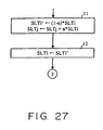
FIG. 12 , the incremental adjustment quantities for servers considered to be not over loaded or stopped may be determined according to the numbers of slots allocated for those servers in the conversion table 4-a as shown inFIG. 26 . -
FIG. 27 is a flowchart for allocating slots for servers according to the number of slots allocated for them in the conversion table 4-a. - A sixteenth embodiment of the present invention is directed to a network load balancing device which is characterized by further comprising a failure monitor unit that performs a ping command to each second unit at regular intervals, decides that a second unit which causes a certain number of time-outs is in the stopped state, and notifies the distribution ratio adjustment unit of it.
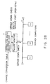
- In step S913 of
FIG. 12 , a server for which the measurement by theload measurement unit 6 indicates an abnormal value is considered to be stopped. Afailure monitor unit 8 that performs a ping command to each second unit at regular intervals, decides that a second unit which causes a certain number of time-outs is in the stopped state, and notifies the distribution ratio adjustment unit of it may be provided separately as shown inFIG. 28 . Of course, the server stop judgment by theload measurement unit 6 and the server stop judgment by thefailure monitor unit 8 may be used in combination. - Thereby, the accuracy of the detection of server stops is increased.
- A seventeenth embodiment of the present invention is directed to a network load balancing device which is characterized in that the failure monitor unit further includes a unit that tries whether it is possible to open a service port to transmit information from each second control unit, deciding, after a certain number of failures, that the transmit information is being stopped, and notifies the distribution ratio adjustment unit.
- As shown in
FIG. 28 , thefailure monitor unit 8 may be arranged to, in addition to a ping command, try whether it is possible to open a service port to a server service and decide, after a certain number of failures, that the service is in the stopped state. - Since stops on the application layer can be detected, the hiding and maintenance of failures can be performed on a service-by-service basis.
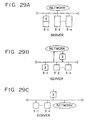
- The present invention has been described so far in terms of one form, that the network service server
load balancing device 3 receives packets from the clients 1-1, 1-2,.., 1-m over thenetwork 2, then transfers them to the servers 5-1, 5-2,.., 5-n, and receives services from the servers, then return them to the clients over the network. The network service serverload balancing device 3 may be employed in other forms: it is placed on one of the servers as shown inFIG. 29A ; the device is used to send packets from the clients to servers, but not used to return services from the servers to the clients as shown inFIG. 29B ; and the device also accommodates another network as an object of load balancing as shown inFIG. 29C . - An eighteenth embodiment of the present invention is directed to a network load balancing device characterized in that one second control unit includes the network load balancing unit.
- Thus, there is no necessity of addition of a new hardware device at the time the system is installed.
- A nineteenth embodiment of the present invention is directed to a network load balancing device which further includes another communication path directed from the second to the first control unit in addition to the communication path that passes through the network load balancing device.
- Thereby, the overall processing efficiency of the third control unit can be increased.
- A twentieth embodiment of the present invention is directed to a network load balancing device characterized by further comprising a unit consisting of a group of the second control units of multisegment configuration to which another network is connected.
- Thereby, it becomes possible for the third control unit to make load balancing over the entire network. The load balancing can be made using the present flow of data. The load will not be increased due to load measurement.
- A twenty-first embodiment of the present invention is directed to a network load balancing device characterized in that the first control unit is a client computer connected to a network, the second control units are server computers connected to the network, and the conversion information storage unit is a conversion table from the first control unit to the second control units.
- Well-balanced efficient services can be provided because the load on each of servers that make up a network is measured and packets are sent from a client to servers according to the load condition of each server. Further, no server switching occurs in the middle of a sequence of services because it is known which server a sequence of packets is sent to.
- A twenty-second embodiment of the present invention is directed to a network load balancing method, for use with a system in which data is transferred from a first control unit to a plurality of second control units over a network, which comprises: a conversion information storing step of storing conversion information which represents a correspondence relationship of the first control unit to the second control units; a distributive relay step of transferring the data sent by the first control unit to one or more of the second control units according to the correspondence relationship in the conversion information stored by the conversion information storing step; and a distribution ratio adjusting step of adjusting the correspondence relationship in the conversion information stored by the conversion information storing step; a load measuring step of measuring the load on each of the second control units and adjusting the correspondence relationship in the conversion information according to the load conditions of the second control units.
- Well-balanced efficient services can be provided because packets are sent from a client to servers according to the load condition of each server. Further, no server switching occurs in the middle of a sequence of services because it is known which server a sequence of packets is being sent to.
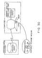
- A twenty-third embodiment of the present invention is directed to a computer-readable storage medium for use with a system in which data is transferred from a first control unit to a plurality of second control units over a network, which is recorded with a load balancing program which allows a computer to perform; a conversion information storing step of storing conversion information which represents a correspondence relationship of the first control unit to the second control units; a distributive relay step of transferring the data sent by the first control unit to one or more of the second control units according to the correspondence relationship in the conversion information stored by the conversion information storing step; and a distribution ratio adjusting step of adjusting the correspondence relationship in the conversion information stored by the conversion information storing step; a load measuring step of measuring the load on each of the second control units and adjusting the correspondence relationship in the conversion information according to the load conditions of the second control units.
- Well-balanced efficient services can be provided because packets are sent from a client to servers according to the load condition of each server. Further, no server switching occurs in the middle of a sequence of services because it is known which server a sequence of packets is being sent to.
- A twenty-forth embodiment of the present invention is directed to a network load balancing system which comprises a first control unit which sends data, a plurality of second control units which receives the data, and a third control unit which transfers the data sent by the first control unit to the second control units. The third control unit comprises: a conversion information storing unit for storing conversion information which represents a correspondence relationship of the first control unit to the second control units; a distributive relay unit for transferring the data sent by the first control unit to one or more of the second control units according to the correspondence relationship in the conversion information stored in the conversion information storing unit; and a distribution ratio adjusting unit for adjusting the correspondence relationship in the conversion information stored in the conversion information storing unit; and a load measuring unit for measuring the load on each of the second control units and notifying the distribution ratio adjusting unit of load conditions of the second control units in order to allow the distribution ratio adjusting unit to adjust the correspondence relationship in the conversion information stored in the conversion information storing unit.
- Well-balanced efficient services can be provided because packets are sent from a client to servers according to the load condition of each server. Further, no server switching occurs in the middle of a sequence of services because it is known which server a sequence of packets is being sent to.
- A twenty-fifth embodiment of the present invention is directed to an adjustment device for use with a system in which data is sent from a first control unit to a plurality of second control units, which comprises: a conversion information storing unit for storing conversion information which represents a correspondence relationship of the first control unit to the second control units; a distributive relay unit for transferring the data sent by the first control unit to one or more of the second control units according to the correspondence relationship in the conversion information stored in the conversion information storing unit; and a distribution ratio adjusting unit for adjusting the correspondence relationship in the conversion information stored in the conversion information storing unit; and a load measuring unit for measuring the load on each of the second control units and notifying the distribution ratio adjusting unit of load conditions of the second control units in order to allow the distribution ratio adjusting unit to adjust the correspondence relationship in the conversion information stored in the conversion information storing unit.
- Well-balanced efficient services can be provided because packets are sent from a client to servers according to the load condition of each server. Further, no server switching occurs in the middle of a sequence of services because it is known which server a sequence of packets is being sent to.
- A twenty-sixth embodiment of the present invention is directed to a control device for use with a system in which data is sent from a first control unit to a plurality of second control units, which comprises:
- a conversion information storing unit for storing conversion information which represents a correspondence relationship of the first control unit to the second control units; a distributive relay unit for transferring the data sent by the first control unit to one or more of the second control units according to the correspondence relationship in the conversion information stored in the conversion information storing unit.
- No server switching occurs in the middle of a sequence of services because it is known which server a sequence of packets is being sent to.
- A twenty-seventh embodiment of the present invention is directed to a network load balancing device for use with a system in which data is sent from a client to servers, which comprises a unit which stores relevant data so that it will be processed in a corresponding server and a unit which decides whether each server is over loaded and, if it is, balances the load on that server so that it will be distributed to the other servers.
- Well-balanced efficient services can be provided because packets are sent from a client to servers according to the load condition of each server. Further, no server switching occurs in the middle of a sequence of services because it is known which server a sequence of packets is being sent to.
- The present invention can be applied to a single device, a system or integrated device composed of multiple units, or a system in which processing is performed via a network, such as a LAN, so long as they can perform the function of the present invention.
- Also, as shown in
FIG. 30 , the present invention can be carried out by loading a recording medium (e.g., a ROM, a hard disk, or a floppy disk) recorded with program code for implementing the device according to each of the embodiments described previously into a system or device and causing a computer (a CPU or an MPU) in the system or device to read and execute the program code stored on the recording medium. - In this case, the program code itself read from the recording medium implements the novel function of the present invention and the recording medium recorded with the program code is therefore an implementation of the present invention.
- As a recording medium for the program code use may be made of a floppy disk, a hard disk, an optical disk, an opto-magnetic disk, a CD-ROM, a CD-R (Compact Disk Rewritable), magnetic tape, a nonvolatile memory card, a ROM, or a type of recording medium which can be recorded through the use of a network (or communications line) such as electronic mail or personal computer communications.
- The functions of the previously described embodiments are performed by the computer executing the read program code. Or, the OS operating on the computer can perform part or all of actual processes as instructed by the program code to implement the function of the present invention.
- Furthermore, the function of the present invention can also be implemented through the use of an expansion board inserted into a computer or an expansion unit attached to the computer. That is, the program code read from the recording medium is written into a memory on the expansion board or expansion unit and a CPU on the expansion board or unit performs part or all of actual processes as instructed by the program code to thereby implement the function of the present invention.
- As described above, in sharing services among servers, the present invention can allocate loads for severs automatically and efficiently even with variations in server configuration or server status. Therefore, a client can obtain a quick supply of service and no temporary service stop will occur.
Claims (23)
- A network load balancing device for receiving packets of data sent via a network from a first control unit (1-1) acting as a client towards a plurality of second control units (5-1, 5-2, ..., 5-n) acting as servers, each packet having a header including a client address (cip) that represents the first control unit and a group address (vip) that represents the second control units, said network load balancing device comprising:conversion information storing means (4-a) for storing conversion information for use in determining which of the second control units (5-1, 5-2, ..., 5-n) is to provide services for the first control unit, said conversion information storing means (4-a) being arranged to store a conversion table composed of a plurality of slots, each slot accessible by a respective index and containing server information;distributed ratio adjusting means (7) for adjusting the information contained in the conversion table (4-a); andload measuring means (6) for measuring loads on each of the second control units (5-1, 5-2, ..., 5-n) and notifying the distribution ratio adjusting means (7) of load conditions of the second control units (5-1, 5-2, ..., 5-n) to thereby allow the distribution ratio adjusting means (7) to adjust the information stored in the conversion table(4-a);said network load balancing device being arranged to receive a packet from said first control unit (1-1), to extract the header and derive therefrom an index to identify a slot in the conversion table (4-a), and to determine a second control unit (5-1, 5-2, ..., 5-n) which is to provide services to the first control unit from the server information in the slot;characterised in that said network load balancing device is for distributing the received packets among the second control units, said conversion information being for use in transferring said packets to each of the second control units, the device further comprising distributive relay means (4) for relaying the packets sent by the first control unit (1-1) to one or more of the second control units (5-1, 5-2, ... 5-n) according to the header of each packet and the conversion information stored in the conversion information storing means (4-a), said load measuring means (6) being arranged to measure loads on each of the second control units (5-1, 5-2... 5-n) by monitoring the packets relayed by the distributive relay means (4); and in that the conversion table (4-a) is a pattern hash table, the distributive relay means (4) for obtaining the index of a slot in the pattern hash table by applying a hash function to a pattern obtained by masking the packet header, for identifying structured data having the same pattern in the conversion table by means of pattern matching, for converting the pattern to an index to identify a slot, for determining one of said second control units (5-1, 5-2, ..., 5-n) to which the packet is to be directed from the server information that the slot holds, and for sending the packet to that one of the second control units (5-1, 5-2, ..., 5-n).
- The network load balancing device according to claim 1, wherein each slot of the pattern hash table further contains client-server information for a correspondence relationship of the first control unit to one of the second control units (5-1, 5-2, ..., 5-n) throughout transmission of a sequence of packets.
- The network load balancing device according to claim 1, wherein the load measuring means (6) is arranged to measure the load on each of the second control units (5-1, 5-2, ..., 5-n) on the basis of an average connect time, based on the time taken to transfer a packet of data to the second control unit, and a number of connections, based on the number of packets transferred per unit time.
- The network load balancing device according to claim 1, wherein the distribution ratio adjusting means (7) is arranged to judge whether each of the second control units (5-1, 5-2, ..., 5-n) is over loaded on the basis of the notification from the load measuring means (6) and to adjust a ratio of distribution of packets to the second control units to thereby balance the load on each of the second control units.
- The network load balancing device according to claim 1, wherein the distribution ratio adjusting means (7) comprises means for, depending on the measurement of the load on each second control unit (5-1, 5-2, ..., 5-n), judging that it is in the stopped state, means for comparing the connection average time and the number of connections for each second control unit with a connection average time reference value and a number-of-connections reference value which are the minimum connection average time and the maximum number of connections for any of the second control units, and judging that one of the second control units is overloaded if its connection average time is a predetermined amount larger than the corresponding reference value and its number of connections is a predetermined amount smaller than the corresponding value, and
said network load balancing device further comprises means (10) for managing the service distribution ratio to each of the second control units as numbers of packets allocated to each of the second control units (5-1, 5-2, ..., 5-n), the management unit (10) including stopped state management means for, when one of the second control units is judged to be in the stopped state, re-distributing its allocated number of packets to other second control units which are not in the stopped state in accordance with said service distribution ratios, and
overload management means (6) for decreasing the number of packets allocated to each second control unit (5-1, 5-2, ..., 5-n) considered to be overloaded and increasing the number of packets allocated to each second control unit which is not overloaded; wherein:the overload management means (6) includes means for decreasing the incremental or decremental value of the allocated numbers of packets with each adjustment cycle to thereby converge the distribution ratios of the second control units (5-1, 5-2, ..., 5-n); andthe load measuring means (6) includes means for periodically measuring the connection average time and the number of connections per unit time for each of the second control units (5-1, 5-2, ..., 5-n) on the basis of data relayed to it and notifying the distribution ratio adjusting means (7) of the statuses of the second control units. - The network load balancing device according to claim 5, further comprising status management means (10) for recording the status before adjustment and restoring the status to the original status at a recovery time.
- The network load balancing device according to claim 5 or 6, wherein the load measuring means (6) includes means for measuring the number of connection errors and the number of connections per unit time for each of the second control units (5-1, 5-2, ..., 5-n) on the basis of data relayed to it, and for notifying the distribution ratio adjusting means (7) of the measurements at regular intervals, and the distribution ratio adjusting means (7) further includes means for, depending on the measurement of the load on each second control unit, judging that it is in the stopped state, comparing a connection error rate and the number of connections for each of the second control units with a connection error rate reference value and a number-of-connections reference value, and considering a second control unit as overloaded if its connection error rate is a predetermined amount larger than the corresponding reference value and the number of connections is a predetermined amount smaller than the corresponding reference value.
- The network load balancing device according to claim 7, further comprising means for allowing an operator to set the reference value for overload judgment in the distribution ratio adjusting means (7).
- The network load balancing device according to claim 8, wherein the distribution ratio adjusting means (7) further includes means for detecting second control units (5-1, 5-2, ..., 5-n) judged to be stopped, for recording reference values at that point, and restoring the preserved reference values after recovery of the stopped second control unit.
- The network load balancing device according to claim 9, wherein the distribution ratio adjusting means (7) further includes means for determining an increment or decrement value for the number of slots in said conversion table allocated to a second control unit when it is considered to be overloaded, according to the number of slots which has already been allocated to it at that time.
- The network load balancing device according to claim 10, wherein the distribution ratio adjusting means (7) further includes means for re-distributing the number of slots assigned to a second control unit (5-1, 5-2, ..., 5-n) judged to be overloaded to all other second control units which are not overloaded according to the ratios of the numbers of slots assigned to the second control units at that time.
- The network load balancing device according to claim 1, wherein the distribution ratio adjusting means (7) comprises means for, depending on the measurement of the load on each second control unit (5-1, 5-2, ..., 5-n), judging that it is in the stopped state, and stopped state management means (10) for managing the distribution ratios of each of the second control units as allocated numbers of packets for the second control units and, when one of second control units is judged to be in the stopped state, distributing its allocated number of packets to the other second control units which are not in the stopped state in accordance with said distribution ratios.
- The network load balancing device according to claim 2, wherein the load measuring means (6) further includes means for measuring a number of virtual circuits per unit time for each of the second control units (5-1, 5-2, ..., 5-n), each virtual circuit representing a transmission of a sequence of packets between the first control circuit and that one of the second control circuits, on the basis of data relayed to it and for notifying the distribution ratio adjusting means (7) of the measurement at regular intervals, and the distribution ratio adjusting means (7) further includes means for judging as overloaded a second control unit for which the number of virtual circuits exceeds a preset reference value.
- The network load balancing device according to claim 1, wherein the load measuring means (6)is arranged to measure a response time between the commencement and termination of transmission for each of the second control units (5-1, 5-2, ...,5-n) on the basis of packets relayed to it and to notify the distribution ratio adjusting means (7) of the result at regular intervals, and the distribution ratio adjusting means (7) further includes means for judging as overloaded one of the second control units for which the response time exceeds a preset reference value.
- The network load balancing device according to claim 1, wherein the load measuring means (6) is operable for sending test packets to each of the second control units (5-1, 5-2, ..., 5-n), measuring a service time required to perform the test operation, and notifying the distribution ratio adjusting means (7) of the average service time, and the distribution ratio adjusting means (7) further includes means for judging as overloaded one of the second control units for which the average service time is larger than a preset reference value.
- The network load balancing device according to claim 15, wherein the distribution ratio adjusting means (7) further includes means for seeking the average of measured values of loads on the second control units (5-1, 5-2, ..., 5-n) and then determining the numbers of slots allocated for each second control unit for which the individual measured value of load differs from the average by a width δ according to the ratio among their distances from the average.
- The network load balancing device according to claim 6, further comprising failure monitor means (8) for performing a ping command to each of the second control units (5-1, 5-2, ..., 5-n) at regular intervals, for judging that any second control units which causes a certain number of time-outs is in the stopped state, and notifying the distribution ratio adjusting means (7) accordingly.
- The network load balancing device according to claim 17, wherein the failure monitor means (8) further includes means for determining whether it is possible to open a service port of each second control unit (5-1, 5-2, ..., 5-n) for transmission of information therefrom, for deciding, after a certain number of failures, that the transmission of information is not possible, and for notifying the distribution ratio adjusting means (7), accordingly.
- A computer network comprising the network load balancing device (3) of any preceding claim, the first control unit (1-1, 1-2,...,1-m), and a group of the second control units (5-1, 5-2, ..., 5-n) in a configuration to which another network is connected.
- The network according to claim 19, wherein one of the second control units (5-1, 5-2, ..., 5-n) includes the network load balancing device (3).
- The network according to claim 19 or 20, further comprising another communication path directed from one of the second control units (5-1, 5-2, ..., 5-n) to the first control unit (1-1) in addition to a communication path that passes through the network load balancing device (3).
- A network load balancing method for use with a system in which packets of data are transferred between a first control unit (1-1) acting as a client and a plurality of second control units (5-1, 5-2, ..., 5-n) acting as servers, said network load balancing method comprising the steps of, in a network load balancing device:storing conversion information, in the form of a conversion table (4-a) composed of a plurality of slots, each slot accessible by a respective index and containing server information, for use in determining which of the second control units (5-1, 5-2, ..., 5-n) is to provide services to the first control unit;receiving a packet from said first control unit, extracting a header and deriving therefrom an index to identify a slot in the conversion table (4-a), and determining a second control unit which is to provide services to the first control unit from the server information in the slot; andmeasuring the load on each of the second control units (5-1, 5-2, ..., 5-n) and adjusting the conversion information according to the load conditions of each of the second control units; characterised by:relaying the packets of data sent by the first control unit (1-1) to the second control unit (5-1, 5-2, ..., 5-n) thus determined according to the conversion information stored by the storing conversion information step;said relaying step including providing a conversion table (4-a) in the form of a pattern hash table, obtaining the index of a slot in the pattern hash table by applying a hash function to a pattern obtained by masking the packet header, identifying structured data having the same pattern in the conversion table by means of pattern matching, converting the pattern to an index to identify a slot, determining one of said second control units (5-1, 5-2, ..., 5-n) to which the packet is to be directed from the server information that the slot holds, and sending the packet to that one of the second control units (5-1, 5-2, ..., 5-n); andsaid measuring step including monitoring the packets relayed in said relaying step.
- A network load balancing program for use with a system in which packets of data are transferred via a network (2) between a first control unit (1-1) acting as a client and a plurality of second control units (5-1, 5-2, ..., 5-n) acting as servers, the network load balancing program allowing a computer to provide a network load balancing device performing the steps of:storing conversion information, in the form of a conversion table (4-a) composed of a plurality of slots, each slot accessible by a respective index and containing server information, for use in determining which of the second control units (5-1, 5-2, ..., 5-n) is to provide services to the first control unit;receiving a packet from said first control unit, extracting a header and deriving therefrom an index to identify a slot in the conversion table (4-a), and determining a second control unit which is to provide services to the first control unit from the server information in the slot; andmeasuring the load on each of the second control units (5-1, 5-2, ..., 5-n) and adjusting the conversion information according to the load conditions of each of the second control units; characterised by:relaying the packets of data sent by the first control unit (1-1) to the second control unit (5-1, 5-2, ..., 5-n) thus determined according to the conversion information stored by the storing conversion information step, said relaying step including providing a conversion table (4-a) in the form of a pattern hash table, obtaining the index of a slot in the pattern hash table by applying a hash function to a pattern obtained by masking the packet header, identifying structured data having the same pattern in the conversion table by means of pattern matching, converting the pattern to an index to identify a slot, determining one of said second control units (5-1, 5-2, ..., 5-n) to which the packet is to be directed from the server information that the slot holds, and sending the packet to that one of the second control units (5-1, 5-2, ..., 5-n); andsaid measuring step including monitoring the packets relayed in said relaying step.
Applications Claiming Priority (3)
| Application Number | Priority Date | Filing Date | Title |
|---|---|---|---|
| JP25739397 | 1997-09-22 | ||
| JP257393/97 | 1997-09-22 | ||
| JP25739397A JP3369445B2 (en) | 1997-09-22 | 1997-09-22 | Network service server load adjusting device, method and recording medium |
Publications (3)
| Publication Number | Publication Date |
|---|---|
| EP0903901A2 EP0903901A2 (en) | 1999-03-24 |
| EP0903901A3 EP0903901A3 (en) | 2005-07-20 |
| EP0903901B1 true EP0903901B1 (en) | 2008-07-16 |
Family
ID=17305774
Family Applications (1)
| Application Number | Title | Priority Date | Filing Date |
|---|---|---|---|
| EP19980302410 Expired - Lifetime EP0903901B1 (en) | 1997-09-22 | 1998-03-30 | Network service server load balancing |
Country Status (4)
| Country | Link |
|---|---|
| US (1) | US6259705B1 (en) |
| EP (1) | EP0903901B1 (en) |
| JP (1) | JP3369445B2 (en) |
| DE (1) | DE69839719D1 (en) |
Cited By (1)
| Publication number | Priority date | Publication date | Assignee | Title |
|---|---|---|---|---|
| US7783666B1 (en) | 2007-09-26 | 2010-08-24 | Netapp, Inc. | Controlling access to storage resources by using access pattern based quotas |
Families Citing this family (164)
| Publication number | Priority date | Publication date | Assignee | Title |
|---|---|---|---|---|
| US20030191717A1 (en) * | 1998-06-05 | 2003-10-09 | Johnson Teddy C. | High performance server data delivery system and method |
| JP3786328B2 (en) * | 1998-07-27 | 2006-06-14 | 株式会社日立製作所 | Server and communication control method |
| JP3633321B2 (en) * | 1998-10-23 | 2005-03-30 | 富士通株式会社 | Wide area load distribution apparatus and method |
| US6691165B1 (en) * | 1998-11-10 | 2004-02-10 | Rainfinity, Inc. | Distributed server cluster for controlling network traffic |
| US6587431B1 (en) * | 1998-12-18 | 2003-07-01 | Nortel Networks Limited | Supertrunking for packet switching |
| US6606661B1 (en) * | 1998-12-23 | 2003-08-12 | At&T Corp. | Method for dynamic connection closing time selection |
| US6671259B1 (en) * | 1999-03-30 | 2003-12-30 | Fujitsu Limited | Method and system for wide area network load balancing |
| US6801949B1 (en) | 1999-04-12 | 2004-10-05 | Rainfinity, Inc. | Distributed server cluster with graphical user interface |
| US6571288B1 (en) * | 1999-04-26 | 2003-05-27 | Hewlett-Packard Company | Apparatus and method that empirically measures capacity of multiple servers and forwards relative weights to load balancer |
| US6446218B1 (en) | 1999-06-30 | 2002-09-03 | B-Hub, Inc. | Techniques for maintaining fault tolerance for software programs in a clustered computer system |
| EP1205078A2 (en) * | 1999-07-01 | 2002-05-15 | Openwave Systems Inc. | An intelligent network management system |
| US7197491B1 (en) * | 1999-09-21 | 2007-03-27 | International Business Machines Corporation | Architecture and implementation of a dynamic RMI server configuration hierarchy to support federated search and update across heterogeneous datastores |
| US7272649B1 (en) * | 1999-09-30 | 2007-09-18 | Cisco Technology, Inc. | Automatic hardware failure detection and recovery for distributed max sessions server |
| JP3769999B2 (en) * | 1999-09-30 | 2006-04-26 | 富士通株式会社 | Service distribution device |
| US6754714B1 (en) | 1999-10-05 | 2004-06-22 | Cisco Technology, Inc. | Multilink point-to-point protocol network access server channel allocation method and apparatus |
| JP2001117887A (en) * | 1999-10-14 | 2001-04-27 | Nec Corp | Distributed application server system, service method and recording medium |
| SE514979C2 (en) * | 1999-11-24 | 2001-05-28 | Telia Ab | Method and system for determining the availability of a data file in a distributed system |
| US6728770B1 (en) * | 1999-12-03 | 2004-04-27 | Storage Technology Corporation | Method and apparatus for workload balancing along multiple communication paths to a plurality of devices |
| AU4710001A (en) * | 1999-12-06 | 2001-06-12 | Warp Solutions, Inc. | System and method for enhancing operation of a web server cluster |
| KR100358105B1 (en) * | 1999-12-24 | 2002-10-25 | 한국전자통신연구원 | Distributed spatial analysis system and method for considering server overload |
| JP2001236293A (en) * | 2000-02-24 | 2001-08-31 | Nec Corp | Server load distributing device |
| US7082471B2 (en) * | 2000-03-20 | 2006-07-25 | International Business Machines Corporation | Method and system of dispatching socks traffic using type of service (TOS) field of IP datagrams |
| JP3792985B2 (en) | 2000-04-05 | 2006-07-05 | キヤノン株式会社 | Directory server and peripheral device, control method thereof, and recording medium |
| JP3502009B2 (en) * | 2000-04-14 | 2004-03-02 | 日本電信電話株式会社 | Load distribution control device and method, and recording medium |
| US6970425B1 (en) * | 2000-04-27 | 2005-11-29 | At&T Corp. | Method and apparatus for throttling and distributing data transmissions across a network |
| JP3576922B2 (en) * | 2000-04-28 | 2004-10-13 | エヌイーシーネクサソリューションズ株式会社 | Application program monitoring method and application service providing method |
| JP3725401B2 (en) * | 2000-04-28 | 2005-12-14 | 株式会社エヌ・ティ・ティ ピー・シー コミュニケーションズ | Access distribution method, apparatus, and recording medium |
| US6763372B1 (en) * | 2000-07-06 | 2004-07-13 | Nishant V. Dani | Load balancing of chat servers based on gradients |
| KR100368108B1 (en) * | 2000-07-13 | 2003-01-15 | (주) 멀티웨이브 | Load balancer |
| TW536670B (en) * | 2000-07-15 | 2003-06-11 | Ibm | A method for availability monitoring via a shared database |
| US6880156B1 (en) * | 2000-07-27 | 2005-04-12 | Hewlett-Packard Development Company. L.P. | Demand responsive method and apparatus to automatically activate spare servers |
| JP3504596B2 (en) * | 2000-08-17 | 2004-03-08 | 日本電信電話株式会社 | Information providing system, information providing method, and recording medium |
| JP2002091936A (en) * | 2000-09-11 | 2002-03-29 | Hitachi Ltd | Device for distributing load and method for estimating load |
| US7801978B1 (en) | 2000-10-18 | 2010-09-21 | Citrix Systems, Inc. | Apparatus, method and computer program product for efficiently pooling connections between clients and servers |
| JP2002150000A (en) * | 2000-11-13 | 2002-05-24 | Dainippon Screen Mfg Co Ltd | Server system |
| US20020065922A1 (en) * | 2000-11-30 | 2002-05-30 | Vijnan Shastri | Method and apparatus for selection and redirection of an existing client-server connection to an alternate data server hosted on a data packet network (DPN) based on performance comparisons |
| US7778981B2 (en) | 2000-12-01 | 2010-08-17 | Netapp, Inc. | Policy engine to control the servicing of requests received by a storage server |
| US7346928B1 (en) | 2000-12-01 | 2008-03-18 | Network Appliance, Inc. | Decentralized appliance virus scanning |
| US20020120743A1 (en) * | 2001-02-26 | 2002-08-29 | Lior Shabtay | Splicing persistent connections |
| US6820126B2 (en) * | 2001-04-02 | 2004-11-16 | Motorola, Inc. | System for dynamic process assignment in a local area network and method therefor |
| US6886164B2 (en) * | 2001-05-08 | 2005-04-26 | Emc Corporation | Selection of a resource in a distributed computer system |
| US7734676B2 (en) * | 2001-06-27 | 2010-06-08 | International Business Machines Corporation | Method for controlling the number of servers in a hierarchical resource environment |
| US20030005080A1 (en) * | 2001-06-28 | 2003-01-02 | Watkins James S. | Systems and methods for accessing data |
| US20030009559A1 (en) * | 2001-07-09 | 2003-01-09 | Naoya Ikeda | Network system and method of distributing accesses to a plurality of server apparatus in the network system |
| US7774492B2 (en) * | 2001-07-26 | 2010-08-10 | Citrix Systems, Inc. | System, method and computer program product to maximize server throughput while avoiding server overload by controlling the rate of establishing server-side net work connections |
| TW576061B (en) * | 2001-08-13 | 2004-02-11 | Via Tech Inc | Device and method for load balancing of packet switching |
| US7092399B1 (en) * | 2001-10-16 | 2006-08-15 | Cisco Technology, Inc. | Redirecting multiple requests received over a connection to multiple servers and merging the responses over the connection |
| US7242687B2 (en) * | 2002-05-24 | 2007-07-10 | Intel Corporation | Method and system for distribution of session scheduling |
| US7930423B2 (en) * | 2002-06-14 | 2011-04-19 | Alcatel-Lucent Usa Inc. | Dynamic load balancing within a network |
| US7908355B2 (en) | 2002-06-20 | 2011-03-15 | International Business Machines Corporation | Method for improving network server load balancing |
| AU2003232413A1 (en) * | 2002-06-24 | 2004-01-06 | International Business Machines Corporation | Load balancing in data networks |
| US7165103B2 (en) * | 2002-06-26 | 2007-01-16 | Microsoft Corporation | Method and system for matching network clients and servers under matching constraints |
| US20040143670A1 (en) * | 2002-07-02 | 2004-07-22 | Pratik Roychowdhury | System, method and computer program product to avoid server overload by controlling HTTP denial of service (DOS) attacks |
| US8909926B2 (en) * | 2002-10-21 | 2014-12-09 | Rockwell Automation Technologies, Inc. | System and methodology providing automation security analysis, validation, and learning in an industrial controller environment |
| US9009084B2 (en) | 2002-10-21 | 2015-04-14 | Rockwell Automation Technologies, Inc. | System and methodology providing automation security analysis and network intrusion protection in an industrial environment |
| US7542471B2 (en) | 2002-10-30 | 2009-06-02 | Citrix Systems, Inc. | Method of determining path maximum transmission unit |
| US7616638B2 (en) | 2003-07-29 | 2009-11-10 | Orbital Data Corporation | Wavefront detection and disambiguation of acknowledgments |
| US8233392B2 (en) | 2003-07-29 | 2012-07-31 | Citrix Systems, Inc. | Transaction boundary detection for reduction in timeout penalties |
| US7630305B2 (en) | 2003-07-29 | 2009-12-08 | Orbital Data Corporation | TCP selective acknowledgements for communicating delivered and missed data packets |
| US8270423B2 (en) | 2003-07-29 | 2012-09-18 | Citrix Systems, Inc. | Systems and methods of using packet boundaries for reduction in timeout prevention |
| US7461146B2 (en) * | 2003-01-20 | 2008-12-02 | Equallogic, Inc. | Adaptive storage block data distribution |
| WO2004073269A1 (en) * | 2003-02-13 | 2004-08-26 | Fujitsu Limited | Transmission system, distribution route control device, load information collection device, and distribution route control method |
| US20040215703A1 (en) * | 2003-02-18 | 2004-10-28 | Xiping Song | System supporting concurrent operation of multiple executable application operation sessions |
| US7392318B1 (en) | 2003-03-21 | 2008-06-24 | Novell, Inc. | Method and system for balancing a traffic load in a half-duplex environment |
| US20050195834A1 (en) * | 2003-03-31 | 2005-09-08 | Shunsuke Kikuchi | Load distribution system |
| WO2004088940A1 (en) * | 2003-03-31 | 2004-10-14 | Fujitsu Limited | Load distribution system |
| US20050169254A1 (en) * | 2003-04-14 | 2005-08-04 | Fujitsu Limited | Data relay apparatus, data relay method, data relay program, service selection apparatus, service selection method and service selection program |
| US8428117B2 (en) | 2003-04-24 | 2013-04-23 | Fujitsu Semiconductor Limited | Image encoder and image encoding method |
| US8437284B2 (en) | 2003-07-29 | 2013-05-07 | Citrix Systems, Inc. | Systems and methods for additional retransmissions of dropped packets |
| US8432800B2 (en) | 2003-07-29 | 2013-04-30 | Citrix Systems, Inc. | Systems and methods for stochastic-based quality of service |
| US8238241B2 (en) | 2003-07-29 | 2012-08-07 | Citrix Systems, Inc. | Automatic detection and window virtualization for flow control |
| US7656799B2 (en) | 2003-07-29 | 2010-02-02 | Citrix Systems, Inc. | Flow control system architecture |
| US8468228B2 (en) * | 2003-08-19 | 2013-06-18 | Telecom Italia S.P.A. | System architecture method and computer program product for managing telecommunication networks |
| DE10346303B3 (en) * | 2003-10-06 | 2005-03-24 | Sap Ag | Processing successive requests of external computer in computer system involves diverting second request from first computer to second if first request processing time exceeds standard time dependent on type of request |
| US7451209B1 (en) | 2003-10-22 | 2008-11-11 | Cisco Technology, Inc. | Improving reliability and availability of a load balanced server |
| US7421695B2 (en) * | 2003-11-12 | 2008-09-02 | Cisco Tech Inc | System and methodology for adaptive load balancing with behavior modification hints |
| US8078483B1 (en) | 2003-12-16 | 2011-12-13 | Ticketmaster | Systems and methods for queuing access to network resources |
| JP2005217815A (en) * | 2004-01-30 | 2005-08-11 | Hitachi Ltd | Path control method |
| US7020090B2 (en) * | 2004-06-21 | 2006-03-28 | Cisco Technology, Inc. | System and method for loadbalancing in a network environment using feedback information |
| JP2006119941A (en) * | 2004-10-22 | 2006-05-11 | Hitachi Ltd | Moving image storage method |
| JP2006277458A (en) * | 2005-03-30 | 2006-10-12 | Hitachi Ltd | Resource allocation management device, and resource allocation method |
| US20070055768A1 (en) * | 2005-08-23 | 2007-03-08 | Cisco Technology, Inc. | Method and system for monitoring a server |
| US8171127B2 (en) * | 2005-10-07 | 2012-05-01 | Citrix Systems, Inc. | Systems and methods for response monitoring |
| JP4377369B2 (en) * | 2005-11-09 | 2009-12-02 | 株式会社日立製作所 | Resource allocation arbitration device and resource allocation arbitration method |
| JP4735298B2 (en) * | 2006-02-03 | 2011-07-27 | 沖電気工業株式会社 | Service providing system and service providing method |
| US7675854B2 (en) | 2006-02-21 | 2010-03-09 | A10 Networks, Inc. | System and method for an adaptive TCP SYN cookie with time validation |
| US20070233843A1 (en) * | 2006-03-30 | 2007-10-04 | Gabriele Frey-Ganzel | Method and system for an improved work-load balancing within a cluster |
| JP4829670B2 (en) * | 2006-04-28 | 2011-12-07 | 株式会社日立製作所 | SAN management method and SAN management system |
| US20080013552A1 (en) * | 2006-07-12 | 2008-01-17 | Steven Allan Wright | Methods, systems and computer program products for communication load routing at a user location |
| US8312507B2 (en) | 2006-10-17 | 2012-11-13 | A10 Networks, Inc. | System and method to apply network traffic policy to an application session |
| US8572160B2 (en) * | 2007-03-12 | 2013-10-29 | Citrix Systems, Inc. | Systems and methods for script injection |
| US9021140B2 (en) * | 2007-03-12 | 2015-04-28 | Citrix Systems, Inc. | Systems and methods for error detection |
| US20080225714A1 (en) * | 2007-03-12 | 2008-09-18 | Telefonaktiebolaget Lm Ericsson (Publ) | Dynamic load balancing |
| US8402147B2 (en) * | 2007-04-10 | 2013-03-19 | Apertio Limited | Nomadic subscriber data system |
| US9112873B2 (en) * | 2007-04-10 | 2015-08-18 | Apertio Limited | Alias hiding in network data repositories |
| US8782085B2 (en) * | 2007-04-10 | 2014-07-15 | Apertio Limited | Variant entries in network data repositories |
| US20080276002A1 (en) * | 2007-05-01 | 2008-11-06 | Yahoo! Inc. | Traffic routing based on client intelligence |
| US7730171B2 (en) * | 2007-05-08 | 2010-06-01 | Teradata Us, Inc. | Decoupled logical and physical data storage within a database management system |
| US7826465B2 (en) * | 2007-10-04 | 2010-11-02 | At&T Intellectual Property I, L.P. | Methods, systems and computer program products for dynamic communication data routing by a multi-network remote communication terminal |
| JP4984169B2 (en) * | 2008-03-28 | 2012-07-25 | 富士通株式会社 | Load distribution program, load distribution method, load distribution apparatus, and system including the same |
| JP5217573B2 (en) * | 2008-03-31 | 2013-06-19 | Kddi株式会社 | Server congestion control method and system |
| US7647401B1 (en) * | 2008-10-03 | 2010-01-12 | International Business Machines Corporation | System and method for managing resources of a network load balancer via use of a presence server |
| US8856376B1 (en) * | 2008-12-18 | 2014-10-07 | Bank Of America Corporation | Stabilization tool for a high-capacity network infrastructure |
| US8364163B2 (en) * | 2009-02-23 | 2013-01-29 | Research In Motion Limited | Method, system and apparatus for connecting a plurality of client machines to a plurality of servers |
| JP2010238051A (en) * | 2009-03-31 | 2010-10-21 | Fujitsu Ltd | Load balancing program and load balancing apparatus |
| US9960967B2 (en) | 2009-10-21 | 2018-05-01 | A10 Networks, Inc. | Determining an application delivery server based on geo-location information |
| US9215275B2 (en) | 2010-09-30 | 2015-12-15 | A10 Networks, Inc. | System and method to balance servers based on server load status |
| US9609052B2 (en) | 2010-12-02 | 2017-03-28 | A10 Networks, Inc. | Distributing application traffic to servers based on dynamic service response time |
| US9065831B2 (en) * | 2011-03-01 | 2015-06-23 | Cisco Technology, Inc. | Active load distribution for control plane traffic using a messaging and presence protocol |
| US9235447B2 (en) | 2011-03-03 | 2016-01-12 | Cisco Technology, Inc. | Extensible attribute summarization |
| CN102323896B (en) * | 2011-05-12 | 2013-02-27 | 中山爱科数字科技股份有限公司 | Integrated service platform capable of automatically carrying out load balancing according to number of service nodes |
| US8897154B2 (en) | 2011-10-24 | 2014-11-25 | A10 Networks, Inc. | Combining stateless and stateful server load balancing |
| JP5947540B2 (en) * | 2011-11-07 | 2016-07-06 | 株式会社スクウェア・エニックス・ホールディングス | Management device and management device control method |
| US9094364B2 (en) | 2011-12-23 | 2015-07-28 | A10 Networks, Inc. | Methods to manage services over a service gateway |
| US10044582B2 (en) | 2012-01-28 | 2018-08-07 | A10 Networks, Inc. | Generating secure name records |
| TW201338537A (en) * | 2012-03-09 | 2013-09-16 | Ind Tech Res Inst | System and method for dynamic dispatching of video recording |
| US8782221B2 (en) | 2012-07-05 | 2014-07-15 | A10 Networks, Inc. | Method to allocate buffer for TCP proxy session based on dynamic network conditions |
| US9515934B2 (en) | 2012-09-14 | 2016-12-06 | Trend Micro Incorporated | Determining a load distribution for data units at a packet inspection device |
| WO2014052099A2 (en) | 2012-09-25 | 2014-04-03 | A10 Networks, Inc. | Load distribution in data networks |
| US10002141B2 (en) | 2012-09-25 | 2018-06-19 | A10 Networks, Inc. | Distributed database in software driven networks |
| US10021174B2 (en) | 2012-09-25 | 2018-07-10 | A10 Networks, Inc. | Distributing service sessions |
| US9843484B2 (en) | 2012-09-25 | 2017-12-12 | A10 Networks, Inc. | Graceful scaling in software driven networks |
| JP5839495B2 (en) * | 2012-11-12 | 2016-01-06 | 日本電信電話株式会社 | Load balancer |
| US9338225B2 (en) | 2012-12-06 | 2016-05-10 | A10 Networks, Inc. | Forwarding policies on a virtual service network |
| US9531846B2 (en) | 2013-01-23 | 2016-12-27 | A10 Networks, Inc. | Reducing buffer usage for TCP proxy session based on delayed acknowledgement |
| US9900252B2 (en) | 2013-03-08 | 2018-02-20 | A10 Networks, Inc. | Application delivery controller and global server load balancer |
| WO2014144837A1 (en) | 2013-03-15 | 2014-09-18 | A10 Networks, Inc. | Processing data packets using a policy based network path |
| JP6167587B2 (en) | 2013-03-21 | 2017-07-26 | 富士通株式会社 | Communication device, communication network system, and content server selection method in communication device |
| WO2014179753A2 (en) | 2013-05-03 | 2014-11-06 | A10 Networks, Inc. | Facilitating secure network traffic by an application delivery controller |
| US10027761B2 (en) | 2013-05-03 | 2018-07-17 | A10 Networks, Inc. | Facilitating a secure 3 party network session by a network device |
| US10230770B2 (en) | 2013-12-02 | 2019-03-12 | A10 Networks, Inc. | Network proxy layer for policy-based application proxies |
| US8984172B1 (en) * | 2013-12-06 | 2015-03-17 | Concurrent Ventures, LLC | System, method and article of manufacture for monitoring, controlling and improving storage media system performance based on storage media device fill percentage |
| US10235096B2 (en) | 2013-12-06 | 2019-03-19 | Concurrent Ventures, LLC | System and method for dynamically load balancing storage media devices based on an average or discounted average sustained performance level |
| US8954615B1 (en) * | 2013-12-06 | 2015-02-10 | Concurrent Ventures, LLC | System, method and article of manufacture for monitoring, controlling and improving storage media system performance based on temperature ranges |
| US9274722B2 (en) * | 2013-12-06 | 2016-03-01 | Concurrent Ventures, LLP | System, method and article of manufacture for monitoring, controlling and improving storage media system performance |
| US10048895B2 (en) | 2013-12-06 | 2018-08-14 | Concurrent Ventures, LLC | System and method for dynamically load balancing storage media devices based on a mid-range performance level |
| US9436404B2 (en) | 2013-12-06 | 2016-09-06 | Concurrent Ventures, LLC | System and method for dynamically load balancing across storage media devices having fast access rates |
| US8954614B1 (en) * | 2013-12-06 | 2015-02-10 | Concurrent Ventures, LLC | System, method and article of manufacture for monitoring, controlling and improving storage media system performance based on temperature |
| US9444735B2 (en) | 2014-02-27 | 2016-09-13 | Cisco Technology, Inc. | Contextual summarization tag and type match using network subnetting |
| US9942152B2 (en) | 2014-03-25 | 2018-04-10 | A10 Networks, Inc. | Forwarding data packets using a service-based forwarding policy |
| US9942162B2 (en) | 2014-03-31 | 2018-04-10 | A10 Networks, Inc. | Active application response delay time |
| US9560124B2 (en) * | 2014-05-13 | 2017-01-31 | Google Inc. | Method and system for load balancing anycast data traffic |
| US9906422B2 (en) | 2014-05-16 | 2018-02-27 | A10 Networks, Inc. | Distributed system to determine a server's health |
| US9992229B2 (en) | 2014-06-03 | 2018-06-05 | A10 Networks, Inc. | Programming a data network device using user defined scripts with licenses |
| US9986061B2 (en) | 2014-06-03 | 2018-05-29 | A10 Networks, Inc. | Programming a data network device using user defined scripts |
| US10129122B2 (en) | 2014-06-03 | 2018-11-13 | A10 Networks, Inc. | User defined objects for network devices |
| JP6398559B2 (en) * | 2014-10-02 | 2018-10-03 | 富士通株式会社 | Information sharing program, information sharing system, and information sharing method |
| US10834065B1 (en) | 2015-03-31 | 2020-11-10 | F5 Networks, Inc. | Methods for SSL protected NTLM re-authentication and devices thereof |
| US10091112B1 (en) * | 2015-04-24 | 2018-10-02 | Cisco Technology, Inc. | Highly-scalable virtual IP addresses in a load balancing switch |
| US10581976B2 (en) | 2015-08-12 | 2020-03-03 | A10 Networks, Inc. | Transmission control of protocol state exchange for dynamic stateful service insertion |
| US10243791B2 (en) | 2015-08-13 | 2019-03-26 | A10 Networks, Inc. | Automated adjustment of subscriber policies |
| US10404698B1 (en) | 2016-01-15 | 2019-09-03 | F5 Networks, Inc. | Methods for adaptive organization of web application access points in webtops and devices thereof |
| WO2017144123A1 (en) * | 2016-02-26 | 2017-08-31 | Nec Europe Ltd. | Load balancer for multipath-capable clients and servers |
| US10432709B2 (en) | 2016-03-28 | 2019-10-01 | Industrial Technology Research Institute | Load balancing method, load balancing system, load balancing device and topology reduction method |
| US10848432B2 (en) | 2016-12-18 | 2020-11-24 | Cisco Technology, Inc. | Switch fabric based load balancing |
| US10965596B2 (en) | 2017-10-04 | 2021-03-30 | Cisco Technology, Inc. | Hybrid services insertion |
| US11082312B2 (en) | 2017-10-04 | 2021-08-03 | Cisco Technology, Inc. | Service chaining segmentation analytics |
| US10965598B1 (en) | 2017-10-04 | 2021-03-30 | Cisco Technology, Inc. | Load balancing in a service chain |
| JP6977600B2 (en) * | 2018-02-14 | 2021-12-08 | オムロン株式会社 | Control devices, control systems, control methods, and control programs |
| CN109104493A (en) * | 2018-09-04 | 2018-12-28 | 南京群顶科技有限公司 | A kind of cloud resource pool service Load-aware with from processing unit and method |
| CN110933182B (en) * | 2019-12-12 | 2022-06-24 | 新华三大数据技术有限公司 | Load sharing method, device and system |
| US11487969B2 (en) * | 2020-02-18 | 2022-11-01 | Xayn Ag | Apparatuses, computer program products, and computer-implemented methods for privacy-preserving federated learning |
| CN114500542A (en) * | 2020-11-12 | 2022-05-13 | 中移信息技术有限公司 | Service flow distribution method, device, equipment and computer storage medium |
| CN116339975B (en) * | 2023-02-10 | 2023-11-14 | 浙江仰天云信息技术有限公司 | Collaborative server communication management system for batch processing of files |
Family Cites Families (7)
| Publication number | Priority date | Publication date | Assignee | Title |
|---|---|---|---|---|
| US5548724A (en) * | 1993-03-22 | 1996-08-20 | Hitachi, Ltd. | File server system and file access control method of the same |
| GB2281793A (en) * | 1993-09-11 | 1995-03-15 | Ibm | A data processing system for providing user load levelling in a network |
| US5850517A (en) * | 1995-08-31 | 1998-12-15 | Oracle Corporation | Communication link for client-server having agent which sends plurality of requests independent of client and receives information from the server independent of the server |
| SE515901C2 (en) * | 1995-12-28 | 2001-10-22 | Dynarc Ab | Resource management, plans and arrangements |
| US5872930A (en) * | 1996-07-11 | 1999-02-16 | Microsoft Corporation | Load balancing between E-mail servers within a local area network |
| US5864535A (en) * | 1996-09-18 | 1999-01-26 | International Business Machines Corporation | Network server having dynamic load balancing of messages in both inbound and outbound directions |
| US5742587A (en) * | 1997-02-28 | 1998-04-21 | Lanart Corporation | Load balancing port switching hub |
-
1997
- 1997-09-22 JP JP25739397A patent/JP3369445B2/en not_active Expired - Fee Related
-
1998
- 1998-03-26 US US09/048,156 patent/US6259705B1/en not_active Expired - Lifetime
- 1998-03-30 DE DE69839719T patent/DE69839719D1/en not_active Expired - Lifetime
- 1998-03-30 EP EP19980302410 patent/EP0903901B1/en not_active Expired - Lifetime
Cited By (1)
| Publication number | Priority date | Publication date | Assignee | Title |
|---|---|---|---|---|
| US7783666B1 (en) | 2007-09-26 | 2010-08-24 | Netapp, Inc. | Controlling access to storage resources by using access pattern based quotas |
Also Published As
| Publication number | Publication date |
|---|---|
| DE69839719D1 (en) | 2008-08-28 |
| EP0903901A2 (en) | 1999-03-24 |
| EP0903901A3 (en) | 2005-07-20 |
| US6259705B1 (en) | 2001-07-10 |
| JP3369445B2 (en) | 2003-01-20 |
| JPH1196128A (en) | 1999-04-09 |
Similar Documents
| Publication | Publication Date | Title |
|---|---|---|
| EP0903901B1 (en) | Network service server load balancing | |
| US5918021A (en) | System and method for dynamic distribution of data packets through multiple channels | |
| CA2187242C (en) | A method of admission control and routing of virtual circuits | |
| KR100506244B1 (en) | Multi-protocol telecommunication routing optimization | |
| US8812665B2 (en) | Monitoring for and responding to quality of service events in a multi-layered communication system | |
| US5335224A (en) | Service guarantees/congestion control in high speed networks | |
| CN101102288B (en) | A method and system for realizing large-scale instant message | |
| EP0147197A1 (en) | Arrangement for routing data packets through a circuit switch | |
| EP1847080B1 (en) | Method and apparatus for distributed admission control | |
| US7583796B2 (en) | Apparatus and method for generating a data distribution route | |
| US20070073838A1 (en) | System and method for detecting port hopping | |
| Wang et al. | Implementation of multipath network virtualization with SDN and NFV | |
| JPH0855096A (en) | Signal-delay avoidance system of computer network | |
| CN100391178C (en) | Method for selecting server in network | |
| US20010034853A1 (en) | Load distribution failure recovery system and method | |
| WO2000014931A1 (en) | Device for measuring load on network server, and allotting device and method | |
| US20120092996A1 (en) | Method Of Managing A Traffic Load | |
| CN112261133A (en) | CDN node control method, device, server and storage medium | |
| CN100539580C (en) | Balancing method of loads in the data network and device | |
| JP4878700B2 (en) | Method for providing access control for and / or for users accessing the Internet from a terminal via a premises access node and apparatus for implementing such a method | |
| US7616640B1 (en) | Load balancing between service component instances | |
| CA2213423C (en) | Method for shared memory management in network nodes | |
| JP4309321B2 (en) | Network system operation management method and storage apparatus | |
| JPH10164083A (en) | Method and system for setting end to end transmission line | |
| JP3851611B2 (en) | Method and system for assigning a line to a new service request in a communication network |
Legal Events
| Date | Code | Title | Description |
|---|---|---|---|
| PUAI | Public reference made under article 153(3) epc to a published international application that has entered the european phase |
Free format text: ORIGINAL CODE: 0009012 |
|
| AK | Designated contracting states |
Kind code of ref document: A2 Designated state(s): AT BE CH DE DK ES FI FR GB GR IE IT LI LU MC NL PT SE |
|
| AX | Request for extension of the european patent |
Free format text: AL;LT;LV;MK;RO;SI |
|
| PUAL | Search report despatched |
Free format text: ORIGINAL CODE: 0009013 |
|
| AK | Designated contracting states |
Kind code of ref document: A3 Designated state(s): AT BE CH DE DK ES FI FR GB GR IE IT LI LU MC NL PT SE |
|
| AX | Request for extension of the european patent |
Extension state: AL LT LV MK RO SI |
|
| RIC1 | Information provided on ipc code assigned before grant |
Ipc: 7H 04L 29/06 B Ipc: 7H 04L 12/56 A |
|
| 17P | Request for examination filed |
Effective date: 20060116 |
|
| AKX | Designation fees paid |
Designated state(s): DE FR GB |
|
| 17Q | First examination report despatched |
Effective date: 20060210 |
|
| 17Q | First examination report despatched |
Effective date: 20060210 |
|
| GRAP | Despatch of communication of intention to grant a patent |
Free format text: ORIGINAL CODE: EPIDOSNIGR1 |
|
| GRAS | Grant fee paid |
Free format text: ORIGINAL CODE: EPIDOSNIGR3 |
|
| GRAA | (expected) grant |
Free format text: ORIGINAL CODE: 0009210 |
|
| AK | Designated contracting states |
Kind code of ref document: B1 Designated state(s): DE FR GB |
|
| REG | Reference to a national code |
Ref country code: GB Ref legal event code: FG4D |
|
| REF | Corresponds to: |
Ref document number: 69839719 Country of ref document: DE Date of ref document: 20080828 Kind code of ref document: P |
|
| PLBE | No opposition filed within time limit |
Free format text: ORIGINAL CODE: 0009261 |
|
| STAA | Information on the status of an ep patent application or granted ep patent |
Free format text: STATUS: NO OPPOSITION FILED WITHIN TIME LIMIT |
|
| 26N | No opposition filed |
Effective date: 20090417 |
|
| REG | Reference to a national code |
Ref country code: FR Ref legal event code: PLFP Year of fee payment: 18 |
|
| PGFP | Annual fee paid to national office [announced via postgrant information from national office to epo] |
Ref country code: DE Payment date: 20150324 Year of fee payment: 18 |
|
| PGFP | Annual fee paid to national office [announced via postgrant information from national office to epo] |
Ref country code: GB Payment date: 20150325 Year of fee payment: 18 Ref country code: FR Payment date: 20150309 Year of fee payment: 18 |
|
| REG | Reference to a national code |
Ref country code: DE Ref legal event code: R119 Ref document number: 69839719 Country of ref document: DE |
|
| GBPC | Gb: european patent ceased through non-payment of renewal fee |
Effective date: 20160330 |
|
| REG | Reference to a national code |
Ref country code: FR Ref legal event code: ST Effective date: 20161130 |
|
| PG25 | Lapsed in a contracting state [announced via postgrant information from national office to epo] |
Ref country code: GB Free format text: LAPSE BECAUSE OF NON-PAYMENT OF DUE FEES Effective date: 20160330 Ref country code: FR Free format text: LAPSE BECAUSE OF NON-PAYMENT OF DUE FEES Effective date: 20160331 Ref country code: DE Free format text: LAPSE BECAUSE OF NON-PAYMENT OF DUE FEES Effective date: 20161001 |