EP0904495B1 - Valve device, especially a combined proportional-distributing valve device - Google Patents
Valve device, especially a combined proportional-distributing valve device Download PDFInfo
- Publication number
- EP0904495B1 EP0904495B1 EP98919169A EP98919169A EP0904495B1 EP 0904495 B1 EP0904495 B1 EP 0904495B1 EP 98919169 A EP98919169 A EP 98919169A EP 98919169 A EP98919169 A EP 98919169A EP 0904495 B1 EP0904495 B1 EP 0904495B1
- Authority
- EP
- European Patent Office
- Prior art keywords
- valve
- force
- valve piston
- piston
- pin
- Prior art date
- Legal status (The legal status is an assumption and is not a legal conclusion. Google has not performed a legal analysis and makes no representation as to the accuracy of the status listed.)
- Expired - Lifetime
Links
- 238000004146 energy storage Methods 0.000 claims description 32
- 230000006835 compression Effects 0.000 claims description 6
- 238000007906 compression Methods 0.000 claims description 6
- 230000009471 action Effects 0.000 claims description 4
- 239000004020 conductor Substances 0.000 claims description 3
- 239000012528 membrane Substances 0.000 claims description 3
- 230000000903 blocking effect Effects 0.000 abstract 1
- 230000001105 regulatory effect Effects 0.000 abstract 1
- 238000010586 diagram Methods 0.000 description 7
- 238000000034 method Methods 0.000 description 7
- 230000008569 process Effects 0.000 description 7
- 238000013461 design Methods 0.000 description 4
- 238000005429 filling process Methods 0.000 description 4
- 230000008901 benefit Effects 0.000 description 3
- 230000005540 biological transmission Effects 0.000 description 3
- 230000008859 change Effects 0.000 description 3
- 230000001419 dependent effect Effects 0.000 description 2
- 238000010438 heat treatment Methods 0.000 description 2
- 230000036316 preload Effects 0.000 description 2
- 238000012546 transfer Methods 0.000 description 2
- 230000004323 axial length Effects 0.000 description 1
- 230000015572 biosynthetic process Effects 0.000 description 1
- 238000010276 construction Methods 0.000 description 1
- 238000011109 contamination Methods 0.000 description 1
- 238000011161 development Methods 0.000 description 1
- 230000018109 developmental process Effects 0.000 description 1
- 238000006073 displacement reaction Methods 0.000 description 1
- 238000012986 modification Methods 0.000 description 1
- 230000004048 modification Effects 0.000 description 1
- 238000007639 printing Methods 0.000 description 1
- 230000009467 reduction Effects 0.000 description 1
- 238000007493 shaping process Methods 0.000 description 1
- 230000007704 transition Effects 0.000 description 1
Images

Classifications
-
- F—MECHANICAL ENGINEERING; LIGHTING; HEATING; WEAPONS; BLASTING
- F15—FLUID-PRESSURE ACTUATORS; HYDRAULICS OR PNEUMATICS IN GENERAL
- F15B—SYSTEMS ACTING BY MEANS OF FLUIDS IN GENERAL; FLUID-PRESSURE ACTUATORS, e.g. SERVOMOTORS; DETAILS OF FLUID-PRESSURE SYSTEMS, NOT OTHERWISE PROVIDED FOR
- F15B13/00—Details of servomotor systems ; Valves for servomotor systems
- F15B13/02—Fluid distribution or supply devices characterised by their adaptation to the control of servomotors
- F15B13/04—Fluid distribution or supply devices characterised by their adaptation to the control of servomotors for use with a single servomotor
- F15B13/044—Fluid distribution or supply devices characterised by their adaptation to the control of servomotors for use with a single servomotor operated by electrically-controlled means, e.g. solenoids, torque-motors
-
- G—PHYSICS
- G05—CONTROLLING; REGULATING
- G05D—SYSTEMS FOR CONTROLLING OR REGULATING NON-ELECTRIC VARIABLES
- G05D16/00—Control of fluid pressure
- G05D16/14—Control of fluid pressure with auxiliary non-electric power
- G05D16/16—Control of fluid pressure with auxiliary non-electric power derived from the controlled fluid
- G05D16/166—Control of fluid pressure with auxiliary non-electric power derived from the controlled fluid using pistons within the main valve
-
- G—PHYSICS
- G05—CONTROLLING; REGULATING
- G05D—SYSTEMS FOR CONTROLLING OR REGULATING NON-ELECTRIC VARIABLES
- G05D16/00—Control of fluid pressure
- G05D16/20—Control of fluid pressure characterised by the use of electric means
- G05D16/2006—Control of fluid pressure characterised by the use of electric means with direct action of electric energy on controlling means
- G05D16/2013—Control of fluid pressure characterised by the use of electric means with direct action of electric energy on controlling means using throttling means as controlling means
- G05D16/2024—Control of fluid pressure characterised by the use of electric means with direct action of electric energy on controlling means using throttling means as controlling means the throttling means being a multiple-way valve
-
- Y—GENERAL TAGGING OF NEW TECHNOLOGICAL DEVELOPMENTS; GENERAL TAGGING OF CROSS-SECTIONAL TECHNOLOGIES SPANNING OVER SEVERAL SECTIONS OF THE IPC; TECHNICAL SUBJECTS COVERED BY FORMER USPC CROSS-REFERENCE ART COLLECTIONS [XRACs] AND DIGESTS
- Y10—TECHNICAL SUBJECTS COVERED BY FORMER USPC
- Y10T—TECHNICAL SUBJECTS COVERED BY FORMER US CLASSIFICATION
- Y10T137/00—Fluid handling
- Y10T137/8593—Systems
- Y10T137/86493—Multi-way valve unit
- Y10T137/86574—Supply and exhaust
- Y10T137/86622—Motor-operated
Definitions
- the invention relates to a valve device, in particular a combination the functions of a proportional and a directional valve, in detail with the features from the preamble of claim 1.
- Proportional valves also called continuous valves, as well as directional valves are in a variety of designs and for different purposes known.
- Directional valves are directional valves whose Valve pistons, which are also referred to as control pistons, in different fixed switching positions can be brought, whereby different connections, i.e. Ways, the connected lines can be manufactured for equipment management. So that becomes a Changing the flow direction of a volume flow causes.
- These valves are determined by the nominal size, the nominal pressure and the possible Path variants marked.
- the main assembly of a directional valve forms the control unit. This contains in a valve or control housing the valve piston that changes the direction of the volume flow.
- valve piston To actuate the valve piston, this is on at least one of the two An actuating device for applying the actuating force on the end faces assigned.
- a frequently used variant is the so-called Gate valve, the valve closure caused by overlap by sliding the individual valve parts on or into one another, in particular of the valve piston in the valve housing.
- these valves are in rotary slide valves, Longitudinal slide valves and longitudinal rotary slide valves divided.
- the control or valve units are always classified accordingly according to the number of connections, i.e. of the possible lines, and after the Number of possible switch positions.
- Control edges of the valve piston and that of the valve housing Affect you the throttling of the passage cross-section and thus the speed of the consumer, usually an implement. By appropriate Shapes of these control edges can be achieved by moving the Valve piston different from the valve housing Achieve flow characteristics.
- Directional valves have a specific one Number of switch positions on.
- the proportional valves designed in this way have the disadvantage that the Actuating force, which is electromagnetic, hydraulic, can be applied mechanically or otherwise, so be selected must be the maximum pressure that occurs in the valve downstream consumers can be kept permanently.
- the size of the The effective area of the pressure is determined from this requirement. This has however, the consequence is that smaller pressures with correspondingly smaller ones Operating forces must be controlled. If you want smaller ones Pressures therefore have to purchase larger pressure variations in the control be taken.
- An increase in the range of force that can be applied usually results in an enlargement of the adjusting devices, for example, has an actuating device in the form of a Electromagnets a fundamental increase in the amount to be applied Magnetic force results in an enlargement of the solenoid coil, which however increased space requirements. Furthermore, the cost is greater electrical conductor higher and the power consumption increases. In general are also limits for the size of the Valve device and the actuator set so that an accurate Adjustment of the pressure at the consumer is not always possible.
- the invention is therefore based on the object of a valve device to develop the type mentioned at the outset such that the aforementioned Disadvantages are avoided.
- the pressure scatter should the lowest possible pressures to be set are avoided.
- the valve device is also intended for applications to which Requirements, for example, as in a shaft gearbox, at which relatively low pressures in a switching element as precisely as possible should be controlled, but on the other hand by high moments in the Converter operation a high transmission capacity of the switching elements is necessary to be suitable.
- the valve device should at least in a first pressure range (the proportional range), which also the Total work area can correspond, for example, an order of magnitude from 1 to 5 bar, as precisely as possible, i.e.
- valve taking advantage of the maximum permissible actuation force, with the greatest possible actuation forces can be controlled proportionally to an electric current.
- the valve should be in a second higher pressure range, for example from 6 to 20 bar, then work as a normal directional valve, i.e. regardless of the existing pressure level in the consumer, always the full one Transfer pressure.
- the valve device should be reproducible as precisely as possible Switching operations with the least possible influence of hydraulic Can enable clamping forces and mechanical friction. The design effort and the costs are to be kept low.
- the valve device comprises at least an inlet channel and an outlet channel, one, axially in the valve housing movable and control edges having valve piston for releasing and shutting off the connection of the cross sections of the inlet and outlet channels and an actuating device for loading the valve piston with a Operating force.
- this first part can also correspond to the overall work area, is the possible operating force range compared to Pressure range on the consumer increased, so that a more sensitive Coordination between the pressure to be set on the consumer and the Actuating force becomes possible, i.e. a certain pressure range on Consumer or in the drain channel is a larger actuation force range assignable compared to a conventional proportional valve. This is achieved by moving the valve piston into a control position Creating a balance between the operating force and one Compressive force, which depends on the pressure in the consumer on a certain surface acts that is opposite to the actuating force, achieved.
- the means preferably comprise one arranged in the valve piston and up to the end facing away from the actuating device extending interior, a valve pin arranged in the interior, wherein Valve pin and valve piston are relatively movable against each other, one that Stop assigned to the valve pin, on which the valve pin is supported, and a connection channel between the interior of the valve piston and the outer periphery of the valve piston, the mouth of the Connection channel arranged on the outer circumference of the valve piston in this way is that this in the part of the total work area, the Proportional area corresponds to the drain channel.
- This design enables the ratio of operating forces to To choose friction forces as large as possible. Determine the frictional forces mainly from the pressure differences across the valve, the Equipment contamination, the valve diameter or other constructive features.
- the operating forces are limited mainly in the size of the actuators, especially one electromagnetic drive in the size of the electromagnet. Also for small ranges of the actuation forces to be applied can be small Pressure values at the consumer or that coupled to the consumer Drain channel can be set.
- the valve designed according to the invention is preferably a combined one Proportional directional valve device implemented.
- the valve device further comprises a device, which limits the magnitude of the force opposing the actuating force and compensated.
- This device is in the form of an energy storage unit executed, which is assigned to the stop for the valve pin and its support force for the valve pin is limited in size.
- Exceeds the pressure force resulting from the pressure in the drain line and the pin area is determined by the energy storage unit counterforce that can be applied to support the valve pin acts as the Stop no longer as a fixed stop but becomes under the action of force shifted by the valve pin. This shift is caused by a limited further stop between valve pin and valve piston.
- To Achieving the stop position of the valve pin in relation to the valve piston i.e. the valve pin is no longer opposite the valve piston in the direction of the The valve piston is then only correspondingly displaceable the applied operating force shifted.
- At least one first valve device lower pressure range at the consumer which is a first part of the Total working range of the valve device determined, with approximately maximum possible actuation forces controlled while in an upper Print area, which is another second part of the Overall working range of the valve device determines the valve as pure Directional control valve functions.
- the switchover point can be designed by force of the valve device be determined.
- the valve device has at least one Valve housing, which comprises a central bore in the Valve piston is movable in the axial direction.
- the central hole forms with this associated chamber so-called pressure chambers, which accordingly the position of the valve piston in the central bore a connection between an inlet line and an outlet line, preferably the Drain line, which is coupled to a consumer, enables.
- the Valve piston also has an interior in which a so-called valve pin is axially movable.
- the valve pin is in Direction of movement assigned a stop, which on a Energy storage unit is supported.
- valve pin or its from Stop facing away from the inside of the valve piston protrudes through a connecting channel, preferably in the form of a Connection hole, from the interior of the valve piston to the outside Scope of the valve piston, which is in the proportional work area of the drain, with the pressure in the drain line, i.e. the Connection line to the consumer, acted upon.
- the valve is like this designed that in a first end position the connection between the Inlet and outlet, i.e. the connecting line to the consumer, Is blocked.
- the valve piston can be adjusted in the valve housing by means of an adjusting device.
- This actuating device is preferably designed in the form of an electromagnetic actuating device, ie an electromagnet. Other possibilities are also conceivable, for example an electro-hydraulic or a mechanical adjustment device.
- an actuating force F actuation is applied to the valve piston on the part of the actuating device .
- a connection is established between the pressure chambers formed by the chamber connected to the central bore and the inlet and the central bore and a chamber at the outlet. The equipment can therefore flow from the inlet to the consumer.
- a pressure is created via the connecting bore between the interior and the outer circumference of the valve piston when in position in the area of the drain, which acts on the end face of the valve pin and is supported on the stop in the valve housing.
- This creates an equilibrium state, which means that the actuation force corresponds to the pressure force which results from consumer pressure on the valve pin surface. If a further energy storage unit is provided between the valve piston and the valve pin in the interior of the valve piston, the force thereby applied adds up to the pressure force.
- the valve pin is supported on the stop assigned Energy storage unit.
- the one applied by the energy storage unit Force preferably corresponds to the force of the valve pin at maximum desired proportional pressure, so that in the entire proportional range no change in the power of the energy storage unit or the position of the Attack takes place.
- As an immediate manipulated variable for the one to be set maximum desired proportional pressure thus results in the Preload force by the energy storage unit. Only when the scheduled one Pressure in the consumer, i.e. in the process, in the interior a force on the Valve pin generated, which is higher than that assigned to the stop Energy storage unit, the valve pin presses the energy storage unit together until it has at least one trained on its circumference Protrusion comes to rest against the stop on the valve piston. Once this Condition is reached, the pressure in the consumer can no longer affect that Impact valve. The position of the valve piston is then only determined solely due to the external forces of the actuator and energy storage unit like a directional valve.
- the switching pressure can be designed such that, for example, all Switching processes are in the proportional range and the upper pressure range only serves to transfer moments.
- valve device there are significant advantages of such a valve device in that, in addition to a more precise pressure setting, a universal Use can be made with multiple requirements optimal size can be met by a valve device. This would be a fine-tuning of actuation forces and final pressure on Consumers with small size of the print and the deployment and safe holding of a high pressure at the consumer.
- the energy storage units are preferably in the form of Pressure storage units, for example individual compression springs or Spring packs executed.
- the use of elastic is also conceivable Membranes.
- the valve device can be dispensed with without the energy storage unit Stop operated as a purely proportional valve or at Design of the energy storage unit so that the operating force immediately to move the valve piston into an end position, which in a low biasing force of the energy storage unit is made possible as pure Directional control valve operated.
- a low preload Energy storage unit results in a small proportional area, a large one Biasing force of the energy storage unit results in a large one Proportional range.
- the valve device designed according to the invention can be of any type Actuator include, i.e. the use of electromagnetic, mechanical, Hydraulic or otherwise operable actuators are conceivable.
- Electromagnetic actuators include at least one Electromagnet with a coil and an armature.
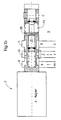
- FIG. 1 illustrates in a simplified representation using a Section of a valve device, the structure and functionality of a proportional directional valve 1 designed according to the invention a preferred embodiment electromagnetically controlled.
- An electromagnet 2 is provided for this purpose.
- the proportional directional valve 1 comprises a valve body 3, which comprises a central bore 4, in which a valve piston 5 is arranged movable in the axial direction.
- the central bore 4 are a variety of connections, at least however two, assigned. These are here in the form of connecting channels 6, 7 and 8, which extends from the outer circumference of the valve piston 5 preferably extend in the radial direction to the central bore 4.
- the connecting channel 6 acts as an inlet channel and Connection channel 7 as a drain channel.
- the connecting channels 6, 7 and 8 open into the central bore 4, which additional in the area of the channels Chambers, here 9, 10 and 11, having the central bore 4th connected, extend circumferentially and a larger one Have diameter D as the central bore 4.
- Valve housing 3 incorporated chambers 9, 10 and 11 form with the central bore 4, the control edges of the valve housing 3.
- the valve piston 5 has its axial length l different dimensions in the radial direction.
- two areas of smaller diameter d here with 12 and 13 designated, provided.
- the change between larger and larger areas smaller diameter d leads to the formation of the control edges 14, 15 and 16 on the valve piston 5.
- the control edges 14, 15 and 16 of the valve piston 5 and the control edges of the valve housing 3 have a special influence on the accuracy of the control processes. These affect the throttling the passage cross-sections and thus the speed of the work equipment or that of the valve device in the form of a proportional directional valve 1 subordinate consumers.
- the chambers 9, 10 and 11 form with the central bore 4 and the outer contour of the valve piston 5th variable pressure rooms. By shaping the individual accordingly Control edges have different flow characteristics.
- connection channel 6 serves the connection between the pressure chamber formed by the chamber 9 and the central bore 4 at least indirectly with a pressure medium supply source.
- the Connection channel 7 is used to connect the chamber 10 and the central bore 4 formed pressure chamber with one here in detail consumers not shown.
- the valve piston 5 has an interior 20, which is in the axial Direction in the direction of the valve piston 5 up to its end face 22 extends.
- This interior 20 is a movable in the axial direction Valve pin 21 arranged.
- the valve pin 21 can be different Take positions, especially this can be completely in the valve piston 5 are integrated or protrude from the valve piston 5, i.e. he extends in the axial direction over the end face 22 of the valve piston 5. So that the valve pin 21 does not come out of the interior 20 of the valve piston 5 slips out, this is in the area of its from the end face 22 of the Valve piston 5 opposite and pioneering face 23 with with a head start.
- valve pin 21 can either be a separate, the component assigned to the valve pin 21, for example in Form of a push-on, press or screwable element, preferably in Shape of a ring or the valve pin 21 can be designed such that this is designed as a one-piece component with a corresponding projection. There is at least one projection extending in the circumferential direction provided or a variety of at certain intervals in Projections arranged circumferentially.
- the interior 20 is different in two areas Diameter divided - a first area of larger diameter, here designated 24, and a second area of smaller diameter, here designated with 26.
- the area of smaller diameter 26 serves the purpose Picking up and guiding the valve pin 21.
- Diameter 25 is an energy storage unit 27 in the form of a compression spring arranged.
- an axially movable stop 28 is provided which the end face or at least part of the end face 30 of the Valve pin 21 attacks, the stop 28 on a Energy storage unit 31, supported here by a compression spring device.
- the present embodiment has two limit positions.
- the first Limit position is shown in Figure 1a.
- the connecting channel 7 the drain channel, at least indirectly connectable consumers relieved and the pressure supply via the Connection channel 6 blocked as a feed channel. This is caused by the fact that the control edges 14 to 16 the pressure chamber, which from the chamber 9 and the central bore 4 is formed, not with the corresponding Pressure chamber, which can be coupled to the consumer, connects.
- the Drain channel, i.e. the connecting line 7 to the consumer is blocked.
- FIG. 1b shows the proportional directional control valve 1 according to the invention in a switch position in which it works as a so-called proportional valve.
- the actuating device comprising an electromagnet 2 comprises at least one conductor, for example in the form of a coil, which is assigned to the electromagnet 2 and through which a current with the current intensity l flows.
- This current value I corresponds to a setpoint to be set for a desired pressure value to be applied to the consumer and to be set.
- the specification of the desired pressure value to be set at the consumer which is also referred to as signal pressure W pASoll , can be done by simple calculation or simple assignment using characteristic curves or tables stored in a storage unit. The possibility described below is not shown in the figure and is only one of many.
- the pressure setting or pressure control via the valve device 1 takes place, for example, in a first control circuit, not shown here.
- the input variables of such a control circuit are a desired signal pressure W PASOll which is set at the outlet, ie in the discharge line, and an actual value of the signal pressure in the output line P A which is continuously determined .
- the valve device 1 acts as an actuator for setting this signal pressure.
- the manipulated variable for influencing this actuator in the present case is the magnitude of the magnetic force F magnet influencing the position of the valve piston 5.
- the magnetic force F magnet corresponds to the actuating force required for the displacement of the valve piston 5 of the valve device 1 to release the individual flow cross sections between the connecting channels 6, 7 and 8.
- the setting of the magnetic force F magnet takes place via a further control loop, which is subordinate to the pressure control loop.
- the input variable of this second control circuit is a reference variable for the magnetic force F magnet target formed by the pressure regulator .
- the valve piston is displaced in the axial direction relative to the valve pin 21, the pressure spaces which are formed by the chamber 9 and the central bore 4 or the chamber 10 and the central bore 4 being connected to one another and
- This connection of the pressure chambers enables a connection between the inlet 6 and the connecting channel 7 coupled to the consumer.
- a certain pressure P lst is established in the connection channel 7.
- This pressure propagates through a connecting bore 36, which extends from the circumference 35 of the valve piston 21 in the radial direction in the direction of the interior 20, into the interior 20. This pressure acts in the interior 20 on the surface of the valve pin 21 formed by the end face 23.
- the actuating force in the form of the magnetic force F magnet always corresponds to the force applied by the energy storage unit 25 plus the pressure force F pressure which results from the consumer pressure P actual and the area A of the valve pin in the region of the end face 23.
- the valve pin 21 is supported on the prestressed energy storage unit 31 in the form of a spring unit designed as a compression spring.
- the bias of the spring unit corresponds to the force of the valve pin 21 at the maximum desired proportional pressure, so that there is no change in the spring unit in the entire proportional range.
- valve pin 21 presses 21 the spring unit 31, in particular the spring assembly, until it comes into contact with its shoulder S or the stop in the region of its end in the valve piston 5.
- the pressure in the consumer or the connecting line which is coupled to the connecting channel 7 and the consumer, can no longer affect the valve device 1.
- the position of the valve piston 5 is now determined solely on the basis of the external forces of the magnet, in particular the electromagnet 2 and the energy storage unit 31, in particular the spring unit, as in a directional control valve.
- valve piston 5 now goes with a further slight increase in the magnetic force F magnet in the axial direction up to the stop 28 and releases the unthrottled path of the equipment, in particular the oil, to the consumer.
- valve pin 21 which is dependent on the pressure in the Connecting line 7 is applied, the actuating force on the Valve piston 5 always assigned a counterforce in the proportional range, which causes 5 lower actuating forces to be effective on the valve piston have to be to allow a shift in the axial direction as in a solution without a valve pin with direct attack on the actuating force the valve piston.
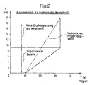
- FIG. 2 schematically illustrates the characteristic diagram of a proportional directional control valve according to the invention in a diagram which shows the dependence of the outlet pressure or the pressure provided for the consumer in channel 7 on the magnetic force F magnet .
- the magnetic force F magnet in the X direction and the output pressure P actual in the Y direction are plotted in the coordinate system.
- the characteristic curve of a conventional proportional valve is drawn with l. It can be seen from this that the pressure P actual changes linearly as a function of the magnetic force F magnet .
- the solution according to the invention makes it possible, as also shown in the characteristic curve II, to make the proportional range wider, ie to keep the increase in the characteristic curve smaller, the so-called travel range following the proportional range, in that there is no pressure limitation.
- This broadening of the proportional range over a larger magnetic force range F magnet makes it possible to fine tune the pressure to be set on the consumer in accordance with the applied magnetic force F magnet .
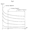
- FIG. 3 illustrates the characteristic curves for the using a diagram required magnetic force of the actuator according to Further development of the basic idea of the invention, the Actuating force is applied electro-magnetically.
- the actuator includes at least one electromagnet with a coil and one Magnetic armature, the armature under the action of the from the coil generated magnetic field is movable. From the different uses of the Magnetic force characteristic in the individual functional states "proportional valve” and “directional valve” results in the possibility of energizing the solenoid in the "directional valve” state.
- the reduction of the current supply Magnetic coil is particularly advantageous because the second part of the Overall working area, the function as a directional control valve, usually the has the largest secondary share and for the heating and durability of the coil as well as the most important for the control hardware.
- the travel range of the valve piston is in first part of the total work area, the state "proportional valve” approx. 80% or more and in the second part of the work area, the state “directional valve” approximately 20% or less of the total range. Minor deviations of these values are conceivable.
- the control position of the Valve piston usually in the middle of the path area of the valve piston.
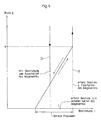
- the pressure curve must be independent of the previous position of the spool. This means that the pressure curve from below to the desired value without Pressure increases during the fill-control transition.
- FIG. 4 illustrates the course of the pressure characteristic curve over the current supply for the functions "proportional valve” and "directional valve".
- l the Range of the required current supply to the magnetic coil for safe holding of the directional control valve
- II the current required to switch on the Directional control valves
- valve device goes from the stop to the Tax position or remains in the same. It is then possible to use to set descending pressures.
- the valve is brought safely into the directional control valve state by briefly applying more current.
- the solenoid coil goes to zero position, the pressure on the valve switches off.
- the current can then be reduced to a low holding current in the zero position due to the increased magnetic forces.
Abstract
Description
Die Erfindung betrifft eine Ventileinrichtung, insbesondere eine Kombination der Funktionen eines Proportional- und eines Wegeventiles, im einzelnen mit den Merkmalen aus dem Oberbegriff des Anspruchs 1.The invention relates to a valve device, in particular a combination the functions of a proportional and a directional valve, in detail with the features from the preamble of claim 1.
Proportionalventile, auch Stetigventile genannt, sowie Wegeventile sind in einer Vielzahl von Ausführungen und für unterschiedliche Einsatzzwecke bekannt. Bei Wegeventilen handelt es sich dabei um Richtungsventile, deren Ventilkolben, welche auch als Steuerkolben bezeichnet werden, in verschiedene festgelegte Schaltstellungen gebracht werden können, wodurch unterschiedliche Verbindungen, d.h. Wege, der angeschlossenen Leitungen zur Betriebsmittelführung hergestellt werden können. Damit wird eine Änderung der Durchflußrichtung eines Volumenstromes bewirkt. Diese Ventile werden durch die Nennweite, den Nenndruck und die möglichen Wegevarianten gekennzeichnet. Die Hauptbaugruppe eines Wegeventils bildet dabei die Steuereinheit. Diese enthält in einem Ventil- bzw. Steuergehäuse den Ventilkolben, der die Richtungsänderungen des Volumenstroms bewirkt. Zur Betätigung des Ventilkolbens ist diesem an wenigstens einer der beiden Stirnseiten eine Stelleinrichtung zum Aufbringen der Betätigungskraft zugeordnet. Eine häufig eingesetzte Variante ist dabei das sogenannte Schieberventil, wobei der Ventilschluß durch Überdeckung, hervorgerufen durch das Auf- oder Ineinandergleiten der einzelnen Ventilteile, insbesondere des Ventilkolbens im Ventilgehäuse, hervorgerufen wird. Je nach Bau- und Bewegungsart der Ventilkolben werden diese Ventile in Drehschieberventile, Längsschieberventile und Längsdrehschieberventile eingeteilt. Eine entsprechende Klassifizierung der Steuer- bzw. Ventileinheiten erfolgt immer nach der Anzahl der Anschlüsse, d.h. der möglichen Leitungen, und nach der Anzahl der möglichen Schaltstellungen. Proportional valves, also called continuous valves, as well as directional valves are in a variety of designs and for different purposes known. Directional valves are directional valves whose Valve pistons, which are also referred to as control pistons, in different fixed switching positions can be brought, whereby different connections, i.e. Ways, the connected lines can be manufactured for equipment management. So that becomes a Changing the flow direction of a volume flow causes. These valves are determined by the nominal size, the nominal pressure and the possible Path variants marked. The main assembly of a directional valve forms the control unit. This contains in a valve or control housing the valve piston that changes the direction of the volume flow. To actuate the valve piston, this is on at least one of the two An actuating device for applying the actuating force on the end faces assigned. A frequently used variant is the so-called Gate valve, the valve closure caused by overlap by sliding the individual valve parts on or into one another, in particular of the valve piston in the valve housing. Depending on the construction and Movement type of the valve piston, these valves are in rotary slide valves, Longitudinal slide valves and longitudinal rotary slide valves divided. A The control or valve units are always classified accordingly according to the number of connections, i.e. of the possible lines, and after the Number of possible switch positions.
Besonderen Einfluß auf die Genauigkeit der Schaltvorgänge haben die Steuerkanten des Ventilkolbens und die des Ventilgehäuses. Sie beeinflussen die Drosselung des Durchgangsquerschnittes und damit die Geschwindigkeit des Verbrauchers, in der Regel ein Arbeitsgerät. Durch entsprechende Formgebungen dieser Steuerkanten lassen sich durch Relativbewegung des Ventilkolbens gegenüber dem Ventilgehäuse unterschiedliche Durchflußcharakteristiken erzielen. Wegeventile weisen dabei eine bestimmte Anzahl von Schaltstellungen auf.The have a special influence on the accuracy of the switching processes Control edges of the valve piston and that of the valve housing. Affect you the throttling of the passage cross-section and thus the speed of the consumer, usually an implement. By appropriate Shapes of these control edges can be achieved by moving the Valve piston different from the valve housing Achieve flow characteristics. Directional valves have a specific one Number of switch positions on.
Als Proportionalwegeventil werden stetig verstellbare, vorzugsweise elektrisch
stetig verstellbare Wegeventile bezeichnet, bei denen die Axialbewegung des
Ventilkolbens direkt durch Lage geregelte oder durch Kraft gesteuerte,
druckdichte Stelleinrichtungen proportional einem Sollwert erfolgt. Bei
elektrisch stetig verstellbaren Wegeventilen sind die Stelleinrichtungen in Form
von Steuermagneten ausgeführt, welche eine Axialbewegung des
Ventilkolbens proportional zu einem elektrischen Sollwert ermöglichen. Der
Ventilkolben kann in dem Ventilgehäuse stufenlos jede Stellung zwischen den
zwei Endlagen beliebig lange einnehmen. Dies bringt besondere Vorteile bei
der Steuerung und Regelung der Geschwindigkeit von hydraulischen
Verbrauchern. Derartige Ventile sind beispielsweise
RD 29 586/09.89
RD 29 175/03.93 und
RE 29 586 / 09.89
RE 29 175 / 03.93 and
Die derartig gestalteten Proportionalventile haben den Nachteil, daß die Betätigungskraft, welche beispielsweise elektromagnetisch, hydraulisch, mechanisch oder anderweitig aufgebracht werden kann, so gewählt werden muß, daß der maximal auftretende gewünschte Druck im dem Ventil nachgeordneten Verbraucher dauerhaft gehalten werden kann. Die Größe der Wirkfläche des Druckes bestimmt sich dabei aus dieser Forderung. Dies hat jedoch zur Folge, daß kleinere Drücke mit dementsprechend kleineren Betätigungskräften gesteuert werden müssen. Bei gewünschten kleineren Drücken müssen somit bei der Steuerung größere Druckstreuungen in Kauf genommen werden. Eine Vergrößerung des Bereiches der aufbringbaren Kraft hat in der Regel eine Vergrößerung der Stelleinrichtungen zur Folge, beispielsweise hat bei einer Ausführung einer Stelleinrichtung in Form eines Elektromagneten eine grundsätzliche Erhöhung der aufzubringenden Magnetkraft eine Vergrößerung der Magnetspule zur Folge, was jedoch einen erhöhten Platzbedarf bedingt. Des weiteren sind die Kosten größerer elektrischer Leiter höher und der Stromverbrauch nimmt zu. Im allgemeinen sind hinsichtlich des Anwendungfalles auch Grenzen für die Größe der Ventileinrichtung und der Stelleinrichtung gesetzt, so daß eine genaue Einstellung des Druckes am Verbraucher nicht immer'zu realisieren ist.The proportional valves designed in this way have the disadvantage that the Actuating force, which is electromagnetic, hydraulic, can be applied mechanically or otherwise, so be selected must be the maximum pressure that occurs in the valve downstream consumers can be kept permanently. The size of the The effective area of the pressure is determined from this requirement. this has however, the consequence is that smaller pressures with correspondingly smaller ones Operating forces must be controlled. If you want smaller ones Pressures therefore have to purchase larger pressure variations in the control be taken. An increase in the range of force that can be applied usually results in an enlargement of the adjusting devices, for example, has an actuating device in the form of a Electromagnets a fundamental increase in the amount to be applied Magnetic force results in an enlargement of the solenoid coil, which however increased space requirements. Furthermore, the cost is greater electrical conductor higher and the power consumption increases. In general are also limits for the size of the Valve device and the actuator set so that an accurate Adjustment of the pressure at the consumer is not always possible.
Der Erfindung liegt daher die Aufgabe zugrunde, eine Ventileinrichtung der eingangs genannten Art derart weiterzuentwickeln, daß die genannten Nachteile vermieden werden. Insbesondere sollen die Druckstreuungen bei möglichst geringen einzustellenden Drücken vermieden werden. Die Ventileinrichtung soll des weiteren für Einsatzfälle, an welche Anforderungen beispielsweise wie in einem Schaftgetriebe gestellt werden, bei welchen relativ geringe Drücke in einem Schaltelement möglichst genau gesteuert werden sollen, andererseits aber durch hohe Momente im Wandlerbetrieb eine hohe Übertragungsfähigkeit der Schaltelemente notwendig ist, geeignet sein. Die Ventileinrichtung soll dabei wenigstens in einem ersten Druckbereich (dem Proportionalbereich), welcher auch den Gesamtarbeitsbereich entsprechen kann, beispielsweise einer Größenordnung von 1 bis 5 bar, möglichst genau, d.h. unter Ausnutzung der maximal zulässigen Betätigungskraft, mit möglichst großen Betätigungskräften proportional einer elektrischen Stromstärke gesteuert werden können. Zusätzlich sollte das Ventil in einem zweiten höheren Druckbereich, beispielsweise von 6 bis 20 bar, dann als normales Wegeventil arbeiten, d.h unabhängig vom vorhandenen Druckniveau im Verbraucher immer den vollen Druck übertragen. Die Ventileinrichtung soll möglichst exakt reproduzierbare Schaltvorgänge mit möglichst geringen Einflüssen von hydraulischen Klemmkräften und mechanischer Reibung ermöglichen können. Der konstruktive Aufwand und die Kosten sind dabei gering zu halten.The invention is therefore based on the object of a valve device to develop the type mentioned at the outset such that the aforementioned Disadvantages are avoided. In particular, the pressure scatter should the lowest possible pressures to be set are avoided. The valve device is also intended for applications to which Requirements, for example, as in a shaft gearbox, at which relatively low pressures in a switching element as precisely as possible should be controlled, but on the other hand by high moments in the Converter operation a high transmission capacity of the switching elements is necessary to be suitable. The valve device should at least in a first pressure range (the proportional range), which also the Total work area can correspond, for example, an order of magnitude from 1 to 5 bar, as precisely as possible, i.e. taking advantage of the maximum permissible actuation force, with the greatest possible actuation forces can be controlled proportionally to an electric current. In addition, the valve should be in a second higher pressure range, for example from 6 to 20 bar, then work as a normal directional valve, i.e. regardless of the existing pressure level in the consumer, always the full one Transfer pressure. The valve device should be reproducible as precisely as possible Switching operations with the least possible influence of hydraulic Can enable clamping forces and mechanical friction. The design effort and the costs are to be kept low.
Die erfindungsgemäße Lösung ist durch die Merkmale des Anspruchs 1 gekennzeichnet. Vorteilhafte Ausgestaltungen sind in den Unteransprüchen beschrieben.The solution according to the invention is characterized by the features of claim 1 characterized. Advantageous configurations are in the subclaims described.
Die Ventileinrichtung umfaßt neben einem Ventilgehäuse mit wenigstens einem Zulaufkanal und einem Ablaufkanal, einen, im Ventilgehäuse axial bewegbaren und Steuerkanten aufweisenden Ventilkolben zum Freigeben und Absperren der Verbindung der Querschnitte von Zulauf- und Ablaufkanal sowie eine Stelleinrichtung zur Beaufschlagung des Ventilkolbens mit einer Betätigungskraft. Erfindungsgemäß sind Mittel zur Erzeugung einer der Betätigungskraft über wenigstens einen Teil des Gesamtarbeitsbereiches der Ventileinrichtung in Abhängigkeit zum Druck im Ablaufkanal entgegengerichtete Kraft vorgesehen. In einem Druckbereich, welcher einen ersten Teil eines Gesamtarbeitsbereiches der Ventileinrichtung bestimmt, wobei dieser erste Teil auch dem Gesamtarbeitsbereich entsprechen kann, wird somit der mögliche Betätigungskraftbereich gegenüber dem Druckbereich am Verbraucher vergrößert, so daß eine feinfühligere Abstimmung zwischen dem einzustellenden Druck am Verbraucher und der Betätigungskraft möglich wird, d.h. einem bestimmten Druckbereich am Verbraucher bzw. im Ablaufkanal ist ein größerer Betätigungskraftbereich gegenüber einem konventionell ausgeführten Proportionalventil zuordenbar. Dies wird nach Verbringen des Ventilkolbens in eine Steuerposition durch die Schaffung eines Gleichgewichtes zwischen der Betätigungskraft und einer Druckkraft, welche in Abhängigkeit des Druckes im Verbraucher auf eine bestimmte Fläche wirkt, die der Betätigungskraft entgegengesetzt gerichtet ist, erzielt.In addition to a valve housing, the valve device comprises at least an inlet channel and an outlet channel, one, axially in the valve housing movable and control edges having valve piston for releasing and shutting off the connection of the cross sections of the inlet and outlet channels and an actuating device for loading the valve piston with a Operating force. According to the invention, means for generating one of the Actuating force over at least part of the total working range of the Valve device depending on the pressure in the drain channel opposing force provided. In a printing area, which one determines the first part of an overall working range of the valve device, this first part can also correspond to the overall work area, is the possible operating force range compared to Pressure range on the consumer increased, so that a more sensitive Coordination between the pressure to be set on the consumer and the Actuating force becomes possible, i.e. a certain pressure range on Consumer or in the drain channel is a larger actuation force range assignable compared to a conventional proportional valve. This is achieved by moving the valve piston into a control position Creating a balance between the operating force and one Compressive force, which depends on the pressure in the consumer on a certain surface acts that is opposite to the actuating force, achieved.
Die Mittel umfassen dazu vorzugsweise einen, im Ventilkolben angeordneten und sich bis zu der von der Stelleinrichtung abgewandten Stirnseite erstreckenden Innenraum, einen im Innenraum angeordneten Ventilstift, wobei Ventilstift und Ventilkolben relativ gegeneinander bewegbar sind, einen, dem Ventilstift zugeordneten Anschlag, an welchem sich der Ventilstift abstützt, sowie einen Verbindungkanal zwischen dem Innenraum des Ventilkolbens und dem äußeren Umfang des Ventilkolbens, wobei die Mündung des Verbindungskanales am äußeren Umfang des Ventilkolbens derart angeordnet ist, daß dieser im genannten Teil des Gesamtarbeitsbereiches, dem Proportionalbereich mit dem Ablaufkanal korrespondiert.For this purpose, the means preferably comprise one arranged in the valve piston and up to the end facing away from the actuating device extending interior, a valve pin arranged in the interior, wherein Valve pin and valve piston are relatively movable against each other, one that Stop assigned to the valve pin, on which the valve pin is supported, and a connection channel between the interior of the valve piston and the outer periphery of the valve piston, the mouth of the Connection channel arranged on the outer circumference of the valve piston in this way is that this in the part of the total work area, the Proportional area corresponds to the drain channel.
Diese Ausführung ermöglicht es, das Verhältnis von Betätigungskräften zu Reibungskräften möglichst groß zu wählen. Die Reibungskräfte bestimmen sich hauptsächlich aus den Druckdifferenzen am Ventil, der Betriebsmittelverschmutzung, dem Ventildurchmesser oder sonstigen konstruktiven Merkmalen. Die Betätigungskräfte finden ihre Begrenzung hauptsächlich in der Größe der Stelleinheiten, insbesondere bei einem elektromagnetischen Antrieb in der Größe des Elektromagneten. Auch für geringe Bereiche der aufzubringenden Betätigungskräfte können geringe Druckwerte am Verbraucher bzw. dem mit dem Verbraucher gekoppelten Ablaufkanal eingestellt werden.This design enables the ratio of operating forces to To choose friction forces as large as possible. Determine the frictional forces mainly from the pressure differences across the valve, the Equipment contamination, the valve diameter or other constructive features. The operating forces are limited mainly in the size of the actuators, especially one electromagnetic drive in the size of the electromagnet. Also for small ranges of the actuation forces to be applied can be small Pressure values at the consumer or that coupled to the consumer Drain channel can be set.
Das erfindungsgemäß gestaltete Ventil wird vorzugsweise als kombinierte Proportional-Wegeventileinrichtung ausgeführt. Zur zusätzlichen Realisierung der Wegefunktion umfaßt die Ventileinrichtung des weiteren eine Einrichtung, welche die Größe der der Betätigungskraft entgegengerichteten Kraft begrenzt und kompensiert. Diese Einrichtung ist in Form einer Energiespeichereinheit ausgeführt, welche dem Anschlag für den Ventilstift zugeordnet ist und dessen Abstützkraft für den Ventilstift hinsichtlich der Größe beschränkt. Überschreitet die Druckkraft, welche aus dem Druck in der Ablaufleitung und der Stiftfläche bestimmt wird, die durch die Energiespeichereinheit aufbringbare Gegenkraft zur Abstützung des Ventilstiftes, fungiert der Anschlag nicht mehr als fester Anschlag sondern wird unter Krafteinwirkung durch den Ventilstift verschoben. Diese Verschiebung wird durch einen weiteren Anschlag zwischen Ventilstift und Ventilkolben begrenzt. Nach Erzielen der Anschlagsposition des Ventilstiftes gegenüberdem Ventilkolben, d.h. der Ventilstift ist nicht mehr gegenüber dem Ventilkolben in Richtung der Druckkraft verschiebbar, wird der Ventilkolben dann nur noch entsprechend der aufgebrachten Betätigungskraft verschoben.The valve designed according to the invention is preferably a combined one Proportional directional valve device implemented. For additional realization the directional function, the valve device further comprises a device, which limits the magnitude of the force opposing the actuating force and compensated. This device is in the form of an energy storage unit executed, which is assigned to the stop for the valve pin and its support force for the valve pin is limited in size. Exceeds the pressure force resulting from the pressure in the drain line and the pin area is determined by the energy storage unit counterforce that can be applied to support the valve pin acts as the Stop no longer as a fixed stop but becomes under the action of force shifted by the valve pin. This shift is caused by a limited further stop between valve pin and valve piston. To Achieving the stop position of the valve pin in relation to the valve piston, i.e. the valve pin is no longer opposite the valve piston in the direction of the The valve piston is then only correspondingly displaceable the applied operating force shifted.
Erfindungsgemäß wird somit bei der Ventileinrichtung, wenigstens ein erster unterer Druckbereich am Verbraucher, welcher einen ersten Teil des Gesamtarbeitsbereiches der Ventileinrichtung bestimmt, mit annähernd maximal möglichen Betätigungskräften gesteuert, während in einem oberen Druckbereich, welcher einen weiteren zweiten Teil des Gesamtarbeitsbereiches der Ventileinrichtung bestimmt, das Ventil als reines Wegeventil fungiert. Dies bedeutet für den zweiten Teil des Gesamtarbeitsbereiches, daß der im Ablaufkanal, welcher wenigstens mittelbar mit dem Verbraucher gekoppelt ist, herrschende Druck keinerlei Einfluß mehr auf die Funktion der Ventileinrichtung ausübt. Dadurch können trotz kleiner Stellgrößen präzisere Steuervorgänge im ersten Teil des Gesamtarbeitsbereiches der Ventileinrichtung, d.h. dem unteren Druckbereich ermöglicht werden. Das Umschalten der Ventileinrichtung von der Proportionalfunktion auf die Wegefunktion geschieht automatisch als Funktion des Druckes im Verbraucher. Durch entsprechende geometrische und kraftmäßige Auslegung der Ventileinrichtung kann der Umschaltpunkt festgelegt werden. According to the invention, at least one first valve device lower pressure range at the consumer, which is a first part of the Total working range of the valve device determined, with approximately maximum possible actuation forces controlled while in an upper Print area, which is another second part of the Overall working range of the valve device determines the valve as pure Directional control valve functions. This means for the second part of the Total work area that in the drainage channel, which at least is indirectly linked to the consumer, there is no pressure Influence more on the function of the valve device. This allows Despite small manipulated variables, more precise control processes in the first part of the Total working range of the valve device, i.e. the lower pressure range be made possible. Switching the valve device from the Proportional function on the way function happens automatically as a function of consumer pressure. By appropriate geometric and The switchover point can be designed by force of the valve device be determined.
Vorrichtungsmäßig weist dazu die Ventileinrichtung wenigstens ein Ventilgehäuse auf, welches eine zentrale Bohrung umfaßt, in der ein Ventilkolben in axialer Richtung bewegbar ist. Die zentrale Bohrung bildet mit dieser zugeordnete Kammer sogenannte Druckräume, welche entsprechend der Stellung des Ventilkolbens in der zentralen Bohrung eine Verbindung zwischen einer Zulaufleitung und einer Ablaufleitung, vorzugsweise der Ablaufleitung, welche mit einem Verbraucher gekoppelt ist, ermöglicht. Der Ventilkolben weist des weiteren einen Innenraum auf, in welchem ein sogenannter Ventilstift axial bewegbar angeordnet ist. Dem Ventilstift ist in Bewegungsrichtung ein Anschlag zugeordnet, welcher an einer Energiespeichereinheit abgestützt wird. Der Ventilstift bzw. dessen vom Anschlag weggewandte Stirnseite, die in den Innenraum des Ventilkolbens hineinragt, ist über einen Verbindungskanal, vorzugsweise in Form einer Verbindungsbohrung, vom Innenraum des Ventilkolbens bis zum äußeren Umfang des Ventilkolbens, der sich im Proportionalarbeitsbereich im Bereich des Ablaufes befindet, mit dem Druck in der Ablaufleitung, d.h. der Verbindungsleitung zum Verbraucher, beaufschlagt. Das Ventil ist derart konzipiert, daß in einer ersten Endstellung die Verbindung zwischen dem Zulauf und dem Ablauf, d.h. der Verbindungsleitung zum Verbraucher, gesperrt ist.In terms of the device, the valve device has at least one Valve housing, which comprises a central bore in the Valve piston is movable in the axial direction. The central hole forms with this associated chamber so-called pressure chambers, which accordingly the position of the valve piston in the central bore a connection between an inlet line and an outlet line, preferably the Drain line, which is coupled to a consumer, enables. The Valve piston also has an interior in which a so-called valve pin is axially movable. The valve pin is in Direction of movement assigned a stop, which on a Energy storage unit is supported. The valve pin or its from Stop facing away from the inside of the valve piston protrudes through a connecting channel, preferably in the form of a Connection hole, from the interior of the valve piston to the outside Scope of the valve piston, which is in the proportional work area of the drain, with the pressure in the drain line, i.e. the Connection line to the consumer, acted upon. The valve is like this designed that in a first end position the connection between the Inlet and outlet, i.e. the connecting line to the consumer, Is blocked.
Eine Verstellbarkeit des Ventilkolbens im Ventilgehäuse erfolgt mittels einer Stelleinrichtung. Diese Stelleinrichtung ist vorzugsweise in Form einer elektromagnetischen Stelleinrichtung, d.h. eines Elektromagneten, ausgeführt. Andere Möglichkeiten sind ebenfalls denkbar, beispielsweise eine elektrohydraulische oder eine mechanische Verstelleinrichtung. Bei gewünschter stufenloser Verstellung wird von seiten der Stelleinrichtung der Ventilkolben mit einer Betätigungskraft FBetätigung beaufschlagt. Dabei wird eine Verbindung zwischen den Druckräumen, die von der mit der zentralen Bohrung verbundenen Kammer und dem Einlauf sowie der zentralen Bohrung und einer Kammer am Ablauf gebildet werden, hergestellt. Das Betriebsmittel kann somit vom Zulauf zum Verbraucher abfließen. Gleichzeitig stellt sich über die Verbindungsbohrung zwischen Innenraum und äußerem Umfang des Ventilkolbens bei Position im Bereich des Ablaufes ein Druck ein, der auf die Stirnfläche des Ventilstiftes wirkt und am Anschlag im Ventilgehäuse abgestützt wird. Dabei wird ein Gleichgewichtszustand hergestellt, das bedeutet die Betätigungskraft entspricht der Druckkraft, welche sich aus Verbraucherdruck auf die Ventilstiftfläche ergibt. Bei Vorsehung einer weiteren Energiespeichereinheit zwischen Ventilkolben und Ventilstift im Innenraum des Ventilkolbens summiert sich die dadurch aufgebrachte Kraft mit der Druckkraft.The valve piston can be adjusted in the valve housing by means of an adjusting device. This actuating device is preferably designed in the form of an electromagnetic actuating device, ie an electromagnet. Other possibilities are also conceivable, for example an electro-hydraulic or a mechanical adjustment device. In the case of the desired continuous adjustment, an actuating force F actuation is applied to the valve piston on the part of the actuating device . A connection is established between the pressure chambers formed by the chamber connected to the central bore and the inlet and the central bore and a chamber at the outlet. The equipment can therefore flow from the inlet to the consumer. At the same time, a pressure is created via the connecting bore between the interior and the outer circumference of the valve piston when in position in the area of the drain, which acts on the end face of the valve pin and is supported on the stop in the valve housing. This creates an equilibrium state, which means that the actuation force corresponds to the pressure force which results from consumer pressure on the valve pin surface. If a further energy storage unit is provided between the valve piston and the valve pin in the interior of the valve piston, the force thereby applied adds up to the pressure force.
Der Ventilstift stützt sich an der dem Anschlag zugeordneten Energiespeichereinheit ab. Die von der Energiespeichereinheit aufgebrachte Kraft entspricht dabei vorzugsweise der Kraft des Ventilstiftes bei maximal gewünschtem proportionalen Druck, so daß im gesamten Proportionalbereich keine Veränderung der Kraft der Energiespeichereinheit bzw. der Lage des Anschlages stattfindet. Als unmittelbare Stellgröße für den einzustellenden maximal gewünschten proportionalen Druck ergibt sich somit die Vorspannkraft durch die Energiespeichereinheit. Erst wenn der eingesteuerte Druck im Verbraucher, d.h. im Ablauf, im Innenraum eine Kraft auf den Ventilstift erzeugt, welche höher ist als die der dem Anschlag zugeordneten Energiespeichereinheit, drückt der Ventilstift die Energiespeichereinheit zusammen, bis er mit wenigstens einem, an seinem Umfang ausgebildeten Vorsprung am Anschlag am Ventilkolben zur Anlage kommt. Sobald dieser Zustand erreicht wird, kann sich der Druck im Verbraucher nicht mehr auf das Ventil auswirken. Die Lage des Ventilkolbens bestimmt sich dann nur noch allein aufgrund der äußeren Kräfte von Stelleinheit und Energiespeichereinheit wie bei einem Wegeventil.The valve pin is supported on the stop assigned Energy storage unit. The one applied by the energy storage unit Force preferably corresponds to the force of the valve pin at maximum desired proportional pressure, so that in the entire proportional range no change in the power of the energy storage unit or the position of the Attack takes place. As an immediate manipulated variable for the one to be set maximum desired proportional pressure thus results in the Preload force by the energy storage unit. Only when the scheduled one Pressure in the consumer, i.e. in the process, in the interior a force on the Valve pin generated, which is higher than that assigned to the stop Energy storage unit, the valve pin presses the energy storage unit together until it has at least one trained on its circumference Protrusion comes to rest against the stop on the valve piston. Once this Condition is reached, the pressure in the consumer can no longer affect that Impact valve. The position of the valve piston is then only determined solely due to the external forces of the actuator and energy storage unit like a directional valve.
Für den Einsatz einer erfindungsgemäßen Ventileinrichtung mit beiden Funktionen - Proportional- und Wegefunktion - in einem Automatgegetriebe kann der Schaltdruck dabei derart ausgelegt werden, daß beispielsweise alle Schaltvorgänge im proportionalen Bereich liegen und der obere Druckbereich lediglich der Momentenübertragung dient.For the use of a valve device according to the invention with both Functions - proportional and directional function - in an automatic transmission the switching pressure can be designed such that, for example, all Switching processes are in the proportional range and the upper pressure range only serves to transfer moments.
Wesentliche Vorteile einer derartig gestalteten Ventileinrichtung bestehen darin, daß neben einer feinstufigeren Druckeinstellung eine universelle Verwendung ermöglicht werden kann, wobei mehrere Anforderungen mit optimaler Baugröße von einer Ventileinrichtung erfüllt werden können. Dies wären eine feinstufige Abstimmung von Betätigungskräften und Enddruck am Verbraucher bei geringer Größe des Druckes und die Bereitstellung und sicheres Halten eines hohen Druckes am Verbraucher.There are significant advantages of such a valve device in that, in addition to a more precise pressure setting, a universal Use can be made with multiple requirements optimal size can be met by a valve device. This would be a fine-tuning of actuation forces and final pressure on Consumers with small size of the print and the deployment and safe holding of a high pressure at the consumer.
Die Energiespeichereinheiten sind vorzugsweise in Form von Druckspeichereinheiten, beispielsweise einezelnen Druckfedern oder Federpaketen ausgeführt. Denkbar ist auch die Verwendung elastischer Membranen.The energy storage units are preferably in the form of Pressure storage units, for example individual compression springs or Spring packs executed. The use of elastic is also conceivable Membranes.
Die Ventileinrichtung kann unter Verzicht auf die Energiespeichereinheit am
Anschlag als reines Proportionalventil betrieben werden oder aber bei
Auslegung der Energiespeichereinheit derart, daß die Betätigungskraft sofort
zum Verschieben des Ventilkolbens in eine Endlage führt, was bei einer
geringen Vorspannkraft der Energiespeichereinheit ermöglicht wird, als reines
Wegeventil betrieben werden. Eine geringe Vorspannkraft der
Energiespeichereinheit ergibt einen kleinen Proportionalbereich, eine große
Vorpannkraft der Energiespeichereinheit ergibt einen großen
Proportionalbereich. Dies ermöglicht es, eine kompakte Ventilgrundbaueinheit
gemäß Anspruch 11 zu schaffen, welche durch geringfügige Modifikationen
mühelos an unterschiedliche Anforderungan angepaßt werden kann, wobei
die einzelnen Komponenten auch als Austauschkomponeten ausgeführt
werden können. The valve device can be dispensed with without the energy storage unit
Stop operated as a purely proportional valve or at
Design of the energy storage unit so that the operating force immediately
to move the valve piston into an end position, which in a
low biasing force of the energy storage unit is made possible as pure
Directional control valve operated. A low preload
Energy storage unit results in a small proportional area, a large one
Biasing force of the energy storage unit results in a large one
Proportional range. This enables a compact basic valve unit
according to
Die erfindungsgemäß gestaltete Ventileinrichtung kann jede Art von Stelleinrichtung umfassen, d.h. der Einsatz elektromagnetisch, mechanisch, hydraulisch oder anderweitig betreibbarer Stelleinrichtungen ist denkbar.The valve device designed according to the invention can be of any type Actuator include, i.e. the use of electromagnetic, mechanical, Hydraulic or otherwise operable actuators are conceivable.
Elektromagnetische Stelleinrichtungen umfassen wenigstens einen Elektromagneten mit einer Spule und einem Anker.Electromagnetic actuators include at least one Electromagnet with a coil and an armature.
Unter einem weiteren Aspekt der Erfindung ist bei elektro-magnetischer Aufbringung der Betätigungskraft vorgesehen, den einzelnen Funktionszuständen "Proportionalventil" und "Wegeventil" unterschiedliche Wegbegrenzungen des Ventilkolbens bzw. des Magnetankers zuzuordnen. Damit kann die Bestromung der Magnetspule im Zustand Wegeventil verringert werden, was sich als besonders vorteilhaft erweist, insbesodere da dieser Zustand den größten Zeitanteil beansprucht und somit für die Erwärmung und Haltbarkeit der Spule sowie die Hardware der Steuerung die größte Bedeutung besitzt. Der mögliche Hub im Proportionalbereich beträgt ungefähr ca. 80 % bezogen auf den Gesamthub. Geringfügige Abweichungen sind denkbar.In another aspect of the invention is electromagnetic Application of the actuating force provided to the individual Functional states "proportional valve" and "directional valve" different Assign travel limits of the valve piston or the magnet armature. This can energize the solenoid in the directional control valve state be reduced, which proves to be particularly advantageous, in particular there this state takes up the most time and therefore for the Heating and durability of the coil as well as the hardware of the controller is of the greatest importance. The possible stroke in the proportional range is about 80% of the total stroke. Minor deviations are conceivable.
Die erfindungsgemäße Lösung ist nachfolgend anhand von Figuren erläutert. Darin ist folgendes dargestellt:
- Fig. 1a und 1b
- verdeutlichen anhand einer Darstellung in zwei Betriebszuständen eine erfindungsgemäße Ausführung einer Ventileinrichtung;
- Fig. 2
- zeigt im Vergleich die Kennlinienen eines konventionellen Proportionalventiles und eines erfindungsgemäß gestalteten kombinierten Proportional- Wegeventiles anhand eines Diagrammes für die Abhängigkeit des einzustellenden Druckes im Verbraucher von der Größe der Magnetkraft;
- Fig. 3
- verdeutlicht in einem Diagramm den Zusammenhang zwischen Magnetkraft und Ventilkolben- bzw. Magnetspulenweg;
- Fig. 4
- verdeutlicht in einem Diagramm die erforderliche Bestromung für die Funktionen "Proportionalventil" und "Wegeventil".
- 1a and 1b
- illustrate an embodiment of a valve device according to the invention on the basis of a representation in two operating states;
- Fig. 2
- shows in comparison the characteristics of a conventional proportional valve and a combined proportional directional valve designed according to the invention using a diagram for the dependence of the pressure to be set in the consumer on the magnitude of the magnetic force;
- Fig. 3
- illustrates in a diagram the relationship between magnetic force and valve piston or solenoid travel;
- Fig. 4
- shows the required current for the functions "proportional valve" and "directional valve" in a diagram.
Die Figur 1 verdeutlicht in vereinfachter Darstellung anhand eines
Ausschnittes aus einer Ventileinrichtung den Aufbau und die Funktionsweise
eines erfindungsgemäß gestalteten Proportional-Wegeventils 1. Dieses wird in
einer bevorzugten Ausführung elektromagnetisch angesteuert. Zu diesem
Zweck ist ein Elektromagnet 2 vorgesehen. Das Proportional-Wegeventil 1
umfaßt einen Ventilkörper 3, welcher eine zentrale Bohrung 4 umfaßt, in
welcher ein Ventilkolben 5 in axialer Richtung bewegbar angeordnet ist. Der
zentralen Bohrung 4 sind eine Vielzahl von Anschlüssen, mindestens jedoch
zwei, zugeordnet. Dieses sind hier in Form von Verbindungskanälen 6, 7 und
8 dargestellt, welche sich vom äußeren Umfang des Ventilkolbens 5
vorzugsweise in radialer Richtung bis zur zentralen Bohrung 4 erstrecken.
Dabei fungiert der Verbindungskanal 6 als Zulaufkanal und der
Verbindungskanal 7 als Ablaufkanal. Die Verbindungskanäle 6, 7 und 8
münden in die zentrale Bohrung 4, welche im Bereich der Kanäle zusätzliche
Kammern, hier 9, 10 und 11, aufweist, die mit der zentralen Bohrung 4
verbunden sind, sich in Umfangsrichtung erstrecken und einen größeren
Durchmesser D als die zentrale Bohrung 4 aufweisen. Diese in das
Ventilgehäuse 3 eingearbeiteten Kammern 9, 10 und 11 bilden mit der
zentralen Bohrung 4 die Steuerkanten des Ventilgehäuses 3.Figure 1 illustrates in a simplified representation using a
Section of a valve device, the structure and functionality
of a proportional directional valve 1 designed according to the invention
a preferred embodiment electromagnetically controlled. To this
An
Der Ventilkolben 5 weist im dargestellten Fall über seine axiale Länge l
unterschiedliche Abmessungen in radialer Richtung auf. Im dargestellten Fall
sind zwei Bereiche geringeren Durchmessers d, hier mit 12 und 13
bezeichnet, vorgesehen. Der Wechsel zwischen den Bereichen größeren und
geringeren Durchmessers d führt zur Ausbildung der Steuerkanten 14, 15 und
16 am Ventilkolben 5. Die Steuerkanten 14, 15 und 16 des Ventilkolbens 5
und die Steuerkanten des Ventilgehäuses 3 haben einen besonderen Einfluß
auf die Genauigkeit der Steuervorgänge. Diese beeinflussen die Drosselung
der Durchgangsquerschnitte und damit die Geschwindigkeit der Arbeitsgeräte
bzw. der der Ventileinrichtung in Form eines Proportional-Wegeventils 1
nachgeordneten Verbraucher. Die Kammern 9, 10 und 11 bilden dabei mit der
zentralen Bohrung 4 und der äußeren Kontur des Ventilkolbens 5
veränderliche Druckräume. Durch entsprechende Formgebung der einzelnen
Steuerkanten werden unterschiedliche Durchflußcharakteristiken erzielt.In the case shown, the
Im dargestellten Fall ist eine Ventileinrichtung 1 mit drei Anschlüssen
dargestellt. Der Verbindungskanal 6 dient dabei der Verbindung zwischen
dem von der Kammer 9 und der zentralen Bohrung 4 gebildeten Druckraum
wenigstens mittelbar mit einer Druckmittelversorgungsquelle. Der
Verbindungskanal 7 dient zur Verbindung des von der Kammer 10 und der
zentralen Bohrung 4 gebildeten Druckraumes mit einem hier im einzelnen
nicht dargestellten Verbraucher.In the case shown is a valve device 1 with three connections
shown. The
Der Ventilkolben 5 weist einen Innenraum 20 auf, welcher sich in axialer
Richtung in Richtung des Ventilkolbens 5 bis zu dessen Stirnseite 22
erstreckt. In diesem Innenraum 20 ist ein in axialer Richtung bewegbarer
Ventilstift 21 angeordnet. Der Ventilstift 21 kann dabei unterschiedliche
Stellungen einnehmen, insbesondere kann dieser vollständig im Ventilkolben
5 integriert werden oder aber aus dem Ventilkolben 5 hinausragen, d.h. er
erstreckt sich in axialer Richtung über die Stimseite 22 des Ventilkolbens 5.
Damit der Ventilstift 21 nicht aus dem Innenraum 20 des Ventilkolbens 5
hinausrutscht, ist dieser im Bereich seiner von der Stirnseite 22 des
Ventilkolbens 5 gegenüberliegenden und wegweisenden Stirnseite 23 mit
einem Vorsprung versehen. Dieser Vorsprung kann entweder als separates,
dem Ventilstift 21 zugeordnetes Bauteil ausgeführt sein, beispielsweise in
Form eines Aufsteck-, Preß- oder schraubbaren Elementes, vorzugsweise in
Form eines Ringes oder der Ventilstift 21 kann derart ausgebildet werden, daß
dieser als einteiliges Bauteil mit entsprechendem Vorsprung ausgeführt wird.
Dabei ist wenigstens ein sich in Umfangsrichtung erstreckender Vorsprung
vorgesehen oder aber eine Vielzahl von in bestimmten Abständen in
Umfangsrichtung angeordneten Vorsprüngen.The
Des weiteren ist der Innenraum 20 in zwei Bereiche unterschiedlichen
Durchmessers unterteilt - einen ersten Bereich größeren Durchmessers, hier
mit 24 bezeichnet, und einen zweiten Bereich geringeren Durchmessers, hier
mit 26 bezeichnet. Der Bereich geringeren Durchmessers 26 dient dabei der
Aufnahme und Führung des Ventilstiftes 21. Im Bereich größeren
Durchmessers 25 ist eine Energiespeichereinheit 27 in Form einer Druckfeder
angeordnet.Furthermore, the interior 20 is different in two areas
Diameter divided - a first area of larger diameter, here
designated 24, and a second area of smaller diameter, here
designated with 26. The area of
Auf der der Stelleinrichtung, hier dem Elektromagneten 2, abgewandten
Stirnseite 22 des Ventilkolbens 5 ist im sich daran anschließenden Bereich der
zentralen Bohrung 4 ein axial bewegbarer Anschlag 28 vorgesehen, an
welchem die Stirnfläche oder wenigstens ein Teil der Stirnfläche 30 des
Ventilstiftes 21 angreift, wobei der Anschlag 28 sich an einer
Energiespeichereinheit 31, hier einer Druckfedereinrichtung abstützt.On the actuator, here the
Die vorliegende Ausführung weist zwei Grenzstellungen auf. Die erste
Grenzstellung ist in der Figur 1a dargestellt. In diesem, stromlosen Zustand,
ist der mit dem Verbindungskanal 7, dem Ablaufkanal, wenigstens mittelbar
koppelbare Verbraucher entlastet und die Druckzufuhr über den
Verbindungskanal 6 als Zuführkanal gesperrt. Dies wird dadurch bewirkt, daß
die Steuerkanten 14 bis 16 den Druckraum, welcher von der Kammer 9 und
der zentralen Bohrung 4 gebildet wird, nicht mit dem entsprechenden
Druckraum, welcher mit dem Verbraucher koppelbar ist, verbindet. Der
Ablaufkanal, d.h. die Verbindungsleitung 7 zum Verbraucher ist gesperrt.The present embodiment has two limit positions. The first
Limit position is shown in Figure 1a. In this de-energized state,
is that with the connecting
In der Figur 1b ist das erfindungsgemäße Proportional-Wegeventil 1 in einer
Schaltstellung dargestellt, in welcher es als sogenanntes Proportionalventil
arbeitet. Die einen Elektromagneten 2 umfassende Stelleinrichtung umfaßt
wenigstens einen Leiter, beispielsweise in Form einer Spule, der dem
Eleketromagneten 2 zugeordnet ist und welcher von einem Strom mit der
Stromstärke l durchflossen wird. Dieser Stromstärkewert l entspricht dabei
einem einzustellenden Sollwert für einen gewünschten am Verbraucher
anliegenden und einzustellenden Druckwertes. Die Vorgabe des gewünschten
einzustellenden Druckwertes am Verbraucher, der auch als Stelldruck WpASoll
bezeichnet wird, kann dabei durch einfache Berechnung oder einfache
Zuordnung über in einer Speichereinheit abgelegte Kennlinien oder Tabellen
erfolgen. Die nachfolgend beschriebene Möglichkeit ist nicht in der Figur
dargestellt und ist nur eine von vielen. Die Druckeinstellung bzw.
Druckregelung über die Ventileinrichtung 1 erfolgt dabei beispielsweise in
einem ersten, hier nicht dargestellten Regelkreis. Eingangsgrößen eines
derartigen Regelkreises sind dabei ein gewünschter, sich am Ausgang, d.h. in
der Ablaufleitung einstellender Stelldruck WPASOll sowie ein fortlaufend aktuell
ermittelter Istwert des Stelldruckes in der Ausgangsleitung PA lst. Die
Ventileinrichtung 1 fungiert dabei als Stellglied zur Einstellung dieses
Stelldruckes. Die Stellgröße zur Beeinflussung dieses Stellgliedes ist im
vorliegenden Fall die die Position des Ventilkolbens 5 beeinflussende Größe
der Magnetkraft FMagnet Die Magnetkraft FMagnet entspricht der erforderlichen
Betätigungskraft für die Verschiebung des Ventilkolbens 5 der
Ventileinrichtung 1 zur Freigabe der einzelnen Durchflußquerschnitte zwischen
den Verbindungskanälen 6, 7 und 8. Die Einstellung der Magnetkraft FMagnet
erfolgt dabei über einen weiteren Regelkreis, welcher dem Druckregelkreis
unterlagert ist. Eingangsgröße dieses zweiten Regelkreises ist eine vom
Druckregler gebildete Führungsgröße für die Magnetkraft FMagnet Soll. FIG. 1b shows the proportional directional control valve 1 according to the invention in a switch position in which it works as a so-called proportional valve. The actuating device comprising an
Entsprechend der Größe der Magnetkraft FMagnet wird der Ventilkolben in
axialer Richtung relativ zum Ventilstift 21 verschoben, wobei die Druckräume,
welche von der Kammer 9 und der zentralen Bohrung 4 bzw. der Kammer 10
und der zentralen Bohrung 4 gebildet werden, miteinander verbunden werden
und über diese Verbindung der Druckräume eine Verbindung zwischen dem
Zulauf 6 und dem mit dem Verbraucher gekoppelten Verbindungskanal 7
ermöglicht. Über die Verbindung zwischen den Druckräumen, welche von der
Kammer bzw. 10 und der zentralen Bohrung 4 gebildet werden, stellt sich im
Verbindungskanal 7 ein bestimmter Druck Plst ein. Dieser Druck pflanzt sich
über eine Verbindungsbohrung 36, die sich vom Umfang 35 des Ventilkolbens
21 in radialer Richtung in Richtung des Innenraumes 20 erstreckt, bis in den
Innenraum 20 fort. Dieser Druck beaufschlagt im Innenraum 20 die von der
Stirnseite 23 gebildete Fläche des Ventilstiftes 21. Dabei herrscht immer ein
Gleichgewichtszustand, d.h. die Betätigungskraft in Form der Magnetkraft
FMagnet entspricht immer der von der Energiespeichereinheit 25 aufgebrachten
Kraft plus der Druckkraft FDruck, welche sich aus dem Verbraucherdruck Plst
und der Fläche A des Ventilstiftes im Bereich der Stimseite 23 ergibt. Der
Ventilstift 21 stützt sich dabei an der vorgespannten Energiespeichereinheit 31
in Form einer als Druckfeder ausgeführten Federeinheit ab. Die Vorspannung
der Federeinheit entspricht dabei der Kraft des Ventilstiftes 21 bei maximal
gewünschtem proportionalem Druck, so daß im gesamten Proportionalbereich
keine Veränderung an der Federeinheit stattfindet.According to the magnitude of the magnetic force F magnet , the valve piston is displaced in the axial direction relative to the
Sobald der eingestellte Druck Plst in dem mit dem Verbindungskanal 7
wenigstens mittelbar gekoppelten Verbraucher eine Kraft auf dem Ventilstift
21, insbesondere der Fläche A an der Stimseite 23 des Ventilstiftes 21
erzeugt, welche höher ist als die Kraft der vorgespannten Federeinheit 31,
drückt der Ventilstift 21 die Federeinheit 31, insbesondere das Federpaket
zusammen, bis er mit seiner Schulter S bzw. dem Anschlag im Bereich seines
Endes im Ventilkolben 5 zum Anliegen kommt. Sobald dieser Zustand erreicht
ist, kann sich der Druck im Verbraucher bzw. der Verbindungsleitung, welche
mit dem Verbindungskanal 7 und dem Verbraucher gekoppelt ist, nicht mehr
auf die Ventileinrichtung 1 auswirken. Die Lage des Ventilkolbens 5 bestimmt
sich nunmehr allein aufgrund der äußeren Kräfte von Magnet, insbesondere
des Elektromagneten 2 und der Energiespeichereinheit 31, insbesondere der
Federeinheit wie bei einem Wegeventil.As soon as the set pressure P is generated in the consumer, which is at least indirectly coupled to the connecting channel 7, a force on the
Der Ventilkolben 5 geht nun bei weiterem geringfügigen Ansteigen der
Magnetkraft FMagnet in axialer Richtung bis zum Anschlag 28 und gibt den
ungedrosselten Weg des Betriebsmittels, insbesondere des Öls zum
Verbraucher frei.The
Durch das Vorsehen eines Ventilstiftes 21, welcher vom Druck in der
Verbindungsleitung 7 beaufschlagt wird, wird der Betätigungskraft auf den
Ventilkolben 5 im Proportionalbereich immer eine Gegenkraft zugeordnet,
welche bewirkt, daß am Ventilkolben 5 geringere Betätigungskräfte wirksam
werden müssen um eine Verschiebung in axialer Richtung zu ermöglichen als
bei einer Lösung ohne Ventilstift mit direktem Angriff der Betätigungskraft auf
den Ventilkolben.By providing a
Die Figur 2 verdeutlicht schematisch das Kennfeld eines erfindungsgemäßen
Proportional-Wegeventils in einem Diagramm, welches die Abhängigkeit des
Ausgangsdruckes bzw. des für den Verbraucher bereitgestellten Druckes im
Kanal 7 von der Magnetkraft FMagnet wiedergibt. Zu diesem Zweck ist im
Koordinatensystem die Magnetkraft FMagnet in X-Richtung und der
Ausgangsdruck Plst in Y-Richtung abgetragen. Zum Vergleich ist mit l die
Kennlinie eines herkömmlichen Proportionalventils eingezeichnet. Daraus ist
ersichtlich, daß sich der Druck Plst in Abhängigkeit der Magnetkraft FMagnet linear
ändert. Die erfindungsgemäße Lösung ermöglicht es demgegenüber, wie
auch in der Kennlinie ll dargestellt, den proportionalen Bereich breiter zu
gestalten, d.h. den Anstieg der Kennlinie geringer zu halten, wobei sich an
den proportionalen Bereich der sogenannte Wegbereich anschließt, indem
keine Druckbegrenzung erfolgt. Diese Verbreiterung des proportionalen
Bereiches über einen größeren Magnetkraftbereich FMagnet ermöglicht es, den
am Verbraucher einzustellenden Druck feiner entsprechend der aufgebrachten
Magnetkraft FMagnet abzustimmen.FIG. 2 schematically illustrates the characteristic diagram of a proportional directional control valve according to the invention in a diagram which shows the dependence of the outlet pressure or the pressure provided for the consumer in
Die Figur 3 verdeutlicht anhand eines Diagrammes die Kennlinien für die
erforderliche Magnetkraft der Betätigungseinrichtung gemäß einer
Weiterentwicklung des erfindungsgemäßen Grundgedankens, wobei die
Betätigungskraft elektro-magnetisch aufgebracht wird. Die Stelleinrichtung
umfaßt dazu wenigstens einen Elektromagneten mit einer Spule und einem
Magnetanker, wobei der Anker unter der Wirkung des von der Spule
erzeugten Magnetfeldes beweglich ist. Aus der unterschiedlichen Nutzung der
Magnetkraftkennlinie in den einzelnen Funktionszuständen "Proportionalventil"
und "Wegeventil" ergibt sich die Möglichkeit, die Bestromung der Magnetspule
im Zustand "Wegeventil" zu verringern. Die Verringerung der Bestromung der
Magnetspule ist besonders vorteilhaft, da der zweite Teil des
Gesamtarbeitsbereiches, die Funktion als Wegeventil, in der Regel den
größten Zweitanteil besitzt und für die Erwärmung und Haltbarkeit der Spule
sowie für die Hardware der Steuerung die größte Bedeutung besitzt. Dies wird
durch unterschiedliche Wegbegrenzungen erzielt, so daß, wie beispielsweise
dargestellt, im Funktionszustand "Proportionalventil" der Wegbereich 3,2 bis
0,7 und im Zustand "Wegeventil" der Anschlag bei Weg 0 genutzt wird. Mit
Weg ist dabei beispielsweise der vom Magnetanker zurückgelegte Weg bzw.
der Weg des mit diesem gekoppelten Ventilkolbens gemeint. Durch die
gezielte Überhöhung der Magnetkräfte in dieser Anschlagstellung kann die
Bestromung der Magnetspule deutlich abgesenkt werden, ohne daß für den
Betrieb als Proportionalventil Nachteile entstehen.FIG. 3 illustrates the characteristic curves for the using a diagram
required magnetic force of the actuator according to
Further development of the basic idea of the invention, the
Actuating force is applied electro-magnetically. The actuator
includes at least one electromagnet with a coil and one
Magnetic armature, the armature under the action of the from the coil
generated magnetic field is movable. From the different uses of the
Magnetic force characteristic in the individual functional states "proportional valve"
and "directional valve" results in the possibility of energizing the solenoid
in the "directional valve" state. The reduction of the current supply
Magnetic coil is particularly advantageous because the second part of the
Overall working area, the function as a directional control valve, usually the
has the largest secondary share and for the heating and durability of the coil
as well as the most important for the control hardware. this will
achieved by different path limits so that, such as
shown, in the functional state "proportional valve" the travel range 3.2 to
0.7 and in the "directional valve" state the stop at
In Figur 3 ist ersichtlich, daß im ersten Teil des Gesamtarbeitsbereiches, dem Funktionszustand Proportionalventil, ein weitestgehend konstanter Verlauf der Magnetkraft, nur abhängig von der Bestromung der Spule, realisiert wird, während im zweiten Teil, dem Funktionszustand "Wegeventil" ein kräftiger Anstieg der Magnetkräfte zu verzeichnen ist.In Figure 3 it can be seen that in the first part of the overall work area, the Functional state of proportional valve, a largely constant course of Magnetic force, only dependent on the energization of the coil, while in the second part, the functional state "directional valve" is a powerful one Magnetic forces are increasing.
Konstruktiv werden diese Begrenzungen beispielsweise dadurch gelöst, daß die Hubbegrenzung für die Funktion "Proportionalventil" durch das vorgespannte Federpaket des Ventils realisiert wird, während im Zustand Wegeventil beispielsweise ein zweiter Anschlag in der Magnetspule wirksam wird. Das Federpaket des Ventiles übt auf den Ventilstift eine zur Kraft, welche aus dem Druck im Ablaufkanal auf die Stirnfläche des Ventilstiftes gebildet wird, entgegengerichtete Kraft aus.Constructively, these limitations are solved, for example, by the fact that the stroke limitation for the "proportional valve" function by the preloaded spring assembly of the valve is realized while in the state Directional control valve effective, for example, a second stop in the solenoid becomes. The spring assembly of the valve exerts a force on the valve pin, which formed from the pressure in the drain channel on the end face of the valve pin opposing force.
Wie im Diagramm ersichtlich, beträgt der Wegebereich des Ventilkolbens im ersten Teil des Gesamtarbeitsbereiches, dem Zustand "Proportionalventil" ca. 80% oder mehr und im zweiten Teilarbeitsbereich , dem Zustand "Wegeventil" ca. 20% oder weniger des Gesamtwegebereiches. Kleinere Abweichungen von diesen Werten sind denkbar. As can be seen in the diagram, the travel range of the valve piston is in first part of the total work area, the state "proportional valve" approx. 80% or more and in the second part of the work area, the state "directional valve" approximately 20% or less of the total range. Minor deviations of these values are conceivable.
Im Funktionszustand Proportionalventil befindet sich die Steuerstellung des Ventilkolbens meist in der Mitte des Wegebereiches des Ventilkolbens. Beim Einsteuern, z.B. nach Füllvorgängen muß der Druckverlauf unabhängig von der vorangegengenen Position des Steuerschiebers sein. Dies bedeutet, daß der Druckverlauf sich von unten auf den gewünschten wert ohne Drucküberhöhungen beim Übergang Füllen-Steuern einstellt.In the proportional valve operating state, the control position of the Valve piston usually in the middle of the path area of the valve piston. At the Taxation, e.g. after filling, the pressure curve must be independent of the previous position of the spool. This means that the pressure curve from below to the desired value without Pressure increases during the fill-control transition.
Figur 4 verdeutlicht den Verlauf der Druckkennlinie über der Bestromung für die Funktionen "Proportionalventil" und "Wegeventil". Darin kennzeichnet l den Bereich der erforderlichen Bestromung der Magnetspule zum sicheren Halten des Wegeventiles, II die erforderliche Bestromung zum Einschalten des Wegeventiles und lll die Kennlinie für die kritische Bestromung zum Ausschalten des Wegeventiles.FIG. 4 illustrates the course of the pressure characteristic curve over the current supply for the functions "proportional valve" and "directional valve". In it, l marks the Range of the required current supply to the magnetic coil for safe holding of the directional control valve, II the current required to switch on the Directional control valves and the characteristic curve for the critical energization to Switch off the directional valve.
Beim Einsatz der Ventileinrichtung in Schaltgetrieben ist die Ventileinrichtung
im Funktionszustand Proportionalventil in wenigstens zwei Bereichen wirksam:
Beim gesteuerten Füllvorgang befindet sich der Ventilkolben während des Füllvorganges bereits in der Steuerstellung.When the valve device is used in manual transmissions, the valve device is effective in the functional state of proportional valve in at least two areas:
With the controlled filling process, the valve piston is already in the control position during the filling process.
Für den Synchronisiervorgang geht die Ventileinrichtung vom Anschlag in die Steuerstellung oder bleibt in der selben. Es ist dann möglich beliebige aufoder absteigende Drücke einzustellen. For the synchronization process, the valve device goes from the stop to the Tax position or remains in the same. It is then possible to use to set descending pressures.
Zum Steuern nach der Synchronisation:
Durch eine kurzzeitige stärkere Bestromung wird das Ventil sicher in den
Zustand Wegeventil gebracht. Die Magnetspule geht dabei in stellung Null,
die Druckbeeinflussung des ventiles schaltet ab. Anschließend kann die
Bestromung aufgrund der angestiegenen Magnetkräfte in der Stellung Null auf
einen geringen Haltestrom abgesenkt werden.To control after synchronization:
The valve is brought safely into the directional control valve state by briefly applying more current. The solenoid coil goes to zero position, the pressure on the valve switches off. The current can then be reduced to a low holding current in the zero position due to the increased magnetic forces.
Claims (18)
- Proportional-direction control valve device (1)characterised by the following feature:1.1 comprising a valve housing (3) with at least one feed duct (6) and one discharge duct (7);1.2 comprising a valve piston (5) which is axially movable in the valve housing (3) and has control edges (14, 15, 16) , for releasing and locking the connection of the cross-sections of the feed duct (6) and discharge duct (7) ;1.3 comprising an adjusting device for loading the valve piston (5) with an actuating force;1.4 means are provided for generating a force counter to the actuating force via at least one first part of the total operating range of the valve device (1) , as a function of the pressure in the discharge duct (7), comprising1.4.1 a cavity (20) arranged in the valve piston (5) ;1.4.2 a valve pin (21) arranged at least partly in the cavity (20), wherein the valve pin (21) and valve piston (5) are movable relative to one another in the axial direction ;1.4.3 a connecting duct (36) between the cavity (20) of the valve piston (5) and the outer periphery of the valve piston (5) , wherein the mouth of the connecting duct (36) on the outer periphery of the valve piston (5) is arranged in such a way that it communicates with the discharge duct (7) in the first part of the total operating range at least indirectly and loads the valve pin (21) with the pressure in the discharge duct (7) ;1.4.4 an energy storage device (31, F2) exerting a force on the valve pin (21) in the valve housing (3) counter to the actuating force and/or force on the valve pin (21);1.4.5 a displaceable stop (28) associated with the valve pin (21) in the valve housing (3) for limiting the axial movement in the direction of action of the force, which force can be determined by the pressure in the discharge duct end acts on the valve pin (21) which is supported on the energy storage device (31, F2);the valve pin (21) comprises at least one projection (S) on the periphery in its region arranged in the cavity (20), a stop in the valve piston (5) being associated with this projection (S) , the valve piston (5) being displaced in the axial direction in the first part of the total operating range, and both the valve pin (21) up to the stop in the valve piston (5) and the valve piston (5) being displaceable in the axial direction in a second part of the total operating range.
- Valve device (1) according to claim 1, characterised in that the means further comprise an energy storage device (F1) arranged in the cavity (20) of the valve piston (5) between the valve piston (5) and the valve pin (21).
- Valve device (1) according to either of claims 1 or 2, characterised in that the means generate a force which is directly proportional to and counter to the pressure in the discharge duct (7).
- Valve device (1) according to any one of claims 1 to 3, characterised in that the energy store units (31, F2, F1) comprise at least one compression spring unit.
- Valve device (1) according to any one of claims 1 to 3, characterised in that the energy store units (31, F2, F1) comprise resilient membranes.
- Valve device (1) according to any one of claims 1 to 4, characterised in that the valve pin (21) and the cavity (20) of the valve piston (5) have a circular cross-section.
- Valve device (1) according to any one of claims 1 to 6, characterised in that the adjusting device is designed as an electromechanical adjusting device.
- Valve device (1) according to any one of claims 1 to 6, characterised in that the adjusting device is designed as a hydraulic adjusting device.
- Valve device (1) according to any one of claims 1 to 6, characterised in that the adjusting device is designed as an electromagnetic adjusting device (2) comprising an electromagnet with an associated conductor.
- Valve device (1) according to claim 9, characterised by the following features:10.1 the electromechanically acting adjusting device (2) comprises at least one electromagnet with a coil and an armature which can be moved by the action of the magnetic field which can be generated by the coil, and is at least indirectly coupled to the valve piston (5) ;10.2 a respective travel limit - a first travel limit and a second travel limit - is at least indirectly associated with the magnetic armature for the individual partial ranges of the total operating range, the first travel limit for the first part of the total operating range being active in a range between 70 and about 80% travel and the second travel limit in a range between 70 or 80 and 100%.
- Valve device (1) according to claim 10, characterised in that the first travel limit is produced via the spring device (F1) and the second travel limit is produced via a stop associated with the magnetic armature.
- Valve device (1) according to any one of claims 1 to 11, characterised in that the bias of the energy storage device (31, F2) corresponds to the force on the control pin (21) in the case of a specific maximum proportional pressure.
- Base valve unit13.1 comprising a valve housing (3) with at least one feed duct (6) and a discharge duct (7);13.2 comprising a valve piston (5) which is axially movable in the valve housing (3) and has control edges for releasing and locking the connection of the cross-sections of the feed duct (6) and discharge duct (7);13.3 comprising an adjusting device for loading the valve piston (5) with an actuating force;13.4 comprising a cavity (20) arranged in the valve piston (5) and extending to the end face thereof remote from the adjusting device;13.5 comprising a valve pin (21) arranged at least partly in the cavity (20), wherein the valve pin (21) and valve piston (5) are movable relative to one another in the axial direction;13.6 comprising a connecting duct (36) between the cavity (20) of the valve piston (5) and the outer periphery of the valve piston (5), wherein the mouth of the connecting duct (36.) is arranged on the outer periphery of the valve piston (5) in such a way that it communicates at least indirectly with the discharge duct (7) and loads the valve pin (21) with the pressure in the discharge duct (7) ;13.7 comprising a stop (28) associated with the valve pin (21) in the valve housing (3);
characterised by the following feature:13.8 the valve pin (21) comprises at least one projection on the periphery in its region arranged in the cavity, a stop in the valve piston (5) being associated with this projection. - Base valve unit according to claim 13, characterised by the following feature:14.1 comprising an energy storage device (31, F2) associated with the stop (28) in the valve housing (3) and the valve pin (21) for at least indirect support of the valve pin (21).
- Base valve unit according to either of claims 13 or 14, characterised by the following features:15.1 in the cavity (20) of the valve piston (5) is arranged a further energy storage device for generating a further second force counter to the actuating force;15.2 the further energy storage device is arranged between the inner wall of the cavity (20) and the valve pin (21) to generate a further second force counter to the actuating force.
- Base valve unit according to any one of claims 13 to 15, characterised in that the energy storage devices are designed in the form of compression spring units.
- Base valve unit according to any one of claims 13 to 16, characterised in that the energy storage devices are designed in the form of resilient membranes.
- Base valve unit according to any one of claims 13 to 17, characterised in that the energy storage device associated with the stop is selected in such a way that in the installed position the supporting force which can be generated corresponds to the force of the valve pin at the desired maximum proportional pressure.
Applications Claiming Priority (5)
| Application Number | Priority Date | Filing Date | Title |
|---|---|---|---|
| DE29705635U | 1997-04-02 | ||
| DE29705635U DE29705635U1 (en) | 1997-04-02 | 1997-04-02 | Valve device, in particular combined proportional directional valve device |
| DE19719557 | 1997-05-09 | ||
| DE19719557A DE19719557A1 (en) | 1997-04-02 | 1997-05-09 | Valve device, in particular combined proportional directional valve device |
| PCT/EP1998/001810 WO1998044266A1 (en) | 1997-04-02 | 1998-03-27 | Valve device, especially a combined proportional-distributing valve device |
Publications (2)
| Publication Number | Publication Date |
|---|---|
| EP0904495A1 EP0904495A1 (en) | 1999-03-31 |
| EP0904495B1 true EP0904495B1 (en) | 2003-06-04 |
Family
ID=26036435
Family Applications (1)
| Application Number | Title | Priority Date | Filing Date |
|---|---|---|---|
| EP98919169A Expired - Lifetime EP0904495B1 (en) | 1997-04-02 | 1998-03-27 | Valve device, especially a combined proportional-distributing valve device |
Country Status (6)
| Country | Link |
|---|---|
| US (1) | US6374856B1 (en) |
| EP (1) | EP0904495B1 (en) |
| JP (2) | JP3600936B2 (en) |
| AT (1) | ATE242432T1 (en) |
| CA (1) | CA2257134C (en) |
| WO (1) | WO1998044266A1 (en) |
Cited By (1)
| Publication number | Priority date | Publication date | Assignee | Title |
|---|---|---|---|---|
| US7260462B2 (en) * | 2003-02-06 | 2007-08-21 | Robert Bosch Gmbh | Method for controlling an electromagnetic valve, in particular for an automatic transmission of a motor vehicle |
Families Citing this family (8)
| Publication number | Priority date | Publication date | Assignee | Title |
|---|---|---|---|---|
| US6739293B2 (en) * | 2000-12-04 | 2004-05-25 | Sturman Industries, Inc. | Hydraulic valve actuation systems and methods |
| JP3994871B2 (en) * | 2002-12-19 | 2007-10-24 | いすゞ自動車株式会社 | Pressure proportional control valve |
| US7156115B2 (en) * | 2003-01-28 | 2007-01-02 | Lancer Partnership, Ltd | Method and apparatus for flow control |
| JP4406292B2 (en) * | 2004-01-20 | 2010-01-27 | 株式会社フジキン | Water hammerless opening method of fluid passage and water hammerless opening device using the same |
| DE102005001055A1 (en) * | 2005-01-07 | 2006-07-20 | Voith Turbo Gmbh & Co. Kg | Redundant electrohydraulic valve arrangement |
| US8375982B2 (en) * | 2009-09-28 | 2013-02-19 | The United States Of America, As Represented By The Administrator Of The U.S. Environmental Protection Agency | Hydraulic circuit and manifold with multifunction valve |
| JP5547004B2 (en) * | 2010-09-07 | 2014-07-09 | 瓜生製作株式会社 | Stroke torque adjusting device for hydraulic torque wrench |
| US11242041B2 (en) * | 2018-04-23 | 2022-02-08 | Safran Landing Systems Canada Inc. | Slow response solenoid hydraulic valve, and associated systems and methods |
Family Cites Families (15)
| Publication number | Priority date | Publication date | Assignee | Title |
|---|---|---|---|---|
| FR2236132B1 (en) * | 1973-07-03 | 1983-11-18 | Messier Hispano Sa | |
| GB2076125B (en) * | 1980-05-17 | 1984-03-07 | Expert Ind Controls Ltd | Electro-hydraulic control valve |
| DE3114437C2 (en) * | 1981-04-09 | 1989-10-12 | Mannesmann Rexroth GmbH, 8770 Lohr | Pressure control valve |
| DE3406794A1 (en) * | 1984-02-24 | 1985-09-05 | Mannesmann Rexroth GmbH, 8770 Lohr | PRESSURE CONTROL VALVE |
| DE3807583C1 (en) | 1988-03-08 | 1989-03-09 | Heilmeier & Weinlein Fabrik Fuer Oel-Hydraulik Gmbh & Co Kg, 8000 Muenchen, De | |
| DE3844412A1 (en) * | 1988-12-30 | 1990-07-05 | Rexroth Mannesmann Gmbh | Proportional valve activated on one side and having a safety device |
| DE3844413A1 (en) | 1988-12-30 | 1990-07-05 | Rexroth Mannesmann Gmbh | Multiple armature magnet |
| US5251671A (en) * | 1989-11-07 | 1993-10-12 | Atsugi Unisia Corporation | Pressure control valve assembly with feature of easy adjustment of set load |
| US5191827A (en) * | 1990-04-12 | 1993-03-09 | Bendix Europe Services Techniques | Electrically controlled pressure-regulating system for a hydraulic circuit |
| DE4206210A1 (en) | 1992-02-28 | 1993-09-02 | Rexroth Mannesmann Gmbh | Electromagnetically actuated, proportional pressure regulating, hydraulic fluid power valve - has armature displaced with control coil by magnetic force with in line mechanical spring opposing action |
| DE4212550C2 (en) * | 1992-04-15 | 1998-12-10 | Hydraulik Ring Gmbh | Valve arrangement with a directional valve |
| IT1260476B (en) | 1992-05-28 | 1996-04-09 | ELECTROMAGNETIC ACTUATOR DEVICE IN PARTICULAR FOR VALVES AND ELECTRO-HYDRAULIC APPLICATIONS | |
| US5571248A (en) * | 1995-03-10 | 1996-11-05 | General Motors Corporation | Pressure regulator |
| US5577534A (en) * | 1995-06-02 | 1996-11-26 | Applied Power Inc. | Load sensing proportional pressure control valve |
| DE19631803B4 (en) | 1996-08-07 | 2007-08-02 | Bosch Rexroth Aktiengesellschaft | Hydraulic control device |
-
1998
- 1998-03-27 JP JP54114598A patent/JP3600936B2/en not_active Expired - Fee Related
- 1998-03-27 EP EP98919169A patent/EP0904495B1/en not_active Expired - Lifetime
- 1998-03-27 US US09/194,660 patent/US6374856B1/en not_active Expired - Fee Related
- 1998-03-27 CA CA002257134A patent/CA2257134C/en not_active Expired - Fee Related
- 1998-03-27 AT AT98919169T patent/ATE242432T1/en not_active IP Right Cessation
- 1998-03-27 WO PCT/EP1998/001810 patent/WO1998044266A1/en active IP Right Grant
-
2004
- 2004-05-10 JP JP2004140026A patent/JP3955580B2/en not_active Expired - Fee Related
Cited By (1)
| Publication number | Priority date | Publication date | Assignee | Title |
|---|---|---|---|---|
| US7260462B2 (en) * | 2003-02-06 | 2007-08-21 | Robert Bosch Gmbh | Method for controlling an electromagnetic valve, in particular for an automatic transmission of a motor vehicle |
Also Published As
| Publication number | Publication date |
|---|---|
| EP0904495A1 (en) | 1999-03-31 |
| WO1998044266A1 (en) | 1998-10-08 |
| US6374856B1 (en) | 2002-04-23 |
| JP3600936B2 (en) | 2004-12-15 |
| CA2257134C (en) | 2008-06-17 |
| ATE242432T1 (en) | 2003-06-15 |
| CA2257134A1 (en) | 1998-10-08 |
| JP2005114157A (en) | 2005-04-28 |
| JP2000511620A (en) | 2000-09-05 |
| JP3955580B2 (en) | 2007-08-08 |
Similar Documents
| Publication | Publication Date | Title |
|---|---|---|
| EP0400395A2 (en) | Shock absorber | |
| EP0864794A2 (en) | Proportional throttle valve | |
| EP0681128A1 (en) | Solenoid valve | |
| EP1370773B1 (en) | Control valve | |
| EP0904495B1 (en) | Valve device, especially a combined proportional-distributing valve device | |
| DE19716856B4 (en) | Unit for a hydraulic valve | |
| EP1148251A2 (en) | Pressure control valve | |
| WO2000046647A1 (en) | Proportional pressure control valve | |
| EP0100973B1 (en) | Proportional hydraulic valve for precision control | |
| EP0955472B1 (en) | Seat valve | |
| DE10241449A1 (en) | Electromagnetic pressure regulation valve used in vehicle automatic transmissions, has precompressed spring transmitting stroke from armature to valve spool | |
| DE19719557A1 (en) | Valve device, in particular combined proportional directional valve device | |
| EP0241870A2 (en) | Hydraulic control device | |
| EP1302958B1 (en) | Seat valve for differential cylinder for electrical isolator switch | |
| EP3240966B1 (en) | Valve device | |
| DE2361591A1 (en) | SLIDER VALVE FOR CONTROLLING THE WORKING PRESSURE OF A WORKING MEDIUM | |
| EP0519216A2 (en) | Direct drive pressure-control valve | |
| DE3039002A1 (en) | Operating pressure control valve - has control piston with throttle plunger whose position controls switch for load pressure indication | |
| DE102008058589A1 (en) | Valve assembly, has control pressure connection influencing pressure adjustment of pressure limiting valve, where closing body of pressure limiting valve is subjected with two both-side, oppositely acting spring forces in axial direction | |
| DE19702948C2 (en) | Valve arrangement | |
| DE4418514B4 (en) | Electrohydraulic directional valve | |
| EP0528103B2 (en) | Electrohydraulic actuator | |
| DE3524728C2 (en) | Valve arrangement | |
| DE3012044A1 (en) | Two=way proportional throttle valve - has main plunger control chamber connected by throttles to inlet and outlet | |
| DE3408593A1 (en) | Hydraulic three-way continuous valve for block fitting |
Legal Events
| Date | Code | Title | Description |
|---|---|---|---|
| PUAI | Public reference made under article 153(3) epc to a published international application that has entered the european phase |
Free format text: ORIGINAL CODE: 0009012 |
|
| 17P | Request for examination filed |
Effective date: 19981104 |
|
| AK | Designated contracting states |
Kind code of ref document: A1 Designated state(s): AT BE CH DE ES FI FR GB IT LI NL SE |
|
| 17Q | First examination report despatched |
Effective date: 20000927 |
|
| GRAH | Despatch of communication of intention to grant a patent |
Free format text: ORIGINAL CODE: EPIDOS IGRA |
|
| RAP1 | Party data changed (applicant data changed or rights of an application transferred) |
Owner name: VOITH TURBO GMBH & CO. KG |
|
| GRAH | Despatch of communication of intention to grant a patent |
Free format text: ORIGINAL CODE: EPIDOS IGRA |
|
| GRAA | (expected) grant |
Free format text: ORIGINAL CODE: 0009210 |
|
| AK | Designated contracting states |
Designated state(s): AT BE CH DE ES FI FR GB IT LI NL SE |
|
| PG25 | Lapsed in a contracting state [announced via postgrant information from national office to epo] |
Ref country code: NL Free format text: LAPSE BECAUSE OF FAILURE TO SUBMIT A TRANSLATION OF THE DESCRIPTION OR TO PAY THE FEE WITHIN THE PRESCRIBED TIME-LIMIT Effective date: 20030604 Ref country code: IT Free format text: LAPSE BECAUSE OF FAILURE TO SUBMIT A TRANSLATION OF THE DESCRIPTION OR TO PAY THE FEE WITHIN THE PRE;WARNING: LAPSES OF ITALIAN PATENTS WITH EFFECTIVE DATE BEFORE 2007 MAY HAVE OCCURRED AT ANY TIME BEFORE 2007. THE CORRECT EFFECTIVE DATE MAY BE DIFFERENT FROM THE ONE RECORDED.SCRIBED TIME-LIMIT Effective date: 20030604 Ref country code: FI Free format text: LAPSE BECAUSE OF FAILURE TO SUBMIT A TRANSLATION OF THE DESCRIPTION OR TO PAY THE FEE WITHIN THE PRESCRIBED TIME-LIMIT Effective date: 20030604 |
|
| REG | Reference to a national code |
Ref country code: GB Ref legal event code: FG4D Free format text: NOT ENGLISH |
|
| REG | Reference to a national code |
Ref country code: CH Ref legal event code: EP |
|
| GBT | Gb: translation of ep patent filed (gb section 77(6)(a)/1977) | ||
| REF | Corresponds to: |
Ref document number: 59808592 Country of ref document: DE Date of ref document: 20030710 Kind code of ref document: P |
|
| REG | Reference to a national code |
Ref country code: SE Ref legal event code: TRGR |
|
| PG25 | Lapsed in a contracting state [announced via postgrant information from national office to epo] |
Ref country code: ES Free format text: LAPSE BECAUSE OF FAILURE TO SUBMIT A TRANSLATION OF THE DESCRIPTION OR TO PAY THE FEE WITHIN THE PRESCRIBED TIME-LIMIT Effective date: 20030915 |
|
| NLV1 | Nl: lapsed or annulled due to failure to fulfill the requirements of art. 29p and 29m of the patents act | ||
| ET | Fr: translation filed | ||
| PG25 | Lapsed in a contracting state [announced via postgrant information from national office to epo] |
Ref country code: LI Free format text: LAPSE BECAUSE OF NON-PAYMENT OF DUE FEES Effective date: 20040331 Ref country code: CH Free format text: LAPSE BECAUSE OF NON-PAYMENT OF DUE FEES Effective date: 20040331 Ref country code: BE Free format text: LAPSE BECAUSE OF NON-PAYMENT OF DUE FEES Effective date: 20040331 |
|
| PLBE | No opposition filed within time limit |
Free format text: ORIGINAL CODE: 0009261 |
|
| STAA | Information on the status of an ep patent application or granted ep patent |
Free format text: STATUS: NO OPPOSITION FILED WITHIN TIME LIMIT |
|
| 26N | No opposition filed |
Effective date: 20040305 |
|
| BERE | Be: lapsed |
Owner name: *VOITH TURBO G.M.B.H. & CO. K.G. Effective date: 20040331 |
|
| REG | Reference to a national code |
Ref country code: CH Ref legal event code: PL |
|
| PGFP | Annual fee paid to national office [announced via postgrant information from national office to epo] |
Ref country code: AT Payment date: 20090324 Year of fee payment: 12 |
|
| PGFP | Annual fee paid to national office [announced via postgrant information from national office to epo] |
Ref country code: GB Payment date: 20090324 Year of fee payment: 12 |
|
| PGFP | Annual fee paid to national office [announced via postgrant information from national office to epo] |
Ref country code: SE Payment date: 20090324 Year of fee payment: 12 Ref country code: DE Payment date: 20090330 Year of fee payment: 12 |
|
| PGFP | Annual fee paid to national office [announced via postgrant information from national office to epo] |
Ref country code: FR Payment date: 20090325 Year of fee payment: 12 |
|
| EUG | Se: european patent has lapsed | ||
| GBPC | Gb: european patent ceased through non-payment of renewal fee |
Effective date: 20100327 |
|
| PG25 | Lapsed in a contracting state [announced via postgrant information from national office to epo] |
Ref country code: AT Free format text: LAPSE BECAUSE OF NON-PAYMENT OF DUE FEES Effective date: 20100327 |
|
| REG | Reference to a national code |
Ref country code: FR Ref legal event code: ST Effective date: 20101130 |
|
| PG25 | Lapsed in a contracting state [announced via postgrant information from national office to epo] |
Ref country code: FR Free format text: LAPSE BECAUSE OF NON-PAYMENT OF DUE FEES Effective date: 20100331 |
|
| PG25 | Lapsed in a contracting state [announced via postgrant information from national office to epo] |
Ref country code: DE Free format text: LAPSE BECAUSE OF NON-PAYMENT OF DUE FEES Effective date: 20101001 |
|
| PG25 | Lapsed in a contracting state [announced via postgrant information from national office to epo] |
Ref country code: GB Free format text: LAPSE BECAUSE OF NON-PAYMENT OF DUE FEES Effective date: 20100327 |
|
| PG25 | Lapsed in a contracting state [announced via postgrant information from national office to epo] |
Ref country code: SE Free format text: LAPSE BECAUSE OF NON-PAYMENT OF DUE FEES Effective date: 20100328 |