EP0904748A2 - Knee prosthesis with a rotatable tibial bearing having a keyed axial securement - Google Patents
Knee prosthesis with a rotatable tibial bearing having a keyed axial securement Download PDFInfo
- Publication number
- EP0904748A2 EP0904748A2 EP98307768A EP98307768A EP0904748A2 EP 0904748 A2 EP0904748 A2 EP 0904748A2 EP 98307768 A EP98307768 A EP 98307768A EP 98307768 A EP98307768 A EP 98307768A EP 0904748 A2 EP0904748 A2 EP 0904748A2
- Authority
- EP
- European Patent Office
- Prior art keywords
- cavity
- component
- stem
- mating
- mating stem
- Prior art date
- Legal status (The legal status is an assumption and is not a legal conclusion. Google has not performed a legal analysis and makes no representation as to the accuracy of the status listed.)
- Granted
Links
Images
Classifications
-
- A—HUMAN NECESSITIES
- A61—MEDICAL OR VETERINARY SCIENCE; HYGIENE
- A61F—FILTERS IMPLANTABLE INTO BLOOD VESSELS; PROSTHESES; DEVICES PROVIDING PATENCY TO, OR PREVENTING COLLAPSING OF, TUBULAR STRUCTURES OF THE BODY, e.g. STENTS; ORTHOPAEDIC, NURSING OR CONTRACEPTIVE DEVICES; FOMENTATION; TREATMENT OR PROTECTION OF EYES OR EARS; BANDAGES, DRESSINGS OR ABSORBENT PADS; FIRST-AID KITS
- A61F2/00—Filters implantable into blood vessels; Prostheses, i.e. artificial substitutes or replacements for parts of the body; Appliances for connecting them with the body; Devices providing patency to, or preventing collapsing of, tubular structures of the body, e.g. stents
- A61F2/02—Prostheses implantable into the body
- A61F2/30—Joints
- A61F2/38—Joints for elbows or knees
- A61F2/3868—Joints for elbows or knees with sliding tibial bearing
-
- A—HUMAN NECESSITIES
- A61—MEDICAL OR VETERINARY SCIENCE; HYGIENE
- A61F—FILTERS IMPLANTABLE INTO BLOOD VESSELS; PROSTHESES; DEVICES PROVIDING PATENCY TO, OR PREVENTING COLLAPSING OF, TUBULAR STRUCTURES OF THE BODY, e.g. STENTS; ORTHOPAEDIC, NURSING OR CONTRACEPTIVE DEVICES; FOMENTATION; TREATMENT OR PROTECTION OF EYES OR EARS; BANDAGES, DRESSINGS OR ABSORBENT PADS; FIRST-AID KITS
- A61F2/00—Filters implantable into blood vessels; Prostheses, i.e. artificial substitutes or replacements for parts of the body; Appliances for connecting them with the body; Devices providing patency to, or preventing collapsing of, tubular structures of the body, e.g. stents
- A61F2/02—Prostheses implantable into the body
- A61F2/30—Joints
- A61F2002/30001—Additional features of subject-matter classified in A61F2/28, A61F2/30 and subgroups thereof
- A61F2002/30108—Shapes
- A61F2002/30199—Three-dimensional shapes
- A61F2002/30224—Three-dimensional shapes cylindrical
- A61F2002/30233—Stepped cylinders, i.e. having discrete diameter changes
-
- A—HUMAN NECESSITIES
- A61—MEDICAL OR VETERINARY SCIENCE; HYGIENE
- A61F—FILTERS IMPLANTABLE INTO BLOOD VESSELS; PROSTHESES; DEVICES PROVIDING PATENCY TO, OR PREVENTING COLLAPSING OF, TUBULAR STRUCTURES OF THE BODY, e.g. STENTS; ORTHOPAEDIC, NURSING OR CONTRACEPTIVE DEVICES; FOMENTATION; TREATMENT OR PROTECTION OF EYES OR EARS; BANDAGES, DRESSINGS OR ABSORBENT PADS; FIRST-AID KITS
- A61F2/00—Filters implantable into blood vessels; Prostheses, i.e. artificial substitutes or replacements for parts of the body; Appliances for connecting them with the body; Devices providing patency to, or preventing collapsing of, tubular structures of the body, e.g. stents
- A61F2/02—Prostheses implantable into the body
- A61F2/30—Joints
- A61F2002/30001—Additional features of subject-matter classified in A61F2/28, A61F2/30 and subgroups thereof
- A61F2002/30316—The prosthesis having different structural features at different locations within the same prosthesis; Connections between prosthetic parts; Special structural features of bone or joint prostheses not otherwise provided for
- A61F2002/30329—Connections or couplings between prosthetic parts, e.g. between modular parts; Connecting elements
- A61F2002/30426—Bayonet coupling
-
- A—HUMAN NECESSITIES
- A61—MEDICAL OR VETERINARY SCIENCE; HYGIENE
- A61F—FILTERS IMPLANTABLE INTO BLOOD VESSELS; PROSTHESES; DEVICES PROVIDING PATENCY TO, OR PREVENTING COLLAPSING OF, TUBULAR STRUCTURES OF THE BODY, e.g. STENTS; ORTHOPAEDIC, NURSING OR CONTRACEPTIVE DEVICES; FOMENTATION; TREATMENT OR PROTECTION OF EYES OR EARS; BANDAGES, DRESSINGS OR ABSORBENT PADS; FIRST-AID KITS
- A61F2/00—Filters implantable into blood vessels; Prostheses, i.e. artificial substitutes or replacements for parts of the body; Appliances for connecting them with the body; Devices providing patency to, or preventing collapsing of, tubular structures of the body, e.g. stents
- A61F2/02—Prostheses implantable into the body
- A61F2/30—Joints
- A61F2002/30001—Additional features of subject-matter classified in A61F2/28, A61F2/30 and subgroups thereof
- A61F2002/30316—The prosthesis having different structural features at different locations within the same prosthesis; Connections between prosthetic parts; Special structural features of bone or joint prostheses not otherwise provided for
- A61F2002/30535—Special structural features of bone or joint prostheses not otherwise provided for
- A61F2002/30604—Special structural features of bone or joint prostheses not otherwise provided for modular
-
- A—HUMAN NECESSITIES
- A61—MEDICAL OR VETERINARY SCIENCE; HYGIENE
- A61F—FILTERS IMPLANTABLE INTO BLOOD VESSELS; PROSTHESES; DEVICES PROVIDING PATENCY TO, OR PREVENTING COLLAPSING OF, TUBULAR STRUCTURES OF THE BODY, e.g. STENTS; ORTHOPAEDIC, NURSING OR CONTRACEPTIVE DEVICES; FOMENTATION; TREATMENT OR PROTECTION OF EYES OR EARS; BANDAGES, DRESSINGS OR ABSORBENT PADS; FIRST-AID KITS
- A61F2/00—Filters implantable into blood vessels; Prostheses, i.e. artificial substitutes or replacements for parts of the body; Appliances for connecting them with the body; Devices providing patency to, or preventing collapsing of, tubular structures of the body, e.g. stents
- A61F2/02—Prostheses implantable into the body
- A61F2/30—Joints
- A61F2/30767—Special external or bone-contacting surface, e.g. coating for improving bone ingrowth
- A61F2/30771—Special external or bone-contacting surface, e.g. coating for improving bone ingrowth applied in original prostheses, e.g. holes or grooves
- A61F2002/30878—Special external or bone-contacting surface, e.g. coating for improving bone ingrowth applied in original prostheses, e.g. holes or grooves with non-sharp protrusions, for instance contacting the bone for anchoring, e.g. keels, pegs, pins, posts, shanks, stems, struts
- A61F2002/30884—Fins or wings, e.g. longitudinal wings for preventing rotation within the bone cavity
-
- A—HUMAN NECESSITIES
- A61—MEDICAL OR VETERINARY SCIENCE; HYGIENE
- A61F—FILTERS IMPLANTABLE INTO BLOOD VESSELS; PROSTHESES; DEVICES PROVIDING PATENCY TO, OR PREVENTING COLLAPSING OF, TUBULAR STRUCTURES OF THE BODY, e.g. STENTS; ORTHOPAEDIC, NURSING OR CONTRACEPTIVE DEVICES; FOMENTATION; TREATMENT OR PROTECTION OF EYES OR EARS; BANDAGES, DRESSINGS OR ABSORBENT PADS; FIRST-AID KITS
- A61F2220/00—Fixations or connections for prostheses classified in groups A61F2/00 - A61F2/26 or A61F2/82 or A61F9/00 or A61F11/00 or subgroups thereof
- A61F2220/0025—Connections or couplings between prosthetic parts, e.g. between modular parts; Connecting elements
-
- A—HUMAN NECESSITIES
- A61—MEDICAL OR VETERINARY SCIENCE; HYGIENE
- A61F—FILTERS IMPLANTABLE INTO BLOOD VESSELS; PROSTHESES; DEVICES PROVIDING PATENCY TO, OR PREVENTING COLLAPSING OF, TUBULAR STRUCTURES OF THE BODY, e.g. STENTS; ORTHOPAEDIC, NURSING OR CONTRACEPTIVE DEVICES; FOMENTATION; TREATMENT OR PROTECTION OF EYES OR EARS; BANDAGES, DRESSINGS OR ABSORBENT PADS; FIRST-AID KITS
- A61F2230/00—Geometry of prostheses classified in groups A61F2/00 - A61F2/26 or A61F2/82 or A61F9/00 or A61F11/00 or subgroups thereof
- A61F2230/0063—Three-dimensional shapes
- A61F2230/0069—Three-dimensional shapes cylindrical
-
- A—HUMAN NECESSITIES
- A61—MEDICAL OR VETERINARY SCIENCE; HYGIENE
- A61F—FILTERS IMPLANTABLE INTO BLOOD VESSELS; PROSTHESES; DEVICES PROVIDING PATENCY TO, OR PREVENTING COLLAPSING OF, TUBULAR STRUCTURES OF THE BODY, e.g. STENTS; ORTHOPAEDIC, NURSING OR CONTRACEPTIVE DEVICES; FOMENTATION; TREATMENT OR PROTECTION OF EYES OR EARS; BANDAGES, DRESSINGS OR ABSORBENT PADS; FIRST-AID KITS
- A61F2310/00—Prostheses classified in A61F2/28 or A61F2/30 - A61F2/44 being constructed from or coated with a particular material
- A61F2310/00005—The prosthesis being constructed from a particular material
- A61F2310/00011—Metals or alloys
Abstract
Description
- Not applicable.
- Not applicable.
- The invention relates to knee joint prostheses and more particularly to tibial components of knee joint prostheses that feature a tibial bearing insert that is rotatable with respect to a tibial tray upon which it is mounted.
- Joint replacement surgery is quite common and enables many individuals to function normally when otherwise it would not be possible to do so. Artificial joints are normally composed of metallic, ceramic and/or plastic components that are fixed to existing bone.
- Knee arthoplasty is a well known surgical procedure by which a diseased and/or damaged natural knee joint is replaced with a prosthetic knee joint. Typical knee protheses include a femoral component, a patella component, a tibial tray or plateau, and a tibial bearing insert. The femoral component generally includes a pair of laterally spaced apart condylar portions, the distal surfaces. of which articulate with complementary condylar elements formed in a tibial bearing insert.
- The tibial tray is mounted within the tibia of a patient. Typically, the tibial bearing insert, which is usually made of ultra high molecular weight polyethylene (UHMWPE) is mounted upon the superior surface of the tibial tray. Load and stress are placed upon the knee prosthesis, and particularly on the tibial bearing insert, during normal daily use. These forces may lead to the displacement or dislocation of the insert from the tibial tray. To accommodate these forces, and to reduce the chances for dislocation, some tibial components of knee prostheses have been designed to allow rotation of the tibial bearing insert relative to the proximal or superior surface of the tibial tray, about the longitudinal axis of the prosthesis. Such rotation, when controlled, can increase the contact area between the femoral condyles and the tibial bearing insert throughout the range of knee motion, thus reducing stress on the tibial bearing insert.
- Some knee prosthesis tibial components accommodate insert rotation without providing axial securement of the tibial bearing insert within the tibial tray. That is, some tibial bearing inserts that are able to rotate with respect to a tibial tray are not fully secured within the tibial tray. Certain forces to which the knee is subjected, particularly forces with axially directed components, may cause the tibial bearing insert to separate from the tibial tray.
- Various designs for rotatable tibial components of knee joint prostheses are known in the art. For example, U.S. Patent No. 4,219,893 (Noiles) and U.S. Patent No. 4,301,553 (Noiles) disclose knee joint prostheses in which the tibial component comprises a tibial tray having a bearing surface with a recessed region within which the tibial bearing insert may rest. A sufficient clearance is provided in the bearing surface of the tibial tray to allow some medial-lateral rotation of the tibial bearing insert with respect to the tray. Other patents that disclose tibial components of knee joint prostheses in which a tibial bearing insert is rotatable with respect to the tibial tray are disclosed in U.S. Patent Nos. 5,059,216 (Winters) ; 5,071,438 (Jones et al); 5,171,283 (Pappas et al); and 5,489,311 (Cipolletti).
- Despite the existing designs for knee joint prostheses having a rotatable tibial component, there remains a need for prostheses that allow rotation of the tibial bearing insert to accommodate the stresses placed upon the knee. At the same time, such tibial bearing inserts should possess sufficient axial securement so as to decrease or eliminate the possibility of subluxation of the tibial bearing insert.
- The invention relates to a joint prosthesis system in which one component of the prothesis system has rotational capability. In a preferred embodiment, the joint prosthesis is a tibial component of a knee joint prothesis, and the tibial bearing insert is rotatable. The tibial component design of the invention permits some rotation of the tibial bearing insert relative to the proximal or superior surface of the tibial tray, while maintaining axial securement of the tibial bearing insert to the tibial tray and to the patient's tibia. The term "axial securement" refers to the ability of the tibial bearing insert to resist withdrawal or separation from the tibial tray when subjected to a separation force.
- The prothesis system of the invention comprises a first component (e.g., a tibial tray) having a superior mounting surface and an inferior bone contacting surface. The bone contacting surface includes an anchor stem having outer, implantable side and distal walls. Preferably, a cavity is formed in the mounting surface and extends into the anchor stem. This cavity is defined by inner side and distal walls of the anchor stem.
- A second component of the prothesis system (e.g., a tibial bearing insert) has a superior articulation surface and an inferior surface that is mountable upon the mounting surface of the first component. The inferior surface includes a mating stem that is mountable within the cavity of the first component and which has a size and shape complementary to the cavity.
- The prothesis system also includes a selectively engagable locking mechanism that includes at least one non-deformable positive surface feature on one of the mating stem and the interior walls of the cavity and at least one cooperating negative surface feature on the other of the mating stem and the internal wall of the cavity. The locking mechanism is effective, when it is engaged, to allow the second component to rotate in the medial-lateral plane relative to the first component, while at the same time axially securing the second component to the first component.
- Preferably, the locking mechanism is in the form of a bayonet-type locking system. That is, at least one axial slot is formed in the interior side wall of the cavity. This axial slot communicates with a circumferential groove that is formed in the cavity distally of the axial slot. At least one positive surface feature protrudes from the exterior side wall of the mating stem. The positive surface feature has dimensions that are sufficient to permit the mating stem to fit within the cavity only when it is aligned with the axial slot. When the positive surface feature and the axial slot are aligned, the second component is fully inserted within the first component and the positive surface feature is engaged within the circumferential groove. Rotation of the first component relative to the second component, to properly orient the two components, causes the positive surface feature to travel within the circumferential groove and to become misaligned with the axial slot, thereby creating positive axial securement of the second component with the first component.
- In one embodiment the prosthesis system includes an axial bore formed in the superior surface of the second component and extending into the mating stem of the second component. The bore has a size and dimensions sufficient to receive an elongate reinforcement pin that can be mounted within the bore.
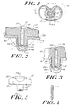
- Figure 1 is a top view, partially cut away, of a tibial component of a knee joint prosthesis system constructed according to the present invention.
- Figure 2 is a sectional view at lines 2-2 of the prosthesis system shown in Figure 1.
- Figure 3 is a sectional view at lines 3-3 of the joint prosthesis system shown in Figure 1.
- Figure 4 is a sectional view of a reinforcement pin useful with the joint prosthesis system of Figure 1.
- Figure 5 is a front view of a tibial bearing insert shown in the joint prosthesis system of Figure 1.
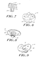
- Figure 6 is a perspective view of the tibial bearing insert of Figure 5.
- Figure 7 is a sectional view at lines 7-7 of the tibial bearing insert shown in Figure 5.
- Figure 8 is a perspective view of a tibial tray component of the joint prosthesis system shown in Figure 1.
- Figure 9 is a perspective view of the tibial tray component of a knee joint prosthesis system shown in Figure 1.
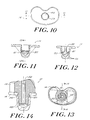
- Figure 10 is a top view of a tibial tray component of the knee joint prosthesis shown in Figure 1.
- Figure 11 is a sectional view of the tibial tray component of Figure 10 at Lines 11-11.
- Figure 12 is a sectional view of the tibial tray component of Figure 11 at Lines 12-12.
- Figure 13 is a top view, partially cut away, of a tibial component of a joint prosthesis system according to another embodiment of invention.
- Figure 14 is a sectional view of the tibial component of Figure 13 at Lines 14-14.
- The invention provides a
prosthesis system 10 that has first and second components that can be axially secured to one another while maintaining the ability of one component to rotate with respect to the other. For purposes of illustration thesystem 10 is shown as the tibial component of a knee joint prosthesis. It is understood, however, that the invention is applicable to other prostheses. - Referring to Figures 1-4, the
system 10 includes a first component in the form of atibial tray 14, upon which is mounted a second component, i.e.,tibial bearing insert 12. The mounting of the tibial bearing insert 12 to thetibial tray 14 is such that the tibial bearing insert is able to rotate with respect to the proximal orsuperior surface 32 of the tibial tray while remaining axially secured to the tibial tray. - The tibial bearing insert 12 has an
anterior side 13, aposterior side 15, asuperior articulation surface 16 and aninferior mating surface 18. Thesuperior surface 16 may have one or morecondylar elements 20 that are adapted to articulate with complementary condyle(s) of a femoral component (not shown) of a knee joint prosthesis. The inferior surface preferably includes amating stem 22 that protrudes from theinferior mating surface 18 and that is adapted to mate selectively withtibial tray 14. - The
tibial tray 14 includes ananterior side 17, aposterior side 19, asuperior mating surface 32 and an inferiorbone contacting surface 34. Thebone contacting surface 34 has afirst portion 36 that represents an area of the inferior surface that mounts upon the proximal surface of a resected tibia (not shown). Asecond portion 38 of thebone contacting surface 34 extends from thefirst portion 36 and is adapted to extend into a cavity (not shown) formed within a patient's tibia. Preferably, thesecond portion 38 is anelongate tibial stem 39 that extends from thefirst portion 36. Thetibial stem 39 has outer side anddistal walls outer side walls 40 of thetibial stem 39 may have irregular surface features (such as steps 42) to enhance bone fixation. - The
superior surface 32 of thetibial tray 14 includes an aperture 72 (which may be any suitable shape, e.g., substantially circular) that communicates with amating cavity 44. Themating cavity 44 preferably is a blind cavity, defined byinterior side walls 45, that extend into the tibial stem. Themating cavity 44 preferably terminates in an interiordistal wall 46 that may be substantially cone-shaped, or of another shape suitable to accept a tibial stem. - The mating stem 22 of the
tibial bearing insert 12 is adapted to fit within themating cavity 44 of the tibial tray. A locking mechanism ensures that themating stem 22 is secured within themating cavity 44 in such a way that the tibial bearing insert is axially secured to the tibial tray. Moreover, the tibial bearing insert must be able to rotate relative to the tibial tray while the two components are secured to one another. - One of ordinary skill in the art will readily appreciate that the dimensions of
cavity 44 and mating stem 22 may vary. In one embodiment thecavity 44 has a diameter that tapers from proximal 51 to distal 53 ends thereof at an angle in the range of about 0.25° to 5°. The diameter at theproximal end 51 is in the range of about 5 to 40 mm and the diameter at thedistal end 53 is in the range of about 3 to 39 mm. Thecavity 44 preferably has a depth in the range of about 5 to 75 mm. - The mating stem 22 should have a size and shape complementary to the
cavity 44. Accordingly, the diameter ofstem 22 should taper from about 6 to 38 mm at a proximal end to about 3 to 30 mm a distal end. The length ofstem 22 preferably is in the range of about 4 to 75 mm. - The
superior surface 16 of thetibial bearing insert 12 may optionally include ablind bore 52. The blind bore 52 is preferably substantially centrally located and is of a size and shape sufficient to receive areinforcement pin 54 of the type shown in Figure 4. Such reinforcement pins are well known in the art and may be substantially cylindrically shaped and made of a metal or metal alloy. Such pins may also have knurled or grooved surface features (not shown) as is known in the art. In one embodiment bore 52 is cylindrical, having a diameter of about 1 to 12 mm and a depth of about 5 to 75 mm. - The locking mechanism preferably is a bayonet-type locking mechanism that includes a non-deformable positive surface feature on one of the first or
second components second components second components second components - For purposes of illustration, the
tibial bearing insert 12 is shown to be the component having a non-deformablepositive surface feature 24 formed on themating stem 22. At least onepositive surface feature 24 is located on themating stem 22. Preferably, at least two positive surface features are present on the stem. As illustrated in Figures 3 and 5 through 7 the positive surface features 24 are opposite each other on anterior andposterior sides mating stem 22. Preferably the positive surface features 24 protrude from the side wall 30 of themating stem 22 by a distance in the range of about 0.25 to 8 mm. - Figures 5 through 7 and 9 illustrate an embodiment of the invention in which a
positive surface 24 feature is formed on themating stem 22 of thetibial bearing insert 12 and negative surface features are formed within themating cavity 44 of the tibial tray. As illustrated, the positive surface feature can be in the form of a raisedknob 56 that is formed on anterior andposterior sides 3, 15 of themating stem 22. Theknobs 56 can be substantially rectangularly-shaped, although one of ordinary skill in the art will readily appreciate that other shapes may be employed as well. The knobs protrude from the exterior wall of the mating stem by about 0.25 to 8 mm. Theknobs 56 may be located on a bottom portion of the mating stem, as shown in Figures 6 and 7, at a top portion of the mating stem as shown in Figure 14, or at intermediate positions. - The non-deformable positive surface features 24 on the
mating stem 22 protrude from the wall of themating stem 22 to the extent that they prevent the mating stem from being inserted within themating cavity 44 except through the negative surface features, as discussed below. The other dimensions of the positive surface features are not critical and can be readily, determined by one of ordinary skill in the art. - The
mating cavity 44 includes negative surface features that cooperate to allow themating stem 22 to be inserted within the mating cavity and to be secured therein. In one embodiment the mating cavity includes opposedaxial slots 58 that are formed inside wall 45 ofmating cavity 44.Axial slots 58 form access channels that enable themating stem 22 to be inserted withinmating cavity 44. Preferablyaxial slots 58 are of a sufficient depth to receive theknobs 56 of the mating stem. Further, theaxial slots 58 should be of a width that enables receipt of theknobs 56, while preventing any significant rotational movement of theknobs 56 when disposed within theaxial slots 58. In an embodiment in which theknobs 56 are mounted on opposed anterior and posterior surfaces of themating stem 22, the axially orientedslots 58 are disposed on opposed medial and lateral sides of the mating cavity. One of ordinary skill in the art can readily determine other suitable placement locations for theknobs 56 and theaxial slots 58. - As shown in Figures 1, 3 and 9, the
axial slots 58 terminate distally at acircumferential groove 60 which serves as a locking channel.Circumferential groove 60, likeaxial slot 58, has dimensions that are sufficient to receive theknobs 56. Thecircumferential groove 60 may be a single groove that extends continuously about the inner circumference of themating cavity 44. Alternatively, as one of ordinary skill in the art will appreciate, thecircumferential groove 60 may be comprise two or more non-continuous groove segments (not shown). - The
knobs 56,axial slots 58 andcircumferential groove 60 cooperate to form locking mechanism for theprosthesis system 10. This locking mechanism allows rotation of the tibial bearing insert 12 with respect to the tibial tray by travel of theknobs 56 withingroove 60. Simultaneously, thecircumferential groove 60 provides positive axial securement of the tibial bearing insert 12 within thetibial tray 14 when the tibial bearing insert is properly mounted within the tibial tray. This is accomplished by engaging the positive surface features (i.e., knobs 56) of the tibial bearing insert 12 within one of the negative surface features (i.e., circumferential groove 60) of the mating cavity. As noted above, theknobs 56 are preferably non-deformable and the relative dimensions of theknobs 56 andgroove 60 are such that theknobs 56 are engaged within thegroove 60 and cannot be removed fromgroove 60 except throughaxial slot 58. -
Circumferential groove 60 preferably is formed as a recess withininterior side wall 45 ofcavity 44. As such,circumferential groove 60 includes aproximal shoulder 61 or another suitable structure that is effective to maintain theknobs 56 withingroove 60. - As shown in Figures 10 through 14, other embodiments of the invention allow the
knobs 56 to be disposed at proximal and intermediate portions of the mating stem rather than at a distal end as in the embodiment shown in Figures 1 through 9. One of ordinary skill in the art will readily appreciate that only minor modifications to this prosthesis system need be made to accommodate the proximal placement of the knobs. For example, theaxial slot 58 will have a shorter length than the embodiments shown in Figures 1 through 9. Moreover, thecircumferentially groove 60 will be placed immediately distally of theaxial slots 58 and at a more proximal location on the mating cavity. - The
prosthesis system 10 may be assembled as follows. Assuming that the placement of positive and negative surface features is a shown in Figures 1-14, thetibial bearing insert 12 is oriented such that the anterior andposterior surfaces posterior surfaces knobs 56 to be disposed withinaxial slots 58 of themating cavity 44. Further, this orientation allows themating stem 22 of the tibial bearing insert 12 to be inserted within themating cavity 44, Once themating stem 22 is fully inserted, theknobs 56 extend beyond the distal end of the axially orientedslots 58 and communicate with thecircumferential groove 60. At this point, the tibial bearing insert can be rotated into its proper position in which the posterior and anterior sides of the tibial bearing insert and the tibial tray are aligned with one another. - When properly installed, the tibial bearing insert and the tibial tray are axially secured to one another. That is, the engagement of the
knobs 56 within thecircumferential groove 60 prevents axial separation of the components. Generally, the axially secured tibial bearing insert can withdstand an upwardly directed axial force of at least about 1 kg, and more preferably from about 14 kg to about 90 kg. The relative dimensions of thecircumferential groove 60 andknob 56 should be such that a clearance fit is achieved. That is, the tibial tray should be free to rotate with little or no friction, but substantially no vertical movement of the tibial bearing insert 12 relative to thetibial tray 24 should exist when theknobs 56 are engaged bycircumferential groove 60 and misaligned withslot 58. - One of ordinary skill in the art will appreciate that the components of the
system 10 of the invention can be made from a variety of known materials. The tibial bearing insert typically is made from a polymeric material, such as ultra high molecular weight polyethylene. The tibial bearing insert can be made of a variety of known metals and metal alloys that are suitable for implantable prostheses. - One of ordinary skill in the art will further appreciate that minor modifications may be made to the invention described herein without departing from its intended scope. All references noted herein are expressly incorporated by reference in their entirety.
Claims (22)
- A joint prosthesis system, comprising:a first component having a superior mounting surface and an inferior bone-contacting surface, the bone-contacting surface including an anchor stem having outer, implantable side and distal walls and interior side and distal walls;a cavity formed in the superior mounting surface and extending into the anchor stem, the cavity being defined by the inner side and distal walls of the anchor stem;a second component, having a superior articulation surface and an inferior surface mountable upon the mounting surface of the first component, the inferior surface including a mating stem being mountable within the cavity and having a shape and a size complementary to the cavity; anda selectively engagable locking mechanism including at least one non-deformable positive surface feature on one of the mating stem and the cavity and at least one cooperating negative surface feature on the other of the mating stem and the cavity, the locking mechanism being effective, when engaged, to permit rotation of the second component relative to the first component and to provide positive axial securement of the second component to the first component.
- The system of claim 1 wherein the first component is a tibial tray and the second component is a tibial bearing insert.
- The system of claim 2, further comprising:an axial bore formed in the superior surface of the tibial bearing insert and extending into the mating stem; anda reinforcement pin mountable within the axial bore in a frictional fit such that a proximal portion of the reinforcement pin does not protrude from the superior surface of the tibial bearing insert.
- The system of claim 1 wherein the at least one positive surface feature is formed on an exterior side wall of the mating stem and the at least one negative surface feature is disposed on the interior side wall of the cavity.
- The system of claim 4 wherein two positive surface features are disposed opposite one another on the exterior side wall of the mating stem.
- The system of claim 4 wherein the locking mechanism comprises:at least one axial slot formed in the interior side wall of the cavity;a circumferential groove formed in the cavity distally of and in communication with the axial slot;at least one positive surface feature protruding from the exterior side wall of the mating stem, the positive surface feature having dimensions sufficient to permit the mating stem to fit within the cavity only when the positive surface feature is aligned with the axial slot.
- The system of claim 6 wherein the circumferential groove is positioned to receive the positive surface feature upon full insertion of the mating stem within the cavity.
- The system of claim 7 wherein the circumferential groove includes at proximal end thereof a structure that is effective to prevent removal of the mating stem from the cavity when the positive surface feature is not in alignment within the axial slot.
- The system of claim 1 wherein the mating stem is an elongate member.
- The system of claim 9 wherein the mating stem has a length in the range of about 4 to 75 mm.
- The system of claim 10 wherein the cavity has a depth in the range of about 5 to 75 mm.
- The system of claim 1 wherein the cavity has a nominal diameter that tapers from a largest nominal diameter at a proximal portion of the cavity to a smallest nominal diameter at a distal portion of the cavity.
- The system of claim 12 wherein the nominal diameter of the cavity tapers at an angle in the range of about 0.25 to 5°.
- The system of claim 12 wherein the mating stem has a nominal diameter that tapers from a largest nominal diameter at a proximal portion of the mating stem to a smallest nominal diameter at a distal portion of the stem.
- The system of claim 14 wherein the shape and the nominal diameters of the mating stem and the cavity are complementary to one another.
- The system of claim 4 wherein the at least one positive surface feature is disposed on the exterior side wall of the mating stem at a location selected from the group consisting of a proximal portion of the mating stem, a distal portion of the mating stem and a portion of the mating stem intermediate the proximal and distal portions thereof.
- A joint prosthesis, comprising:a first component having a superior mounting surface and an inferior bone-contacting surface, the bone-contacting surface including an elongate anchor stem having outer, implantable side and distal walls and interior side and distal walls;a cavity formed in the superior mounting surface and extending into the anchor stem, the cavity being defined by the inner side and distal walls of the anchor stem;a second component, having a superior articulation surface and an inferior surface mountable upon the mounting surface of the first component, the inferior surface including an elongate mating stem mountable within the cavity and having a shape complementary to the cavity; andcooperating non-deformable locking means, integrally formed on the mating stem and the cavity, for providing selective axial securement of the mating stem within the cavity while allowing rotation of the second component relative to the first component in the medial-lateral plane.
- The system of claim 17 wherein the locking means is a bayonet-type locking mechanism having at least one male locking component formed on the exterior wall of the mating stem and at least one female locking component formed on the cavity.
- The system of claim 17 wherein the first component is a tibial tray and the second component is a tibial bearing insert.
- The system of claim 19, further comprising:an axial bore formed in the superior surface of the tibial bearing insert and extending into the mating stem; anda reinforcement pin mountable within the axial bore in a frictional fit such that a proximal portion of the reinforcement pin does not protrude from the superior surface of the tibial bearing insert.
- A joint prosthesis, comprising:a first component having a superior mounting surface and an inferior bone-contacting surface, the bone-contacting surface including an elongate anchor stem having outer, implantable side and distal walls and interior side and distal walls;a cavity formed in the superior mounting surface and extending into the anchor stem, the cavity being defined by the inner side and the distal walls of the anchor stem;a second component, having a superior articulation surface and an inferior surface rotatably mounted upon the mounting surface of the first component, the inferior surface including mating stem rotatably mounted within the cavity and having a shape and a size complementary to the cavity; anda locking mechanism including at least one non-deformable positive surface feature on the mating stem and at least one cooperating negative surface feature on the other of the mating stem and the cavity, the locking mechanism being effective, when engaged, to permit axial rotation in the medial-lateral plane of the second component relative to the first component and to provide positive axial securement of the second component to the first component.
- The joint prosthesis of claim 21, wherein the first component is a tibial tray and the second component is a tibial bearing insert.
Applications Claiming Priority (2)
| Application Number | Priority Date | Filing Date | Title |
|---|---|---|---|
| US08/937,965 US6010534A (en) | 1997-09-25 | 1997-09-25 | Rotatable tibial prosthesis with keyed axial securement |
| US937965 | 1997-09-25 |
Publications (3)
| Publication Number | Publication Date |
|---|---|
| EP0904748A2 true EP0904748A2 (en) | 1999-03-31 |
| EP0904748A3 EP0904748A3 (en) | 2000-01-05 |
| EP0904748B1 EP0904748B1 (en) | 2005-12-21 |
Family
ID=25470644
Family Applications (1)
| Application Number | Title | Priority Date | Filing Date |
|---|---|---|---|
| EP98307768A Expired - Lifetime EP0904748B1 (en) | 1997-09-25 | 1998-09-24 | Joint prosthesis system with a rotatable component having a keyed axial securement |
Country Status (3)
| Country | Link |
|---|---|
| US (1) | US6010534A (en) |
| EP (1) | EP0904748B1 (en) |
| DE (1) | DE69832861T2 (en) |
Cited By (6)
| Publication number | Priority date | Publication date | Assignee | Title |
|---|---|---|---|---|
| WO2003094804A2 (en) * | 2002-05-14 | 2003-11-20 | Peter Brehm | Tibia component and sliding plate of a knee-joint endoprothesis |
| EP1591083A1 (en) * | 2004-04-28 | 2005-11-02 | Buechel-Pappas Trust | Prosthetic knee |
| WO2008045863A1 (en) * | 2006-10-13 | 2008-04-17 | Depuy Products, Inc. | Mobile/fixed prosthetic knee systems |
| US7740662B2 (en) | 2006-10-13 | 2010-06-22 | Depuy Products, Inc. | Mobile/fixed prosthetic knee systems |
| US8403993B2 (en) | 2005-10-31 | 2013-03-26 | Depuy Products, Inc. | Modular fixed and mobile bearing prosthesis system |
| US9211189B2 (en) | 2008-11-14 | 2015-12-15 | Zimmer, Inc. | Transiently mobile tibial engagement |
Families Citing this family (56)
| Publication number | Priority date | Publication date | Assignee | Title |
|---|---|---|---|---|
| US6296666B1 (en) | 2000-03-13 | 2001-10-02 | Encore Medical Corporation | Mobile bearing knee with center post |
| US6447549B1 (en) | 2000-10-06 | 2002-09-10 | Sulzer Orthopedics Inc. | Modular knee prosthesis system |
| US6558426B1 (en) | 2000-11-28 | 2003-05-06 | Medidea, Llc | Multiple-cam, posterior-stabilized knee prosthesis |
| US6355037B1 (en) | 2000-12-05 | 2002-03-12 | Smith & Nephew, Inc. | Apparatus and method of external skeletal support allowing for internal-external rotation |
| US20030009230A1 (en) * | 2001-06-30 | 2003-01-09 | Gundlapalli Rama Rao V. | Surface sterilizable joint replacement prosthesis component with insert |
| ES2399084T3 (en) * | 2002-02-20 | 2013-03-25 | Zimmer, Inc. | Knee arthroplasty prosthesis |
| EP1601316A1 (en) * | 2003-02-04 | 2005-12-07 | Zimmer Austin, Inc. | Rotating/non-rotating tibia plate/insert system |
| US7691149B2 (en) * | 2006-05-15 | 2010-04-06 | Biomet Manufacturing Corp. | Porous titanium modular revision patella system |
| US20080091273A1 (en) * | 2006-10-13 | 2008-04-17 | Hazebrouck Stephen A | Mobile/fixed prosthetic knee systems |
| US20080114463A1 (en) * | 2006-10-13 | 2008-05-15 | Auger Daniel D | Mobile/fixed prosthetic knee systems |
| JP5448842B2 (en) * | 2007-01-10 | 2014-03-19 | バイオメト マニファクチャリング コーポレイション | Knee joint prosthesis system and implantation method |
| US8187280B2 (en) | 2007-10-10 | 2012-05-29 | Biomet Manufacturing Corp. | Knee joint prosthesis system and method for implantation |
| US8163028B2 (en) * | 2007-01-10 | 2012-04-24 | Biomet Manufacturing Corp. | Knee joint prosthesis system and method for implantation |
| US8562616B2 (en) * | 2007-10-10 | 2013-10-22 | Biomet Manufacturing, Llc | Knee joint prosthesis system and method for implantation |
| US8328873B2 (en) | 2007-01-10 | 2012-12-11 | Biomet Manufacturing Corp. | Knee joint prosthesis system and method for implantation |
| US8147557B2 (en) * | 2007-03-30 | 2012-04-03 | Depuy Products, Inc. | Mobile bearing insert having offset dwell point |
| US8328874B2 (en) * | 2007-03-30 | 2012-12-11 | Depuy Products, Inc. | Mobile bearing assembly |
| US8147558B2 (en) * | 2007-03-30 | 2012-04-03 | Depuy Products, Inc. | Mobile bearing assembly having multiple articulation interfaces |
| US8142510B2 (en) * | 2007-03-30 | 2012-03-27 | Depuy Products, Inc. | Mobile bearing assembly having a non-planar interface |
| US8764841B2 (en) * | 2007-03-30 | 2014-07-01 | DePuy Synthes Products, LLC | Mobile bearing assembly having a closed track |
| US8632600B2 (en) | 2007-09-25 | 2014-01-21 | Depuy (Ireland) | Prosthesis with modular extensions |
| US8128703B2 (en) | 2007-09-28 | 2012-03-06 | Depuy Products, Inc. | Fixed-bearing knee prosthesis having interchangeable components |
| US9204967B2 (en) | 2007-09-28 | 2015-12-08 | Depuy (Ireland) | Fixed-bearing knee prosthesis having interchangeable components |
| US8206451B2 (en) | 2008-06-30 | 2012-06-26 | Depuy Products, Inc. | Posterior stabilized orthopaedic prosthesis |
| US9119723B2 (en) | 2008-06-30 | 2015-09-01 | Depuy (Ireland) | Posterior stabilized orthopaedic prosthesis assembly |
| US8828086B2 (en) | 2008-06-30 | 2014-09-09 | Depuy (Ireland) | Orthopaedic femoral component having controlled condylar curvature |
| US8236061B2 (en) | 2008-06-30 | 2012-08-07 | Depuy Products, Inc. | Orthopaedic knee prosthesis having controlled condylar curvature |
| US9168145B2 (en) | 2008-06-30 | 2015-10-27 | Depuy (Ireland) | Posterior stabilized orthopaedic knee prosthesis having controlled condylar curvature |
| US8192498B2 (en) | 2008-06-30 | 2012-06-05 | Depuy Products, Inc. | Posterior cructiate-retaining orthopaedic knee prosthesis having controlled condylar curvature |
| US8187335B2 (en) | 2008-06-30 | 2012-05-29 | Depuy Products, Inc. | Posterior stabilized orthopaedic knee prosthesis having controlled condylar curvature |
| US8696754B2 (en) * | 2008-09-03 | 2014-04-15 | Biomet Manufacturing, Llc | Revision patella prosthesis |
| US9011547B2 (en) * | 2010-01-21 | 2015-04-21 | Depuy (Ireland) | Knee prosthesis system |
| US9381090B2 (en) * | 2010-07-24 | 2016-07-05 | Zimmer, Inc. | Asymmetric tibial components for a knee prosthesis |
| EP3034042B1 (en) | 2010-07-24 | 2017-06-28 | Zimmer, Inc. | Asymmetric tibial components for a knee prosthesis |
| US8764840B2 (en) | 2010-07-24 | 2014-07-01 | Zimmer, Inc. | Tibial prosthesis |
| US8591594B2 (en) | 2010-09-10 | 2013-11-26 | Zimmer, Inc. | Motion facilitating tibial components for a knee prosthesis |
| US8317870B2 (en) | 2010-09-30 | 2012-11-27 | Depuy Products, Inc. | Tibial component of a knee prosthesis having an angled cement pocket |
| US8287601B2 (en) | 2010-09-30 | 2012-10-16 | Depuy Products, Inc. | Femoral component of a knee prosthesis having an angled cement pocket |
| US8603101B2 (en) | 2010-12-17 | 2013-12-10 | Zimmer, Inc. | Provisional tibial prosthesis system |
| CN104066402B (en) | 2011-11-18 | 2016-05-04 | 捷迈有限公司 | For the shin bone support member with improved articulation feature of knee-joint prosthesis |
| ES2585838T3 (en) | 2011-11-21 | 2016-10-10 | Zimmer, Inc. | Tibial base plate with asymmetric placement of fixing structures |
| US9011444B2 (en) | 2011-12-09 | 2015-04-21 | Howmedica Osteonics Corp. | Surgical reaming instrument for shaping a bone cavity |
| AU2012362279A1 (en) | 2011-12-30 | 2014-07-24 | Howmedica Osteonics Corp. | Systems for preparing bone voids to receive a prosthesis |
| US8721733B2 (en) * | 2012-05-14 | 2014-05-13 | Depuy (Ireland) | Prosthesis kit with finned sleeve |
| US8961612B2 (en) | 2012-08-30 | 2015-02-24 | Biomet Manufacturing, Llc | Knee component having orbital interface boss |
| US9526513B2 (en) | 2013-03-13 | 2016-12-27 | Howmedica Osteonics Corp. | Void filling joint prosthesis and associated instruments |
| US9925052B2 (en) | 2013-08-30 | 2018-03-27 | Zimmer, Inc. | Method for optimizing implant designs |
| EP3142609B1 (en) | 2014-05-12 | 2018-03-21 | Integra LifeSciences Corporation | Total ankle replacement prosthesis |
| US10299929B2 (en) | 2015-01-12 | 2019-05-28 | Howmedica Osteonics Corp. | Bone void forming apparatus |
| CN108135701B (en) | 2015-09-21 | 2019-12-24 | 捷迈有限公司 | Prosthesis system including tibial bearing component |
| US10231840B2 (en) | 2016-07-27 | 2019-03-19 | Howmedica Osteonics Corp. | Low profile tibial baseplate with fixation members |
| US10675153B2 (en) | 2017-03-10 | 2020-06-09 | Zimmer, Inc. | Tibial prosthesis with tibial bearing component securing feature |
| CA3063415C (en) | 2017-05-12 | 2021-10-19 | Zimmer, Inc. | Femoral prostheses with upsizing and downsizing capabilities |
| US11426282B2 (en) | 2017-11-16 | 2022-08-30 | Zimmer, Inc. | Implants for adding joint inclination to a knee arthroplasty |
| US10835380B2 (en) | 2018-04-30 | 2020-11-17 | Zimmer, Inc. | Posterior stabilized prosthesis system |
| US11903838B2 (en) | 2018-11-09 | 2024-02-20 | Signature Orthopaedics Europe Ltd | Revision knee system |
Citations (6)
| Publication number | Priority date | Publication date | Assignee | Title |
|---|---|---|---|---|
| US4219893A (en) | 1977-09-01 | 1980-09-02 | United States Surgical Corporation | Prosthetic knee joint |
| US4301553A (en) | 1975-08-15 | 1981-11-24 | United States Surgical Corporation | Prosthetic knee joint |
| US5059216A (en) | 1989-09-29 | 1991-10-22 | Winters Thomas F | Knee joint replacement apparatus |
| US5071438A (en) | 1990-11-07 | 1991-12-10 | Intermedics Orthopedics, Inc. | Tibial prothesis with pivoting articulating surface |
| US5171283A (en) | 1989-07-11 | 1992-12-15 | Biomedical Engineering Trust | Compound shape rotating bearing |
| US5489311A (en) | 1994-01-21 | 1996-02-06 | Joint Medical Products Corporation | Prosthesis with orientable bearing surface |
Family Cites Families (38)
| Publication number | Priority date | Publication date | Assignee | Title |
|---|---|---|---|---|
| US4136405A (en) * | 1977-04-29 | 1979-01-30 | Zimmer U.S.A. | Rotational offset knee prosthesis |
| DE2965891D1 (en) * | 1978-03-10 | 1983-08-25 | Biomedical Eng Corp | Improved joint endoprosthesis |
| DE3173192D1 (en) * | 1980-09-03 | 1986-01-23 | Link Waldemar Gmbh Co | Knee joint endoprosthesis |
| DE3119841A1 (en) * | 1981-05-19 | 1982-12-16 | GMT GESELLSCHAFT FüR MEDIZINISCHE TECHNIK MBH | ENDOPROTHESIS OF A KNEE JOINT |
| DE3136636A1 (en) * | 1981-09-16 | 1983-03-31 | Waldemar Link (Gmbh & Co), 2000 Hamburg | Tibial plateau made of plastic with a baseplate of hard material |
| DE3138848A1 (en) * | 1981-09-30 | 1983-04-21 | GMT GESELLSCHAFT FüR MEDIZINISCHE TECHNIK MBH | ENDOPROTHESIS TO REPLACE ROD-SHAPED BONES |
| DE3431645A1 (en) * | 1984-08-29 | 1986-03-13 | GMT GESELLSCHAFT FüR MEDIZINISCHE TECHNIK MBH | ENDOPROTHESIS |
| SE450460B (en) * | 1984-11-28 | 1987-06-29 | Albrektsson Bjoern | DEVICE IN ARTIFICIAL MENISH FOR A KNEE JOINT PROTECTION |
| GB8432267D0 (en) * | 1984-12-20 | 1985-01-30 | Thackray C F Ltd | Knee prosthesis |
| FR2601873B1 (en) * | 1986-07-25 | 1994-07-01 | Cuilleron J | TOTAL INTRACONDYLIAN KNEE PROSTHESIS |
| US5011496A (en) * | 1988-02-02 | 1991-04-30 | Joint Medical Products Corporation | Prosthetic joint |
| US4888021A (en) * | 1988-02-02 | 1989-12-19 | Joint Medical Products Corporation | Knee and patellar prosthesis |
| FR2631814A1 (en) * | 1988-05-31 | 1989-12-01 | Scernp | SLIDING KNEE PROSTHESIS |
| GB9005496D0 (en) * | 1990-03-12 | 1990-05-09 | Howmedica | Tibial component for a replacement knee prosthesis and total knee prosthesis incorporating such a component |
| US5370701A (en) * | 1990-09-28 | 1994-12-06 | Arch Development Corporation | Rotating/sliding contrained prosthetic knee |
| CA2078228C (en) * | 1990-11-14 | 2000-04-11 | Lawrence Pottenger | Improved floating bearing prosthetic knee |
| GB9102348D0 (en) * | 1991-02-04 | 1991-03-20 | Inst Of Orthopaedics The | Prosthesis for knee replacement |
| US5395401A (en) * | 1991-06-17 | 1995-03-07 | Bahler; Andre | Prosthetic device for a complex joint |
| US5282868A (en) * | 1991-06-17 | 1994-02-01 | Andre Bahler | Prosthetic arrangement for a complex joint, especially knee joint |
| ES2161804T3 (en) * | 1991-06-17 | 2001-12-16 | Andre Bahler | PROTESIS FOR AN ARTICULATION, IN SPECIAL PROTESIS FOR THE ARTICULATION OF THE KNEE. |
| DE4128171C1 (en) * | 1991-08-24 | 1993-04-01 | Aesculap Ag, 7200 Tuttlingen, De | |
| DE59209628D1 (en) * | 1992-01-14 | 1999-03-11 | Sulzer Orthopaedie Ag | Meniscal platform for artificial knee joint |
| NZ243181A (en) * | 1992-04-23 | 1994-10-26 | Michael John Pappas | Prosthetic joint with guide means to limit articulation of a first element and bearing means to two degrees of freedom |
| DE9212879U1 (en) * | 1992-09-24 | 1994-01-27 | Link Waldemar Gmbh Co | Knee joint endoprosthesis to replace the shin joint surfaces |
| US5370699A (en) * | 1993-01-21 | 1994-12-06 | Orthomet, Inc. | Modular knee joint prosthesis |
| EP0627202B1 (en) * | 1993-04-05 | 1998-06-24 | Procom S.A. | Prosthetic assembly for forming a knee joint |
| GB9314832D0 (en) * | 1993-07-16 | 1993-09-01 | Walker Peter S | Prostheses for knee replacement |
| IT1264820B1 (en) * | 1993-07-28 | 1996-10-10 | Cremascoli G Srl | TOTAL KNEE PROSTHESIS TOTAL KNEE PROSTHESIS |
| EP0689406A1 (en) * | 1993-12-30 | 1996-01-03 | Bruno E. Dr. Gerber | Knee endoprosthesis |
| DE4409787A1 (en) * | 1994-03-22 | 1995-09-28 | Alphanorm Medizintechnik Gmbh | Knee prosthesis |
| GB9405883D0 (en) * | 1994-03-24 | 1994-05-11 | Corin Medical Ltd | Prosthesis assembly |
| FR2719466B1 (en) * | 1994-05-04 | 1997-06-06 | Ysebaert Sa | Knee prosthesis with movable meniscus. |
| FR2721820B1 (en) * | 1994-06-30 | 1996-12-13 | Ysebaert Sa | KNEE PROSTHETIC JOINT, IN PARTICULAR ONE-COMPARTMENTAL KNEE PROSTHESIS, OR JOINT PROSTHESIS |
| GB9415180D0 (en) * | 1994-07-28 | 1994-09-21 | Walker Peter S | Stabilised mobile bearing knee |
| FR2726174B1 (en) * | 1994-10-26 | 1997-04-04 | Cornic Michel | KNEE JOINT PROSTHESIS |
| FR2728782B1 (en) * | 1994-12-30 | 1998-10-16 | Jbs Sa | KNEE PROSTHESIS |
| US5683468A (en) * | 1995-03-13 | 1997-11-04 | Pappas; Michael J. | Mobile bearing total joint replacement |
| US5871543A (en) * | 1996-02-23 | 1999-02-16 | Hofmann; Aaron A. | Tibial prosthesis with mobile bearing member |
-
1997
- 1997-09-25 US US08/937,965 patent/US6010534A/en not_active Expired - Lifetime
-
1998
- 1998-09-24 EP EP98307768A patent/EP0904748B1/en not_active Expired - Lifetime
- 1998-09-24 DE DE69832861T patent/DE69832861T2/en not_active Expired - Lifetime
Patent Citations (6)
| Publication number | Priority date | Publication date | Assignee | Title |
|---|---|---|---|---|
| US4301553A (en) | 1975-08-15 | 1981-11-24 | United States Surgical Corporation | Prosthetic knee joint |
| US4219893A (en) | 1977-09-01 | 1980-09-02 | United States Surgical Corporation | Prosthetic knee joint |
| US5171283A (en) | 1989-07-11 | 1992-12-15 | Biomedical Engineering Trust | Compound shape rotating bearing |
| US5059216A (en) | 1989-09-29 | 1991-10-22 | Winters Thomas F | Knee joint replacement apparatus |
| US5071438A (en) | 1990-11-07 | 1991-12-10 | Intermedics Orthopedics, Inc. | Tibial prothesis with pivoting articulating surface |
| US5489311A (en) | 1994-01-21 | 1996-02-06 | Joint Medical Products Corporation | Prosthesis with orientable bearing surface |
Cited By (11)
| Publication number | Priority date | Publication date | Assignee | Title |
|---|---|---|---|---|
| WO2003094804A2 (en) * | 2002-05-14 | 2003-11-20 | Peter Brehm | Tibia component and sliding plate of a knee-joint endoprothesis |
| DE10221272A1 (en) * | 2002-05-14 | 2003-11-27 | Peter Brehm | Tibial component and sliding plate of a knee joint endoprosthesis |
| WO2003094804A3 (en) * | 2002-05-14 | 2004-02-26 | Peter Brehm | Tibia component and sliding plate of a knee-joint endoprothesis |
| US7470289B2 (en) | 2002-05-14 | 2008-12-30 | Peter Brehm | Tibia component and sliding plate of a knee-joint endoprosthesis |
| EP1591083A1 (en) * | 2004-04-28 | 2005-11-02 | Buechel-Pappas Trust | Prosthetic knee |
| US8403993B2 (en) | 2005-10-31 | 2013-03-26 | Depuy Products, Inc. | Modular fixed and mobile bearing prosthesis system |
| WO2008045863A1 (en) * | 2006-10-13 | 2008-04-17 | Depuy Products, Inc. | Mobile/fixed prosthetic knee systems |
| US7740662B2 (en) | 2006-10-13 | 2010-06-22 | Depuy Products, Inc. | Mobile/fixed prosthetic knee systems |
| US8105387B2 (en) | 2006-10-13 | 2012-01-31 | Depuy Products, Inc. | Mobile/fixed prosthetic knee systems |
| EP2412338A1 (en) * | 2006-10-13 | 2012-02-01 | DePuy Products, Inc. | Mobile/fixed prosthetic knee systems |
| US9211189B2 (en) | 2008-11-14 | 2015-12-15 | Zimmer, Inc. | Transiently mobile tibial engagement |
Also Published As
| Publication number | Publication date |
|---|---|
| DE69832861T2 (en) | 2006-08-17 |
| DE69832861D1 (en) | 2006-01-26 |
| EP0904748B1 (en) | 2005-12-21 |
| EP0904748A3 (en) | 2000-01-05 |
| US6010534A (en) | 2000-01-04 |
Similar Documents
| Publication | Publication Date | Title |
|---|---|---|
| US6010534A (en) | Rotatable tibial prosthesis with keyed axial securement | |
| EP0904750B1 (en) | Rotatable joint prosthesis with axial securement | |
| EP0970667B1 (en) | Rotatable and translatable joint prosthesis with posterior stabilization | |
| US6053945A (en) | Joint prosthesis having controlled rotation | |
| EP1025818B1 (en) | Modular joint prosthesis system | |
| EP1023881B1 (en) | Modular tibial insert for prosthesis system | |
| EP0980679B1 (en) | Femoral component of a modular knee prosthesis | |
| US5019103A (en) | Tibial wedge system | |
| EP0986994B1 (en) | Tapped box femoral stem attachment for a modular knee prosthesis | |
| EP0797417B1 (en) | Knee prosthesis with shims | |
| US5766257A (en) | Artificial joint having natural load transfer | |
| US5571194A (en) | Femoral augmentation system for artificial knee joint | |
| US6290725B1 (en) | Modular elbow | |
| EP0781117B1 (en) | Prosthetic knee joint device | |
| EP0913133B1 (en) | Modular elbow prosthesis | |
| US20090149963A1 (en) | Prosthesis assembly including angle and position adaptors | |
| EP0985386A2 (en) | Femoral stem attachment for a modular knee prosthesis | |
| US20050154470A1 (en) | Modular phrosthesis assembly including tapered adjustments | |
| EP0993813A2 (en) | Stem offset mechanism for joint prosthesis | |
| AU2022200958A1 (en) | System and method for preparing a patient's femur in an orthopaedic joint replacement procedure | |
| IE58925B1 (en) | Knee prosthesis | |
| EP3049027B1 (en) | Reverse knee prosthesis |
Legal Events
| Date | Code | Title | Description |
|---|---|---|---|
| PUAI | Public reference made under article 153(3) epc to a published international application that has entered the european phase |
Free format text: ORIGINAL CODE: 0009012 |
|
| AK | Designated contracting states |
Kind code of ref document: A2 Designated state(s): DE GB |
|
| AX | Request for extension of the european patent |
Free format text: AL;LT;LV;MK;RO;SI |
|
| PUAL | Search report despatched |
Free format text: ORIGINAL CODE: 0009013 |
|
| AK | Designated contracting states |
Kind code of ref document: A3 Designated state(s): AT BE CH CY DE DK ES FI FR GB GR IE IT LI LU MC NL PT SE |
|
| AX | Request for extension of the european patent |
Free format text: AL;LT;LV;MK;RO;SI |
|
| 17P | Request for examination filed |
Effective date: 20000613 |
|
| AKX | Designation fees paid |
Free format text: DE GB |
|
| RAP1 | Party data changed (applicant data changed or rights of an application transferred) |
Owner name: DEPUY PRODUCTS, INC. |
|
| RAP1 | Party data changed (applicant data changed or rights of an application transferred) |
Owner name: DEPUY PRODUCTS, INC. |
|
| 17Q | First examination report despatched |
Effective date: 20040428 |
|
| GRAP | Despatch of communication of intention to grant a patent |
Free format text: ORIGINAL CODE: EPIDOSNIGR1 |
|
| RIC1 | Information provided on ipc code assigned before grant |
Ipc: 7A 61F 2/38 B Ipc: 7A 61F 2/30 A |
|
| RTI1 | Title (correction) |
Free format text: JOINT PROSTHESIS SYSTEM WITH A ROTATABLE COMPONENT HAVING A KEYED AXIAL SECUREMENT |
|
| GRAS | Grant fee paid |
Free format text: ORIGINAL CODE: EPIDOSNIGR3 |
|
| GRAA | (expected) grant |
Free format text: ORIGINAL CODE: 0009210 |
|
| AK | Designated contracting states |
Kind code of ref document: B1 Designated state(s): DE GB |
|
| REG | Reference to a national code |
Ref country code: GB Ref legal event code: FG4D |
|
| REF | Corresponds to: |
Ref document number: 69832861 Country of ref document: DE Date of ref document: 20060126 Kind code of ref document: P |
|
| PLBE | No opposition filed within time limit |
Free format text: ORIGINAL CODE: 0009261 |
|
| STAA | Information on the status of an ep patent application or granted ep patent |
Free format text: STATUS: NO OPPOSITION FILED WITHIN TIME LIMIT |
|
| 26N | No opposition filed |
Effective date: 20060922 |
|
| PGFP | Annual fee paid to national office [announced via postgrant information from national office to epo] |
Ref country code: DE Payment date: 20130918 Year of fee payment: 16 |
|
| PGFP | Annual fee paid to national office [announced via postgrant information from national office to epo] |
Ref country code: GB Payment date: 20130918 Year of fee payment: 16 |
|
| REG | Reference to a national code |
Ref country code: DE Ref legal event code: R119 Ref document number: 69832861 Country of ref document: DE |
|
| GBPC | Gb: european patent ceased through non-payment of renewal fee |
Effective date: 20140924 |
|
| PG25 | Lapsed in a contracting state [announced via postgrant information from national office to epo] |
Ref country code: DE Free format text: LAPSE BECAUSE OF NON-PAYMENT OF DUE FEES Effective date: 20150401 Ref country code: GB Free format text: LAPSE BECAUSE OF NON-PAYMENT OF DUE FEES Effective date: 20140924 |