EP0904750A2 - Rotatable joint prosthesis with axial securement - Google Patents
Rotatable joint prosthesis with axial securement Download PDFInfo
- Publication number
- EP0904750A2 EP0904750A2 EP98307772A EP98307772A EP0904750A2 EP 0904750 A2 EP0904750 A2 EP 0904750A2 EP 98307772 A EP98307772 A EP 98307772A EP 98307772 A EP98307772 A EP 98307772A EP 0904750 A2 EP0904750 A2 EP 0904750A2
- Authority
- EP
- European Patent Office
- Prior art keywords
- component
- surface feature
- feature
- tibial
- bearing insert
- Prior art date
- Legal status (The legal status is an assumption and is not a legal conclusion. Google has not performed a legal analysis and makes no representation as to the accuracy of the status listed.)
- Granted
Links
Images


Classifications
-
- A—HUMAN NECESSITIES
- A61—MEDICAL OR VETERINARY SCIENCE; HYGIENE
- A61F—FILTERS IMPLANTABLE INTO BLOOD VESSELS; PROSTHESES; DEVICES PROVIDING PATENCY TO, OR PREVENTING COLLAPSING OF, TUBULAR STRUCTURES OF THE BODY, e.g. STENTS; ORTHOPAEDIC, NURSING OR CONTRACEPTIVE DEVICES; FOMENTATION; TREATMENT OR PROTECTION OF EYES OR EARS; BANDAGES, DRESSINGS OR ABSORBENT PADS; FIRST-AID KITS
- A61F2/00—Filters implantable into blood vessels; Prostheses, i.e. artificial substitutes or replacements for parts of the body; Appliances for connecting them with the body; Devices providing patency to, or preventing collapsing of, tubular structures of the body, e.g. stents
- A61F2/02—Prostheses implantable into the body
- A61F2/30—Joints
- A61F2/38—Joints for elbows or knees
- A61F2/3868—Joints for elbows or knees with sliding tibial bearing
-
- A—HUMAN NECESSITIES
- A61—MEDICAL OR VETERINARY SCIENCE; HYGIENE
- A61F—FILTERS IMPLANTABLE INTO BLOOD VESSELS; PROSTHESES; DEVICES PROVIDING PATENCY TO, OR PREVENTING COLLAPSING OF, TUBULAR STRUCTURES OF THE BODY, e.g. STENTS; ORTHOPAEDIC, NURSING OR CONTRACEPTIVE DEVICES; FOMENTATION; TREATMENT OR PROTECTION OF EYES OR EARS; BANDAGES, DRESSINGS OR ABSORBENT PADS; FIRST-AID KITS
- A61F2/00—Filters implantable into blood vessels; Prostheses, i.e. artificial substitutes or replacements for parts of the body; Appliances for connecting them with the body; Devices providing patency to, or preventing collapsing of, tubular structures of the body, e.g. stents
- A61F2/02—Prostheses implantable into the body
- A61F2/30—Joints
- A61F2002/30001—Additional features of subject-matter classified in A61F2/28, A61F2/30 and subgroups thereof
- A61F2002/30108—Shapes
- A61F2002/30199—Three-dimensional shapes
- A61F2002/30224—Three-dimensional shapes cylindrical
- A61F2002/30233—Stepped cylinders, i.e. having discrete diameter changes
-
- A—HUMAN NECESSITIES
- A61—MEDICAL OR VETERINARY SCIENCE; HYGIENE
- A61F—FILTERS IMPLANTABLE INTO BLOOD VESSELS; PROSTHESES; DEVICES PROVIDING PATENCY TO, OR PREVENTING COLLAPSING OF, TUBULAR STRUCTURES OF THE BODY, e.g. STENTS; ORTHOPAEDIC, NURSING OR CONTRACEPTIVE DEVICES; FOMENTATION; TREATMENT OR PROTECTION OF EYES OR EARS; BANDAGES, DRESSINGS OR ABSORBENT PADS; FIRST-AID KITS
- A61F2/00—Filters implantable into blood vessels; Prostheses, i.e. artificial substitutes or replacements for parts of the body; Appliances for connecting them with the body; Devices providing patency to, or preventing collapsing of, tubular structures of the body, e.g. stents
- A61F2/02—Prostheses implantable into the body
- A61F2/30—Joints
- A61F2002/30001—Additional features of subject-matter classified in A61F2/28, A61F2/30 and subgroups thereof
- A61F2002/30316—The prosthesis having different structural features at different locations within the same prosthesis; Connections between prosthetic parts; Special structural features of bone or joint prostheses not otherwise provided for
- A61F2002/30329—Connections or couplings between prosthetic parts, e.g. between modular parts; Connecting elements
- A61F2002/30331—Connections or couplings between prosthetic parts, e.g. between modular parts; Connecting elements made by longitudinally pushing a protrusion into a complementarily-shaped recess, e.g. held by friction fit
- A61F2002/30332—Conically- or frustoconically-shaped protrusion and recess
-
- A—HUMAN NECESSITIES
- A61—MEDICAL OR VETERINARY SCIENCE; HYGIENE
- A61F—FILTERS IMPLANTABLE INTO BLOOD VESSELS; PROSTHESES; DEVICES PROVIDING PATENCY TO, OR PREVENTING COLLAPSING OF, TUBULAR STRUCTURES OF THE BODY, e.g. STENTS; ORTHOPAEDIC, NURSING OR CONTRACEPTIVE DEVICES; FOMENTATION; TREATMENT OR PROTECTION OF EYES OR EARS; BANDAGES, DRESSINGS OR ABSORBENT PADS; FIRST-AID KITS
- A61F2/00—Filters implantable into blood vessels; Prostheses, i.e. artificial substitutes or replacements for parts of the body; Appliances for connecting them with the body; Devices providing patency to, or preventing collapsing of, tubular structures of the body, e.g. stents
- A61F2/02—Prostheses implantable into the body
- A61F2/30—Joints
- A61F2002/30001—Additional features of subject-matter classified in A61F2/28, A61F2/30 and subgroups thereof
- A61F2002/30316—The prosthesis having different structural features at different locations within the same prosthesis; Connections between prosthetic parts; Special structural features of bone or joint prostheses not otherwise provided for
- A61F2002/30329—Connections or couplings between prosthetic parts, e.g. between modular parts; Connecting elements
- A61F2002/30476—Connections or couplings between prosthetic parts, e.g. between modular parts; Connecting elements locked by an additional locking mechanism
- A61F2002/305—Snap connection
-
- A—HUMAN NECESSITIES
- A61—MEDICAL OR VETERINARY SCIENCE; HYGIENE
- A61F—FILTERS IMPLANTABLE INTO BLOOD VESSELS; PROSTHESES; DEVICES PROVIDING PATENCY TO, OR PREVENTING COLLAPSING OF, TUBULAR STRUCTURES OF THE BODY, e.g. STENTS; ORTHOPAEDIC, NURSING OR CONTRACEPTIVE DEVICES; FOMENTATION; TREATMENT OR PROTECTION OF EYES OR EARS; BANDAGES, DRESSINGS OR ABSORBENT PADS; FIRST-AID KITS
- A61F2/00—Filters implantable into blood vessels; Prostheses, i.e. artificial substitutes or replacements for parts of the body; Appliances for connecting them with the body; Devices providing patency to, or preventing collapsing of, tubular structures of the body, e.g. stents
- A61F2/02—Prostheses implantable into the body
- A61F2/30—Joints
- A61F2002/30001—Additional features of subject-matter classified in A61F2/28, A61F2/30 and subgroups thereof
- A61F2002/30316—The prosthesis having different structural features at different locations within the same prosthesis; Connections between prosthetic parts; Special structural features of bone or joint prostheses not otherwise provided for
- A61F2002/30535—Special structural features of bone or joint prostheses not otherwise provided for
- A61F2002/30594—Special structural features of bone or joint prostheses not otherwise provided for slotted, e.g. radial or meridian slot ending in a polar aperture, non-polar slots, horizontal or arcuate slots
-
- A—HUMAN NECESSITIES
- A61—MEDICAL OR VETERINARY SCIENCE; HYGIENE
- A61F—FILTERS IMPLANTABLE INTO BLOOD VESSELS; PROSTHESES; DEVICES PROVIDING PATENCY TO, OR PREVENTING COLLAPSING OF, TUBULAR STRUCTURES OF THE BODY, e.g. STENTS; ORTHOPAEDIC, NURSING OR CONTRACEPTIVE DEVICES; FOMENTATION; TREATMENT OR PROTECTION OF EYES OR EARS; BANDAGES, DRESSINGS OR ABSORBENT PADS; FIRST-AID KITS
- A61F2/00—Filters implantable into blood vessels; Prostheses, i.e. artificial substitutes or replacements for parts of the body; Appliances for connecting them with the body; Devices providing patency to, or preventing collapsing of, tubular structures of the body, e.g. stents
- A61F2/02—Prostheses implantable into the body
- A61F2/30—Joints
- A61F2002/30001—Additional features of subject-matter classified in A61F2/28, A61F2/30 and subgroups thereof
- A61F2002/30316—The prosthesis having different structural features at different locations within the same prosthesis; Connections between prosthetic parts; Special structural features of bone or joint prostheses not otherwise provided for
- A61F2002/30535—Special structural features of bone or joint prostheses not otherwise provided for
- A61F2002/30604—Special structural features of bone or joint prostheses not otherwise provided for modular
-
- A—HUMAN NECESSITIES
- A61—MEDICAL OR VETERINARY SCIENCE; HYGIENE
- A61F—FILTERS IMPLANTABLE INTO BLOOD VESSELS; PROSTHESES; DEVICES PROVIDING PATENCY TO, OR PREVENTING COLLAPSING OF, TUBULAR STRUCTURES OF THE BODY, e.g. STENTS; ORTHOPAEDIC, NURSING OR CONTRACEPTIVE DEVICES; FOMENTATION; TREATMENT OR PROTECTION OF EYES OR EARS; BANDAGES, DRESSINGS OR ABSORBENT PADS; FIRST-AID KITS
- A61F2/00—Filters implantable into blood vessels; Prostheses, i.e. artificial substitutes or replacements for parts of the body; Appliances for connecting them with the body; Devices providing patency to, or preventing collapsing of, tubular structures of the body, e.g. stents
- A61F2/02—Prostheses implantable into the body
- A61F2/30—Joints
- A61F2/30767—Special external or bone-contacting surface, e.g. coating for improving bone ingrowth
- A61F2/30771—Special external or bone-contacting surface, e.g. coating for improving bone ingrowth applied in original prostheses, e.g. holes or grooves
- A61F2002/30878—Special external or bone-contacting surface, e.g. coating for improving bone ingrowth applied in original prostheses, e.g. holes or grooves with non-sharp protrusions, for instance contacting the bone for anchoring, e.g. keels, pegs, pins, posts, shanks, stems, struts
- A61F2002/30884—Fins or wings, e.g. longitudinal wings for preventing rotation within the bone cavity
-
- A—HUMAN NECESSITIES
- A61—MEDICAL OR VETERINARY SCIENCE; HYGIENE
- A61F—FILTERS IMPLANTABLE INTO BLOOD VESSELS; PROSTHESES; DEVICES PROVIDING PATENCY TO, OR PREVENTING COLLAPSING OF, TUBULAR STRUCTURES OF THE BODY, e.g. STENTS; ORTHOPAEDIC, NURSING OR CONTRACEPTIVE DEVICES; FOMENTATION; TREATMENT OR PROTECTION OF EYES OR EARS; BANDAGES, DRESSINGS OR ABSORBENT PADS; FIRST-AID KITS
- A61F2220/00—Fixations or connections for prostheses classified in groups A61F2/00 - A61F2/26 or A61F2/82 or A61F9/00 or A61F11/00 or subgroups thereof
- A61F2220/0025—Connections or couplings between prosthetic parts, e.g. between modular parts; Connecting elements
- A61F2220/0033—Connections or couplings between prosthetic parts, e.g. between modular parts; Connecting elements made by longitudinally pushing a protrusion into a complementary-shaped recess, e.g. held by friction fit
-
- A—HUMAN NECESSITIES
- A61—MEDICAL OR VETERINARY SCIENCE; HYGIENE
- A61F—FILTERS IMPLANTABLE INTO BLOOD VESSELS; PROSTHESES; DEVICES PROVIDING PATENCY TO, OR PREVENTING COLLAPSING OF, TUBULAR STRUCTURES OF THE BODY, e.g. STENTS; ORTHOPAEDIC, NURSING OR CONTRACEPTIVE DEVICES; FOMENTATION; TREATMENT OR PROTECTION OF EYES OR EARS; BANDAGES, DRESSINGS OR ABSORBENT PADS; FIRST-AID KITS
- A61F2230/00—Geometry of prostheses classified in groups A61F2/00 - A61F2/26 or A61F2/82 or A61F9/00 or A61F11/00 or subgroups thereof
- A61F2230/0063—Three-dimensional shapes
- A61F2230/0069—Three-dimensional shapes cylindrical
-
- A—HUMAN NECESSITIES
- A61—MEDICAL OR VETERINARY SCIENCE; HYGIENE
- A61F—FILTERS IMPLANTABLE INTO BLOOD VESSELS; PROSTHESES; DEVICES PROVIDING PATENCY TO, OR PREVENTING COLLAPSING OF, TUBULAR STRUCTURES OF THE BODY, e.g. STENTS; ORTHOPAEDIC, NURSING OR CONTRACEPTIVE DEVICES; FOMENTATION; TREATMENT OR PROTECTION OF EYES OR EARS; BANDAGES, DRESSINGS OR ABSORBENT PADS; FIRST-AID KITS
- A61F2310/00—Prostheses classified in A61F2/28 or A61F2/30 - A61F2/44 being constructed from or coated with a particular material
- A61F2310/00005—The prosthesis being constructed from a particular material
- A61F2310/00011—Metals or alloys
Landscapes
- Health & Medical Sciences (AREA)
- Orthopedic Medicine & Surgery (AREA)
- Physical Education & Sports Medicine (AREA)
- Cardiology (AREA)
- Oral & Maxillofacial Surgery (AREA)
- Transplantation (AREA)
- Engineering & Computer Science (AREA)
- Biomedical Technology (AREA)
- Heart & Thoracic Surgery (AREA)
- Vascular Medicine (AREA)
- Life Sciences & Earth Sciences (AREA)
- Animal Behavior & Ethology (AREA)
- General Health & Medical Sciences (AREA)
- Public Health (AREA)
- Veterinary Medicine (AREA)
- Prostheses (AREA)
Abstract
Description
- Not applicable.
- Not applicable.
- The invention relates to joint prostheses. More particularly, the invention is directed to tibial components of knee joint prostheses that have a tibial bearing insert that is axially secured to a tibial tray, and rotatable with respect to the tibial tray upon which it is mounted.
- Joint replacement surgery is quite common and enables many individuals to function normally when otherwise it would not be possible to do so. Artificial joints are normally composed of metallic, ceramic and/or plastic components that are fixed to existing bone.
- Knee arthoplasty is a well known surgical procedure by which a diseased and/or damaged natural knee joint is replaced with a prosthetic knee joint. Typical knee protheses include a femoral component, a patella component, a tibial tray or plateau, and a tibial bearing insert. The femoral component generally includes a pair of laterally spaced apart condylar portions, the distal surfaces of which articulate with complementary condylar elements formed in a tibial bearing insert.
- The tibial tray is mounted within the tibia of a patient. Typically, the tibial bearing insert, which is usually made of ultra high molecular weight polyethylene (UHMWPE) is mounted upon the superior surface of the tibial tray. Load and stress are placed upon the knee prosthesis, and particularly on the tibial bearing insert, during normal daily use. These forces may lead to the displacement or dislocation of the insert from the tibial tray. To accommodate these forces, and to reduce the chances for dislocation, some tibial components of knee prostheses have been designed to allow rotation of the tibial bearing insert relative to the proximal or superior surface of the tibial tray, about the longitudinal axis of the prosthesis Such rotation, when controlled, can increase the contact area between the femoral condyles and the tibial bearing insert throughout the range of knee motion, thus reducing stress on the tibial bearing insert.
- Some knee prosthesis tibial components accommodate insert rotation without providing axial securement of the tibial bearing insert within the tibial tray. That is, some tibial bearing inserts that are able to rotate with respect to a tibial tray are not fully secured within the tibial tray. Certain forces to which the knee is subjected, particularly forces with axially directed components, may cause the tibial bearing insert to separate from the tibial tray.
- Various designs for rotatable tibial components of knee joint prostheses are known in the art. For example, U.S. Patent No. 4,219,893 (Noiles) and U.S. Patent No. 4,301,553 (Noiles) disclose knee joint prostheses in which the tibial component comprises a tibial tray having a bearing surface with a recessed region within which the tibial bearing insert may rest. A sufficient clearance is provided in the bearing surface of the tibial tray to allow some medial-lateral rotation of the tibial bearing insert with respect to the tray. Other patents that disclose tibial components of knee joint prostheses in which a tibial bearing insert is rotatable with respect to the tibial tray are disclosed in U.S. Patent Nos. 5,059,216 (Winters); 5,071,438 (Jones et al); 5,171,283 (Pappas et al); and 5,489,311 (Cipolletti).
- Despite the existing designs for knee joint prostheses having a rotatable tibial component, there remains a need for prostheses that allow rotation of the tibial bearing insert to accommodate the stresses placed upon the knee. At the same time, such tibial bearing inserts should possess sufficient axial securement so as to decrease or eliminate the possibility of subluxation of the tibial bearing insert.
- The invention is directed to a joint prosthesis system having a first component and a second component, wherein the second component is rotatable with respect to the first component while maintaining axial securement of the second component to the first component The term "axial securement" refers to the ability of the second component to resist withdrawal or separation from the first component when subjected to a separation force. In a preferred embodiment, the joint prosthesis system is a knee joint prosthesis in which the first component is a tibial tray and the second component is a tibial bearing insert for use in knee joint prostheses.
- The prosthesis system of the invention includes a first component (e.g., a tibial tray) having a superior mounting surface and an inferior bone contacting surface. The bone contacting surface includes an anchor stem having outer, implantable side and distal walls. Preferably, a cavity is formed in the mounting surface and extends into the anchor stem. This cavity is defined by an inner side and distal walls.
- A second component (e.g., a tibial bearing insert) of the prosthesis system has a superior articulation surface and an inferior surface that is mountable within the cavity of the first component. The inferior surface includes a mating stem that is mountable within the cavity of the first component and which has a size and shape complementary to the cavity.
- The prosthesis system also includes a securing mechanism that has at least one first surface feature (e.g., a negative surface feature) located on the interior side wall of the first component and at least one second surface feature (e.g., a positive surface feature) located on the second component. The first and second surface features are engageable so that, upon engagement, the second component is rotatable with respect to the first component while remaining axially secured to the first component. In one embodiment, the first surface feature and the second surface feature are adapted and dimensioned to engage and form a snap fit arrangement.
- The prosthesis system may also include an axial bore formed in the superior bearing surface of the second component that extends into the mating stem of the second component The bore has a size and dimensions sufficient to receive an elongate reinforcement pin that can be mounted within the bore. In a further embodiment, insertion of the reinforcement pin can effect engagement of the positive and negative surface features.
- In another embodiment the positive surface feature is an eccentrically shaped rib adapted to mate with a negative surface feature (e.g., a groove). The rib enables one prosthesis component to mate with another prosthesis component to provide axial securement and controlled rotation of the one component with respect to the other component.
- Figure 1 is exploded perspective view of two components of a knee joint prosthesis system according to the present invention.
- Figure 2 is a front view of the assembled components shown in Figure 1.
- Figure 3 is a side sectional view of the assembled components of the prosthesis system shown in Figure 2, at line 3-3.
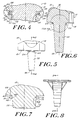
- Figure 4 is a detail view of a portion "A" of Figure 3.
- Figure 5 is a front view of a tibial bearing insert according to the present invention.
- Figure 6 is a sectional view of the tibial bearing insert of Figure 5, at line 6-6.
- Figure 7 is a detail view of portion "B" of the tibial bearing insert of Figure 6.
- Figure 8 is a front view of a tibial tray according to the present invention.
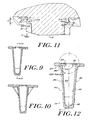
- Figure 9 is a front sectional view of the tibial tray of Figure 8, at line 9-9.
- Figure 10 is a side sectional view of the tibial tray of Figure 9, at line 10-10.
- Figure 11 is a partial sectional view of the prosthesis system of the invention in which tibial bearing insert is rotated approximately 4° relative to the tibial tray.
- Figure 12 is a side sectional view of an alternative embodiment of the invention in which tapered negative surface features are formed in the tibial tray.
- Figure 13 is a detail view of portion "C" of the tibial tray of Figure 8.
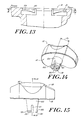
- Figure 14 is a perspective view of an alternative tibial bearing insert useful with the present invention.
- Figure 15 is a front view of the tibial bearing insert of Figure 14.
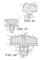
- Figure 16 is a side sectional view of the tibial bearing insert of Figure 15, at lie 16-16.
- Figure 17 is a front sectional view of a prosthesis system utilizing the tibial bearing insert of Figure 16, with the tibial bearing insert unsecured within the tibial tray.
- Figure 18 is a front sectional view of the prosthesis system of Figure 17, with the tibial bearing insert secured within the tibial tray.
- Figure 19 is a sectional view of a reinforcement pin.
- Figure 20 is a front view, with partial cutaway, of a prothesis system according to an alternative embodiment of the invention.
- Figure 21 is a detail view of Detail A of the system of Figure 20.
- Figure 22 is a top view of the prosthesis system of Figure 20 with the tibial bearing insert rotated approximately 5° with respect to the tibial tray.
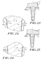
- Figure 23 is a sectional view at lines 23-23 of the prosthesis system of Figure 22.
- Figure 24 is a view of the Detail A of Figure 23.
- Figure 25 is a sectional view at lines 25-25 of the prosthesis system of Figure 22.
- Figure 26 is a view of Detail B of Figure 25.
- Figure 27 is a sectional view of an unassembled alternative prosthesis system according to the invention.
- Figure 28 is a sectional view of the prosthesis system of Figure 27 in an assembled condition.
- The invention provides a
prosthesis system 10 that has first and second components that can be axially secured to one another while maintaining the ability of one component to rotate with respect to the other. For purposes of illustration thesystem 10 is shown as the tibial component of a knee joint prosthesis. It is understood, however, that the invention is applicable to other prostheses. - Referring to Figures 1 and 2, the
system 10 includes a first component in the form of atibial tray 14, upon which is mounted a second component, i.e.,tibial bearing insert 12. The mounting of the tibial bearing insert 12 to thetibial tray 14 is such that the tibial bearing insert is able to rotate with respect to the proximal orsuperior surface 32 of the tibial tray while remaining axially secured to the tibial tray. - The tibial bearing insert 12 has an
anterior side 13, aposterior side 15, asuperior articulation surface 16 and aninferior mating surface 18. Thesuperior surface 16 may have one or morecondylar elements 20 that are adapted to articulate with complementary condyle(s) of a femoral component (not shown) of a knee joint prosthesis. Theinferior surface 18 preferably includes amating stem 22 that protrudes from theinferior mating surface 18 and that is adapted to mate selectively withtibial tray 14. - The
tibial tray 14 includes ananterior side 17, a posterior side 19, asuperior mating surface 32 and an inferiorbone contacting surface 34. Thebone contacting surface 34 has afirst portion 36 that represents an area of the inferior surface that mounts upon the proximal surface of a resected tibia (not shown). Asecond portion 38 of thebone contacting surface 34 extends from thefirst portion 36 and is adapted to extend into a cavity (not shown) formed within a patient's tibia. Preferably, thesecond portion 38 is anelongate tibial stem 39 that extends from thefirst portion 36. Thetibial stem 39 has outer side anddistal walls outer side walls 40 of thetibial stem 39 may have irregular surface features (such as steps 42) to enhance bone fixation. - The
superior surface 32 of thetibial tray 14 includes an aperture 72 (which may be of any suitable shape, e.g., substantially circular) that communicates with amating cavity 44. In an illustrated embodiment, themating cavity 44 is a blind cavity, defined byinterior side walls 45 that extend into the tibial stem. Themating cavity 44 terminates in an interiordistal wall 46 that may be substantially cone-shaped, or formed in another shape that is suitable for receiving amating stem 22. - The mating stem 22 of the
tibial bearing insert 12 is adapted to fit within themating cavity 44 of the tibial tray. A securing mechanism ensures that themating stem 22 is secured within themating cavity 44 in such a way that the tibial bearing insert is axially secured to the tibial tray. Moreover, the tibial bearing insert must be able to rotate relative to the tibial tray while the two components are secured to one another. - One of ordinary skill in the art will readily appreciate that the dimensions of
cavity 44 and mating stem 22 may vary. In one embodiment thecavity 44 has a diameter that tapers from proximal 51 to distal 53 ends thereof at an angle in the range of about 0.25° to 5°. The diameter at the proximal end 51 is in the range of about 5 to 40 mm and the diameter at thedistal end 53 is in the range of about 3 to 39 mm. Thecavity 44 preferably has a depth in the range of about 5 to 75 mm. - The mating stem 22 should have a size and shape complementary to the
cavity 44. Accordingly, the diameter ofstem 22 should taper from about 6 to 38 mm at a proximal end to about 3 to 30 mm a distal end. The length ofstem 22 preferably is in the range of about 4 to 75 mm. - The
superior surface 16 of thetibial bearing insert 12 may optionally include ablind bore 52 of the type illustrated in the embodiment of Figures 15-18. The blind bore 52 is substantially centrally located and is of a size and shape sufficient to receive areinforcement pin 54 of the type shown in Figure 19. Such reinforcement pins are well known in the art and may be substantially cylindrically shaped and made of a metal or metal alloy. Such pins may also have knurled or grooved surface features (not shown) as is known in the art. In one embodiment bore 52 is cylindrical, having a diameter of about 1 to 12 mm and a depth of about 5 to 75 mm. - As shown in Figures 1-13, the securing mechanism of the
tibial tray 14 and thetibial bearing insert 14 includes at least onenegative surface feature 24 and at least onepositive surface feature 26 which, upon engagement, form a snap fit arrangement that allows rotation of the second component with respect to the first component while axially securing the two components to each other. Preferably, the axial securement is sufficient to inhibit withdrawal of the tibial bearing insert 12 from thetibial tray 14 when a separating force, e.g., an upwardly-directed force, acts on thetibial bearing insert 12. Although the tibial bearing insert is shown to include a negative surface feature while the tibial tray includes a positive surface feature, it is understood that this arrangement can be reversed so that the positive surface feature is present on the tibial tray and the negative surface feature is present on the tibial bearing insert. - The
negative surface feature 24 may be in the form of one ormore grooves 28 formed inmating cavity 44.Grooves 28 may be formed in thecavity 44 at the proximal end 51,distal end 53, or at intermediate locations. In one embodiment,separate grooves 28 are formed on each of the anterior and posterior sides ofmating cavity 44. Eachgroove 28 is in the form of an arc that extends along a portion of the perimeter of themating cavity 44. Preferably, each groove forms an arc of about 5° to 60°. - Each
groove 28 is defined by a firstvertical surface 56, ahorizontal shoulder 58, recessedvertical surface 60 and a bottom surface 62. Thehorizontal shoulder 58 may extend from the recessedvertical surface 60 at an angle of between about 45° and 90°, and most preferably at an angle of 90°. The length (L1) ofhorizontal shoulder 58, which is the distance by which the recessedvertical surface 60 is offset from the firstvertical surface 56, should be sufficient to ensure and maintain engagement of the positive surface features 26 with thegrooves 28. Preferably, this length (L1) is about 0.25 to 3.00 mm. - One of ordinary skill in the art will appreciate the height (H) of recessed vertical ;
surface 60 may vary depending upon the requirements of a given application. In any event, this height must be sufficient to accommodate the positive surface features. As described below, the height need not be constant. Instead, the height can taper from a maximum height (Hmax) at acentral portion 30 of the groove to a minimum height (Hmin) atend portions 31 of the groove. The use of a groove having a tapered height can gradually restrict rotational movement of thetibial bearing insert 12. - As noted above, at least one
groove 28 is disposed on the tibial tray. The groove(s) may be present on any part of the tibial tray, as long as they are able to engage with a corresponding positive surface feature on the tibial bearing insert. The groove(s) preferably are located within themating cavity 44, on either theinner side walls 45 or the distal wall thereof. In an embodiment illustrated in Figures 1 to 13, the grooves are located at a proximal end ofmating cavity 44. - Although only one, continuous groove may be used, it is preferable to utilize two opposed grooves. For purposes of illustration,
grooves 28 are shown to be on opposed anterior 17 and posterior 19 sides of thetibial tray 14. It is understood, however, that opposed grooves may instead be disposed on other locations of the tibial tray, including on medial and lateral sides of the tibial tray. - One of ordinary skill in the art will readily appreciate that suitable negative surface features may include structures other than the grooves described herein.
- Positive surface features 26 include virtually any structures protruding from the tibial bearing insert 12 that are able to mate with the negative surface features 24 (e.g., grooves 28) of the
tibial tray 14 to enable the tibial bearing insert 12 to rotate with respect to thetibial tray 14 and to axially secure these components to each other. - Referring to Figures 1 to 13 the
system 10 includes at least one positive surface feature, each of which includes protruding members that are formed on a portion of the tibial bearing insert 12 such that they are able to mate with grooves. In one embodiment each positive surface feature is asnap member 64, which may be slightly deformable or deflectable, that forms an arc over a portion of the surface of thetibial bearing insert 12. Eachsnap member 64 forms an arc that is smaller than the corresponding arc ofgroove 28 with which it is to engage, in order to facilitate rotation of the tibial bearing insert 12 with respect to thetibial tray 14 when thegrooves 28 andsnap members 64 are mated. The arc formed by thesnap members 64 should be about 5° to 90° less than that ofgrooves 28. Preferably, thesnap members 64 form an arc of 4° to 85°. - For purposes of illustration, the
snap member 64 is shown to be formed on a portion of theinferior surface 18 of the tibial bearing insert 12 that is in proximity to themating cavity 44. It is understood, however, that the snap member may be disposed at alternative locations ontibial bearing insert 12. - As shown in Figures 4,7 and 11, each snap member may include a cantilevered
wall 66 that extends from thetibial bearing insert 12. Adistal end 68 of cantilevered wall extends radially outwardly fromwall 66 and has aradius wall 70 and an engagingshoulder 74. In an illustrated embodiment, the cantileveredwall 66 extends vertically downwardly frominferior surface 18 and the engagingshoulder 74 has ahorizontal surface 76 that is orthogonal to the cantileveredwall 66. The cantileveredwall 66 preferably is separated from the adjacent surface 65 of mating stem 22 by a distance of about 0.25 to 3.00 mm. - One of ordinary skill in the art will appreciate that the dimensions of snap member may vary. Generally, however, the cantilevered
wall 66 has a length of about 0.25 to 3.00 mm. Thehorizontal surface 76 of the engagingshoulder 74 preferably extends over a distance of about 0.25 to 3.00 mm. Theradius wall 70 should have sufficient curvature to promote the mating of thesnap members 84 withingroove 28. In one embodiment, theradius wall 70 has a radius in the range of about 0.10 mm to 1.00 mm. - The
system 10 is assembled by forcing the tibial bearing insert 12 within thetibial tray 14. As theradius wall 70 contacts thetibial tray 14 and as force is applied to thetibial bearing insert 14radius wall 70 slides past the firstvertical surface 56 ofgroove 28. In one embodiment, the cantileveredwall 66 of thesnap member 64 deflects by a minimal amount sufficient to accommodate the mating of the snap member and the groove. Once the snap member is fully inserted within the groove, the cantileveredwall 66 returns to its original position and thehorizontal surface 76 of the engagingshoulder 74 of the snap member abuts thehorizontal shoulder 58 of the groove, thereby providing axial securement of the tibial bearing insert 12 to thetibial tray 14. - At the same time, some degree of rotation of the tibial bearing insert with respect to the tibial tray is possible because the arc defined by the grooves is greater than the arc defined by the snap members. Preferably, the tibial bearing insert is able to rotate in the range of about 1° to 30°.
- In one embodiment, shown in Figures 12 and 13, the
grooves 28 may have a height that tapers from a maximum height (Hmax) at acentral portion 30 of thegroove 31 to a minimum height (Hmin) at end portions of the groove. By way of example, the maximum height may be about 0.25 mm and the minimum height may be about 30 mm. The use of a tapered groove can be advantageous as it allows increasing resistance to rotation, thereby gradually restricting rotation. - One of ordinary skill in the art will appreciate that each snap member should have dimensions suitable to enable it to fit snugly within
grooves 28 with substantially no axial play. The fit of the snap members within the grooves should not be so snug, however as to present excess friction upon rotation of the tibial bearing insert. If desired a seal member (not shown) may be disposed withingrooves 28 to reduce axial play and or radial movement. - It is understood that the negative and positive surface features may be disposed at any location on the
tibial bearing insert 12 andtibial tray 14 that enables these surface features to be suitably engaged with each other to properly orient the tibial bearing insert 12 with respect to thetibial tray 14. In one embodiment, at least two positive surface features are present on the tibial bearing insert, at locations opposite one another. - One of ordinary skill in the art will appreciate that the securing mechanism of the tibial tray and the tibial bearing insert (or any other joint system of the invention) may be modified by any structure that facilitates the axial securement of the tibial bearing insert to the tibial tray while preserving rotatability of the tibial bearing insert. Figures 14-18 illustrate an embodiment in which the
distal end 78 of themating stem 22 includes positive surface features in the form of expandable wedge-like elements 80, each of which is separated by aslot 81. Each wedge-like element 80 has a protrudingshoulder 82 on an exterior surface thereof. The expandable wedge-like elements 80, in cooperation withslots 81, enable the diameter of thedistal end 78 of themating stem 22 to expand from a first diameter (D1) to a second diameter (D2). The first diameter (D1), as shown in Figure 17, is insufficient to enable the protrudingshoulders 82 of the wedge-like members 80 to engage a corresponding negative surface feature (e.g., groove 84) inmating cavity 44. However expansion of themating stem 22 to the second diameter (D2), as shown in Figure 18, causes interaction between the protrudingshoulders 82 and thegroove 84 that prevents removal of the tibial bearing insert 12 from thetibial tray 14. Despite this axial securement, thetibial bearing insert 12 is still able to rotate relative to thetibial tray 14. - The expansion of the mating stem from the first diameter to the second diameter may be accomplished by the insertion of a
reinforcement pin 54 within ablind bore 52 formed in thesuperior articulation surface 16 of thetibial bearing insert 12. The mating ofpin 54 withinbore 52 causes expansion of the distal end of the mating stem from the first to the second diameter. - The
reinforcement pin 54 may be of the type described above and shown in Figure 19. The blind bore 52 is preferably located substantially centrally on thesuperior articulation surface 16 of thetibial bearing insert 12 and is of a size and shape sufficient to receive areinforcement pin 54. In one embodiment, thebore 52 is cylindrical and has a diameter of about 1 to 12 mm and a depth of about 12 to 76 mm. The reinforcement pin may have a diameter of about 1 to 10 mm and a length of about 5 to 60 mm. - Figures 14-18 illustrate four wedge-
like elements 80 formed at thedistal end 78 ofmating stem 22. It is understood, however, that an alternative number ofwedge elements 80 may be present. For example, mating stem 22 may have only two or three wedge elements, or more than four. - Alternatively, the
tibial bearing insert 12 may include wedge-like elements 80 that are biased to a first diameter that enables axial securement withtibial tray 14. Upon mating of the tibial bearing insert 12 withtibial tray 14, the wedge-like elements are compressed to a second, smaller diameter. Upon proper seating of the tibial bearing insert the wedge-like elements return to the first diameter. - The embodiment of Figures 14-18 may be further modified by omitting wedge-
like elements 80 andgroove 84. Instead axial securement can be provided by the frictional engagement of mating stem 22 with the inner wall ofmating cavity 44 whenreinforcement pin 54 is inserted intobore 52. Surface features (not shown) analogous to wedge-like elements 80 may be provided at a proximal portion of mating stem 22 to interact with complementary surface features on a top portion ofcavity 44 when thereinforcement pin 54 is inserted. The surface features on themating stem 22 can be of dimensions smaller than the surface features on thecavity 44 so as to limit the degree of rotation of thetibial bearing insert 12. - Figures 27 and 28 illustrate an alternative embodiment in which wedge-
like elements 80 are disposed at a more proximal portion ofmating stem 22. - Figures 20-26 illustrate an alternative securing mechanism for the
tibial tray 14 and the tibial bearing insert 12 that includes at least onenegative surface feature 85 and at least onepositive surface feature 87, that are matable to axially secure the tibial bearing insert 12 to thetibial tray 14 while permitting rotation of the tibial bearing insert 12 with respect to thetibial tray 14. Although the tibial tray is shown to include anegative surface feature 85 while the tibial bearing insert includes apositive surface feature 87, it is understood that this arrangement can be reversed. - The
negative surface feature 85 may be in the form of at least onecircumferential groove 90 that extends partially or entirely around the perimeter of themating cavity 44. Thecircumferential groove 90 may extend in a linear fashion about theinterior side walls 45 of fashion about the perimeter ofmating cavity 44, or it may follow another path, such as an eccentric, sinusoidal, parabolic, or wave. Further, the circumferential groove(s) may be present at any location on the tibial tray, as long as it is able to engage with a corresponding positive surface feature on thetibial bearing insert 12. The circumferential groove(s) preferably are disposed on theinner side walls 45 of themating cavity 44.Circumferential groove 90 may be located at any position between the proximal and distal ends 51, 53 ofmating cavity 44. - The dimensions of circumferential groove(s) 90 may vary within limits readily appreciated by one of ordinary skill in the art. The
circumferential groove 90 may have a substantially constant opening width (W) in the range of about 1 to 20 mm. The depth ofcircumferential groove 90 generally is in the range of 0.25 to 2.00 mm. - One of ordinary skill in the art will readily appreciate that suitable negative surface features may include structures other than the circumferential groove described herein.
-
Positive surface feature 87 also includes virtually any structure that protrudes from the tibial bearing insert 12 that is able to mate with the negative surface feature 85 (e.g., the circumferential groove 90) of thetibial tray 14 to enable the tibial bearing insert 12 to rotate with respect to thetibial tray 14 and to axially secure these components to each other. - As shown in Figures 20-26, the
positive surface feature 87 is in the form of aneccentric rib 86 that extends over a portion of the surface of thetibial bearing insert 12. The term "eccentric rib" refers to the property of therib 86 that enables it to form a substantially sinusoidal, parabolic, or wave-like path about all or part of the outer surface of mating stem 22 Preferably, the difference between high and low points in the oscillation ofrib 86 is about 1 to 10 mm. Therib 86 may extend about the circumference of themating stem 22 over a range of about 1 to 4 oscillation cycles. - The dimensions of
rib 86 may also vary and depend to a large extent on the dimensions of thecircumferential groove 90. Therib 86 must be of dimensions that enable it to fit withincircumferential groove 90 to axially secure tibial bearing insert 12 totibial tray 14. There must also exist sufficient clearance to enable some side-to-side movement of therib 86 withincircumferential groove 90 to permit some rotation of thetibial bearing insert 12. Therib 86 must also have a thickness (T) that is less than the width (W) ofcircumferential groove 90. Generally, the thickness (T) ofrib 86 ranges between about 1 and 15 mm. Theeccentric rib 86 should protrude from mating stem 22 by a distance that is less than the depthcircumferential groove 90. - The
eccentric rib 86 may be disposed at various locations ontibial bearing insert 12. Preferably, however, theeccentric rib 86 is formed on a surface ofmating stem 22. Such that it extends partially or fully about the circumference ofmating stem 22. - Upon mating of
rib 86 withincircumferential groove 90, thetibial bearing insert 12 and tibial tray are axially secured to each other. The tibial bearing insert 12 is also able to rotate with respect to thetibial tray 14. However, the degree of rotation is generally limited to about 5° to 90°. As rotation progresses thehigh point 102 and/orlow point 104 ofrib 86 impinges upon the walls of the groove, prohibiting further rotation, or greatly increasing the force necessary to effect rotation. In one embodiment, therib 86 andgroove 90 are generally of the same shape. - One of ordinary skill in the art will appreciate that the rotation of the tibial bearing insert may further be controlled by varying other dimensions of the
circumferential groove 90 and/or theeccentric rib 86, such as the length of the eccentric rib, the distance by which the eccentric rib extends into the circumferential groove, and the width of the circumferential groove. - Figures 22 through 26 illustrate the ability of
groove 90 andrib 86 to limit rotation oftibial bearing insert 12. In Figure 22, the tibial bearing insert is rotated by approximately 5°. Upon doing so, thehigh points 102 ofrib 86, as shown in Figures 23 and 24, impinge uponupper walls 106 ofgroove 90, thereby preventing further rotation, or greatly increasing the force necessary to effect further rotation. At the same time, as shown in Figures 25 and 26, thelow points 104 ofrib 86 impinge uponlower walls 108 ofgroove 90. - One of ordinary skill in the art will appreciate that the components of the
system 10 of the invention can be made from a variety of known materials. The tibial bearing insert typically is made of a polymeric material such as ultra high molecular weight polyethylene. The tibial bearing insert can be made of a variety of known metals and metal alloys that are suitable for implantable prostheses. - One of ordinary skill in the art will further appreciate that minor modifications may be made to the invention described herein without departing from its intended scope. All references noted herein are expressly incorporated by reference in their entirety.
Claims (25)
- A joint prosthesis system, comprising:a first component having a superior mounting surface and an inferior bone contacting surface, the superior mounting surface having a cavity defined by inner side and distal walls;a second component, having a superior articulation surface, an inferior mating surface and a mating stem protruding from the inferior mating surface, the mating stem including a stem mounting surface that is mountable within the cavity; anda securing mechanism comprising at least one first surface feature located on the first component and at least one second surface feature located on the second component, the at least one first surface feature being engageable with the at least one second surface feature to provide positive axial securement of the second component to the first component and to permit rotation of the second component with respect to the first component.
- The system of claim 1, wherein the at least one first surface feature comprises a negative surface feature and the at least one second surface feature comprises a positive surface feature having a predetermined width.
- The system of claim 2, wherein the at least one positive surface feature is deformable.
- The system of claim 3, wherein the at least one negative surface feature comprises a recess member that is adapted and dimensioned to engage with the at least one deformable positive surface feature in a snap fit arrangement that, upon engagement, axially secures the second component to the first component.
- The system of claim 4, wherein the at least one recess member defines an arc having a pre-determined length that is greater than the width of the at least one positive surface feature to permit rotation of the second component with respect to the first component.
- The system of claim 5, wherein the second component is permitted to rotate about ±5-90 degrees with respect to the first component.
- The system of claim 4, wherein the at least one recess member has a height that tapers from a maximum at a central portion thereof to a minimum at end portions thereof.
- The system of claim 1, wherein the at least one second surface feature is disposed on the inferior surface of the second component, adjacent a proximal portion of the mating stem mounting surface of the second component.
- The system of claim 1, wherein the at least one first surface feature is formed at a proximal end of the interior side wall of the cavity and the at least one second surface feature is formed adjacent a proximal end of the stem mounting surface of the second component.
- The system of claim 1, wherein the first component is a tibial tray and the second component is a tibial bearing insert.
- The system of claim 10, further comprising:an axial bore formed in the superior surface of the tibial bearing insert, the axial bore being defined by a bore interior side wall; anda reinforcement pin mountable within the axial bore, the reinforcement pin having a proximal end and a distal end.
- The system of claim 11, wherein the at least one first surface feature is one or more discrete negative surface features formed in the inner side wall of a distal end of the cavity and the at least one second surface feature is one or more positive surface features formed on the stem mounting surface.
- The system of claim 12, wherein the mounting surface has a diameter that is expandable between a first diameter that does not permit engagement of the one or more positive surface features with the one or more negative surface features and a second diameter that permits engagement of the one or more positive surface features with the one or more negative surface features so as to axially secure the second component to the first component.
- The system of claim 13, wherein the engagement of the distal end of the reinforcement pin with a distal end of the bore interior side wall effects the expansion of the stem mounting surface from the first diameter to the second diameter.
- The system of claim 11, wherein the axial bore has a depth in the range of about 5 to 75 mm.
- The system of claim 15, wherein the reinforcement pin has a length in the range of from about 5 to about 75 mm.
- The system of claim 1, wherein the cavity has a depth in the range of about 5 to 75 mm.
- The system of claim 1, wherein the mating stem has a length in the range of about 5 to about 75 mm.
- A knee joint prosthesis system, comprising:a tibial tray having a superior mounting surface and an inferior bone-contacting surface, the superior mounting surface having a cavity defined by inner side and distal walls;a tibial bearing insert matable to and rotatable relative to the tibial tray, the tibial bearing insert having a superior articulation surface and an inferior mating surface, the inferior mating surface including a mating stem having a stem mounting surface that is mountable within the cavity; anda securing mechanism comprising at least one first surface feature located on the inner side wall of the tibial tray and at least one second surface feature located on the tibial bearing insert, the at least one first surface feature being engageable with the at least one second surface feature to form a snap-fit arrangement that provides positive axial securement of the tibial tray and the tibial bearing insert.
- The system of claim 19, wherein the at least one first surface feature is a negative surface feature and the at least one second surface feature is a deformable positive surface feature.
- A knee joint prosthesis system, comprising:a tibial tray having a superior mounting surface and an inferior bone-contacting surface, the superior mounting surface having a cavity defined by inner side and distal walls, the superior surface of the tibial tray including an axial bore formed therein, the axial bore being defined by a bore inner side wall;a tibial bearing insert having a superior articulation surface that includes a blind bore, and an inferior surface, the inferior surface including a mating stem having a stem mounting surface that is mountable within the cavity;a reinforcement pin selectively mountable within the blind bore; anda securing mechanism comprising at least one negative surface feature located on the tibial tray and at least one positive feature located on the tibial bearing insert, the at least one negative surface feature being engageable with the at least one positive surface feature to provide positive axial securement of the second component to the first component and to permit rotation of the second component with respect to the first component.
- The system of claim 21, wherein the at least one negative surface feature is formed in the inner side wall of the cavity of the tibial tray and the at least one positive surface feature is formed on the stem mounting surface of the mating stem.
- The system of claim 22, wherein the stem mounting surface has a diameter that is expandable between a first diameter that does not permit engagement of the at least one positive surface feature with the at least one negative surface feature and a second diameter that permits engagement of the at least one positive surface feature with the at least one negative feature.
- The system of claim 23, wherein the engagement of the reinforcement pin with a distal end of the axial bore effects the expansion of the stem mounting surface from the first diameter to the second diameter.
- The system of claim 24, wherein the at least one positive surface feature is formed on a distal end of the stem mounting surface of the mating stem.
Applications Claiming Priority (2)
| Application Number | Priority Date | Filing Date | Title |
|---|---|---|---|
| US936383 | 1997-09-25 | ||
| US08/936,383 US5951603A (en) | 1997-09-25 | 1997-09-25 | Rotatable joint prosthesis with axial securement |
Publications (3)
| Publication Number | Publication Date |
|---|---|
| EP0904750A2 true EP0904750A2 (en) | 1999-03-31 |
| EP0904750A3 EP0904750A3 (en) | 2000-01-05 |
| EP0904750B1 EP0904750B1 (en) | 2006-03-08 |
Family
ID=25468556
Family Applications (1)
| Application Number | Title | Priority Date | Filing Date |
|---|---|---|---|
| EP98307772A Expired - Lifetime EP0904750B1 (en) | 1997-09-25 | 1998-09-24 | Rotatable joint prosthesis with axial securement |
Country Status (3)
| Country | Link |
|---|---|
| US (1) | US5951603A (en) |
| EP (1) | EP0904750B1 (en) |
| DE (1) | DE69833736T2 (en) |
Cited By (4)
| Publication number | Priority date | Publication date | Assignee | Title |
|---|---|---|---|---|
| DE10221272A1 (en) * | 2002-05-14 | 2003-11-27 | Peter Brehm | Tibial component and sliding plate of a knee joint endoprosthesis |
| FR2949668A1 (en) * | 2009-09-08 | 2011-03-11 | Ohst Medizintechnik Ag Et Iso | Knee prostheses for restoration of articulation between femur and tibia, has plane located at determined distance from rotation axis, and another plane forming determined non zero angle with rotation axis |
| EP2412338A1 (en) * | 2006-10-13 | 2012-02-01 | DePuy Products, Inc. | Mobile/fixed prosthetic knee systems |
| EP2774582B1 (en) * | 2013-03-07 | 2020-01-15 | DePuy Ireland Unlimited Company | Fixed-bearing knee prosthesis |
Families Citing this family (65)
| Publication number | Priority date | Publication date | Assignee | Title |
|---|---|---|---|---|
| FR2768613B1 (en) * | 1997-09-23 | 1999-12-17 | Tornier Sa | KNEE PROSTHESIS WITH ROTATABLE PLATFORM |
| US6238434B1 (en) * | 1998-08-05 | 2001-05-29 | Biomedical Engineering Trust I | Knee joint prosthesis with spinout prevention |
| US6210444B1 (en) * | 1999-10-26 | 2001-04-03 | Bristol-Myers Squibb Company | Tibial knee component with a mobile bearing |
| US6447549B1 (en) | 2000-10-06 | 2002-09-10 | Sulzer Orthopedics Inc. | Modular knee prosthesis system |
| US6558426B1 (en) | 2000-11-28 | 2003-05-06 | Medidea, Llc | Multiple-cam, posterior-stabilized knee prosthesis |
| US6569202B2 (en) * | 2001-04-02 | 2003-05-27 | Whiteside Biomechanics, Inc. | Tray and liner for joint replacement system |
| US7273499B2 (en) * | 2002-09-30 | 2007-09-25 | Depuy Products, Inc. | Modular trial mechanism |
| EP1601316A1 (en) * | 2003-02-04 | 2005-12-07 | Zimmer Austin, Inc. | Rotating/non-rotating tibia plate/insert system |
| US8388624B2 (en) | 2003-02-24 | 2013-03-05 | Arthrosurface Incorporated | Trochlear resurfacing system and method |
| US7390327B2 (en) * | 2003-10-03 | 2008-06-24 | Howmedica Osteonics Corp. | Punch apparatus and method for surgery |
| US20050246028A1 (en) * | 2004-04-28 | 2005-11-03 | Buechel-Pappas Trust | Prosthetic knee |
| WO2007053572A2 (en) * | 2005-10-31 | 2007-05-10 | Depuy Products, Inc. | Modular fixed and mobile bearing prosthesis system |
| US7691149B2 (en) * | 2006-05-15 | 2010-04-06 | Biomet Manufacturing Corp. | Porous titanium modular revision patella system |
| US20080091273A1 (en) * | 2006-10-13 | 2008-04-17 | Hazebrouck Stephen A | Mobile/fixed prosthetic knee systems |
| US20080114463A1 (en) * | 2006-10-13 | 2008-05-15 | Auger Daniel D | Mobile/fixed prosthetic knee systems |
| US20080091272A1 (en) * | 2006-10-13 | 2008-04-17 | Aram Luke J | Mobile/fixed prosthetic knee systems |
| WO2008073404A2 (en) | 2006-12-11 | 2008-06-19 | Arthrosurface Incorporated | Retrograde resection apparatus and method |
| US8562616B2 (en) | 2007-10-10 | 2013-10-22 | Biomet Manufacturing, Llc | Knee joint prosthesis system and method for implantation |
| US8157869B2 (en) | 2007-01-10 | 2012-04-17 | Biomet Manufacturing Corp. | Knee joint prosthesis system and method for implantation |
| US8328873B2 (en) | 2007-01-10 | 2012-12-11 | Biomet Manufacturing Corp. | Knee joint prosthesis system and method for implantation |
| US8187280B2 (en) | 2007-10-10 | 2012-05-29 | Biomet Manufacturing Corp. | Knee joint prosthesis system and method for implantation |
| US8163028B2 (en) | 2007-01-10 | 2012-04-24 | Biomet Manufacturing Corp. | Knee joint prosthesis system and method for implantation |
| US8632600B2 (en) | 2007-09-25 | 2014-01-21 | Depuy (Ireland) | Prosthesis with modular extensions |
| US8128703B2 (en) | 2007-09-28 | 2012-03-06 | Depuy Products, Inc. | Fixed-bearing knee prosthesis having interchangeable components |
| US9204967B2 (en) | 2007-09-28 | 2015-12-08 | Depuy (Ireland) | Fixed-bearing knee prosthesis having interchangeable components |
| US7918893B2 (en) * | 2007-09-30 | 2011-04-05 | Depuy Products, Inc. | Hinged orthopaedic prosthesis |
| US8187335B2 (en) | 2008-06-30 | 2012-05-29 | Depuy Products, Inc. | Posterior stabilized orthopaedic knee prosthesis having controlled condylar curvature |
| US8192498B2 (en) | 2008-06-30 | 2012-06-05 | Depuy Products, Inc. | Posterior cructiate-retaining orthopaedic knee prosthesis having controlled condylar curvature |
| US8206451B2 (en) | 2008-06-30 | 2012-06-26 | Depuy Products, Inc. | Posterior stabilized orthopaedic prosthesis |
| US9119723B2 (en) | 2008-06-30 | 2015-09-01 | Depuy (Ireland) | Posterior stabilized orthopaedic prosthesis assembly |
| US8828086B2 (en) | 2008-06-30 | 2014-09-09 | Depuy (Ireland) | Orthopaedic femoral component having controlled condylar curvature |
| US9168145B2 (en) | 2008-06-30 | 2015-10-27 | Depuy (Ireland) | Posterior stabilized orthopaedic knee prosthesis having controlled condylar curvature |
| US8236061B2 (en) | 2008-06-30 | 2012-08-07 | Depuy Products, Inc. | Orthopaedic knee prosthesis having controlled condylar curvature |
| US8696754B2 (en) * | 2008-09-03 | 2014-04-15 | Biomet Manufacturing, Llc | Revision patella prosthesis |
| WO2010121250A1 (en) | 2009-04-17 | 2010-10-21 | Arthrosurface Incorporated | Glenoid resurfacing system and method |
| WO2016154393A1 (en) | 2009-04-17 | 2016-09-29 | Arthrosurface Incorporated | Glenoid repair system and methods of use thereof |
| US9510949B2 (en) * | 2009-06-26 | 2016-12-06 | The Cleveland Clinic Foundation | Prosthetic joint component with rotation-regulating structure |
| US9011547B2 (en) | 2010-01-21 | 2015-04-21 | Depuy (Ireland) | Knee prosthesis system |
| WO2011109836A1 (en) | 2010-03-05 | 2011-09-09 | Arthrosurface Incorporated | Tibial resurfacing system and method |
| US8317870B2 (en) | 2010-09-30 | 2012-11-27 | Depuy Products, Inc. | Tibial component of a knee prosthesis having an angled cement pocket |
| US8287601B2 (en) | 2010-09-30 | 2012-10-16 | Depuy Products, Inc. | Femoral component of a knee prosthesis having an angled cement pocket |
| WO2013086340A1 (en) | 2011-12-09 | 2013-06-13 | Howmedica Osteonics Corp. | Surgical reaming instrument for shaping a bone cavity |
| WO2013096746A1 (en) | 2011-12-22 | 2013-06-27 | Arthrosurface Incorporated | System and method for bone fixation |
| EP2797520A1 (en) | 2011-12-30 | 2014-11-05 | Howmedica Osteonics Corp. | Systems for preparing bone voids to receive a prosthesis |
| DE112013003358T5 (en) | 2012-07-03 | 2015-03-19 | Arthrosurface, Inc. | System and procedure for joint surface replacement and repair |
| US8961612B2 (en) | 2012-08-30 | 2015-02-24 | Biomet Manufacturing, Llc | Knee component having orbital interface boss |
| US9532879B2 (en) | 2012-09-20 | 2017-01-03 | Depuy Ireland Unlimited Company | Femoral knee prosthesis system with augments and multiple lengths of sleeves sharing a common geometry |
| US9320603B2 (en) | 2012-09-20 | 2016-04-26 | Depuy (Ireland) | Surgical instrument system with multiple lengths of broaches sharing a common geometry |
| US20140081410A1 (en) * | 2012-09-20 | 2014-03-20 | Jay R. Lieberman | Modular knee prosthesis system with multiple lengths of sleeves sharing a common geometry |
| US9526513B2 (en) | 2013-03-13 | 2016-12-27 | Howmedica Osteonics Corp. | Void filling joint prosthesis and associated instruments |
| US10596009B2 (en) * | 2013-03-15 | 2020-03-24 | Smith & Nephew, Inc. | Knee augment |
| US9492200B2 (en) | 2013-04-16 | 2016-11-15 | Arthrosurface Incorporated | Suture system and method |
| US10624748B2 (en) | 2014-03-07 | 2020-04-21 | Arthrosurface Incorporated | System and method for repairing articular surfaces |
| US11607319B2 (en) | 2014-03-07 | 2023-03-21 | Arthrosurface Incorporated | System and method for repairing articular surfaces |
| US9931219B2 (en) | 2014-03-07 | 2018-04-03 | Arthrosurface Incorporated | Implant and anchor assembly |
| CN113081393A (en) * | 2014-06-18 | 2021-07-09 | 宝来瑞斯医疗有限公司 | Mitral valve implant for treating valvular regurgitation |
| US10149763B2 (en) | 2015-01-12 | 2018-12-11 | Howmedica Osteonics Corp. | Multipurpose void filling prosthesis |
| CN106880424A (en) * | 2015-12-16 | 2017-06-23 | 重庆润泽医药有限公司 | A kind of artificial shoulder joint prosthesis |
| CN106913401B (en) * | 2015-12-25 | 2019-02-19 | 重庆润泽医药有限公司 | A kind of multisection type hip joint |
| US10231840B2 (en) | 2016-07-27 | 2019-03-19 | Howmedica Osteonics Corp. | Low profile tibial baseplate with fixation members |
| CA3108761A1 (en) | 2017-08-04 | 2019-02-07 | Arthrosurface Incorporated | Multicomponent articular surface implant |
| US10736748B2 (en) | 2018-05-02 | 2020-08-11 | Depuy Ireland Unlimited Company | Orthopaedic prosthetic system for a hinged-knee prosthesis |
| US11033396B2 (en) * | 2019-02-05 | 2021-06-15 | Depuy Ireland Unlimited Company | Orthopaedic prosthetic system for a rotating hinged-knee prosthesis |
| US11116641B2 (en) | 2019-02-05 | 2021-09-14 | Depuy Ireland Unlimited Company | Orthopaedic prosthetic system for a rotating hinged-knee prosthesis |
| GB2596006B (en) | 2019-03-12 | 2022-11-30 | Arthrosurface Inc | Humeral and glenoid articular surface implant systems and methods |
Citations (6)
| Publication number | Priority date | Publication date | Assignee | Title |
|---|---|---|---|---|
| US4219893A (en) | 1977-09-01 | 1980-09-02 | United States Surgical Corporation | Prosthetic knee joint |
| US4301553A (en) | 1975-08-15 | 1981-11-24 | United States Surgical Corporation | Prosthetic knee joint |
| US5059216A (en) | 1989-09-29 | 1991-10-22 | Winters Thomas F | Knee joint replacement apparatus |
| US5071438A (en) | 1990-11-07 | 1991-12-10 | Intermedics Orthopedics, Inc. | Tibial prothesis with pivoting articulating surface |
| US5171283A (en) | 1989-07-11 | 1992-12-15 | Biomedical Engineering Trust | Compound shape rotating bearing |
| US5489311A (en) | 1994-01-21 | 1996-02-06 | Joint Medical Products Corporation | Prosthesis with orientable bearing surface |
Family Cites Families (35)
| Publication number | Priority date | Publication date | Assignee | Title |
|---|---|---|---|---|
| US4136405A (en) * | 1977-04-29 | 1979-01-30 | Zimmer U.S.A. | Rotational offset knee prosthesis |
| DE2965891D1 (en) * | 1978-03-10 | 1983-08-25 | Biomedical Eng Corp | Improved joint endoprosthesis |
| US4470158A (en) * | 1978-03-10 | 1984-09-11 | Biomedical Engineering Corp. | Joint endoprosthesis |
| EP0046926B1 (en) * | 1980-09-03 | 1985-12-11 | Waldemar Link (GmbH & Co.) | Knee joint endoprosthesis |
| DE3119841A1 (en) * | 1981-05-19 | 1982-12-16 | GMT GESELLSCHAFT FüR MEDIZINISCHE TECHNIK MBH | ENDOPROTHESIS OF A KNEE JOINT |
| DE3136636A1 (en) * | 1981-09-16 | 1983-03-31 | Waldemar Link (Gmbh & Co), 2000 Hamburg | Tibial plateau made of plastic with a baseplate of hard material |
| DE3138848A1 (en) * | 1981-09-30 | 1983-04-21 | GMT GESELLSCHAFT FüR MEDIZINISCHE TECHNIK MBH | ENDOPROTHESIS TO REPLACE ROD-SHAPED BONES |
| DE3431645A1 (en) * | 1984-08-29 | 1986-03-13 | GMT GESELLSCHAFT FüR MEDIZINISCHE TECHNIK MBH | ENDOPROTHESIS |
| SE450460B (en) * | 1984-11-28 | 1987-06-29 | Albrektsson Bjoern | DEVICE IN ARTIFICIAL MENISH FOR A KNEE JOINT PROTECTION |
| GB8432267D0 (en) * | 1984-12-20 | 1985-01-30 | Thackray C F Ltd | Knee prosthesis |
| FR2601873B1 (en) * | 1986-07-25 | 1994-07-01 | Cuilleron J | TOTAL INTRACONDYLIAN KNEE PROSTHESIS |
| US4888021A (en) * | 1988-02-02 | 1989-12-19 | Joint Medical Products Corporation | Knee and patellar prosthesis |
| US5011496A (en) * | 1988-02-02 | 1991-04-30 | Joint Medical Products Corporation | Prosthetic joint |
| FR2631814A1 (en) * | 1988-05-31 | 1989-12-01 | Scernp | SLIDING KNEE PROSTHESIS |
| GB9005496D0 (en) * | 1990-03-12 | 1990-05-09 | Howmedica | Tibial component for a replacement knee prosthesis and total knee prosthesis incorporating such a component |
| US5370701A (en) * | 1990-09-28 | 1994-12-06 | Arch Development Corporation | Rotating/sliding contrained prosthetic knee |
| DE69128961T2 (en) * | 1990-11-14 | 1998-10-08 | Arch Dev Corp | IMPROVED KNEE PROSTHESIS WITH MOVABLE BEARING |
| GB9102348D0 (en) * | 1991-02-04 | 1991-03-20 | Inst Of Orthopaedics The | Prosthesis for knee replacement |
| ATE205377T1 (en) * | 1991-06-17 | 2001-09-15 | Andre Baehler | JOINT PROSTHESIS, IN PARTICULAR KNEE JOINT PROSTHESIS |
| US5395401A (en) * | 1991-06-17 | 1995-03-07 | Bahler; Andre | Prosthetic device for a complex joint |
| US5282868A (en) * | 1991-06-17 | 1994-02-01 | Andre Bahler | Prosthetic arrangement for a complex joint, especially knee joint |
| DE4128171C1 (en) * | 1991-08-24 | 1993-04-01 | Aesculap Ag, 7200 Tuttlingen, De | |
| ATE176145T1 (en) * | 1992-01-14 | 1999-02-15 | Sulzer Orthopaedie Ag | MENISCUS PLATFORM FOR ARTIFICIAL KNEE JOINT |
| NZ243181A (en) * | 1992-04-23 | 1994-10-26 | Michael John Pappas | Prosthetic joint with guide means to limit articulation of a first element and bearing means to two degrees of freedom |
| DE9212879U1 (en) * | 1992-09-24 | 1994-01-27 | Link Waldemar Gmbh Co | Knee joint endoprosthesis to replace the shin joint surfaces |
| US5370699A (en) * | 1993-01-21 | 1994-12-06 | Orthomet, Inc. | Modular knee joint prosthesis |
| EP0627202B1 (en) * | 1993-04-05 | 1998-06-24 | Procom S.A. | Prosthetic assembly for forming a knee joint |
| IT1264820B1 (en) * | 1993-07-28 | 1996-10-10 | Cremascoli G Srl | TOTAL KNEE PROSTHESIS TOTAL KNEE PROSTHESIS |
| DE4409787A1 (en) * | 1994-03-22 | 1995-09-28 | Alphanorm Medizintechnik Gmbh | Knee prosthesis |
| FR2719466B1 (en) * | 1994-05-04 | 1997-06-06 | Ysebaert Sa | Knee prosthesis with movable meniscus. |
| FR2721820B1 (en) * | 1994-06-30 | 1996-12-13 | Ysebaert Sa | KNEE PROSTHETIC JOINT, IN PARTICULAR ONE-COMPARTMENTAL KNEE PROSTHESIS, OR JOINT PROSTHESIS |
| GB9415180D0 (en) * | 1994-07-28 | 1994-09-21 | Walker Peter S | Stabilised mobile bearing knee |
| FR2726174B1 (en) * | 1994-10-26 | 1997-04-04 | Cornic Michel | KNEE JOINT PROSTHESIS |
| FR2728782B1 (en) * | 1994-12-30 | 1998-10-16 | Jbs Sa | KNEE PROSTHESIS |
| US5683468A (en) * | 1995-03-13 | 1997-11-04 | Pappas; Michael J. | Mobile bearing total joint replacement |
-
1997
- 1997-09-25 US US08/936,383 patent/US5951603A/en not_active Expired - Lifetime
-
1998
- 1998-09-24 EP EP98307772A patent/EP0904750B1/en not_active Expired - Lifetime
- 1998-09-24 DE DE69833736T patent/DE69833736T2/en not_active Expired - Lifetime
Patent Citations (6)
| Publication number | Priority date | Publication date | Assignee | Title |
|---|---|---|---|---|
| US4301553A (en) | 1975-08-15 | 1981-11-24 | United States Surgical Corporation | Prosthetic knee joint |
| US4219893A (en) | 1977-09-01 | 1980-09-02 | United States Surgical Corporation | Prosthetic knee joint |
| US5171283A (en) | 1989-07-11 | 1992-12-15 | Biomedical Engineering Trust | Compound shape rotating bearing |
| US5059216A (en) | 1989-09-29 | 1991-10-22 | Winters Thomas F | Knee joint replacement apparatus |
| US5071438A (en) | 1990-11-07 | 1991-12-10 | Intermedics Orthopedics, Inc. | Tibial prothesis with pivoting articulating surface |
| US5489311A (en) | 1994-01-21 | 1996-02-06 | Joint Medical Products Corporation | Prosthesis with orientable bearing surface |
Cited By (4)
| Publication number | Priority date | Publication date | Assignee | Title |
|---|---|---|---|---|
| DE10221272A1 (en) * | 2002-05-14 | 2003-11-27 | Peter Brehm | Tibial component and sliding plate of a knee joint endoprosthesis |
| EP2412338A1 (en) * | 2006-10-13 | 2012-02-01 | DePuy Products, Inc. | Mobile/fixed prosthetic knee systems |
| FR2949668A1 (en) * | 2009-09-08 | 2011-03-11 | Ohst Medizintechnik Ag Et Iso | Knee prostheses for restoration of articulation between femur and tibia, has plane located at determined distance from rotation axis, and another plane forming determined non zero angle with rotation axis |
| EP2774582B1 (en) * | 2013-03-07 | 2020-01-15 | DePuy Ireland Unlimited Company | Fixed-bearing knee prosthesis |
Also Published As
| Publication number | Publication date |
|---|---|
| DE69833736D1 (en) | 2006-05-04 |
| EP0904750A3 (en) | 2000-01-05 |
| EP0904750B1 (en) | 2006-03-08 |
| DE69833736T2 (en) | 2006-11-16 |
| US5951603A (en) | 1999-09-14 |
Similar Documents
| Publication | Publication Date | Title |
|---|---|---|
| US5951603A (en) | Rotatable joint prosthesis with axial securement | |
| US6053945A (en) | Joint prosthesis having controlled rotation | |
| US6080195A (en) | Rotatable and translatable joint prosthesis with posterior stabilization | |
| US6010534A (en) | Rotatable tibial prosthesis with keyed axial securement | |
| US6306172B1 (en) | Modular tibial insert for prosthesis system | |
| US6709461B2 (en) | Modular joint prosthesis system | |
| EP1333785B1 (en) | Floating bearing knee joint prosthesis with a fixed tibial post | |
| US5766255A (en) | Modular joint prosthesis stabilization and augmentation system | |
| AU707380B2 (en) | Femoral component condyle design for knee prosthesis | |
| CA2187033C (en) | Stabilized prosthetic knee | |
| US4257129A (en) | Prosthetic knee joint tibial implant | |
| US6506215B1 (en) | Synthetic knee system | |
| US5571194A (en) | Femoral augmentation system for artificial knee joint | |
| US6800094B2 (en) | Mobile bearing patellar prosthesis with orbital translation | |
| EP0732091A2 (en) | Mobile bearing total joint replacement | |
| EP1591083A1 (en) | Prosthetic knee | |
| EP4023193B1 (en) | Cementless screw-in-peg fixation |
Legal Events
| Date | Code | Title | Description |
|---|---|---|---|
| PUAI | Public reference made under article 153(3) epc to a published international application that has entered the european phase |
Free format text: ORIGINAL CODE: 0009012 |
|
| AK | Designated contracting states |
Kind code of ref document: A2 Designated state(s): DE GB |
|
| AX | Request for extension of the european patent |
Free format text: AL;LT;LV;MK;RO;SI |
|
| PUAL | Search report despatched |
Free format text: ORIGINAL CODE: 0009013 |
|
| AK | Designated contracting states |
Kind code of ref document: A3 Designated state(s): AT BE CH CY DE DK ES FI FR GB GR IE IT LI LU MC NL PT SE |
|
| AX | Request for extension of the european patent |
Free format text: AL;LT;LV;MK;RO;SI |
|
| 17P | Request for examination filed |
Effective date: 20000613 |
|
| AKX | Designation fees paid |
Free format text: DE GB |
|
| 17Q | First examination report despatched |
Effective date: 20021028 |
|
| RAP1 | Party data changed (applicant data changed or rights of an application transferred) |
Owner name: DEPUY PRODUCTS, INC. |
|
| RAP1 | Party data changed (applicant data changed or rights of an application transferred) |
Owner name: DEPUY PRODUCTS, INC. |
|
| GRAP | Despatch of communication of intention to grant a patent |
Free format text: ORIGINAL CODE: EPIDOSNIGR1 |
|
| GRAS | Grant fee paid |
Free format text: ORIGINAL CODE: EPIDOSNIGR3 |
|
| GRAA | (expected) grant |
Free format text: ORIGINAL CODE: 0009210 |
|
| AK | Designated contracting states |
Kind code of ref document: B1 Designated state(s): DE GB |
|
| REG | Reference to a national code |
Ref country code: GB Ref legal event code: FG4D |
|
| REF | Corresponds to: |
Ref document number: 69833736 Country of ref document: DE Date of ref document: 20060504 Kind code of ref document: P |
|
| PLBE | No opposition filed within time limit |
Free format text: ORIGINAL CODE: 0009261 |
|
| STAA | Information on the status of an ep patent application or granted ep patent |
Free format text: STATUS: NO OPPOSITION FILED WITHIN TIME LIMIT |
|
| 26N | No opposition filed |
Effective date: 20061211 |
|
| PGFP | Annual fee paid to national office [announced via postgrant information from national office to epo] |
Ref country code: DE Payment date: 20130918 Year of fee payment: 16 |
|
| PGFP | Annual fee paid to national office [announced via postgrant information from national office to epo] |
Ref country code: GB Payment date: 20130918 Year of fee payment: 16 |
|
| REG | Reference to a national code |
Ref country code: DE Ref legal event code: R119 Ref document number: 69833736 Country of ref document: DE |
|
| GBPC | Gb: european patent ceased through non-payment of renewal fee |
Effective date: 20140924 |
|
| PG25 | Lapsed in a contracting state [announced via postgrant information from national office to epo] |
Ref country code: DE Free format text: LAPSE BECAUSE OF NON-PAYMENT OF DUE FEES Effective date: 20150401 Ref country code: GB Free format text: LAPSE BECAUSE OF NON-PAYMENT OF DUE FEES Effective date: 20140924 |