EP0905656A2 - Electronic monitoring device and monitoring system including same - Google Patents
Electronic monitoring device and monitoring system including same Download PDFInfo
- Publication number
- EP0905656A2 EP0905656A2 EP98305928A EP98305928A EP0905656A2 EP 0905656 A2 EP0905656 A2 EP 0905656A2 EP 98305928 A EP98305928 A EP 98305928A EP 98305928 A EP98305928 A EP 98305928A EP 0905656 A2 EP0905656 A2 EP 0905656A2
- Authority
- EP
- European Patent Office
- Prior art keywords
- subject
- closure member
- monitoring device
- electronic
- identification number
- Prior art date
- Legal status (The legal status is an assumption and is not a legal conclusion. Google has not performed a legal analysis and makes no representation as to the accuracy of the status listed.)
- Granted
Links
Images


Classifications
-
- G—PHYSICS
- G07—CHECKING-DEVICES
- G07C—TIME OR ATTENDANCE REGISTERS; REGISTERING OR INDICATING THE WORKING OF MACHINES; GENERATING RANDOM NUMBERS; VOTING OR LOTTERY APPARATUS; ARRANGEMENTS, SYSTEMS OR APPARATUS FOR CHECKING NOT PROVIDED FOR ELSEWHERE
- G07C9/00—Individual registration on entry or exit
- G07C9/20—Individual registration on entry or exit involving the use of a pass
- G07C9/28—Individual registration on entry or exit involving the use of a pass the pass enabling tracking or indicating presence
Definitions
- the present invention relates to electronic monitoring devices, and particularly to such devices to be attached to a person for monitoring the movements or other activities of the person.
- the invention also relates to an electronic monitoring system including such devices.
- Such electronic monitoring devices typically include sensors for sensing tampering with the device or removal of the device from the person to whom the device was attached, and for producing a corresponding tamper signal which is processed by a data processor and which is fed, with an identification signal identifying the respective device, to a transmitter for transmission to an external receiver.
- the external receiver may be a stationary one or a mobile one. Frequently, the receiver is a local one located in the immediate area of the confinement and transmits its information to a central station which monitors the activities of many persons having electronic monitoring devices attached to them.
- the foregoing sensors are tested periodically at relatively short sampling periods, e.g., three seconds to assure quick detection of any attempt to tamper with the monitoring device.
- sampling periods e.g., three seconds
- it l may be possible for a subject to quickly remove the monitoring device from the subject's body, and reattach it to another body, e.g., a baby, by the use of another closure member (e.g., a stolen one), thereby leaving the subject free to commit offenses without detection.
- the subject could remove the monitoring device and, using another closure member, reattach the monitoring device to himself, or to another, before re-entering a monitored area, , and thereby escape detection should the subject commit an offense.
- An object of the present invention is to provide an electronic monitoring device having protection against the possibility that such a tampering or removal of the device will go undetected.
- an electronic monitoring device to be attached to a subject for monitoring, at a remote location, movements and/or other activities of the subject, comprising: a housing attachable to the subject, and a closure member to secure the housing to the subject; the housing including electronic circuitry for receiving, processing, and transmitting to the remote location, data regarding the activities of the subject; the closure member including an identification tag having a unique identification number stored therein; the electronic circuitry including a data processor programmed to read and store the identification number from the tag when the closure member is applied to secure the housing to the subject, and periodically thereafter, to read the identification number of the closure member in the monitoring device attached to the subject, and to make a determination of whether a change has occurred between the read identification number and the stored identification number, and to transmit to the remote location an identification signal corresponding to such determination.
- Electronic identification tags having a unique identification number coded therein are known guaranteeing that no two identification tags will be alike. Incorporating such an electronic identification tag in the closure member provides assurance that if one closure member is broken, any attempt to replace it by another closure member will be detected since the two closure members would be identified by different identification numbers in their respective electronic identification tags.
- the housing is attachable to the subject by straps to enclose a limb of the subject and having ends securable together by the closure member according to the size of the limb.
- the closure member includes two parts to be disposed on the opposite sides of the strap ends to be secured together, and the identification tag is a solid state electrical device located between the parts of the closure member when so secured together.
- the identification tag is carried by the inner face of one of the parts of the closure member.
- the identification tag includes electrical connector elements brought into electrical communication (e.g., via direct contact, induction, etc.) with electrical connector elements on one of the strap ends when the closure member secures the strap ends together.
- At least one part of the closure member also has connector elements which are brought into electrical communication with the connector elements on one of the strap ends when the closure member secures the strap ends together.
- the data processor is programmed to make determinations of whether the identification number has been changed, during relatively short sampling periods, e.g., of a few seconds; to store the results of the determination; and to transmit the results at the end of transmission periods.
- the sampling periods are each 5-seconds
- transmission periods are: (a) in the order of seconds (e.g., 20-seconds) if the determination is positive, that there was a change in the identification number; (b) in the order of minutes (e.g., 5-minutes) if the determination is negative, namely that there was no change in the identification number from the last sample, and a predetermined time period (e.g., a week) has not elapsed since the time the identification number was stored; and (c) in the order of an hour if the determination is negative, namely that there was no change in the identification number, and the latter predetermined time period (e.g., a week) has elapsed since the time the identification number was stored.
- the forgoing transmission periods apply only to the transmission of the identifcation information, and that the other transmissions, e.g. tampering, body proximity, etc., continue at their normal intervals, e.g., 20-second intervals.
- Fig. 1 illustrates an electronic monitoring device, generally designated 2, to be attached to a person for monitoring movements and other activities of the person. These activities as detected by monitoring device 2 are transmitted to a local receiver 3 located in the general area of the person being monitored, such as the person's home residence. The information received by the local receiver 3 is in turn transmitted to a remote monitor 4 which monitors the activities of a number of persons each equipped with a personal monitoring device 2.
- the transmission from the monitoring device 2 to the local receiver 3 is by wireless transmission; the transmission from local receiver 3 to the remote monitor 4 may be by wireless transmission or by wires, e.g., via the regular telephone or a cellular telephone.
- Electronic monitoring device 2 includes a housing 10 for housing the electronic circuitry, and a pair of straps 11, 12 defining a band for attaching the housing to a limb, preferably the ankle or wrist of the person to be monitored.
- both straps 11 and 12 are provided with a plurality of pairs of holes 11a, 12a along their lengths, cooperable with a closure member 13 for fixing the effective lengths of the two straps according to the size of the person's ankle or wrist.
- Closure member 13 includes two parts 13a, 13b to be disposed on the opposite sides of the overlapping ends of the two straps 11, 12 after the monitoring device has been applied to the person.
- Part 13a includes four pins 14, and part 13b includes four complementary sockets 15, such that after the ends of the two straps 11, 12 have been applied around the person's ankle (or wrist), pins 14 of part 13a may be passed through the appropriate aligned holes 11a, 12a, of the overlapping ends of the two straps 11, 12, and force-fitted into their respective sockets 15 of part 13b, to fix the monitoring device to the person's ankle (or wrist).
- the illustrated monitoring device 2 further includes a tamper sensor for sensing any tampering with the monitoring devices or its removal from the person to whom it was attached.
- the tamper sensor in the illustrated monitoring device may be the same as described in the above-cited US Patent 5,504,474.
- Such a sensor includes electrical conductors (not shown) extending through the two straps 11, 12, electrical terminals 16 provided in the end of strap 12, and electrical pads 17 formed in part 13a engageable by terminals 16 when the two parts 13a, 13b of the closure member 13 are fixed as required to the overlapping ends of the two straps.
- the arrangement is that any cutting of strap 11 or 12, or any attempt to separate the two parts 13a, 13b from the straps, will result in a break in the continuity of the electrical circuit which would be sensed by the electrical circuitry within housing 10.
- an electronic identification tag is provided between the two parts 13a, 13b, of the closure member 13, before the two parts are attached together with the ends of the straps 11, 12, in between.
- the electronic identification tag 20 may be inserted between the two parts 13a, 13b before they are attached together, but preferably is included in one of the parts, in this case on its inner face of part 13a before the two parts are attached together with the ends of the straps in between.
- Electronic identification tag 20 is a solid-state semi-conductor chip having a unique identification code therein. It includes electrical connector terminals, shown at 21 and 22, which are brought into electrical contact with the electrical connector elements 16, 17, on the step end and closure member part 13a, respectively, enabling the unique identification code therein to be read by the electronic circuitry within housing 10.
- a preferred electronic identification device that may be used is Silicon Serial No. DS2401 supplied by Dallas Semiconductor Corporation. This device is a factory-lasered, 64-bit ROM that includes a unique 48-bit serial number, an 8-bit CRC (Cyclic Redundancy Check), and an 8-bit family code (01h); data is transferred serially via a 1-wire protocol which requires only a single data lead and a ground return,
- the electronic circuitry within housing 10 includes an electronic data microprocessor 30 and a transmitter 31, as shown in Fig. 2, for receiving, processing and transmitting, via antenna 32, data regarding the movements and other activities of the subject to which the monitoring device 10 is attached. As shown in Fig. 1, this data is transmitted in a wireless manner first to the local receiver 3 located in the general area of the subject being monitored, and the local receiver in turn transmits this data, by wireless or wired transmission, to the remote monitor 4 serving as a central station for monitoring the activities of many subjects.
- the inputs to the microprocessor 30 includes an open-closure sensor 33 to detect the opening or breakage of closure member 13 (or the cutting of the straps 11, 12), and a body (proximity) sensor 34 to detect removal of the monitoring device from against the subject's skin, as described for example in the above-cited US Patent 5,504,474.
- Fig. 2 also illustrates the battery power supply 35 for powering the electronic circuitry.
- Fig. 2 further illustrates the electronic identification tag 20 whose unique identification number stored therein is also inputted into the microprocessor 30.
- This identification number is read into the microprocessor when the closure member is applied to secure the ends of the straps 11, 12 to the subject, and is stored in its memory 36.
- microprocessor 30 reads the identification number of the closure member attached to it, compares the so-read identification number with that stored in memory 36, makes a determination whether a change has occurred between the read identification number and the stored one, and transmits an identification signal corresponding to such determination.
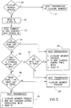
- Fig. 3 illustrates a flowchart of a preferred algorithm for operating the microprocessor 30 in order to provide notice to the remote location of an attempt to remove the monitoring device from a subject, or a change in the identification number of the closure member used in the monitoring device, with reasonable immediacy and with a minimum drain on the battery power supply 35.
- the identification information transmitting period during the first week of use of the monitoring device is somewhat different from subsequent periods.
- a check is made, via open-closure sensor 33, whether the closure member is applied (block 40). Such checks could be made every 3-seconds, for example, stored, and transmitted at transmission intervals of 20-seconds. If a closure member is not detected, the next transmission (e.g., 20-seconds later) would indicate this (block 41). If a closure member is detected, the identification number stored in its electronic tag 20 is merely read by the microprocessor 30 and stored in its memory 36.
- the identification of the current closure member is read and compared with the stored identification number (block 43). A determination is made as to whether the current identification number was changed during the last transmission (block 44). If yes, the next 20-second transmission will include the facts (1) that a closure member was present, (2), that the closure member was changed during the preceding week, and (3) the identification of the current closure member (block 45).
- the frequency of transmission of the identification information will be changed from 5 minutes to one hour (block 48), and the transmission will include the information of block 49.
- the next transmission includes only the fact that a closure member was present (block 50).
- the identification number tag could be other than electronic, e.g., optical, and fed to the data processor optically, by induction, etc.
- the monitoring device may be used for monitoring movements other than those under house arrest, e.g., movements of medical patients, children in shopping centers, animals, etc.
- the identification number tag could be concealed and/or applied to e.g., the strap itself; and the monitoring device could be applied to parts of a subject other than the limbs, e.g., around the neck or attached to subject's clothing.
Abstract
Description
- The present invention relates to electronic monitoring devices, and particularly to such devices to be attached to a person for monitoring the movements or other activities of the person. The invention also relates to an electronic monitoring system including such devices.
- As pointed out in Patent 5,504,474, incorporated herein by reference and assigned to the same assignee as the present application, the increasing overcrowding of jails and houses of detention has increased the popularity to sentence certain types of offenders, particularly non-violent ones, to confinement within a pre-designated location, such as the offender's place of residence, the residence of a responsible relative, or the location of certain rehabilitating institutions. For this purpose, a number of electronic monitoring devices have been developed to be attached to a person for monitoring the movements or other activities of the person. Such electronic monitoring devices typically include sensors for sensing tampering with the device or removal of the device from the person to whom the device was attached, and for producing a corresponding tamper signal which is processed by a data processor and which is fed, with an identification signal identifying the respective device, to a transmitter for transmission to an external receiver. The external receiver may be a stationary one or a mobile one. Frequently, the receiver is a local one located in the immediate area of the confinement and transmits its information to a central station which monitors the activities of many persons having electronic monitoring devices attached to them.
- The above-cited US Patent 5,504,474 cites a large number of prior patents, which are also hereby incorporated by reference, relating to electronic monitoring devices and electronic monitoring systems of the foregoing type.
- It will be seen that the effectiveness of such an electronic monitoring device depends to a great extent on the assurance that the device has not been removed from the subject or tampered with. The above-cited US Patent 5,504,474, and the large number of patents cited therein, disclose various types of arrangements for providing this assurance. Generally, the known arrangements include sensors which sense whether the device is against the subject's skin as it should be, whether the strap attaching the device to the subject's wrist or ankle has been cut, and/or whether the closure member, which secures the strap ends to the subject's wrist or ankle, has been broken.
- The foregoing sensors are tested periodically at relatively short sampling periods, e.g., three seconds to assure quick detection of any attempt to tamper with the monitoring device. However, particularly where longer sampling periods are used, e.g., to save power, it l may be possible for a subject to quickly remove the monitoring device from the subject's body, and reattach it to another body, e.g., a baby, by the use of another closure member (e.g., a stolen one), thereby leaving the subject free to commit offenses without detection.
- Also, it is possible that when the subject is outside a monitoring range during a non-monitored period (which may be permitted), the subject could remove the monitoring device and, using another closure member, reattach the monitoring device to himself, or to another, before re-entering a monitored area, , and thereby escape detection should the subject commit an offense.
- An object of the present invention is to provide an electronic monitoring device having protection against the possibility that such a tampering or removal of the device will go undetected.
- According to a broad aspect of the present invention, there is provided an electronic monitoring device to be attached to a subject for monitoring, at a remote location, movements and/or other activities of the subject, comprising: a housing attachable to the subject, and a closure member to secure the housing to the subject; the housing including electronic circuitry for receiving, processing, and transmitting to the remote location, data regarding the activities of the subject; the closure member including an identification tag having a unique identification number stored therein; the electronic circuitry including a data processor programmed to read and store the identification number from the tag when the closure member is applied to secure the housing to the subject, and periodically thereafter, to read the identification number of the closure member in the monitoring device attached to the subject, and to make a determination of whether a change has occurred between the read identification number and the stored identification number, and to transmit to the remote location an identification signal corresponding to such determination.
- Electronic identification tags having a unique identification number coded therein are known guaranteeing that no two identification tags will be alike. Incorporating such an electronic identification tag in the closure member provides assurance that if one closure member is broken, any attempt to replace it by another closure member will be detected since the two closure members would be identified by different identification numbers in their respective electronic identification tags.
- According to further features in the described preferred embodiment, the housing is attachable to the subject by straps to enclose a limb of the subject and having ends securable together by the closure member according to the size of the limb. The closure member includes two parts to be disposed on the opposite sides of the strap ends to be secured together, and the identification tag is a solid state electrical device located between the parts of the closure member when so secured together.
- According to still further preferred features, the identification tag is carried by the inner face of one of the parts of the closure member. In addition, the identification tag includes electrical connector elements brought into electrical communication (e.g., via direct contact, induction, etc.) with electrical connector elements on one of the strap ends when the closure member secures the strap ends together. At least one part of the closure member also has connector elements which are brought into electrical communication with the connector elements on one of the strap ends when the closure member secures the strap ends together.
- According to still further features in the described preferred embodiment, the data processor is programmed to make determinations of whether the identification number has been changed, during relatively short sampling periods, e.g., of a few seconds; to store the results of the determination; and to transmit the results at the end of transmission periods. More particularly, in the described preferred embodiment, the sampling periods are each 5-seconds, and transmission periods are: (a) in the order of seconds (e.g., 20-seconds) if the determination is positive, that there was a change in the identification number; (b) in the order of minutes (e.g., 5-minutes) if the determination is negative, namely that there was no change in the identification number from the last sample, and a predetermined time period (e.g., a week) has not elapsed since the time the identification number was stored; and (c) in the order of an hour if the determination is negative, namely that there was no change in the identification number, and the latter predetermined time period (e.g., a week) has elapsed since the time the identification number was stored.
- It will be appreciated that the forgoing transmission periods apply only to the transmission of the identifcation information, and that the other transmissions, e.g. tampering, body proximity, etc., continue at their normal intervals, e.g., 20-second intervals.
- It has been found that such an arrangement provides the required notice to the remote location with the immediacy needed for the particular situation, but with a minimum drain of power from the battery supplying the monitoring device, thereby extending the useful life of the battery before recharging or replacing.
- Further features and advantages of the invention will be apparent from the description below.
- The Invention is herein described, by way of example only, with reference to the accompanying drawings, wherein:
- Fig. 1 illustrates one form of electronic monitoring device constructed in accordance with the present invention and the monitoring system with which the device is used;
- Fig. 2 is a block diagram of the electronic system used in the electronic monitoring device of Fig. 1; and
- Fig. 3 is a flowchart illustrating a preferred operation of the microprocessor in the electron monitoring device of Figs. 1 and 2.
-
- Fig. 1 illustrates an electronic monitoring device, generally designated 2, to be attached to a person for monitoring movements and other activities of the person. These activities as detected by monitoring
device 2 are transmitted to alocal receiver 3 located in the general area of the person being monitored, such as the person's home residence. The information received by thelocal receiver 3 is in turn transmitted to aremote monitor 4 which monitors the activities of a number of persons each equipped with apersonal monitoring device 2. The transmission from themonitoring device 2 to thelocal receiver 3 is by wireless transmission; the transmission fromlocal receiver 3 to theremote monitor 4 may be by wireless transmission or by wires, e.g., via the regular telephone or a cellular telephone. -
Electronic monitoring device 2 includes ahousing 10 for housing the electronic circuitry, and a pair ofstraps straps closure member 13 for fixing the effective lengths of the two straps according to the size of the person's ankle or wrist. Closuremember 13 includes two parts 13a, 13b to be disposed on the opposite sides of the overlapping ends of the twostraps pins 14, and part 13b includes fourcomplementary sockets 15, such that after the ends of the twostraps pins 14 of part 13a may be passed through the appropriate aligned holes 11a, 12a, of the overlapping ends of the twostraps respective sockets 15 of part 13b, to fix the monitoring device to the person's ankle (or wrist). - The illustrated
monitoring device 2 further includes a tamper sensor for sensing any tampering with the monitoring devices or its removal from the person to whom it was attached. The tamper sensor in the illustrated monitoring device may be the same as described in the above-cited US Patent 5,504,474. Such a sensor includes electrical conductors (not shown) extending through the twostraps electrical terminals 16 provided in the end ofstrap 12, andelectrical pads 17 formed in part 13a engageable byterminals 16 when the two parts 13a, 13b of theclosure member 13 are fixed as required to the overlapping ends of the two straps. The arrangement is that any cutting ofstrap housing 10. - Further details of the construction of the tamper sensor, the
straps part closure member 13, are set forth in the above-cited US Patent 5,504,474, whose contents are incorporated by reference. - According to the present invention, an electronic identification tag, generally designated 20 in Fig. 1, is provided between the two parts 13a, 13b, of the
closure member 13, before the two parts are attached together with the ends of thestraps electronic identification tag 20 may be inserted between the two parts 13a, 13b before they are attached together, but preferably is included in one of the parts, in this case on its inner face of part 13a before the two parts are attached together with the ends of the straps in between. -
Electronic identification tag 20 is a solid-state semi-conductor chip having a unique identification code therein. It includes electrical connector terminals, shown at 21 and 22, which are brought into electrical contact with theelectrical connector elements housing 10. - A preferred electronic identification device that may be used is Silicon Serial No. DS2401 supplied by Dallas Semiconductor Corporation. This device is a factory-lasered, 64-bit ROM that includes a unique 48-bit serial number, an 8-bit CRC (Cyclic Redundancy Check), and an 8-bit family code (01h); data is transferred serially via a 1-wire protocol which requires only a single data lead and a ground return,
- The electronic circuitry within
housing 10 includes anelectronic data microprocessor 30 and atransmitter 31, as shown in Fig. 2, for receiving, processing and transmitting, viaantenna 32, data regarding the movements and other activities of the subject to which themonitoring device 10 is attached. As shown in Fig. 1, this data is transmitted in a wireless manner first to thelocal receiver 3 located in the general area of the subject being monitored, and the local receiver in turn transmits this data, by wireless or wired transmission, to theremote monitor 4 serving as a central station for monitoring the activities of many subjects. - Thus, as shown in Fig. 2, the inputs to the
microprocessor 30 includes an open-closure sensor 33 to detect the opening or breakage of closure member 13 (or the cutting of thestraps 11, 12), and a body (proximity)sensor 34 to detect removal of the monitoring device from against the subject's skin, as described for example in the above-cited US Patent 5,504,474. Fig. 2 also illustrates thebattery power supply 35 for powering the electronic circuitry. - Fig. 2 further illustrates the
electronic identification tag 20 whose unique identification number stored therein is also inputted into themicroprocessor 30. This identification number is read into the microprocessor when the closure member is applied to secure the ends of thestraps memory 36. Periodically thereafter,microprocessor 30 reads the identification number of the closure member attached to it, compares the so-read identification number with that stored inmemory 36, makes a determination whether a change has occurred between the read identification number and the stored one, and transmits an identification signal corresponding to such determination. - Fig. 3 illustrates a flowchart of a preferred algorithm for operating the
microprocessor 30 in order to provide notice to the remote location of an attempt to remove the monitoring device from a subject, or a change in the identification number of the closure member used in the monitoring device, with reasonable immediacy and with a minimum drain on thebattery power supply 35. For this purpose, the identification information transmitting period during the first week of use of the monitoring device is somewhat different from subsequent periods. - Thus, as shown in Fig. 3, a check is made, via open-
closure sensor 33, whether the closure member is applied (block 40). Such checks could be made every 3-seconds, for example, stored, and transmitted at transmission intervals of 20-seconds. If a closure member is not detected, the next transmission (e.g., 20-seconds later) would indicate this (block 41). If a closure member is detected, the identification number stored in itselectronic tag 20 is merely read by themicroprocessor 30 and stored in itsmemory 36. - During every sampling period (e.g., 3-seconds) thereafter, the identification of the current closure member is read and compared with the stored identification number (block 43). A determination is made as to whether the current identification number was changed during the last transmission (block 44). If yes, the next 20-second transmission will include the facts (1) that a closure member was present, (2), that the closure member was changed during the preceding week, and (3) the identification of the current closure member (block 45).
- However if the check in
clock 44 is "no", then a check is made whether the identification number was changed during the last week. If "yes", the data ofblock 45 is sent once every 5 minutes (block 47). - Whenever it is determined that the current identification number was not changed within the last week, (i.e., starting with the beginning of the second week and continuously thereafter until a new identification number is stored by applying the monitoring device to a different subject), the frequency of transmission of the identification information will be changed from 5 minutes to one hour (block 48), and the transmission will include the information of
block 49. - When there was no change from the last transmission and there is no need to send identification information per
blocks - As indicated above, such an arrangement has been found to provide immediate notice of any attempted change, but was a minimum drain of power from the battery to provide a relatively long useful life before recharging or replacing is required.
- While the invention has been described with respect to one preferred embodiment, it will be appreciated that this is set forth merely for purposes of example, and that many variations and other applications of the invention may be made. For example, the identification number tag could be other than electronic, e.g., optical, and fed to the data processor optically, by induction, etc. In addition1 the monitoring device may be used for monitoring movements other than those under house arrest, e.g., movements of medical patients, children in shopping centers, animals, etc. Further, the identification number tag could be concealed and/or applied to e.g., the strap itself; and the monitoring device could be applied to parts of a subject other than the limbs, e.g., around the neck or attached to subject's clothing. Many other variations, modifications and applications of the invention will be apparent.
Claims (13)
- An electronic monitoring device to be attached to a subject for monitoring, at a remote location, movements and/or other activities of the subject, comprising:a housing attachable to the subject, and a closure member to secure the housing to the subject;said housing including electronic circuitry for receiving, processing, and transmitting to said remote location, data regarding the activities of the subject;said closure member including an identification tag having a unique identification number stored therein;said electronic circuitry including a data processor programmed to read and store said identification number from the tag when the closure member is applied to secure the housing to the subject, and periodically thereafter, to read the identification number of the closure member in the monitoring device attached to the subject, and to make a determination of whether a change has occurred between the read identification number and the stored identification number, and to transmit to said remote location an identification signal corresponding to such determination.
- The electronic monitoring device according to Claim 1, wherein said housing is attachable to the subject by straps to enclose a limb of the subject and having ends securable together by said closure member according to the size of the limb; and wherein said closure member includes parts to be disposed on the opposite sides of the strap ends to be secured together, said identification tag being a solid state electrical device located between said parts of the closure member when secured together on opposite sides of the strap ends.
- An electrical monitoring device to be attached to a subject for monitoring, at a remote location, movements and/or other activities of the subject, comprising:a housing attachable to the subject by another member;said housing including an electrical data processor and a transmitter for receiving, processing, and transmitting to said remote location, data regarding the activities of the subject;said another member including an electronic identification tag having a unique identification number stored therein;said data processor being programmed to read and store said identification number from the tag whenever said another member is applied to the device to attach same to the subject, and periodically thereafter to read the identification number of said another member in the monitoring device attached to the subject, and to make a determination of whether a change has occurred between the read identification number of the monitoring device attached to the subject, and the stored identification number, and to transmit an identification signal corresponding to such determination.
- The electronic monitoring device according to Claim 3, wherein said another member is a closure member including parts to be secured together when attaching the device to the subject, and wherein said electronic identification tag is a solid-state electrical device located between said two parts of the closure member when secured together.
- The electronic monitoring device according to any of Claims 2 and 4, wherein said identification tag is carried by the inner face of one of said parts of the closure member.
- The electronic monitoring device according to Claim 5, wherein said housing is secured to the subject by a pair of straps having ends secured together by the closure member when the device is attached to the subject, said electronic identification tag being secured between said securing member and the strap ends when the two parts of the closure member are secured together and to the strap ends.
- The electronic monitoring device according to any of Claims 2 and 6, wherein said electronic identification tag includes electrical connector elements brought into electrical contact with electrical connector elements on one of the strap ends when secured thereto between the two parts of the closure member.
- The electronic monitoring device according to Claim 7, wherein at least one part of the closure member also includes connector elements which are brought into electrical communication with either the connector elements on one of the strap ends when the closure member secures the strap ends together, or with the connector elements on the electronic identification tag when securing the strap ends together.
- The electronic monitoring device according to Claim 8, wherein said connector elements on said one part of the closure member are electrically connected together by a conductive pathway either to the electrical connector elements of the straps end, which conductive pathway is interrupted by the removal of the closure member, thereby enabling the electronic data processor to sense such removal, or which is interruptible by the removal of the closure member to thereby enable the electronic data processor to sense such removal.
- The electronic monitoring device according to any of Claims 1 and 3, wherein said device further includes an open-closure sensor which feeds an open-closure signal to the data processor indicating whether the closure member is open or closed.
- The electronic monitoring device according to Claim 1, wherein said device further includes a body sensor which feeds a body-sensor signal to the data processor indicating whether said housing is adjacent to the subject's skin.
- The electronic monitoring device according to any of Claims 1 or 3, wherein said data processor is programmed:to make said determination during relatively short sampling periods of a few seconds;to store the results of said determination;and to transmit said results at the end of transmission periods of larger duration than said sampling periods.
- The electronic monitoring device according to Claim 12, wherein said transmission periods are:in the order to tens of seconds, if the determination is positive, that there was a change in the identification number;in the order of minutes, if the determination is negative, namely that there was no change in the identification number and a predetermined time period has not elapsed since the time the identification number was stored; andin the order of an hour, if the determination is negative, namely that there was no change in the identification number, and said latter predetermined time period has elapsed since the time the identification number was stored.
Applications Claiming Priority (2)
| Application Number | Priority Date | Filing Date | Title |
|---|---|---|---|
| US899611 | 1986-08-25 | ||
| US08/899,611 US5831535A (en) | 1997-07-24 | 1997-07-24 | Electronic monitoring device and monitoring system including same |
Publications (3)
| Publication Number | Publication Date |
|---|---|
| EP0905656A2 true EP0905656A2 (en) | 1999-03-31 |
| EP0905656A3 EP0905656A3 (en) | 1999-12-29 |
| EP0905656B1 EP0905656B1 (en) | 2004-02-11 |
Family
ID=25411288
Family Applications (1)
| Application Number | Title | Priority Date | Filing Date |
|---|---|---|---|
| EP98305928A Expired - Lifetime EP0905656B1 (en) | 1997-07-24 | 1998-07-24 | Electronic monitoring device and monitoring system including same |
Country Status (5)
| Country | Link |
|---|---|
| US (1) | US5831535A (en) |
| EP (1) | EP0905656B1 (en) |
| AT (1) | ATE259524T1 (en) |
| DE (1) | DE69821566D1 (en) |
| IL (1) | IL125488A (en) |
Cited By (4)
| Publication number | Priority date | Publication date | Assignee | Title |
|---|---|---|---|---|
| US6167381A (en) * | 1997-02-07 | 2000-12-26 | Ncr Corporation | Self-service checkout terminal |
| USRE41093E1 (en) | 1998-05-01 | 2010-02-02 | Ncr Corporation | Method of monitoring item shuffling in a post-scan area of a self-service checkout terminal |
| USRE41717E1 (en) | 1999-11-02 | 2010-09-21 | Ncr Corporation | Apparatus and method for operating a checkout system having a display monitor which displays both transaction information and customer-specific messages during a checkout transaction |
| US8717174B2 (en) | 2010-09-07 | 2014-05-06 | 3M Innovative Properties Company | Monitoring apparatus for a tag having an engaged and a non-engaged mode |
Families Citing this family (36)
| Publication number | Priority date | Publication date | Assignee | Title |
|---|---|---|---|---|
| GB9910224D0 (en) * | 1999-05-05 | 1999-06-30 | Guidance Control Systems Limit | Electronic tagging device |
| US6373389B1 (en) | 2000-04-21 | 2002-04-16 | Usm Systems, Ltd. | Event driven information system |
| EP1433126A1 (en) | 2001-09-25 | 2004-06-30 | Dmatek Ltd | Multiple broadcasting tag and monitoring systems including the same |
| US6853304B2 (en) * | 2002-05-07 | 2005-02-08 | Dmatek Ltd. | Monitoring device |
| US7102509B1 (en) * | 2003-01-11 | 2006-09-05 | Global Tel★Link Corporation | Computer interface system for tracking of radio frequency identification tags |
| US7042357B2 (en) * | 2003-03-26 | 2006-05-09 | Proximities, Inc. | Non-reusable identification device |
| US6992581B2 (en) * | 2003-07-16 | 2006-01-31 | Dmatek Ltd. | Method and apparatus for attenuating of a broadcasting received signal for achieving a better distance resolution in monitoring systems |
| US7064670B2 (en) * | 2004-02-25 | 2006-06-20 | Dmatek, Ltd. | Method and apparatus for portable transmitting devices |
| US7388493B2 (en) * | 2004-10-08 | 2008-06-17 | Bartronics America, Inc. | Method and system for preventing unauthorized removal and use of an RFID apparatus |
| US20060076402A1 (en) * | 2004-10-08 | 2006-04-13 | Proximities, Inc. | Method for authorizing an auxiliary account using identification wristbands |
| US7562445B2 (en) * | 2005-07-18 | 2009-07-21 | Bartronics America, Inc. | Method of manufacture of an identification wristband construction |
| US7612678B1 (en) * | 2005-08-01 | 2009-11-03 | Guidance Monitoring Limited | Monitoring tags |
| US7330122B2 (en) | 2005-08-10 | 2008-02-12 | Remotemdx, Inc. | Remote tracking and communication device |
| US7535356B2 (en) * | 2005-11-29 | 2009-05-19 | Bartronics America, Inc. | Identification band using a conductive fastening for enhanced security and functionality |
| US7382268B2 (en) * | 2006-06-13 | 2008-06-03 | Hartman Kevin L | Device and method for tethering a person wirelessly with a cellular telephone |
| US7737841B2 (en) | 2006-07-14 | 2010-06-15 | Remotemdx | Alarm and alarm management system for remote tracking devices |
| US7545318B2 (en) | 2006-07-14 | 2009-06-09 | Remotemdx | Remote tracking system and device with variable sampling and sending capabilities based on environmental factors |
| US7936262B2 (en) * | 2006-07-14 | 2011-05-03 | Securealert, Inc. | Remote tracking system with a dedicated monitoring center |
| US8797210B2 (en) | 2006-07-14 | 2014-08-05 | Securealert, Inc. | Remote tracking device and a system and method for two-way voice communication between the device and a monitoring center |
| US20080266116A1 (en) * | 2007-04-25 | 2008-10-30 | Hyatt Dequincy A | Tracking and monitoring system |
| EP2200722B1 (en) * | 2007-09-07 | 2019-01-23 | NIKE Innovate C.V. | Wearable device assembly having athletic functionality |
| BRPI0908209B1 (en) * | 2008-02-14 | 2023-12-19 | Calamp Wireless Networks Corporation | ASSET LOCATION, TRACKING AND RECOVERY SYSTEM, ASSET RECOVERY METHOD AND RECOVERY METHOD |
| US8232876B2 (en) * | 2008-03-07 | 2012-07-31 | Securealert, Inc. | System and method for monitoring individuals using a beacon and intelligent remote tracking device |
| US8169328B2 (en) * | 2009-06-09 | 2012-05-01 | Lojack Operating Company, Lp | Proximity monitoring and locating system |
| US20120316794A1 (en) * | 2009-11-17 | 2012-12-13 | Cadi Scientific Pte Ltd | Method and a system for monitoring a physiological parameter of a subject |
| US8514070B2 (en) | 2010-04-07 | 2013-08-20 | Securealert, Inc. | Tracking device incorporating enhanced security mounting strap |
| US8410926B1 (en) | 2010-05-07 | 2013-04-02 | Rf Technologies, Inc. | Alarm for security tag |
| US8763869B2 (en) * | 2012-02-24 | 2014-07-01 | Mitac International Corp. | Wrist-wearable device |
| US9041535B2 (en) | 2012-12-26 | 2015-05-26 | 3M Innovative Properties Company | Signal blocking detection in offender monitoring systems |
| US9566717B2 (en) | 2013-01-22 | 2017-02-14 | 3M Innovative Properties Company | Apparatus for cutting electronic monitoring bracelet straps |
| KR102170512B1 (en) * | 2014-03-21 | 2020-10-27 | 삼성전자주식회사 | Strap uniting device for wearable device |
| GB2532417A (en) * | 2014-11-13 | 2016-05-25 | Integrated Design Ltd | Security device |
| CN106307840A (en) * | 2015-06-24 | 2017-01-11 | 鸿富锦精密电子(郑州)有限公司 | Watch buckle, watchband using watch buckle and fastener |
| CN105354953A (en) * | 2015-12-05 | 2016-02-24 | 福建优至盾安防技术有限公司 | Bullet cabinet intelligent alarm system |
| CN108107704A (en) * | 2017-09-01 | 2018-06-01 | 深圳市能信安科技股份有限公司 | A kind of tamper monitors wrist-watch |
| US10522020B2 (en) * | 2017-12-22 | 2019-12-31 | Bi Incorporated | Systems and methods for securing a tracking device to a monitored entity |
Citations (1)
| Publication number | Priority date | Publication date | Assignee | Title |
|---|---|---|---|---|
| US5504474A (en) | 1994-07-18 | 1996-04-02 | Elmo Tech Ltd. | Tag for electronic personnel monitoring |
Family Cites Families (14)
| Publication number | Priority date | Publication date | Assignee | Title |
|---|---|---|---|---|
| US4694284A (en) * | 1986-04-14 | 1987-09-15 | Serge Leveille | Abduction-preventing collar |
| US4952913A (en) * | 1986-04-15 | 1990-08-28 | B. I. Incorporated | Tag for use with personnel monitoring system |
| US4885571A (en) * | 1986-04-15 | 1989-12-05 | B. I. Incorperated | Tag for use with personnel monitoring system |
| US4736196A (en) * | 1986-11-18 | 1988-04-05 | Cost-Effective Monitoring Systems, Co. | Electronic monitoring system |
| US4812823A (en) * | 1987-04-13 | 1989-03-14 | Bi Incorporated | Locked transmitter tag assembly and method of lockably attaching same to object |
| US4999613A (en) * | 1987-04-21 | 1991-03-12 | Guardian Technologies, Inc. | Remote confinement system |
| FR2615985B1 (en) * | 1987-05-26 | 1992-01-24 | Cogema | SYSTEM FOR IDENTIFYING INDIVIDUALS AUTHORIZED TO ACCESS A RESERVED AREA |
| US4952928A (en) * | 1988-08-29 | 1990-08-28 | B. I. Incorporated | Adaptable electronic monitoring and identification system |
| US4918432A (en) * | 1988-09-27 | 1990-04-17 | B. I. Incorporated | House arrest monitoring system |
| US4924211A (en) * | 1988-10-28 | 1990-05-08 | Digital Products Corporation | Personnel monitoring system |
| US5103474A (en) * | 1990-05-08 | 1992-04-07 | Digital Products Corporation | Drive-by personnel monitoring system with radio link |
| US5075670A (en) * | 1990-08-01 | 1991-12-24 | Digital Products Corporation | Personnel monitoring tag with tamper detection and secure reset |
| AU657853B2 (en) * | 1992-06-16 | 1995-03-23 | Motorola, Inc. | Electronic monitoring system |
| US5612675A (en) * | 1993-10-08 | 1997-03-18 | Intellitech International, Inc. | Anti-removal monitoring device |
-
1997
- 1997-07-24 US US08/899,611 patent/US5831535A/en not_active Expired - Lifetime
-
1998
- 1998-07-23 IL IL12548898A patent/IL125488A/en not_active IP Right Cessation
- 1998-07-24 EP EP98305928A patent/EP0905656B1/en not_active Expired - Lifetime
- 1998-07-24 AT AT98305928T patent/ATE259524T1/en not_active IP Right Cessation
- 1998-07-24 DE DE69821566T patent/DE69821566D1/en not_active Expired - Lifetime
Patent Citations (1)
| Publication number | Priority date | Publication date | Assignee | Title |
|---|---|---|---|---|
| US5504474A (en) | 1994-07-18 | 1996-04-02 | Elmo Tech Ltd. | Tag for electronic personnel monitoring |
Cited By (4)
| Publication number | Priority date | Publication date | Assignee | Title |
|---|---|---|---|---|
| US6167381A (en) * | 1997-02-07 | 2000-12-26 | Ncr Corporation | Self-service checkout terminal |
| USRE41093E1 (en) | 1998-05-01 | 2010-02-02 | Ncr Corporation | Method of monitoring item shuffling in a post-scan area of a self-service checkout terminal |
| USRE41717E1 (en) | 1999-11-02 | 2010-09-21 | Ncr Corporation | Apparatus and method for operating a checkout system having a display monitor which displays both transaction information and customer-specific messages during a checkout transaction |
| US8717174B2 (en) | 2010-09-07 | 2014-05-06 | 3M Innovative Properties Company | Monitoring apparatus for a tag having an engaged and a non-engaged mode |
Also Published As
| Publication number | Publication date |
|---|---|
| EP0905656A3 (en) | 1999-12-29 |
| IL125488A0 (en) | 1999-03-12 |
| IL125488A (en) | 2002-05-23 |
| EP0905656B1 (en) | 2004-02-11 |
| ATE259524T1 (en) | 2004-02-15 |
| DE69821566D1 (en) | 2004-03-18 |
| US5831535A (en) | 1998-11-03 |
Similar Documents
| Publication | Publication Date | Title |
|---|---|---|
| US5831535A (en) | Electronic monitoring device and monitoring system including same | |
| US5936529A (en) | Electronic monitoring system | |
| US5504474A (en) | Tag for electronic personnel monitoring | |
| US5512879A (en) | Apparatus to prevent infant kidnappings and mixups | |
| US7064670B2 (en) | Method and apparatus for portable transmitting devices | |
| US7268680B2 (en) | Electronic identification tag with electronic banding | |
| EP0357309B1 (en) | Personnel monitoring system | |
| US5189395A (en) | Electronic house arrest system having officer safety reporting feature | |
| US6753781B2 (en) | Infant and parent matching and security system and method of matching infant and parent | |
| US5204670A (en) | Adaptable electric monitoring and identification system | |
| US5014040A (en) | Personal locator transmitter | |
| US6236319B1 (en) | Personal monitoring system | |
| US4980671A (en) | Remote confinement system with timed tamper signal reset | |
| US20030174059A1 (en) | Home detention system | |
| ES2324516T3 (en) | REMOTE ALARM AND SURVEILLANCE SYSTEM FOR PERSONS SUBJECT TO LIMITATION OF FREEDOM OF MOVEMENT. | |
| US20020186135A1 (en) | Device for locating an individual | |
| JP3507028B2 (en) | Data communication system and biological contact part | |
| US20010035824A1 (en) | Infant monitoring and identification apparatus | |
| WO2022146135A1 (en) | System for monitoring individuals, and devices | |
| RU112471U1 (en) | ELECTRONIC BRACELET OF THE MONITORING SYSTEM OF THE CONTROLLERS | |
| RU112793U1 (en) | ELECTRONIC BRACELET OF THE MONITORING SYSTEM OF THE CONTROLLERS |
Legal Events
| Date | Code | Title | Description |
|---|---|---|---|
| PUAI | Public reference made under article 153(3) epc to a published international application that has entered the european phase |
Free format text: ORIGINAL CODE: 0009012 |
|
| AK | Designated contracting states |
Kind code of ref document: A2 Designated state(s): AT BE CH DE DK ES FI FR GB GR IE IT LI LU MC NL PT SE |
|
| AX | Request for extension of the european patent |
Free format text: AL;LT;LV;MK;RO;SI |
|
| PUAL | Search report despatched |
Free format text: ORIGINAL CODE: 0009013 |
|
| AK | Designated contracting states |
Kind code of ref document: A3 Designated state(s): AT BE CH CY DE DK ES FI FR GB GR IE IT LI LU MC NL PT SE |
|
| AX | Request for extension of the european patent |
Free format text: AL;LT;LV;MK;RO;SI |
|
| AKX | Designation fees paid | ||
| REG | Reference to a national code |
Ref country code: DE Ref legal event code: 8566 |
|
| RBV | Designated contracting states (corrected) |
Designated state(s): AT BE CH CY DE DK ES FI FR GB GR IE IT LI LU MC NL PT |
|
| 17P | Request for examination filed |
Effective date: 20000629 |
|
| RBV | Designated contracting states (corrected) |
Designated state(s): SE |
|
| RBV | Designated contracting states (corrected) |
Designated state(s): AT BE CH DE DK ES FI FR GB GR IE IT LI LU MC NL PT SE |
|
| 17Q | First examination report despatched |
Effective date: 20020214 |
|
| GRAH | Despatch of communication of intention to grant a patent |
Free format text: ORIGINAL CODE: EPIDOS IGRA |
|
| GRAH | Despatch of communication of intention to grant a patent |
Free format text: ORIGINAL CODE: EPIDOS IGRA |
|
| GRAH | Despatch of communication of intention to grant a patent |
Free format text: ORIGINAL CODE: EPIDOS IGRA |
|
| GRAS | Grant fee paid |
Free format text: ORIGINAL CODE: EPIDOSNIGR3 |
|
| GRAA | (expected) grant |
Free format text: ORIGINAL CODE: 0009210 |
|
| AK | Designated contracting states |
Kind code of ref document: B1 Designated state(s): AT BE CH DE DK ES FI FR GB GR IE IT LI LU MC NL PT SE |
|
| PG25 | Lapsed in a contracting state [announced via postgrant information from national office to epo] |
Ref country code: LI Free format text: LAPSE BECAUSE OF FAILURE TO SUBMIT A TRANSLATION OF THE DESCRIPTION OR TO PAY THE FEE WITHIN THE PRESCRIBED TIME-LIMIT Effective date: 20040211 Ref country code: IT Free format text: LAPSE BECAUSE OF FAILURE TO SUBMIT A TRANSLATION OF THE DESCRIPTION OR TO PAY THE FEE WITHIN THE PRE;WARNING: LAPSES OF ITALIAN PATENTS WITH EFFECTIVE DATE BEFORE 2007 MAY HAVE OCCURRED AT ANY TIME BEFORE 2007. THE CORRECT EFFECTIVE DATE MAY BE DIFFERENT FROM THE ONE RECORDED.SCRIBED TIME-LIMIT Effective date: 20040211 Ref country code: FR Free format text: LAPSE BECAUSE OF FAILURE TO SUBMIT A TRANSLATION OF THE DESCRIPTION OR TO PAY THE FEE WITHIN THE PRESCRIBED TIME-LIMIT Effective date: 20040211 Ref country code: FI Free format text: LAPSE BECAUSE OF FAILURE TO SUBMIT A TRANSLATION OF THE DESCRIPTION OR TO PAY THE FEE WITHIN THE PRESCRIBED TIME-LIMIT Effective date: 20040211 Ref country code: CH Free format text: LAPSE BECAUSE OF FAILURE TO SUBMIT A TRANSLATION OF THE DESCRIPTION OR TO PAY THE FEE WITHIN THE PRESCRIBED TIME-LIMIT Effective date: 20040211 Ref country code: AT Free format text: LAPSE BECAUSE OF FAILURE TO SUBMIT A TRANSLATION OF THE DESCRIPTION OR TO PAY THE FEE WITHIN THE PRESCRIBED TIME-LIMIT Effective date: 20040211 |
|
| REG | Reference to a national code |
Ref country code: GB Ref legal event code: FG4D |
|
| REG | Reference to a national code |
Ref country code: CH Ref legal event code: EP |
|
| REG | Reference to a national code |
Ref country code: IE Ref legal event code: FG4D |
|
| REF | Corresponds to: |
Ref document number: 69821566 Country of ref document: DE Date of ref document: 20040318 Kind code of ref document: P |
|
| REG | Reference to a national code |
Ref country code: SE Ref legal event code: TRGR |
|
| PG25 | Lapsed in a contracting state [announced via postgrant information from national office to epo] |
Ref country code: GR Free format text: LAPSE BECAUSE OF FAILURE TO SUBMIT A TRANSLATION OF THE DESCRIPTION OR TO PAY THE FEE WITHIN THE PRESCRIBED TIME-LIMIT Effective date: 20040511 Ref country code: DK Free format text: LAPSE BECAUSE OF FAILURE TO SUBMIT A TRANSLATION OF THE DESCRIPTION OR TO PAY THE FEE WITHIN THE PRESCRIBED TIME-LIMIT Effective date: 20040511 |
|
| PG25 | Lapsed in a contracting state [announced via postgrant information from national office to epo] |
Ref country code: DE Free format text: LAPSE BECAUSE OF FAILURE TO SUBMIT A TRANSLATION OF THE DESCRIPTION OR TO PAY THE FEE WITHIN THE PRESCRIBED TIME-LIMIT Effective date: 20040512 |
|
| PG25 | Lapsed in a contracting state [announced via postgrant information from national office to epo] |
Ref country code: ES Free format text: LAPSE BECAUSE OF FAILURE TO SUBMIT A TRANSLATION OF THE DESCRIPTION OR TO PAY THE FEE WITHIN THE PRESCRIBED TIME-LIMIT Effective date: 20040522 |
|
| PG25 | Lapsed in a contracting state [announced via postgrant information from national office to epo] |
Ref country code: LU Free format text: LAPSE BECAUSE OF NON-PAYMENT OF DUE FEES Effective date: 20040724 |
|
| PG25 | Lapsed in a contracting state [announced via postgrant information from national office to epo] |
Ref country code: IE Free format text: LAPSE BECAUSE OF NON-PAYMENT OF DUE FEES Effective date: 20040726 |
|
| PG25 | Lapsed in a contracting state [announced via postgrant information from national office to epo] |
Ref country code: MC Free format text: LAPSE BECAUSE OF NON-PAYMENT OF DUE FEES Effective date: 20040731 |
|
| REG | Reference to a national code |
Ref country code: CH Ref legal event code: PL |
|
| PLBE | No opposition filed within time limit |
Free format text: ORIGINAL CODE: 0009261 |
|
| STAA | Information on the status of an ep patent application or granted ep patent |
Free format text: STATUS: NO OPPOSITION FILED WITHIN TIME LIMIT |
|
| EN | Fr: translation not filed | ||
| 26N | No opposition filed |
Effective date: 20041112 |
|
| REG | Reference to a national code |
Ref country code: IE Ref legal event code: MM4A |
|
| PG25 | Lapsed in a contracting state [announced via postgrant information from national office to epo] |
Ref country code: PT Free format text: LAPSE BECAUSE OF NON-PAYMENT OF DUE FEES Effective date: 20040711 |
|
| PGFP | Annual fee paid to national office [announced via postgrant information from national office to epo] |
Ref country code: GB Payment date: 20110720 Year of fee payment: 14 Ref country code: SE Payment date: 20110712 Year of fee payment: 14 |
|
| PGFP | Annual fee paid to national office [announced via postgrant information from national office to epo] |
Ref country code: BE Payment date: 20110712 Year of fee payment: 14 Ref country code: NL Payment date: 20110715 Year of fee payment: 14 |
|
| BERE | Be: lapsed |
Owner name: *ELMO-TECH LTD Effective date: 20120731 |
|
| REG | Reference to a national code |
Ref country code: NL Ref legal event code: V1 Effective date: 20130201 |
|
| REG | Reference to a national code |
Ref country code: SE Ref legal event code: EUG |
|
| GBPC | Gb: european patent ceased through non-payment of renewal fee |
Effective date: 20120724 |
|
| PG25 | Lapsed in a contracting state [announced via postgrant information from national office to epo] |
Ref country code: SE Free format text: LAPSE BECAUSE OF NON-PAYMENT OF DUE FEES Effective date: 20120725 Ref country code: NL Free format text: LAPSE BECAUSE OF NON-PAYMENT OF DUE FEES Effective date: 20130201 Ref country code: GB Free format text: LAPSE BECAUSE OF NON-PAYMENT OF DUE FEES Effective date: 20120724 |
|
| PG25 | Lapsed in a contracting state [announced via postgrant information from national office to epo] |
Ref country code: BE Free format text: LAPSE BECAUSE OF NON-PAYMENT OF DUE FEES Effective date: 20120731 |