EP0906769A2 - Flexible body with inside tubes or catheters,particularly suited for the therapy by rays,and its manufacturing process - Google Patents
Flexible body with inside tubes or catheters,particularly suited for the therapy by rays,and its manufacturing process Download PDFInfo
- Publication number
- EP0906769A2 EP0906769A2 EP98116921A EP98116921A EP0906769A2 EP 0906769 A2 EP0906769 A2 EP 0906769A2 EP 98116921 A EP98116921 A EP 98116921A EP 98116921 A EP98116921 A EP 98116921A EP 0906769 A2 EP0906769 A2 EP 0906769A2
- Authority
- EP
- European Patent Office
- Prior art keywords
- catheters
- mold
- catheter
- tubes
- flexible body
- Prior art date
- Legal status (The legal status is an assumption and is not a legal conclusion. Google has not performed a legal analysis and makes no representation as to the accuracy of the status listed.)
- Granted
Links
Images
Classifications
-
- A—HUMAN NECESSITIES
- A61—MEDICAL OR VETERINARY SCIENCE; HYGIENE
- A61M—DEVICES FOR INTRODUCING MEDIA INTO, OR ONTO, THE BODY; DEVICES FOR TRANSDUCING BODY MEDIA OR FOR TAKING MEDIA FROM THE BODY; DEVICES FOR PRODUCING OR ENDING SLEEP OR STUPOR
- A61M25/00—Catheters; Hollow probes
- A61M25/0009—Making of catheters or other medical or surgical tubes
-
- A—HUMAN NECESSITIES
- A61—MEDICAL OR VETERINARY SCIENCE; HYGIENE
- A61N—ELECTROTHERAPY; MAGNETOTHERAPY; RADIATION THERAPY; ULTRASOUND THERAPY
- A61N5/00—Radiation therapy
- A61N5/10—X-ray therapy; Gamma-ray therapy; Particle-irradiation therapy
- A61N5/1001—X-ray therapy; Gamma-ray therapy; Particle-irradiation therapy using radiation sources introduced into or applied onto the body; brachytherapy
- A61N5/1007—Arrangements or means for the introduction of sources into the body
- A61N2005/1012—Templates or grids for guiding the introduction of sources
Definitions
- the invention initially relates to a method for producing a flexible Body with tubes or catheters embedded therein, in particular for radiotherapy in the after-loading procedure, in which the Tubes or catheters placed in a mold and in a defined position and alignment are fixed before forming the base material the body is filled with a liquid or gel-like mass in the mold cavity is hardened and embedded in the tubing or catheter.
- Such flexible bodies are used in medical technology moreover, radiation treatments concentrated in the smallest space are higher Effectiveness.
- Radiotherapy according to the after-loading method has proven itself particularly in the treatment of tumors.
- Such therapies prevent damage to healthy tissue ensure a very precise local planning of the radiation, which is why the catheter is positioned exactly on the body or in the body's own tissue must be fixed.
- a method for producing such flabs is e.g. B. from DE 195 26 690 A1 known.
- a gelling compound is filled into the mold so that it encloses the catheter during curing and embeds it.
- a fabric material is embedded in the material of the block thus produced become.
- the object of the invention is to further develop the known flexible bodies with tubes or catheters embedded therein in such a way that their use in radiation therapy enables the radiation source to be positioned more precisely.
- a method for producing such flexible bodies is also to be developed.
- the tubes or catheters are inserted into the mold in such a way that their one ends are still within the mold's mold space, that these ends are permanently closed and alignment elements are filled with them before filling the liquid or gel-like mass be applied, which are based on the shape.
- the invention proposes a flexible body with embedded therein Tubes or catheters, especially for radiation therapy in the After-loading procedure, whereby one end of the hoses or catheters are inside the body and are closed there.
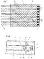
- the flexible body (“flab”) shown in FIG. 1 and enlarged in FIG. 2 exists from a block-shaped base material 1, in which several tubular catheters 2 are used.
- plugs 3 are inside of the base material 1 ends 4 of the catheter 2 are closed.
- the respective other ends 5 lead out of the base material 1 and are open, so that there is a radiation source into the interior of the can insert respective catheter 2.
- the body explained in the exemplary embodiment is shaped as a flat cuboid, in the individual catheters 2 in a common plane and parallel to each other are embedded.
- other forms of the body or other arrangements of the catheters 2 possible in it e.g. B. also the shaping of the body in the form of a cylinder.
- a tissue insert 6 is embedded in the base material 1 of the body, which is the flexible body that goes into the patient's body through surgery is implanted in terms of tensile forces.
- Radiation treatment must affect the area to be irradiated in the patient's body are on the side of the flexible body facing away from the tissue insert 6.
- the body consists of a preferably transparent plastic material which can be cast when heated.
- Body-friendly, soft plastics are particularly worth considering based on polyurethanes, polyolefins, polycarbonates, polyesters, Polyamides, polyethers, polyvinyl chloride, polysulfones and the like Polymers and silicones with or without plasticizers.
- the catheter 2 can for example made of polyamide.
- the plastic fabric for the fabric insert 6 should also meet the criterion of body-friendliness, since this during the implantation of the flab with the patient's body tissue must be sewn.
- the symmetrically designed stopper 3 Plastic is made up of a radially expanded central section 7 as well two end sections 8A, 8B together.
- the end portions 8A, 8B are at their End faces provided with blind holes 9, which as elements for connecting serve the plug 3 with other parts, as explained in more detail below will be.
- the outer diameter of the end portions 8A, 8B corresponds approximately the inside diameter of the catheter 2, the outside End section 8B also closes substantially flush with the end there 4 of the catheter 2.
- each individual catheter 2 is provided with a clamping ring 10, however, it is also possible to combine all or part of the clamping rings into one summarize common clamp, in which then the individual Bores 11 for the passage of the catheter 2 are located. Even the clamping rings 10 or the common clamping piece is made of plastic.
- the catheter 2 is also located around the closed end 4 the base material 1 so that the body except for the free openings of the catheter is completely complete.
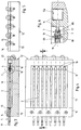
- a two-part mold 12 which consists of a Base body 13 and a clamp piece which can be fastened on the base body 13 14 composed.
- Base body 13 and clamping piece 14 are on her provide one end with semicircular bushings that are assembled add to holes 15 in which the catheters 2 with their free ends 5 are clamped.
- 12 alignment elements 16 can be inserted in recesses 12a of the shape, wherein an alignment element 16 is assigned to each catheter 2.
- the Alignment elements 16 aligned centrally on the catheters 2 engage pins 17 formed thereon and passing through the molding space 18 in the blind hole 9 in the end portion 8B of the respective plug 3.
- the alignment elements 16 can, as in Shown embodiment, arranged individually in the form 12. Likewise, the alignment elements 16 can also form a single component be summarized, which then the corresponding number of pins 17th having.
- the mold 12 is provided with a mold space 18 which is open at the top, whose shape corresponds exactly to the shape of the later body.
- a centering rod from the end 5 in each catheter 2 19 insert.
- the centering rod 19 is at its tip with a Serving as a connecting element 20 pin which is in the blind hole 9th of section 8A engages.
- the individual in the form 12 with the clamping piece 14 removed Catheter 2 inserted, at one end 4 already inserted Fabrics 3 and the outer clamping rings 10 provided are.
- the centering rods 19 are already in the catheter at this time 2 inserted and adjust the stopper 3 at the end of the catheter.
- the clamping rings 10 are in the axial direction against the radially widened central section 7 of the plug 3, so that the material of the respective catheter 2nd is clamped between the clamping ring 10 and the plug 3. This will create a very good axial fixation of the stopper 3 within the catheter is achieved.
- the catheters 2 thus prepared are then in the position shown in FIG the form 12 inserted, and at its ends 4 by positive engagement the pin of the alignment elements 16 centered in the plug 3. Subsequently the clamping piece 14 is placed on the base body 13 of the mold 12 and for example screwed.
- the prepared mold 12 is aligned on a level Place the plate in a forced air oven and mold for approx. 15 min. on a Preheated temperature of about 150 ° C.
- a Preheated temperature of about 150 ° C.
- the preheated form 12 is poured a portion of the liquid or gel-like mass for the base material, until the mold space 18 is filled so high with this mass that Catheter 2 and clamping rings 10 essentially enclosed and on are fixed this way.
- the mass forming a first layer in this way hardens or gels after about 10 min. at a temperature of 150 ° C.
- curing is meant the end of the gelling process, not one complete hardening of the material, which is rather always soft and flexible remains.
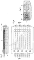
- the tissue insert 6 placed on the surface of the mass and lightly pressed. Subsequently further suspension is filled into the mold space 18 and this mass brought to gel, which also causes the tissue insert 16 into the base material 1 of the body is embedded. Finally the mold comes out of the oven taken and cooled. To remove the body from the form 12 must first the alignment elements 16 are removed, preferably by axial withdrawal from the mold space 18. This creates holes in the finally, base material heated to 160 ° C is injected. After that After cooling, the manufactured body is homogeneously closed on all sides.
- the alignment elements 16 can then be removed from the mold 12 after the first layer the mass has hardened. At this point, the catheters are already provisional fixed by the mass below, so that positional shifts are no longer possible. It is therefore after filling the first part of the volume first the alignment elements 16 are removed from the mold 12 and each replaced by a plug 21 which, other than that Alignment element 16, has no parts protruding into the mold space 18. When the second portion of the mass is then filled in, fill up then at the same time that when removing the alignment elements 16 in the molding space 18 holes created, so that ultimately a homogeneous closure is created.
Abstract
Description
Die Erfindung betrifft zunächst ein Verfahren zur Herstellung eines flexiblen Körpers mit darin eingebetteten Schläuchen oder Kathetern, insbesondere für die Strahlentherapie im Nachladeverfahren (After-Loading), bei dem die Schläuche oder Katheter in eine Form eingelegt und darin in definierter Lage und Ausrichtung fixiert werden, bevor zur Ausformung des Grundmaterials des Körpers eine flüssige oder gelartige Masse in den Formraum der Form eingefüllt wird und darin unter Einbettung der Schläuche oder Katheter aushärtet.The invention initially relates to a method for producing a flexible Body with tubes or catheters embedded therein, in particular for radiotherapy in the after-loading procedure, in which the Tubes or catheters placed in a mold and in a defined position and alignment are fixed before forming the base material the body is filled with a liquid or gel-like mass in the mold cavity is hardened and embedded in the tubing or catheter.
Derartige flexible Körper, oft auch als "Flabs" bezeichnet, dienen in der Medizintechnik dazu, auf kleinstem Raum konzentrierte Strahlenbehandlungen hoher Wirksamkeit durchzuführen. Die Strahlentherapie nach der After-Loading-Methode hat sich insbesondere bei der Behandlung von Tumoren bewährt. Zur Vermeidung einer Schädigung des gesunden Gewebes ist bei derartigen Therapien eine sehr genaue örtliche Planung der Bestrahlung sicherzustellen, weshalb die Katheter genau positioniert am Körper oder im körpereigenen Gewebe fixiert werden müssen.Such flexible bodies, often referred to as "flabs", are used in medical technology moreover, radiation treatments concentrated in the smallest space are higher Effectiveness. Radiotherapy according to the after-loading method has proven itself particularly in the treatment of tumors. For Such therapies prevent damage to healthy tissue ensure a very precise local planning of the radiation, which is why the catheter is positioned exactly on the body or in the body's own tissue must be fixed.
Ein Verfahren zur Herstellung derartiger Flabs ist z. B. aus der DE 195 26 690 A1 bekannt. In eine rechteckige, zweigeteilte Form werden zunächst über deren gesamte Länge die später einzubettenden, röhrchenförmigen Katheter eingesetzt. Anschließend wird eine Geliermasse in die Form gefüllt, so daß diese beim Aushärten die Katheter umschließt und hierbei einbettet. Zusätzlich kann ein Gewebematerial in das Material des so erzeugten Blockes mit eingebettet werden. A method for producing such flabs is e.g. B. from DE 195 26 690 A1 known. In a rectangular, two-part shape are first about their entire length of the tubular catheters to be embedded later. Then a gelling compound is filled into the mold so that it encloses the catheter during curing and embeds it. In addition can a fabric material is embedded in the material of the block thus produced become.
Während infolge der Einbettung der Verlauf der einzelnen Katheter sehr genau identifizierbar und während der Strahlentherapie reproduzierbar ist, bereitet die Identifikation eines bestimmten Applikationsortes in Längsrichtung der jeweiligen Katheter Schwierigkeiten.While due to the embedding the course of the individual catheters is very accurate identifiable and reproducible during radiation therapy, the Identification of a specific application location in the longitudinal direction of the respective one Catheter difficulties.
Der Erfindung liegt die Aufgabe zugrunde, die bekannten flexiblen Körper mit darin eingebetteten Schläuchen oder Kathetern so weiterzuentwickeln, daß bei deren Anwendung in der Strahlentherapie eine exaktere Positionierung der Strahlenquelle ermöglicht wird. Ferner soll ein Verfahren zur Herstellung derartiger flexibler Körper entwickelt werden.The object of the invention is to further develop the known flexible bodies with tubes or catheters embedded therein in such a way that their use in radiation therapy enables the radiation source to be positioned more precisely. A method for producing such flexible bodies is also to be developed.
Zur Lösung wird hinsichtlich des Verfahrens vorgeschlagen, daß die Schläuche oder Katheter in der Weise in die Form eingelegt werden, daß sich deren eine Enden noch innerhalb des Formraums der Form befinden, daß diese Enden dauerhaft verschlossen und daran vor Einfüllen der flüssigen oder gelartigen Masse Ausrichtelemente angesetzt werden, die sich an der Form abstützen.To solve the problem it is proposed with regard to the method that the tubes or catheters are inserted into the mold in such a way that their one ends are still within the mold's mold space, that these ends are permanently closed and alignment elements are filled with them before filling the liquid or gel-like mass be applied, which are based on the shape.
Die so hergestellten Flabs weisen daher keine durchgehenden Schläuche bzw. Katheter auf, sondern sind noch im Grundmaterial des Körpers mit Begrenzungen versehen. Diese Begrenzungen stellen in Längsrichtung jedes einzelnen Katheters exakt reproduzierbare Orte dar, die als Bezugspunkte bei der Festlegung der Ortskoordinaten des jeweils erforderlichen Applikationsortes dienen können. Auf diese Weise ist eine exakte Ortsbestimmung nicht nur quer zur Erstreckung der Katheter möglich, wozu der geeignete der parallel angeordneten Katheter ausgewählt wird, sondern auch in Längsrichtung des jeweiligen Katheters.The flabs produced in this way therefore have no through hoses or Catheter on, but are still in the body's basic material with limitations Mistake. These limits place in the longitudinal direction of each one Catheters represent precisely reproducible locations that serve as reference points when determining serve the location coordinates of the respectively required application location can. In this way, an exact location is not just across Extension of the catheter possible, for which purpose the suitable of the parallel arranged Catheter is selected, but also in the longitudinal direction of each Catheters.
Vorteilhafte Ausgestaltungen des Verfahrens sind in den Unteransprüchen beschrieben.Advantageous refinements of the method are described in the subclaims.
Hinsichtlich der Teilaufgabe, einen entsprechenden flexiblen Körper zu schaffen, wird mit der Erfindung vorgeschlagen ein flexibler Körper mit darin eingebetteten Schläuchen oder Kathetern, insbesondere für die Strahlentherapie im Nachladeverfahren (After-Loading), wobei sich die einen Enden der Schläuche oder Katheter innerhalb des Körpers befinden und dort verschlossen sind. With regard to the subtask to create a corresponding flexible body, the invention proposes a flexible body with embedded therein Tubes or catheters, especially for radiation therapy in the After-loading procedure, whereby one end of the hoses or catheters are inside the body and are closed there.
Auch zum Aufbau des flexiblen Körpers sind vorteilhafte Ausgestaltungen in den Unteransprüchen angegeben.Advantageous refinements are also shown in FIG specified in the subclaims.
Weitere Einzelheiten und Ausgestaltungen werden nachfolgend anhand der Zeichnung erläutert. Darin zeigen:
- Fig. 1
- in einer Ansicht einen erfindungsgemäß ausgebildeten flexiblen Körper ("Flab"),
- Fig. 2
- einen vergrößerten Teilausschnitt entlang der Ebene II-II der Fig. 1,
- Fig. 3
- in einer Schnittdarstellung eine Form zur Herstellung des flexiblen Körpers,
- Fig. 4
- in einer Draufsicht die Form nach Fig. 3 in geschlossenem Zustand,
- Fig. 5
- in einer Stirnansicht die Form nach Fig. 3,
- Fig. 6
- in vergrößerter Darstellung die Einzelheit VI gemäß Fig. 3,
- Fig. 7
- in einer der Fig. 3 entsprechenden Schnittdarstellung die Form zur Herstellung des flexiblen Körpers in einem späteren Verfahrensstadium,
- Fig. 8
- in einer Draufsicht die Form nach Fig. 7 und
- Fig. 9
- in einer vergrößerten Darstellung die Einzelheit IX gemäß Fig. 7.
- Fig. 1
- in a view a flexible body designed according to the invention (“flab”),
- Fig. 2
- 2 shows an enlarged partial section along the plane II-II of FIG. 1,
- Fig. 3
- a sectional view of a mold for producing the flexible body,
- Fig. 4
- 3 in a closed view,
- Fig. 5
- 3 in a front view,
- Fig. 6
- the detail VI of FIG. 3 in an enlarged view,
- Fig. 7
- 3 shows the sectional view corresponding to FIG. 3 for the production of the flexible body in a later process stage,
- Fig. 8
- in a plan view the shape of Fig. 7 and
- Fig. 9
- in an enlarged view the detail IX according to FIG. 7.
Der in Fig. 1 und vergrößert in Fig. 2 dargestellte flexible Körper ("Flab") besteht
aus einem blockförmigen Grundmaterial 1, in welches mehrere
schlauchförmige Katheter 2 eingesetzt sind. Mittels Stopfen 3 sind die sich innerhalb
des Grundmaterials 1 befindenden Enden 4 der Katheter 2 verschlossen.
Die jeweils anderen Enden 5 führen aus dem Grundmaterial 1 heraus und
sind offen, so daß sich hierdurch eine Strahlungsquelle bis in das Innere des
jeweiligen Katheters 2 einführen läßt. The flexible body ("flab") shown in FIG. 1 and enlarged in FIG. 2 exists
from a block-shaped base material 1, in which several
Der im Ausführungsbeispiel erläuterte Körper ist als flacher Quader geformt, in
den die einzelnen Katheter 2 in einer gemeinsamen Ebene und parallel zueinander
eingebettet sind. Je nach den therapeutischen Randbedingungen sind
auch andere Gestaltungen des Körpers oder andere Anordnungen der Katheter
2 darin möglich, z. B. auch die Formung des Körpers in Gestalt eines Zylinders.The body explained in the exemplary embodiment is shaped as a flat cuboid, in
the
In das Grundmaterial 1 des Körpers mit eingebettet ist eine Gewebeeinlage 6,
die den flexiblen Körper, der im Wege einer Operation in den Körper des Patienten
implantiert wird, hinsichtlich der Zugkräfte zu verstärken. Bei der
Strahlenbehandlung muß sich die zu bestrahlende Stelle im Körper des Patienten
auf der der Gewebeeinlage 6 abgewandten Seite des flexiblen Körpers befinden.A
Zur Bereitstellung der erforderlichen Flexibilität des Körpers besteht dieser aus
einem vorzugsweise transparenten, bei Erhitzung gießfähigen Kunststoffmaterial.
In Betracht zu ziehen sind insbesondere körperfreundliche, weiche Kunststoffe
auf Basis von Polyurethanen, Polyolefinen, Polycarbonaten, Polyestern,
Polyamiden, Polyethern, Polyvinylchlorid, Polysulfonen und entsprechenden
Polymeren und Silikonen mit oder ohne Weichmachern. Die Katheter 2 können
beispielsweise aus Polyamid bestehen. Das Kunststoffgewebe für die Gewebeeinlage
6 sollte ebenfalls das Kriterium der Körperfreundlichkeit erfüllen, da
dieses bei dem Implantieren des Flabs mit dem Körpergewebe des Patienten
vernäht werden muß.To provide the body with the necessary flexibility, it consists of
a preferably transparent plastic material which can be cast when heated.
Body-friendly, soft plastics are particularly worth considering
based on polyurethanes, polyolefins, polycarbonates, polyesters,
Polyamides, polyethers, polyvinyl chloride, polysulfones and the like
Polymers and silicones with or without plasticizers. The
Einzelheiten im Bereich der verschlossenen Enden der Katheter werden nachfolgend
anhand der Fig. 2 erläutert. Der symmetrisch gestaltete Stopfen 3 aus
Kunststoff setzt sich aus einem radial erweiterten Mittelabschnitt 7 sowie
zwei Endabschnitten 8A, 8B zusammen. Die Endabschnitte 8A, 8B sind an ihren
Stirnseiten mit Sacklöchern 9 versehen, die als Elemente zum Verbinden
des Stopfens 3 mit anderen Teilen dienen, wie nachfolgend noch näher erläutert
werden wird. Der äußere Durchmesser der Endabschnitte 8A, 8B entspricht
in etwa dem Innendurchmesser des Katheters 2, der außen gelegene
Endabschnitt 8B schließt ferner im wesentlichen bündig mit dem dortigen Ende
4 des Katheters 2 ab. Details in the area of the closed ends of the catheters are given below
explained with reference to FIG. 2. The symmetrically designed
Im Bereich des nach innen weisenden Endabschnittes 8A des Stopfens 3 sitzt
auf der Mantelfläche des Katheters 2 ein Klemmring 10 auf. Beim Ausführungsbeispiel
ist jeder einzelne Katheter 2 mit einem Klemmring 10 versehen,
es ist jedoch gleichfalls möglich, alle oder einen Teil der Klemmringe zu einem
gemeinsamen Klemmstück zusammenzufassen, in dem sich dann die einzelnen
Bohrungen 11 zur Durchführung der Katheter 2 befinden. Auch die Klemmringe
10 bzw. das gemeinsame Klemmstück besteht aus Kunststoff.Sits in the area of the
Um das verschlossene Ende 4 der Katheter 2 herum befindet sich ebenfalls
das Grundmaterial 1, so daß der Körper bis auf die freien Öffnungen der Katheter
vollkommen abgeschlossen ist.The
Anhand der Figuren 3 bis 9 wird nunmehr die Herstellung des Körpers erläutert.
Hierzu wird eine zweiteilige Form 12 verwendet, die sich aus einem
Grundkörper 13 und einem auf dem Grundkörper 13 befestigbaren Klemmstück
14 zusammensetzt. Grundkörper 13 und Klemmstück 14 sind an ihrem
einen Ende mit halbkreisförmigen Durchführungen versehen, die sich zusammengesetzt
zu Bohrungen 15 fügen, in denen einzeln die Katheter 2 mit ihren
freien Enden 5 festgespannt sind. Im Bereich der anderen Enden 5 der Katheter
2 sind in Aussparungen 12a der Form 12 Ausrichtelemente 16 einsetzbar,
wobei jeweils ein Ausrichtelement 16 jedem Katheter 2 zugeordnet ist. Die
zentrisch auf die Katheter 2 ausgerichteten Ausrichtelemente 16 greifen mit
daran ausgebildeten, durch den Formraum 18 hindurchführenden Zapfen 17 in
das Sackloch 9 im Endabschnitt 8B des jeweiligen Stopfens 3 ein. Hierdurch
wird erreicht, daß das mit dem Stopfen 3 verschlossene Ende des Katheters 2
exakt in der Form ausgerichtet ist. Die Ausrichtelemente 16 können, wie beim
Ausführungsbeispiel dargestellt, einzeln in der Form 12 angeordnet sein.
Ebenso können die Ausrichtelemente 16 aber auch zu einem einzigen Bauteil
zusammengefaßt sein, welches dann die entsprechende Zahl an Zapfen 17
aufweist.The production of the body will now be explained with reference to FIGS. 3 to 9.
For this purpose, a two-
Schließlich ist die Form 12 mit einem nach oben offenen Formraum 18 versehen,
dessen Gestalt exakt der Gestalt des späteren Körpers entspricht. Damit
die sich durch den Formraum 18 hindurch erstreckenden Katheter 2 nicht
durchhängen, läßt sich von dem Ende 5 her in jeden Katheter 2 eine Zentrierstange
19 einführen. Auch die Zentrierstange 19 ist an ihrer Spitze mit einem
als Verbindungselement 20 dienenden Zapfen versehen, der in das Sackloch 9
des Abschnitts 8A eingreift.Finally, the
Zunächst werden in die Form 12 bei abgenommenem Klemmstück 14 die einzelnen
Katheter 2 eingelegt, die an ihrem einen Ende 4 bereits mit den eingesetzten
Stoffen 3 sowie den außen aufgesetzten Klemmringen 10 versehen
sind. Auch die Zentrierstangen 19 sind zu diesem Zeitpunkt bereits in die Katheter
2 eingeführt und justieren die Stopfen 3 am Katheterende. Die Klemmringe
10 sind in axialer Richtung gegen den radial erweiterten Mittelabschnitt
7 des Stopfens 3 geschoben, so daß das Material des jeweiligen Katheters 2
zwischen Klemmring 10 und Stopfen 3 eingespannt wird. Hierdurch wird eine
sehr gute axiale Fixierung des Stopfens 3 innerhalb des Katheters erreicht.First, the individual in the
Die so vorbereiteten Katheter 2 werden dann in der in Fig. 3 gezeigten Lage in
die Form 12 eingelegt, und an ihren Enden 4 durch formschlüssiges Eingreifen
der Zapfen der Ausrichtelemente 16 in die Stopfen 3 zentriert. Anschließend
wird das Klemmstück 14 auf den Grundkörper 13 der Form 12 aufgesetzt und
beispielsweise verschraubt.The
Sodann wird die vorbereitete Form 12 auf einer waagerecht ausgerichteten
Platte in einem Umluftofen plaziert und die Form für ca. 15 min. auf eine
Temperatur von etwa 150 °C vorgeheizt. In die so vorgeheizte Form 12 wird
eine Teilmenge der flüssigen oder gelartigen Masse für das Grundmaterial eingegossen,
bis der Formraum 18 so hoch mit dieser Masse angefüllt ist, daß
Katheter 2 und Klemmringe 10 im wesentlichen davon eingeschlossen und auf
diese Weise fixiert sind. Die auf diese Weise eine erste Lage bildende Masse
härtet aus bzw. geliert nach etwa 10 min. bei einer Temperatur von 150 °C.
Mit "Aushärten" ist hier der Abschluß des Gelierprozesses gemeint, nicht ein
völliges Verhärten des Materials, welches vielmehr stets weich und flexibel
bleibt.Then the
In einem weiteren Verfahrensschritt wird anschließend die Gewebeeinlage 6
auf die Oberfläche der Masse aufgelegt und leicht angedrückt. Anschließend
wird weitere Suspension in den Formraum 18 eingefüllt und auch diese Masse
zum Gelieren gebracht, wodurch auch die Gewebeeinlage 16 in das Grundmaterial
1 des Körpers eingebettet wird. Schließlich wird die Form aus dem Ofen
genommen und abgekühlt. Zur Entnahme des Körpers aus der Form 12 müssen
zunächst die Ausrichtelemente 16 entfernt werden, vorzugsweise durch
axiales Zurückziehen aus dem Formraum 18. Hierbei entstehen Löcher, in die
abschließend auf 160 °C erhitztes Grundmaterial eingespritzt wird. Nach dessen
Abkühlung ist der hergestellte Körper allseitig homogen geschlossen.In a further process step, the
Zum Schließen der bei dem Zurückziehen der Ausrichtelemente 16 zwangsläufig
entstehenden Löcher ist es alternativ auch möglich, die Ausrichtelemente
16 bereits dann aus der Form 12 herauszunehmen, nachdem die erste Lage
der Masse ausgehärtet ist. Zu diesem Zeitpunkt sind die Katheter bereits vorläufig
durch die unterhalb befindliche Masse fixiert, so daß Lageverschiebungen
nicht mehr möglich sind. Es werden daher nach Einfüllen des ersten Teilvolumens
der Masse zunächst die Ausrichtelemente 16 aus der Form 12 herausgenommen
und jeweils durch einen Stopfen 21 ersetzt, der, anders als das
Ausrichtelement 16, keine in den Formraum 18 hineinragenden Teile aufweist.
Bei dem anschließenden Einfüllen des zweiten Anteiles der Masse füllen sich
dann zugleich die beim Herausnehmen der Ausrichtelemente 16 im Formraum
18 entstandenen Löcher, so daß letztlich ein homogener Verschluß entsteht.To close the inevitable when retracting the
Die vollständig mit der Masse gefüllte Form ist in den Figuren 7 bis 9 dargestellt. The shape completely filled with the mass is shown in FIGS. 7 to 9.
- 11
- GrundmaterialBasic material
- 22nd
- Katheter, SchlauchCatheter, tube
- 33rd
- StopfenPlug
- 44th
- geschlossenes Ende des Kathetersclosed end of the catheter
- 55
- offenes Ende des Kathetersopen end of the catheter
- 66
- GewebeeinlageFabric insert
- 77
- Mittelabschnitt des StopfensMidsection of the stopper
- 8A8A
- Endabschnitt des StopfensEnd section of the plug
- 8B8B
- Endabschnitt des StopfensEnd section of the plug
- 99
- SacklochBlind hole
- 1010th
- KlemmringClamping ring
- 1111
- Bohrungdrilling
- 1212th
- Formshape
- 12a12a
- Aussparung der FormCutout of the shape
- 1313
- GrundkörperBasic body
- 1414
- KlemmstückClamp
- 1515
- Bohrungdrilling
- 1616
- AusrichtelementAlignment element
- 1717th
- ZapfenCones
- 1818th
- FormraumMolding space
- 1919th
- ZentrierstangeCentering rod
- 2020th
- VerbindungselementFastener
- 2121
- StopfenPlug
Claims (12)
dadurch gekennzeichnet,
daß die Schläuche oder Katheter (2) in der Weise in die Form (12) eingelegt werden, daß sich deren eine Enden (4) noch innerhalb des Formraums (18) der Form (12) befinden, daß diese Enden (4) dauerhaft verschlossen und daran vor Einfüllen der flüssigen oder gelartigen Masse Ausrichtelemente (16) angesetzt werden, die sich an der Form (12) abstützen.Process for the production of a flexible body with tubes or catheters embedded therein, in particular for radiation therapy in the after-loading process, in which the tubes or catheters (2) are inserted into a mold (12) and fixed therein in a defined position and orientation before a liquid or gel-like mass is poured into the mold space (18) of the mold and cures therein by embedding the tubing or catheter (2) to form the base material (1) of the body,
characterized,
that the tubes or catheters (2) are inserted into the mold (12) in such a way that their one ends (4) are still inside the mold space (18) of the mold (12) such that these ends (4) are permanently closed and alignment elements (16), which are supported on the mold (12), are attached to it before filling the liquid or gel-like mass.
dadurch gekennzeichnet,
daß sich die einen Enden (4) der Schläuche oder Katheter (2) innerhalb des Körpers befinden und dort verschlossen sind.Flexible body with tubes or catheters embedded in it, especially for radiotherapy in the after-loading procedure (after-loading),
characterized,
that the one ends (4) of the tubes or catheters (2) are inside the body and are closed there.
Applications Claiming Priority (2)
| Application Number | Priority Date | Filing Date | Title |
|---|---|---|---|
| DE19743877A DE19743877B4 (en) | 1997-10-04 | 1997-10-04 | Flexible body with hoses or catheters embedded therein, in particular for radiation therapy and method for its production |
| DE19743877 | 1997-10-04 |
Publications (3)
| Publication Number | Publication Date |
|---|---|
| EP0906769A2 true EP0906769A2 (en) | 1999-04-07 |
| EP0906769A3 EP0906769A3 (en) | 2000-03-15 |
| EP0906769B1 EP0906769B1 (en) | 2004-06-30 |
Family
ID=7844586
Family Applications (1)
| Application Number | Title | Priority Date | Filing Date |
|---|---|---|---|
| EP98116921A Expired - Lifetime EP0906769B1 (en) | 1997-10-04 | 1998-09-08 | Flexible body with inside tubes or catheters,particularly suited for the therapy by rays,and its manufacturing process |
Country Status (5)
| Country | Link |
|---|---|
| EP (1) | EP0906769B1 (en) |
| JP (1) | JPH11216185A (en) |
| AT (1) | ATE270131T1 (en) |
| DE (2) | DE19743877B4 (en) |
| IL (1) | IL126454A0 (en) |
Cited By (10)
| Publication number | Priority date | Publication date | Assignee | Title |
|---|---|---|---|---|
| US7497819B2 (en) | 2004-11-05 | 2009-03-03 | Theragenics Corporation | Expandable brachytherapy device |
| WO2012149581A1 (en) * | 2011-04-28 | 2012-11-01 | Peter Nakaji | Apparatus for loading dosimetrically customizable brachytherapy carriers |
| US9403033B1 (en) | 2015-04-24 | 2016-08-02 | Gammatile Llc | Apparatus and method for loading radioactive seeds into carriers |
| US9492683B2 (en) | 2013-03-15 | 2016-11-15 | Gammatile Llc | Dosimetrically customizable brachytherapy carriers and methods thereof in the treatment of tumors |
| US9526463B2 (en) | 2015-05-06 | 2016-12-27 | Gammatile Llc | Radiation shielding |
| US9821174B1 (en) | 2015-02-06 | 2017-11-21 | Gammatile Llc | Radioactive implant planning system and placement guide system |
| US10350431B2 (en) | 2011-04-28 | 2019-07-16 | Gt Medical Technologies, Inc. | Customizable radioactive carriers and loading system |
| US10888710B1 (en) | 2016-11-29 | 2021-01-12 | Gt Medical Technologies, Inc. | Transparent loading apparatus |
| US10981018B2 (en) | 2019-02-14 | 2021-04-20 | Gt Medical Technologies, Inc. | Radioactive seed loading apparatus |
| US11130004B2 (en) | 2005-11-10 | 2021-09-28 | Cianna Medical, Inc. | Brachytherapy apparatus and methods for using them |
Families Citing this family (7)
| Publication number | Priority date | Publication date | Assignee | Title |
|---|---|---|---|---|
| DE60324448D1 (en) | 2002-09-10 | 2008-12-11 | Cianna Medical Inc | brachytherapy |
| WO2007053823A2 (en) | 2005-10-31 | 2007-05-10 | Biolucent, Inc. | Brachytherapy apparatus and methods of using same |
| US7887476B2 (en) | 2005-11-10 | 2011-02-15 | Cianna Medical, Inc. | Helical brachytherapy apparatus and methods of using same |
| JP5213851B2 (en) | 2006-06-02 | 2013-06-19 | シアンナ・メディカル・インコーポレイテッド | Expandable brachytherapy device |
| US7862498B2 (en) | 2006-10-08 | 2011-01-04 | Cianna Medical, Inc. | Expandable brachytherapy apparatus and methods for using them |
| US8517907B2 (en) | 2007-12-16 | 2013-08-27 | Cianna Medical, Inc. | Expandable brachytherapy apparatus and methods for using them |
| WO2010022103A1 (en) | 2008-08-18 | 2010-02-25 | Cianna Medical, Inc. | Brachytherapy apparatus, systems, and methods for using them |
Citations (1)
| Publication number | Priority date | Publication date | Assignee | Title |
|---|---|---|---|---|
| DE19526690A1 (en) | 1995-07-21 | 1997-01-23 | Huels Chemische Werke Ag | Process for the production of a flexible fixation material with catheters or tubes for radiotherapy |
Family Cites Families (3)
| Publication number | Priority date | Publication date | Assignee | Title |
|---|---|---|---|---|
| US4706652A (en) * | 1985-12-30 | 1987-11-17 | Henry Ford Hospital | Temporary radiation therapy |
| DE4342589C2 (en) * | 1993-12-14 | 1998-07-09 | Optische Ind De Oude Delft Nv | Medical radiation therapy device |
| DE19526680A1 (en) * | 1995-07-21 | 1997-01-23 | Huels Chemische Werke Ag | Flexible, adaptable plastic body with single catheters or equidistantly embedded catheters or sleeves for the introduction of catheters for radiation therapy |
-
1997
- 1997-10-04 DE DE19743877A patent/DE19743877B4/en not_active Expired - Fee Related
-
1998
- 1998-09-08 AT AT98116921T patent/ATE270131T1/en active
- 1998-09-08 DE DE59811626T patent/DE59811626D1/en not_active Expired - Lifetime
- 1998-09-08 EP EP98116921A patent/EP0906769B1/en not_active Expired - Lifetime
- 1998-09-30 JP JP10312645A patent/JPH11216185A/en active Pending
- 1998-10-04 IL IL12645498A patent/IL126454A0/en unknown
Patent Citations (1)
| Publication number | Priority date | Publication date | Assignee | Title |
|---|---|---|---|---|
| DE19526690A1 (en) | 1995-07-21 | 1997-01-23 | Huels Chemische Werke Ag | Process for the production of a flexible fixation material with catheters or tubes for radiotherapy |
Cited By (24)
| Publication number | Priority date | Publication date | Assignee | Title |
|---|---|---|---|---|
| US7497820B2 (en) | 2004-11-05 | 2009-03-03 | Theragenics Corporation | Expandable brachytherapy device |
| US7497819B2 (en) | 2004-11-05 | 2009-03-03 | Theragenics Corporation | Expandable brachytherapy device |
| US11130004B2 (en) | 2005-11-10 | 2021-09-28 | Cianna Medical, Inc. | Brachytherapy apparatus and methods for using them |
| US9022915B2 (en) | 2011-04-28 | 2015-05-05 | Gammatile Llc | Dosimetrically customizable brachytherapy carriers and methods thereof in the treatment of tumors |
| WO2012149581A1 (en) * | 2011-04-28 | 2012-11-01 | Peter Nakaji | Apparatus for loading dosimetrically customizable brachytherapy carriers |
| US11413473B2 (en) | 2011-04-28 | 2022-08-16 | Gt Medical Technologies, Inc. | Customizable radioactive carriers and loading system |
| US9409038B2 (en) | 2011-04-28 | 2016-08-09 | Gammatile Llc | Apparatus for loading dosimetrically customizable brachytherapy carriers |
| US8974364B1 (en) | 2011-04-28 | 2015-03-10 | Gammatile Llc | Dosimetrically customizable brachytherapy carriers and methods thereof in the treatment of tumors |
| US10350431B2 (en) | 2011-04-28 | 2019-07-16 | Gt Medical Technologies, Inc. | Customizable radioactive carriers and loading system |
| US9545525B2 (en) | 2011-04-28 | 2017-01-17 | Gammatile Llc | Dosimetrically customizable brachytherapy carriers and methods thereof in the treatment of tumors |
| EP3456384A1 (en) * | 2011-04-28 | 2019-03-20 | GT Medical Technologies, Inc. | Dosimetrically customizable brachytherapy carriers |
| US9492683B2 (en) | 2013-03-15 | 2016-11-15 | Gammatile Llc | Dosimetrically customizable brachytherapy carriers and methods thereof in the treatment of tumors |
| US10265542B2 (en) | 2013-03-15 | 2019-04-23 | Gt Medical Technologies, Inc. | Dosimetrically customizable brachytherapy carriers and methods thereof in the treatment of tumors |
| US11278736B2 (en) | 2013-03-15 | 2022-03-22 | Gt Medical Technologies, Inc. | Dosimetrically customizable brachytherapy carriers and methods thereof in the treatment of tumors |
| US9821174B1 (en) | 2015-02-06 | 2017-11-21 | Gammatile Llc | Radioactive implant planning system and placement guide system |
| US11679275B1 (en) | 2015-02-06 | 2023-06-20 | Gt Medical Technologies, Inc. | Radioactive implant planning system and placement guide system |
| US10583310B1 (en) | 2015-02-06 | 2020-03-10 | Gt Medical Technologies, Inc. | Radioactive implant planning system and placement guide system |
| US10080909B2 (en) | 2015-04-24 | 2018-09-25 | Gt Medical Technologies, Inc. | Apparatus and method for loading radioactive seeds into carriers |
| US9403033B1 (en) | 2015-04-24 | 2016-08-02 | Gammatile Llc | Apparatus and method for loading radioactive seeds into carriers |
| US10085699B2 (en) | 2015-05-06 | 2018-10-02 | Gt Medical Technologies, Inc. | Radiation shielding |
| US9526463B2 (en) | 2015-05-06 | 2016-12-27 | Gammatile Llc | Radiation shielding |
| US10888710B1 (en) | 2016-11-29 | 2021-01-12 | Gt Medical Technologies, Inc. | Transparent loading apparatus |
| US11673002B2 (en) | 2016-11-29 | 2023-06-13 | Gt Medical Technologies, Inc. | Transparent loading apparatus |
| US10981018B2 (en) | 2019-02-14 | 2021-04-20 | Gt Medical Technologies, Inc. | Radioactive seed loading apparatus |
Also Published As
| Publication number | Publication date |
|---|---|
| EP0906769B1 (en) | 2004-06-30 |
| JPH11216185A (en) | 1999-08-10 |
| EP0906769A3 (en) | 2000-03-15 |
| DE19743877A1 (en) | 1999-04-08 |
| IL126454A0 (en) | 1999-08-17 |
| DE19743877B4 (en) | 2008-01-31 |
| DE59811626D1 (en) | 2004-08-05 |
| ATE270131T1 (en) | 2004-07-15 |
Similar Documents
| Publication | Publication Date | Title |
|---|---|---|
| EP0906769B1 (en) | Flexible body with inside tubes or catheters,particularly suited for the therapy by rays,and its manufacturing process | |
| DE69530929T2 (en) | Irradiationskatheter | |
| DE69930382T2 (en) | ELECTRODE MATRIX FOR COCHLEAR IMPLANT | |
| DE3138311C2 (en) | ||
| DE69723089T2 (en) | ENDODONTIC INSERT PRE-IMPREGNATED WITH FIBER REINFORCEMENT FOR FILLING A TOOTH ROOT CHANNEL | |
| DE19721703A1 (en) | Catheter system with high kink resistance | |
| DE4446061A1 (en) | Catheter with reduced diameter stepped end section | |
| DE2546283A1 (en) | USE FOR APPLICATION PREFERABLY IN VASCULAR SURGERY | |
| DE3240468A1 (en) | SURGICAL IMPLANT | |
| DE102007023129A1 (en) | A process for the production of a plastic product with a plastic hard component and a plastic soft component as well as plastic product produced by the process | |
| EP0260484A1 (en) | External fixation apparatus | |
| EP0442256A2 (en) | Bone implant | |
| DE2313271A1 (en) | ADDITIONAL ELEMENT FOR IMPLANTS, METHOD OF MANUFACTURING THE ADDITIONAL ELEMENT AND FOR ITS FIXING TO A DEVICE, AND HEART VALVE WITH SUCH A SUSPENSION ELEMENT | |
| DE102020111458A1 (en) | Flexible endoscope with a skeletal structure | |
| DE3840436C2 (en) | ||
| AT256331B (en) | Device for taking blood | |
| DE60110791T2 (en) | THERMOPLASTIC MATERIAL APPARATUS AND ASSOCIATED TWO-STAGE CASTING METHOD | |
| WO1993010849A1 (en) | Canula, in particular for vascular puncture | |
| DE69811816T2 (en) | Process for molding a substantially cylindrical hollow composite article and molding tool for producing the same | |
| DE4437989A1 (en) | Process for the production of joint discs | |
| EP1364670A2 (en) | Single-use syringe and process for producing it | |
| DE102006059250A1 (en) | Arrangement for manufacturing brushes has injection tool with first half for holding brush parts with bristle bundles, second half in contact with bundle fixing ends forming cavities for injection material near individual fixing ends | |
| DE10201796A1 (en) | Method and device for controlling the shrinkage behavior during the primary shaping of plastics | |
| EP1786355A1 (en) | Superstructure body for a dental crown superstructure system | |
| DE19513451A1 (en) | Thermoplastic bristle and pressure injection moulded head brush mfr. |
Legal Events
| Date | Code | Title | Description |
|---|---|---|---|
| PUAI | Public reference made under article 153(3) epc to a published international application that has entered the european phase |
Free format text: ORIGINAL CODE: 0009012 |
|
| AK | Designated contracting states |
Kind code of ref document: A2 Designated state(s): AT CH DE LI |
|
| AX | Request for extension of the european patent |
Free format text: AL;LT;LV;MK;RO;SI |
|
| PUAL | Search report despatched |
Free format text: ORIGINAL CODE: 0009013 |
|
| AK | Designated contracting states |
Kind code of ref document: A3 Designated state(s): AT BE CH CY DE DK ES FI FR GB GR IE IT LI LU MC NL PT SE |
|
| AX | Request for extension of the european patent |
Free format text: AL;LT;LV;MK;RO;SI |
|
| RIC1 | Information provided on ipc code assigned before grant |
Free format text: 7A 61N 5/00 A, 7A 61N 5/10 B |
|
| 17P | Request for examination filed |
Effective date: 20000907 |
|
| AKX | Designation fees paid |
Free format text: AT CH DE LI |
|
| 17Q | First examination report despatched |
Effective date: 20030704 |
|
| GRAP | Despatch of communication of intention to grant a patent |
Free format text: ORIGINAL CODE: EPIDOSNIGR1 |
|
| GRAS | Grant fee paid |
Free format text: ORIGINAL CODE: EPIDOSNIGR3 |
|
| GRAA | (expected) grant |
Free format text: ORIGINAL CODE: 0009210 |
|
| RIC1 | Information provided on ipc code assigned before grant |
Ipc: 7A 61N 5/10 A |
|
| AK | Designated contracting states |
Kind code of ref document: B1 Designated state(s): AT CH DE LI |
|
| REG | Reference to a national code |
Ref country code: CH Ref legal event code: EP |
|
| REF | Corresponds to: |
Ref document number: 59811626 Country of ref document: DE Date of ref document: 20040805 Kind code of ref document: P |
|
| PLBE | No opposition filed within time limit |
Free format text: ORIGINAL CODE: 0009261 |
|
| STAA | Information on the status of an ep patent application or granted ep patent |
Free format text: STATUS: NO OPPOSITION FILED WITHIN TIME LIMIT |
|
| 26N | No opposition filed |
Effective date: 20050331 |
|
| PGFP | Annual fee paid to national office [announced via postgrant information from national office to epo] |
Ref country code: CH Payment date: 20110926 Year of fee payment: 14 |
|
| PGFP | Annual fee paid to national office [announced via postgrant information from national office to epo] |
Ref country code: DE Payment date: 20120928 Year of fee payment: 15 |
|
| PGFP | Annual fee paid to national office [announced via postgrant information from national office to epo] |
Ref country code: AT Payment date: 20120919 Year of fee payment: 15 |
|
| REG | Reference to a national code |
Ref country code: CH Ref legal event code: PL |
|
| REG | Reference to a national code |
Ref country code: AT Ref legal event code: MM01 Ref document number: 270131 Country of ref document: AT Kind code of ref document: T Effective date: 20130908 |
|
| REG | Reference to a national code |
Ref country code: DE Ref legal event code: R119 Ref document number: 59811626 Country of ref document: DE Effective date: 20140401 |
|
| PG25 | Lapsed in a contracting state [announced via postgrant information from national office to epo] |
Ref country code: LI Free format text: LAPSE BECAUSE OF NON-PAYMENT OF DUE FEES Effective date: 20130930 Ref country code: CH Free format text: LAPSE BECAUSE OF NON-PAYMENT OF DUE FEES Effective date: 20130930 |
|
| PG25 | Lapsed in a contracting state [announced via postgrant information from national office to epo] |
Ref country code: DE Free format text: LAPSE BECAUSE OF NON-PAYMENT OF DUE FEES Effective date: 20140401 Ref country code: AT Free format text: LAPSE BECAUSE OF NON-PAYMENT OF DUE FEES Effective date: 20130908 |