EP0906786A2 - System and method for one-way spray/aerosol tip - Google Patents
System and method for one-way spray/aerosol tip Download PDFInfo
- Publication number
- EP0906786A2 EP0906786A2 EP98307246A EP98307246A EP0906786A2 EP 0906786 A2 EP0906786 A2 EP 0906786A2 EP 98307246 A EP98307246 A EP 98307246A EP 98307246 A EP98307246 A EP 98307246A EP 0906786 A2 EP0906786 A2 EP 0906786A2
- Authority
- EP
- European Patent Office
- Prior art keywords
- outlet
- rigid shaft
- normally
- flexible
- liquid
- Prior art date
- Legal status (The legal status is an assumption and is not a legal conclusion. Google has not performed a legal analysis and makes no representation as to the accuracy of the status listed.)
- Granted
Links
Images


Classifications
-
- B—PERFORMING OPERATIONS; TRANSPORTING
- B65—CONVEYING; PACKING; STORING; HANDLING THIN OR FILAMENTARY MATERIAL
- B65D—CONTAINERS FOR STORAGE OR TRANSPORT OF ARTICLES OR MATERIALS, e.g. BAGS, BARRELS, BOTTLES, BOXES, CANS, CARTONS, CRATES, DRUMS, JARS, TANKS, HOPPERS, FORWARDING CONTAINERS; ACCESSORIES, CLOSURES, OR FITTINGS THEREFOR; PACKAGING ELEMENTS; PACKAGES
- B65D83/00—Containers or packages with special means for dispensing contents
- B65D83/14—Containers or packages with special means for dispensing contents for delivery of liquid or semi-liquid contents by internal gaseous pressure, i.e. aerosol containers comprising propellant for a product delivered by a propellant
- B65D83/28—Nozzles, nozzle fittings or accessories specially adapted therefor
-
- B—PERFORMING OPERATIONS; TRANSPORTING
- B05—SPRAYING OR ATOMISING IN GENERAL; APPLYING FLUENT MATERIALS TO SURFACES, IN GENERAL
- B05B—SPRAYING APPARATUS; ATOMISING APPARATUS; NOZZLES
- B05B11/00—Single-unit hand-held apparatus in which flow of contents is produced by the muscular force of the operator at the moment of use
- B05B11/0005—Components or details
- B05B11/0062—Outlet valves actuated by the pressure of the fluid to be sprayed
- B05B11/007—Outlet valves actuated by the pressure of the fluid to be sprayed being opened by deformation of a sealing element made of resiliently deformable material, e.g. flaps, skirts, duck-bill valves
-
- B—PERFORMING OPERATIONS; TRANSPORTING
- B05—SPRAYING OR ATOMISING IN GENERAL; APPLYING FLUENT MATERIALS TO SURFACES, IN GENERAL
- B05B—SPRAYING APPARATUS; ATOMISING APPARATUS; NOZZLES
- B05B1/00—Nozzles, spray heads or other outlets, with or without auxiliary devices such as valves, heating means
- B05B1/34—Nozzles, spray heads or other outlets, with or without auxiliary devices such as valves, heating means designed to influence the nature of flow of the liquid or other fluent material, e.g. to produce swirl
- B05B1/3405—Nozzles, spray heads or other outlets, with or without auxiliary devices such as valves, heating means designed to influence the nature of flow of the liquid or other fluent material, e.g. to produce swirl to produce swirl
- B05B1/341—Nozzles, spray heads or other outlets, with or without auxiliary devices such as valves, heating means designed to influence the nature of flow of the liquid or other fluent material, e.g. to produce swirl to produce swirl before discharging the liquid or other fluent material, e.g. in a swirl chamber upstream the spray outlet
- B05B1/3421—Nozzles, spray heads or other outlets, with or without auxiliary devices such as valves, heating means designed to influence the nature of flow of the liquid or other fluent material, e.g. to produce swirl to produce swirl before discharging the liquid or other fluent material, e.g. in a swirl chamber upstream the spray outlet with channels emerging substantially tangentially in the swirl chamber
- B05B1/3431—Nozzles, spray heads or other outlets, with or without auxiliary devices such as valves, heating means designed to influence the nature of flow of the liquid or other fluent material, e.g. to produce swirl to produce swirl before discharging the liquid or other fluent material, e.g. in a swirl chamber upstream the spray outlet with channels emerging substantially tangentially in the swirl chamber the channels being formed at the interface of cooperating elements, e.g. by means of grooves
- B05B1/3436—Nozzles, spray heads or other outlets, with or without auxiliary devices such as valves, heating means designed to influence the nature of flow of the liquid or other fluent material, e.g. to produce swirl to produce swirl before discharging the liquid or other fluent material, e.g. in a swirl chamber upstream the spray outlet with channels emerging substantially tangentially in the swirl chamber the channels being formed at the interface of cooperating elements, e.g. by means of grooves the interface being a plane perpendicular to the outlet axis
-
- B—PERFORMING OPERATIONS; TRANSPORTING
- B05—SPRAYING OR ATOMISING IN GENERAL; APPLYING FLUENT MATERIALS TO SURFACES, IN GENERAL
- B05B—SPRAYING APPARATUS; ATOMISING APPARATUS; NOZZLES
- B05B11/00—Single-unit hand-held apparatus in which flow of contents is produced by the muscular force of the operator at the moment of use
- B05B11/0005—Components or details
- B05B11/0062—Outlet valves actuated by the pressure of the fluid to be sprayed
- B05B11/0072—A valve member forming part of an outlet opening
-
- B—PERFORMING OPERATIONS; TRANSPORTING
- B05—SPRAYING OR ATOMISING IN GENERAL; APPLYING FLUENT MATERIALS TO SURFACES, IN GENERAL
- B05B—SPRAYING APPARATUS; ATOMISING APPARATUS; NOZZLES
- B05B11/00—Single-unit hand-held apparatus in which flow of contents is produced by the muscular force of the operator at the moment of use
- B05B11/0005—Components or details
- B05B11/0062—Outlet valves actuated by the pressure of the fluid to be sprayed
- B05B11/0075—Two outlet valves being placed in a delivery conduit, one downstream the other
-
- B—PERFORMING OPERATIONS; TRANSPORTING
- B65—CONVEYING; PACKING; STORING; HANDLING THIN OR FILAMENTARY MATERIAL
- B65D—CONTAINERS FOR STORAGE OR TRANSPORT OF ARTICLES OR MATERIALS, e.g. BAGS, BARRELS, BOTTLES, BOXES, CANS, CARTONS, CRATES, DRUMS, JARS, TANKS, HOPPERS, FORWARDING CONTAINERS; ACCESSORIES, CLOSURES, OR FITTINGS THEREFOR; PACKAGING ELEMENTS; PACKAGES
- B65D83/00—Containers or packages with special means for dispensing contents
- B65D83/14—Containers or packages with special means for dispensing contents for delivery of liquid or semi-liquid contents by internal gaseous pressure, i.e. aerosol containers comprising propellant for a product delivered by a propellant
- B65D83/16—Containers or packages with special means for dispensing contents for delivery of liquid or semi-liquid contents by internal gaseous pressure, i.e. aerosol containers comprising propellant for a product delivered by a propellant characterised by the actuating means
- B65D83/20—Containers or packages with special means for dispensing contents for delivery of liquid or semi-liquid contents by internal gaseous pressure, i.e. aerosol containers comprising propellant for a product delivered by a propellant characterised by the actuating means operated by manual action, e.g. button-type actuator or actuator caps
-
- B—PERFORMING OPERATIONS; TRANSPORTING
- B65—CONVEYING; PACKING; STORING; HANDLING THIN OR FILAMENTARY MATERIAL
- B65D—CONTAINERS FOR STORAGE OR TRANSPORT OF ARTICLES OR MATERIALS, e.g. BAGS, BARRELS, BOTTLES, BOXES, CANS, CARTONS, CRATES, DRUMS, JARS, TANKS, HOPPERS, FORWARDING CONTAINERS; ACCESSORIES, CLOSURES, OR FITTINGS THEREFOR; PACKAGING ELEMENTS; PACKAGES
- B65D83/00—Containers or packages with special means for dispensing contents
- B65D83/14—Containers or packages with special means for dispensing contents for delivery of liquid or semi-liquid contents by internal gaseous pressure, i.e. aerosol containers comprising propellant for a product delivered by a propellant
- B65D83/44—Valves specially adapted therefor; Regulating devices
Landscapes
- Chemical & Material Sciences (AREA)
- Dispersion Chemistry (AREA)
- Engineering & Computer Science (AREA)
- Mechanical Engineering (AREA)
- Containers And Packaging Bodies Having A Special Means To Remove Contents (AREA)
- Nozzles (AREA)
Abstract
Description
- This invention relates generally to a system and method for generating a spray and/or an aerosol-type discharge, and relates more particularly to a system and a method for generating a spray and/or an aerosol-type discharge by means of an aerosol-tip mechanism which ensures one-way movement of liquid through the aerosol-tip mechanism.
- In recent years, spray and/or aerosol-type dispensers have received attention for their use in dispensing liquids, particularly medicaments. One persistent problem in designing spray and/or aerosol dispensers for dispensing medicaments is preventing contamination of the medicament which can occur when the medicament that has been exposed to ambient air returns and/or remains in the aerosol outlet channel, e.g., within the aerosol nozzle. One solution to this problem is to simply add preservatives to the medicament being dispensed, thereby preventing bacterial growth. However, this solution has obvious disadvantages, e.g., added costs and toxicity of the preservatives. In order to prevent bacterial growth in medicament which does not contain preservatives while allowing dispensation of multiple doses of the medicament, the aerosol nozzle must prevent medicament that has been previously exposed to ambient air from being sucked back into the aerosol outlet channel.
- Another problem in designing spray and/or aerosol dispenser for dispensing medicaments is minimizing the number of components which constitute the spray/aerosol dispenser. As the number of components increases, the difficulty and cost of mass production increases.
- Accordingly, it is an object of the present invention to provide an outlet nozzle or tip mechanism for dispensing liquid from a pump-type dispenser in aerosol or spray form, which nozzle or tip mechanism is adapted for combination with the pump-type dispenser without the need for additional components for, or modification of, the pump-type dispenser for facilitating the combination.
- It is another object of the present invention to provide an outlet nozzle for an aerosol dispenser, which nozzle ensures one-way movement of liquid through the nozzle.
- It is yet another object of the present invention to provide a method of dispensing liquid through an outlet nozzle for an aerosol dispenser, which method ensures one-way movement of liquid through the nozzle.
- It is yet another object of the present invention to provide an outlet nozzle for an aerosol dispenser, which nozzle has a substantially zero "dead volume" in which liquid that has been exposed to ambient air can remain, i.e., the liquid is completely released once it passes through the outlet nozzle, or the combined effect of the surface tensions of the liquid and the surrounding outlet nozzle forces any remaining liquid out of, and away from, the outlet portion.
- It is yet another object of the present invention to provide a method of ensuring that no liquid which has been exposed to ambient air returns to the interior portion of the nozzle of an aerosol dispenser.
- It is yet another, object of the present invention to provide an aerosol dispenser with a one-way nozzle, which dispenser minimizes the number of parts for manufacturing.
- It is yet another object of the present invention to provide an aerosol dispenser having a plurality of valve mechanisms in the fluid communication path between the liquid reservoir and the outlet nozzle to ensure minimization of contact between the content of the liquid reservoir and liquid which may have been previously exposed to ambient air.
- It is another object of the present invention to provide an outlet nozzle for an aerosol dispenser, which nozzle is adapted to generate an aerosol-type discharge by means of elastic, radial deformation along the circumference of the nozzle which provides an integral spring, while substantially maintaining the physical profile in the direction of the longitudinal axis of the nozzle.
- It is another object of the present invention to provide an aerosol-type dispenser which does not require propellants such as CFCs, the release of which is harmful to the ozone layer, or the release pressure of which propellant is temperature dependent, thereby creating variations in dispensed dosages.
- It is another object of the present invention to provide a pump-and-nozzle system for generating an aerosol-type discharge via a swirling chamber by means of an integral spring effect achieved by elastic, radial deformation along the circumference of the nozzle, which aerosol-type discharge is achieved with a minimum of "head loss."
- In accordance with the above objects, the present invention provides a nozzle mechanism for generating an aerosol-type liquid discharge, which nozzle mechanism ensures one-way movement of liquid and also has a substantially zero "dead volume" at the tip of the nozzle. The nozzle mechanism according to the present invention may be adapted for use with a variety of types of liquid-dispensing apparatuses, for example, medicament dispensers which channel liquid from a liquid reservoir through the nozzle mechanism by application of pressure via a pump mechanism.
- In one embodiment of the nozzle mechanism according to the present invention, the nozzle mechanism includes a flexible nozzle portion with an outlet and a fluid channel, a rigid shaft received within the flexible nozzle portion, and a rigid housing surrounding the flexible nozzle portion and exposing the outlet. The rigid shaft interfaces the outlet to form a first normally-closed, circumferential valve as well as to define a collecting chamber, or a "swirling chamber," for temporarily collecting the liquid which has been channeled from the liquid reservoir, prior to being discharged via the outlet. The outlet has an elastic outer wall, the thickness of which decreases along the elongated axis of symmetry of the outlet from a bottom portion of the outlet toward the tip of the outlet, thereby facilitating one-way movement of liquid through, and out of, the outlet.
- In the above-described embodiment, the fluid channel, which defines a portion of a fluid communication path between the liquid reservoir and the collecting chamber, is circumferentially positioned within the flexible nozzle portion. The circumferentially positioned fluid channel provides uniform pressure with a minimum of head loss. As a result, the liquid pressure is uniformly applied at the entry point of the swirling chamber once the pressure within the circumferentially positioned fluid channel reaches a threshold pressure sufficient to radially deform a second normally-closed, circumferential valve forming a portion of the fluid communication path between the liquid reservoir and the collecting chamber, which second normally-closed valve is described in further detail below.
- The above-described embodiment of nozzle mechanism according to the present invention may be coupled to a flexible body portion which has a substantially tubular shape and a wall thickness which decreases from the bottom of the body portion toward the flexible nozzle portion, along the elongated axis of symmetry of the body portion. The rigid shaft received within the flexible nozzle portions extends down into the flexible body portion so that a second portion of the rigid shaft interfaces the flexible body portion to form the second normally-closed, circumferential valve in the fluid communication path between the liquid reservoir and the collecting chamber. As with the first normally-closed, circumferential valve, the second normally-closed, circumferential valve is opened when the pressure on the liquid in the fluid communication path reaches a threshold pressure sufficient to radially deform the portion of the flexible body portion forming the second normally-closed, circumferential valve.
- One advantage of the nozzle mechanism according to the present invention is that the configuration of the outlet portion substantially eliminates the possibility that liquid in the nozzle mechanism will come in contact with ambient air and subsequently return and/or remain in the interior portion of the nozzle mechanism. The nozzle mechanism achieves this result by means of the first normally-closed valve, which facilitates one-way movement of liquid from the nozzle mechanism through the outlet portion during discharge. Due to the first normally-closed valve, the outlet portion has a substantially zero "dead volume", i.e., a space in which liquid that has been exposed to ambient air can remain.
- In addition to the first normally-closed valve, the second normally-closed valve positioned along the fluid communication path between the liquid reservoir and the outlet adds further assurances that liquid in the liquid reservoir will not be contaminated by liquid that has been exposed to ambient air and subsequently reintroduced into the nozzle mechanism. Because the first and second normally-closed valves are positioned along the fluid communication path to open asynchronously during fluid communication leading to discharge through the outlet, failure of either one of the valves will not affect the integrity of the nozzle mechanism to prevent contamination of the liquid in the liquid reservoir.
- Another advantage of the nozzle mechanism according to the present invention is that the nozzle mechanism experiences substantially no deformation along the direction of the discharge path through the outlet, i.e., the elongated axis of symmetry for the outlet. As a result, the physical profile of the fluid channel, which induces swirling action of the liquid in the collecting chamber of the nozzle mechanism, is maintained during liquid discharge.
- Another advantage of the nozzle mechanism according to the present invention is that the number of parts which constitute the nozzle mechanism and, in turn, the dispensing system which includes a pump mechanism in combination with the nozzle mechanism, is significantly reduced in comparison to conventional nozzle mechanisms. The reduced number of parts reduces costs and manufacturing complexity.
- The invention will now be described in detail, by way of example only, with reference to the accompanying drawings in which:
- Fig. 1 is a cross-sectional view along the length of aerosol dispenser including one embodiment of a nozzle mechanism according to the present invention.
- Fig. 2 is a cross-sectional view illustrating the flow path of liquid through the fluid communication path between the liquid reservoir and the nozzle mechanism of the aerosol dispenser shown in Fig. 1.
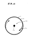
- Fig. 3 is a cross-sectional view along line A-A shown in Fig. 1.
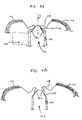
- Fig. 4A is an enlarged cross-sectional view showing one stage of deformation of a valve in the nozzle mechanism according to the present invention shown in Fig. 1.
- Fig. 4B is an enlarged cross-sectional view showing another stage of deformation of the valve in the nozzle mechanism according to the present invention shown in Fig. 1.
- Fig. 5A is an enlarged cross-sectional view showing one stage of deformation of a valve in the body portion of the aerosol dispenser shown in Fig. 1.
- Fig. 5B is an enlarged cross-sectional view showing another stage of deformation of the valve in the body portion of the aerosol dispenser shown in Fig. 1.
- Fig. 6A is a cross-sectional view showing a second embodiment of the nozzle mechanism according to the present invention.
- Fig. 6B is a cross-sectional view along line B-B shown in Fig. 6A.
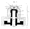
- Referring generally to Figs. 1 and 3, an aerosol-type dispenser system including a first exemplary embodiment of an aerosol tip or
nozzle mechanism 2 according to the present invention is indicated generally at 1. The first exemplary embodiment of theaerosol tip mechanism 2 includes aflexible nozzle portion 10 having anoutlet portion 108 and a fluid channel orswirling channel 104, arigid shaft 102 received within theflexible nozzle portion 10, and a rigidexternal housing 101 surrounding theflexible nozzle portion 10 and exposing theoutlet portion 108. Therigid shaft 102 interfaces the interior of theoutlet portion 108 to form a first normally-closedvalve 105, as well as to define a swirling chamber or collectingchamber 103 for liquid which has been channeled from a liquid reservoir, prior to being discharged via theoutlet portion 108 of theaerosol tip mechanism 2. - As shown in Figs. 1 and 3, for the first exemplary embodiment of the aerosol tip mechanism, the swirling channel or
fluid channel 104 includes gaps betweenwalls 1021a and 1021b circumferentially surrounding therigid shaft 102. Theswirling channel 104, which is described in further detail below, channels fluid into theswirling chamber 103. - A second exemplary embodiment of the aerosol tip or
nozzle mechanism 2 according to the present invention is shown in Figs. 6A and 6B. The second exemplary embodiment is substantially similar to the first exemplary embodiment, with one exception. In contrast to the first exemplary embodiment shown in Figs. 1 and 3, the second exemplary embodiment of the aerosol tip or nozzle mechanism does not includewalls 1021a and 1021b circumferentially surrounding therigid shaft 102. Accordingly, in the second embodiment shown in Figs. 6A and 6B, the swirlingchannel 104 is simply an integral part of the swirlingchamber 103. - As shown in Fig. 1, the first exemplary embodiment of the aerosol tip or
nozzle mechanism 2 according to the present invention is coupled to aflexible body portion 107 which as a substantially tubular shape and a wall thickness which decreases from the bottom of the body portion toward theflexible nozzle portion 10, along the elongated axis of symmetry of the body portion. Therigid shaft 102 received within theflexible nozzle portion 10 extends down into theflexible body portion 107 so that a second portion 102a of the rigid shaft interfaces theflexible body portion 107 to form a second normally-closedvalve 106. - Referring generally to Figs. 1 and 2, the
fluid communication path 201 of liquid from the liquid reservoir to theoutlet portion 108 successively traverses the first and second normally-closedvalves pump mechanism 110 of thedispenser system 1, acting in concert with a pump-body portion 111 of the dispenser system, channels the liquid from the liquid reservoir along thefluid communication path 201 by application of pressure. It should be noted that the nozzle mechanism according to the present invention is intended to be used in conjunction with a wide variety of liquid dispensing systems, one example of which is illustrated in applicant's commonly owned U.S. patent application Serial Number 08/534,609 filed on September 27, 1995, entitled "Fluid Pump Without Dead Volume," which is expressly incorporated herein by reference. Accordingly, it should be understood that thepump mechanism 110 and the pump-body portion 111 of the dispenser system shown in Figs. 1 and 2 are merely exemplary and generic representation of a wide variety of dispensing systems. - As shown in Figs. 1 and 2, the liquid from the liquid reservoir is initially channeled through a circumferential channel or groove 109 formed on the exterior of the second portion 102a of the rigid shaft. Once the pressure on the liquid in the fluid communication path reaches a threshold pressure sufficient to radially deform the flexible body portion 137, a
portion 501 of theflexible body portion 107 forming a lower segment of the second normally-closedvalve 106 is radially deformed by the liquid, thereby opening the second normally-closedvalve 106, as shown in Fig. 5A. As the liquid passes through the second normally-closedvalve 106 toward theflexible nozzle portion 10, sequential segments of theflexible body portion 107 forming the second normally-closedvalve 106 are radially deformed, as shown in Figs. 5A and 5B, until the liquid finally passes through theupper-most segment 502 of theflexible body portion 107 forming the second normally-closedvalve 106. - As shown in Figs. 5A and 5B, because the wall thickness of the
flexible body portion 107 decreases from thelower segment 501 to theupper segment 502 of the second normally-closedvalve 106, i.e., along the elongated axis of symmetry S of the nozzle mechanism, thelower segment 501 of thevalve 106 is substantially closed by the time the liquid has reached theupper segment 502. Because the energy required to open thelower segment 501 of thevalve 106 is greater than the energy required to open theupper segment 502, the liquid is naturally biased to maintain its forward movement through thesecond valve 106 in theflexible body portion 107 once thelower segment 501 has been opened. In this manner, the second normally-closedvalve 106 ensures liquid movement only in the direction towards theflexible nozzle portion 10. - Once the liquid in the
fluid communication path 201 has traversed the second normally-closedvalve 106, the liquid then enters thefluid channel 104 within theflexible nozzle portion 10 of the first embodiment of theaerosol tip mechanism 2, as shown in Figs. 1, 2 and 3. Thefluid channel 104, which defines a portion of thefluid communication path 201 between the liquid reservoir and the collectingchamber 103, is circumferentially positioned within the flexible nozzle portion, as shown in Fig. 3. The circumferentially positionedfluid channel 104 creates swirling action of the liquid, indicated in Fig. 3 by thedirectional arrow 301, as it is channeled into the swirlingchamber 103. For the second embodiment of the aerosol tip mechanism shown in Figs. 6A and 6B, the liquid directly enters the swirlingchamber 103 via thespace 601 once the liquid in thefluid communication path 201 has traversed the second normally-closedvalve 106. The swirling action of the liquid is maintained in the swirling chamber until the liquid is discharged via theoutlet portion 108, the mechanics of which discharging action is described in detail below. - Referring generally to Figs. 1, 4A and 4B, the liquid in the swirling chamber is discharged via the
outlet portion 108 when the liquid pressure reaches a threshold pressure sufficient to radially deform theoutlet portion 108 forming the first normally-closedvalve 105. As with the second normally-closedvalve 106 described above, the liquid movement through the first normally-closedvalve 105 involves sequential deformation of segments of theoutlet portion 108. As shown in Fig. 4A, aportion 401 of theoutlet portion 108 forming a lower segment of the first normally-closedvalve 105 is radially deformed by the liquid, thereby opening the first normally-closedvalve 105. As the liquid passes through the first normally-closedvalve 105 toward the tip of theoutlet portion 108, sequential segments of theoutlet portion 108 forming the first normally-closedvalve 105 are radially deformed, as shown in Figs. 4A and 4B, until the liquid finally passes through theupper-most segment 402 of theoutlet portion 108 forming the first normally-closedvalve 105. - As shown in Figs. 1, 4A and 4B, the wall thickness of the
outlet portion 108 decreases from thelower segment 401 towards theupper segment 402 of the first normally-closedvalve 105, i.e., along the elongated axis of symmetry S of the aerosol tip or nozzle mechanism. Due to this steady decrease in wall thickness, thelower segment 401 of thevalve 105 is substantially closed by the time the liquid has reached theupper segment 402, as shown in Figs. 4A and 4B. Because the energy required to open thelower segment 401 of thevalve 105 is greater than the energy requited to open theupper segment 402, the liquid is naturally biased to maintain its forward movement through thefirst valve 105 in theoutlet portion 108 once thelower segment 401 has been opened. Accordingly, thevalve 105 ensures liquid movement only in the direction towards the exterior tip of thenozzle portion 10. - During the discharge of liquid through the
outlet portion 108, the only segment of theflexible nozzle portion 10 which experiences deformation along the elongated axis of symmetry S of the aerosol tip or nozzle mechanism is theoutlet portion 108. The remaining segments of the flexible nozzle portion are prevented by therigid housing 101 from deformation along the elongated axis of symmetry S. Even theoutlet portion 108 experiences only minimal deformation along the axis S; the significant deformation is along the radial direction. Furthermore, theoutlet portion 108 does not exert a force along the axis S on therigid shaft 102, i.e., theoutlet portion 108 does not rub the rigid shaft during opening or closing of thefirst valve 105. Accordingly, because of the absence of any rubbing contact between theoutlet portion 108 and therigid shaft 102, the chances of contaminants entering the swirlingchamber 103 are minimized. - One advantage of the aerosol tip or nozzle mechanism according to the present invention is the above-described prevention of axial deformation of the
flexible nozzle portion 10 by therigid housing 101. Because theflexible nozzle portion 10, with the exception of theoutlet portion 108, experiences substantially no deformation along the elongated axis of symmetry S shown in Fig. 4A, the physical profile of thefluid channel 104, which induces swirling action of the liquid channeled into the swirlingchamber 103, is maintained during liquid discharge. An axial deformation of theflexible nozzle portion 10 along the direction of liquid discharge would deform thefluid channel 104, which in turn would prevent the swirling action from occurring. - In the above-described embodiment of the aerosol tip or nozzle mechanism according to the present invention, the
flexible nozzle portion 10, theflexible body portion 107 and the pump-body portion 111 may be made of any one of several materials well known in the art, including butadiene polyethylene styrene (KRATONTM), polyethylene, polyurethane or other plastic materials, thermoplastic elastomers or other elastic materials. KRATONTM is particularly well suited for this purpose because of its characteristic resistance to permanent deformation, or "creep," which typically occurs with passage of time. - Another advantage of the aerosol tip or nozzle mechanism according to the present invention is that the number of parts which constitute the nozzle mechanism and, in turn, the dispensing system which includes a pump mechanism in combination with the nozzle mechanism, is significantly reduced in comparison to conventional nozzle mechanisms. AS can be seen from Fig. 1, an aerosol-type dispensing system incorporating the nozzle mechanism according to the present invention can be made using only three discrete parts: the
rigid housing 101; an integral, flexible piece encompassing theflexible nozzle portion 10, theflexible body portion 107 and the pump-body portion 111; and therigid shaft 102 formed integrally with thepump mechanism 110. Because only three discrete parts are required, the cost and complexity of manufacturing an aerosol-type dispensing system is significantly reduced. - Yet another advantage of the aerosol tip or nozzle mechanism according to the present invention is that the first normally-closed, one-
way valve 105 with its decreasing wall thickness of theoutlet portion 108 substantially eliminates the possibility that liquid in the nozzle mechanism will come in contact with ambient air and subsequently return to the interior portion of the nozzle mechanism. Due to the decreasing wall thickness of theoutlet portion 108, the liquid is naturally biased to maintain its forward movement through thefirst valve 105 in theoutlet portion 108 once the thicker base portion of the valve has been opened. Accordingly, theoutlet portion 108 has a substantially zero "dead volume," i.e., a space in which liquid that has been previously exposed to ambient air can remain. - Still another advantage of the aerosol tip or nozzle mechanism according to the present invention is that the
outlet portion 108 does not rub therigid shaft 102 during opening or closing of thefirst valve 105. Accordingly, because of the absence of any rubbing contact between theoutlet portion 108 and therigid shaft 102, the chances of contaminants entering the swirlingchamber 103 are minimized. - Still another advantage of the aerosol tip or nozzle mechanism according to the present invention is the presence of multiple valves along the fluid communication path leading to the
outlet portion 108. In addition to the first normally-closed valve, the second normally-closed valve positioned along the fluid communication path between the liquid reservoir and the outlet adds further assurances that liquid in the liquid reservoir will not be contaminated by liquid that may have been accidentally exposed to ambient air and subsequently reintroduced into the nozzle mechanism. Because the first and second normally-closed valves are positioned along the fluid communication path to open sequentially, and hence asynchronously, during fluid communication leading to discharge through the outlet, failure of either one of the valves will not affect the integrity of the nozzle mechanism to prevent contamination of the liquid in the liquid reservoir. - While specific embodiments have been described above, it should be readily apparent to those of ordinary skill in the art that the above-described embodiments are exemplary in nature since certain changes may be made thereto without departing from the teachings of the invention, and the exemplary embodiments should not to be construed as limiting the scope of protection for the invention as set forth in the appended claims. For example, while the exemplary embodiment of the aerosol tip or nozzle mechanism according to the present invention has been described as having tubular-shaped outlet portion, other shapes, e.g., square or rectangle, may be used for the outlet portion.
Claims (28)
- A nozzle mechanism for an aerosol-type dispenser for dispensing liquid content by application of pressure, comprising:a flexible nozzle portion having an outlet portion for dispensing said liquid content, said outlet portion having a substantially tubular shape and having a wall thickness which decreases from a first point along a direction of elongated axis of symmetry of said nozzle mechanism toward a tip of the flexible nozzle portion;a rigid shaft received within the flexible nozzle portion and interfacing said outlet portion to form a first normally-closed valve, said rigid shaft and interior of said flexible nozzle portion defining a swirling chamber for said liquid content prior to expulsion via said outlet; anda rigid housing surrounding said flexible nozzle portion and exposing said outlet portion;wherein said liquid in said chamber is expelled via said first normally-closed valve upon reaching a threshold pressure sufficient to radially deform said outlet portion to open said first normally-closed valve, and wherein said rigid housing prevents deformation of said outlet portion along said axial direction during expulsion of said liquid content of said chamber via said outlet portion.
- The system according to claim 1, wherein said dispenser is in fluid communication with a liquid reservoir, and wherein said flexible nozzle portion further comprises a fluid channel defining a portion of a fluid communication path between said liquid reservoir and said swirling chamber, said channel inducing swirling action of liquid delivered to said swirling chamber.
- The system according to claim 2, wherein said fluid channel is positioned circumferentially in said flexible nozzle portion.
- The system according to claim 2, wherein said rigid housing further prevents axial deformation of said fluid channel.
- The system according to claim 3, wherein said rigid housing further prevents axial deformation of said fluid channel.
- The system according to claim 1, wherein said radial deformation of said outlet portion to open said first normally-closed valve comprises sequential deformation of portions of said outlet portion interfacing said rigid shaft along the axial direction, whereby an initial point of separation along the axial direction between said outlet portion and said rigid shaft is substantially closed when a final point of separation along the axial direction between said outlet portion and said rigid shaft is open.
- The system according to claim 2, wherein said radial deformation of said outlet portion to open said first normally-closed valve comprises sequential deformation of portions of said outlet portion interfacing said rigid shaft along the axial direction, whereby an initial point of separation along the axial direction between said outlet portion and said rigid shaft is substantially closed when a final point of separation along the axial direction between said outlet portion and said rigid shaft is open.
- The system according to claim 7, wherein said fluid channel is positioned circumferentially in said flexible nozzle portion.
- The system according to claim 8, wherein said rigid housing further prevents axial deformation of said fluid channel.
- The system according to claim 7, wherein said rigid housing further prevents axial deformation of said fluid channel.
- A fluid-dispensing mechanism for an aerosol-type dispenser in fluid communication with a liquid reservoir, comprising:a flexible nozzle portion having an outlet portion for dispensing liquid content of said dispenser, said outlet portion having a substantially tubular shape and a wall thickness which decreases from a first point along a direction of elongated axis of symmetry of said nozzle mechanism toward a tip of said flexible nozzle portion;a flexible body portion connected to said flexible nozzle portion, said body portion having a substantially tubular shape and a wall thickness which decreases from a second point along said axial direction toward said tip of said flexible nozzle portion;a rigid shaft member received within said flexible nozzle portion and said flexible body portion, a first portion of said rigid shaft member interfacing said outlet portion to form a first normally-closed valve, said first portion of said rigid shaft and interior of said flexible nozzle portion defining a swirling chamber for collecting liquid from said liquid reservoir prior to expulsion via said outlet portion, a second portion of said rigid shaft member interfacing said flexible body portion to form a second normally-closed valve; anda rigid housing surrounding said flexible nozzle portion and said flexible body portion and exposing said outlet portion;wherein a content of said fluid reservoir is channeled into said swirling chamber from said liquid reservoir via said second normally-closed valve upon application of sufficient pressure to open said second normally-closed valve, and wherein said liquid in said chamber is expelled via said first normally-closed valve upon reaching a pressure sufficient to radially deform said outlet portion to open said first normally-closed valve, and wherein said rigid housing prevents deformation of said outlet portion along said axial direction during expulsion of said liquid content of said swirling chamber via said outlet portion.
- The system according to claim 11, wherein said flexible nozzle portion further comprises a fluid channel defining a portion of a fluid communication path between said liquid reservoir and said swirling chamber, said fluid channel inducing swirling action of liquid delivered to said swirling chamber.
- The system according to claim 12, wherein said fluid channel is positioned circumferentially in said flexible nozzle portion.
- The system according to claim 12, wherein said rigid housing further prevents axial deformation of said fluid channel.
- The system according to claim 13, wherein said rigid housing further prevents axial deformation of said fluid channel.
- The system according to claim 11, wherein said radial deformation of said outlet portion to open said first normally-closed valve comprises sequential deformation of portions of said outlet portion interfacing said first portion of said rigid shaft member along the axial direction, whereby an initial point of separation along the axial direction between said outlet portion and said first portion of said rigid shaft member is substantially closed when a final point of separation along the axial direction between said outlet portion and said first portion of said rigid shaft member is open.
- The system according to claim 16, wherein said second normally-closed valve is opened upon application of sufficient pressure to radially deform said flexible body portion interfacing said second portion of said rigid shaft member, and wherein said radial deformation of said flexible body portion comprises sequential deformation of portions of said flexible body portion interfacing said second portion of said rigid shaft member, whereby an initial point of separation between said flexible body portion and said second portion of said rigid shaft member along the axial direction and away from said swirling chamber is substantially closed when a final point of separation between said flexible body portion and said second portion of said rigid shaft member along the axial direction and near said swirling chamber is open.
- The system according to claim 17, wherein said first and second normally-closed valves are opened asynchronously.
- The system according to claim 12, wherein said 2 radial deformation of said outlet portion to open said first normally-closed valve comprises sequential deformation of portions of said outlet portion interfacing said first portion of said rigid shaft member along the axial direction, whereby an initial point of separation along the axial direction between said outlet portion and said first portion of said rigid shaft member is substantially closed when a final point of separation along the axial direction between said outlet portion and said first portion of said rigid shaft member is open.
- The system according to claim 19, wherein said second normally-closed valve is opened upon application of sufficient pressure to radially deform said flexible body portion interfacing said second portion of said rigid shaft member, and wherein said radial deformation of said flexible body portion comprises sequential deformation of portions of said flexible body portion interfacing said second portion of said rigid shaft member, whereby an initial point of separation between said flexible body portion and said second portion of said rigid shaft member along the axial direction and away from said swirling chamber is substantially closed when a final point of separation between said flexible body portion and said second portion of said rigid shaft member along the axial direction and near said swirling chamber is open.
- The system according to claim 20, wherein said first and second normally-closed valves are opened asynchronously.
- The system according to claim 21, wherein said fluid channel is positioned circumferentially in said flexible nozzle portion.
- The system according to claim 22, wherein said rigid housing further prevents axial deformation of the fluid channel.
- The system according to claim 19, wherein said fluid channel is positioned circumferentially in said flexible nozzle portion.
- The system according to claim 24, wherein said rigid housing further prevents axial deformation of the fluid channel.
- A method of generating an aerosol-type fluid discharge from a dispenser in fluid communication with a liquid reservoir, said dispenser comprising a flexible nozzle portion having an outlet portion for dispensing said liquid content, said outlet portion having a wall thickness which decreases from a first point along a direction of elongated axis of symmetry of said nozzle mechanism toward a tip of the flexible nozzle portion, a first portion of a rigid shaft member received within the flexible nozzle portion and interfacing said outlet portion to form a first normally-closed valve, said first portion of said rigid shaft member and interior of said flexible nozzle portion defining a swirling chamber for said liquid content prior to expulsion via said outlet, said flexible nozzle portion further comprising a circumferentially positioned fluid channel defining a portion of a fluid communication path between said liquid reservoir and said swirling chamber, and a rigid housing surrounding said flexible nozzle portion and exposing said outlet portion, which method comprises:channeling liquid content of said liquid reservoir into said fluid communication path by application of pressure;channeling said liquid content into said swirling chamber via said circumferentially positioned fluid channel by application of pressure, thereby creating swirling movement of said liquid content in said swirling chamber; andexpelling said liquid content of said swirling chamber through said outlet via said first normally-closed valve by application of pressure sufficient to radially deform said outlet portion to open said first normally-closed valve while substantially preventing deformation of said outlet portion along the axial direction by relative urging of said rigid housing;wherein said radial deformation of said outlet portion to open said first normally-closed valve comprises sequential deformation of portions of said outlet portion interfacing said first portion of said rigid shaft member along the axial direction, whereby an initial point of separation along the axial direction between said outlet portion and said first portion of said rigid shaft member is substantially closed when a final point of separation along the axial direction between said outlet portion and said first portion of said rigid shaft member is open.
- The method according to claim 26, wherein said dispenser further comprises a flexible body portion connected to said flexible nozzle portion, said body portion having a wall thickness which decreases from a second point along said axial direction toward said tip of said flexible nozzle portion, and wherein said rigid shaft member further comprises a second portion interfacing said flexible body portion to form a second normally-closed valve in said fluid communication path, which method further comprises, prior to the step of channeling said liquid content into said swirling chamber via said circumferentially positioned fluid channel, the step of;channeling said liquid content through said second normally-closed valve into said circumferentially positioned fluid channel by application of pressure to radially deform said flexible body portion interfacing said second portion of said rigid shaft member to open said second normally-closed valve, wherein said radial deformation of said flexible body portion comprises sequential deformation of portions of said flexible body portion interfacing said second portion of said rigid shaft member, whereby an initial point of separation between said flexible body portion and said second portion of said rigid shaft member along the axial direction and away from said circumferentially positioned fluid channel is substantially closed when a final point of separation between said flexible body portion and said second portion of said rigid shaft member along the axial direction and near said circumferentially positioned fluid channel is open.
- The method according to claim 27, wherein said first and second normally-closed valves are opened asynchronously.
Applications Claiming Priority (2)
| Application Number | Priority Date | Filing Date | Title |
|---|---|---|---|
| US927221 | 1978-07-24 | ||
| US08/927,221 US5855322A (en) | 1997-09-10 | 1997-09-10 | System and method for one-way spray aerosol tip |
Publications (3)
| Publication Number | Publication Date |
|---|---|
| EP0906786A2 true EP0906786A2 (en) | 1999-04-07 |
| EP0906786A3 EP0906786A3 (en) | 2000-11-08 |
| EP0906786B1 EP0906786B1 (en) | 2003-12-03 |
Family
ID=25454418
Family Applications (1)
| Application Number | Title | Priority Date | Filing Date |
|---|---|---|---|
| EP98307246A Expired - Lifetime EP0906786B1 (en) | 1997-09-10 | 1998-09-08 | System and method for one-way spray/aerosol tip |
Country Status (12)
| Country | Link |
|---|---|
| US (2) | US5855322A (en) |
| EP (1) | EP0906786B1 (en) |
| JP (1) | JP4074949B2 (en) |
| KR (1) | KR100578444B1 (en) |
| AR (1) | AR015436A1 (en) |
| AT (1) | ATE255469T1 (en) |
| AU (1) | AU732591B2 (en) |
| BR (1) | BR9803401A (en) |
| CA (1) | CA2246294C (en) |
| DE (1) | DE69820189T2 (en) |
| ES (1) | ES2212228T3 (en) |
| HK (1) | HK1019315A1 (en) |
Families Citing this family (43)
| Publication number | Priority date | Publication date | Assignee | Title |
|---|---|---|---|---|
| FR2773784B1 (en) * | 1998-01-16 | 2000-03-24 | Valois Sa | SPRAY HEAD FOR A FLUID PRODUCT DISPENSER |
| DE19849687A1 (en) * | 1998-10-28 | 2000-05-04 | Valeo Auto Electric Gmbh | Nozzle element for a windscreen washer system of a vehicle |
| FR2792552B1 (en) * | 1999-04-20 | 2002-04-19 | Valois Sa | FLUID PRODUCT SPRAY HEAD COMPRISING AN IMPROVED SHUTTER |
| US6254579B1 (en) | 1999-11-08 | 2001-07-03 | Allergan Sales, Inc. | Multiple precision dose, preservative-free medication delivery system |
| US6302101B1 (en) * | 1999-12-14 | 2001-10-16 | Daniel Py | System and method for application of medicament into the nasal passage |
| US6398766B1 (en) * | 1999-12-27 | 2002-06-04 | Vista Innovations, Inc. | Eye wash system |
| US6524287B1 (en) | 2000-10-10 | 2003-02-25 | Advanced Medical Optics | Housing apparatus with rear activated return button for instilling a medication into an eye |
| US6533764B1 (en) | 2000-11-06 | 2003-03-18 | Allergan, Inc. | Twist housing apparatus for instilling a medication into an eye |
| US6415957B1 (en) * | 2000-11-27 | 2002-07-09 | S. C. Johnson & Son, Inc. | Apparatus for dispensing a heated post-foaming gel |
| US6543703B2 (en) * | 2000-12-26 | 2003-04-08 | William S. Blake | Flexible face non-clogging actuator assembly |
| US6506183B2 (en) | 2001-02-02 | 2003-01-14 | Advanced Medical Optics | One shot actuation housing apparatus for instilling a medication into an eye |
| GB2411609B (en) * | 2001-09-24 | 2006-02-22 | Py Daniel C | Method of controlling the particle size of aerosol discharged fluid |
| US6685109B2 (en) * | 2001-09-24 | 2004-02-03 | Daniel Py | System and method for a two piece spray nozzle |
| WO2003086945A2 (en) * | 2002-04-10 | 2003-10-23 | Disop-Nordic Holding Aps | Tube with self-closing mechanism for liquid container |
| US6609666B1 (en) * | 2002-07-24 | 2003-08-26 | William Sydney Blake | Unitary over-mold non-clog system with positive shutoff |
| DE10315934B4 (en) * | 2003-04-02 | 2005-08-04 | Ing. Erich Pfeiffer Gmbh | Discharge head for a dosing device |
| US8012136B2 (en) * | 2003-05-20 | 2011-09-06 | Optimyst Systems, Inc. | Ophthalmic fluid delivery device and method of operation |
| WO2004103478A1 (en) * | 2003-05-20 | 2004-12-02 | Collins James F | Ophthalmic drug delivery system |
| US20050056708A1 (en) * | 2003-09-12 | 2005-03-17 | Castillo Higareda Jose De Jesus | Apparatus for inducing turbulence in a fluid and method of manufacturing same |
| CN1901966A (en) * | 2003-11-14 | 2007-01-24 | 因斯蒂尔医学技术有限公司 | Delivery device and method of delivery |
| US7264142B2 (en) | 2004-01-27 | 2007-09-04 | Medical Instill Technologies, Inc. | Dispenser having variable-volume storage chamber and depressible one-way valve assembly for dispensing creams and other substances |
| CN102764719B (en) * | 2004-09-27 | 2016-10-05 | 因斯蒂尔医学技术有限公司 | For storing distributor and the filling fixing device thereof of distribution material |
| GB0515592D0 (en) | 2005-07-28 | 2005-09-07 | Glaxo Group Ltd | Nozzle for a nasal inhaler |
| FR2902675B1 (en) * | 2006-06-21 | 2008-09-12 | Lvmh Rech | FLUID PRODUCT DISTRIBUTION NOZZLE AND FLUID PRODUCT DISPENSING DEVICE COMPRISING SUCH A NOZZLE |
| US8132695B2 (en) | 2006-11-11 | 2012-03-13 | Medical Instill Technologies, Inc. | Multiple dose delivery device with manually depressible actuator and one-way valve for storing and dispensing substances, and related method |
| FR2912071B1 (en) * | 2007-02-05 | 2011-03-18 | De La Mer Laboratoire | SPRAY TIP, CONTAINER UNIDOSE SPRAYER AND UNIDOSE SPRAY KIT. |
| CN105776119B (en) * | 2007-05-16 | 2019-04-23 | 神秘制药公司 | Combination unit dose dispensing containers |
| US20090212133A1 (en) * | 2008-01-25 | 2009-08-27 | Collins Jr James F | Ophthalmic fluid delivery device and method of operation |
| FR2933680B1 (en) * | 2008-07-11 | 2013-01-18 | Valois Sa | FLUID PRODUCT DELIVERY PUMP |
| KR101029747B1 (en) | 2008-09-30 | 2011-04-19 | (주)프로템 | A Floating Nozzle of Dryer |
| JP5964826B2 (en) | 2010-07-15 | 2016-08-03 | アイノビア,インコーポレイティド | Drop generation device |
| EA201390121A8 (en) | 2010-07-15 | 2014-02-28 | Коринтиан Офтэлмик, Инк. | METHOD AND SYSTEM FOR PERFORMING REMOTE TREATMENT AND CONTROL |
| CA2805425C (en) | 2010-07-15 | 2019-07-23 | Corinthian Ophthalmic, Inc. | Ophthalmic drug delivery |
| US10154923B2 (en) | 2010-07-15 | 2018-12-18 | Eyenovia, Inc. | Drop generating device |
| WO2013090468A1 (en) | 2011-12-12 | 2013-06-20 | Corinthian Ophthalmic, Inc. | High modulus polymeric ejector mechanism, ejector device, and methods of use |
| US9415401B2 (en) | 2012-04-04 | 2016-08-16 | Alternative Packaging Solutions Llc | One turn actuated duration spray pump mechanism |
| DE102013215599B4 (en) * | 2013-08-07 | 2017-12-07 | Aptar Radolfzell Gmbh | Pumping device and dispenser for liquid or pasty media |
| BR112018011188B1 (en) * | 2015-12-04 | 2021-02-02 | Medspray Bv | spray device for spraying a fluidic micro-jet spray and spray nozzle body |
| DE102017104739A1 (en) | 2017-03-07 | 2018-09-13 | Ursatec Verpackung Gmbh | fluid dispenser |
| DE102017104740A1 (en) | 2017-03-07 | 2018-09-13 | Ursatec Verpackung Gmbh | fluid dispenser |
| KR20240034855A (en) | 2017-06-10 | 2024-03-14 | 아이노비아 인코포레이티드 | Methods and devices for handling a fluid and delivering the fluid to the eye |
| US11123220B1 (en) | 2017-11-21 | 2021-09-21 | CryoXcel, LLC | Gas delivery system for cryochamber |
| FR3078271B1 (en) * | 2018-02-27 | 2022-08-05 | Albea Services | DISTRIBUTION HEAD WITH STAGED WHIRLPOOL CHAMBER FOR A DISTRIBUTION SYSTEM |
Citations (6)
| Publication number | Priority date | Publication date | Assignee | Title |
|---|---|---|---|---|
| US3739952A (en) * | 1971-07-09 | 1973-06-19 | Gillette Co | Intermittent dispensing device |
| US4313569A (en) * | 1980-05-27 | 1982-02-02 | Ethyl Products Company | Fluid dispenser method and apparatus |
| US5314116A (en) * | 1992-01-21 | 1994-05-24 | Wade Manufacturing Co. | Pulsator for irrigation systems and the like |
| US5370318A (en) * | 1991-06-28 | 1994-12-06 | Glaxo Group Limited | Atomizing nozzle for producing a spray from a liquid under pressure |
| US5511538A (en) * | 1990-07-12 | 1996-04-30 | Habley Medical Technology Corporation | Super atomizing nonchlorinated fluorocarbon medication inhaler |
| US5518377A (en) * | 1994-08-11 | 1996-05-21 | Sofab | Vertical metering pump having piston biasing elastomeric gasket |
Family Cites Families (11)
| Publication number | Priority date | Publication date | Assignee | Title |
|---|---|---|---|---|
| DE3339180C2 (en) * | 1983-10-28 | 1993-10-14 | Pfeiffer Erich Gmbh & Co Kg | Discharge device for media |
| US4623337A (en) * | 1984-03-08 | 1986-11-18 | Alpha Group, Inc. | Liquid dispensing apparatus |
| US5133702A (en) * | 1987-11-06 | 1992-07-28 | O.P.T.I.C. | Ocular treatment apparatus |
| US4981479A (en) * | 1987-11-06 | 1991-01-01 | Py Daniel C | Ocular treatment apparatus |
| US4946452A (en) * | 1987-11-06 | 1990-08-07 | Py Daniel C | Ocular treatment apparatus |
| DE68902989T2 (en) * | 1988-12-20 | 1993-04-15 | Step Soc Tech Pulverisation | DEVICE FOR DISPENSING A LIQUID OR CREAM IN DROP SMALL VOLUME. |
| DE4041136C2 (en) * | 1990-12-21 | 1994-06-30 | Andris Raimund Gmbh & Co Kg | Dosing and spray pump for dispensing liquid, low-viscosity and pasty substances |
| ES2133378T3 (en) * | 1991-12-02 | 1999-09-16 | Py Daniel C | APPARATUS FOR APPLYING A MEDICATION TO THE EYE. |
| US5401259A (en) * | 1992-04-06 | 1995-03-28 | Py Daniel C | Cartridge for applying medicament to an eye |
| US5320845A (en) * | 1993-01-06 | 1994-06-14 | Py Daniel C | Apparatus for delivering multiple medicaments to an eye without premixing in the apparatus |
| US5358179A (en) * | 1993-08-18 | 1994-10-25 | The Procter & Gamble Company | Atomization systems for high viscosity products |
-
1997
- 1997-09-10 US US08/927,221 patent/US5855322A/en not_active Expired - Lifetime
-
1998
- 1998-09-01 CA CA002246294A patent/CA2246294C/en not_active Expired - Fee Related
- 1998-09-08 DE DE69820189T patent/DE69820189T2/en not_active Expired - Lifetime
- 1998-09-08 AR ARP980104470A patent/AR015436A1/en unknown
- 1998-09-08 EP EP98307246A patent/EP0906786B1/en not_active Expired - Lifetime
- 1998-09-08 AT AT98307246T patent/ATE255469T1/en not_active IP Right Cessation
- 1998-09-08 ES ES98307246T patent/ES2212228T3/en not_active Expired - Lifetime
- 1998-09-09 BR BR9803401-4A patent/BR9803401A/en not_active Application Discontinuation
- 1998-09-09 KR KR1019980037118A patent/KR100578444B1/en not_active IP Right Cessation
- 1998-09-09 AU AU83216/98A patent/AU732591B2/en not_active Ceased
- 1998-09-09 JP JP25572098A patent/JP4074949B2/en not_active Expired - Fee Related
- 1998-11-16 US US09/192,843 patent/US6053433A/en not_active Expired - Lifetime
-
1999
- 1999-10-07 HK HK99104419A patent/HK1019315A1/en not_active IP Right Cessation
Patent Citations (6)
| Publication number | Priority date | Publication date | Assignee | Title |
|---|---|---|---|---|
| US3739952A (en) * | 1971-07-09 | 1973-06-19 | Gillette Co | Intermittent dispensing device |
| US4313569A (en) * | 1980-05-27 | 1982-02-02 | Ethyl Products Company | Fluid dispenser method and apparatus |
| US5511538A (en) * | 1990-07-12 | 1996-04-30 | Habley Medical Technology Corporation | Super atomizing nonchlorinated fluorocarbon medication inhaler |
| US5370318A (en) * | 1991-06-28 | 1994-12-06 | Glaxo Group Limited | Atomizing nozzle for producing a spray from a liquid under pressure |
| US5314116A (en) * | 1992-01-21 | 1994-05-24 | Wade Manufacturing Co. | Pulsator for irrigation systems and the like |
| US5518377A (en) * | 1994-08-11 | 1996-05-21 | Sofab | Vertical metering pump having piston biasing elastomeric gasket |
Also Published As
| Publication number | Publication date |
|---|---|
| DE69820189T2 (en) | 2004-09-16 |
| HK1019315A1 (en) | 2000-02-03 |
| EP0906786A3 (en) | 2000-11-08 |
| KR100578444B1 (en) | 2006-07-25 |
| JPH11189282A (en) | 1999-07-13 |
| DE69820189D1 (en) | 2004-01-15 |
| EP0906786B1 (en) | 2003-12-03 |
| AR015436A1 (en) | 2001-05-02 |
| ES2212228T3 (en) | 2004-07-16 |
| US5855322A (en) | 1999-01-05 |
| AU732591B2 (en) | 2001-04-26 |
| US6053433A (en) | 2000-04-25 |
| KR19990029656A (en) | 1999-04-26 |
| BR9803401A (en) | 2001-03-20 |
| JP4074949B2 (en) | 2008-04-16 |
| AU8321698A (en) | 1999-03-25 |
| CA2246294C (en) | 2009-01-20 |
| CA2246294A1 (en) | 1999-03-10 |
| ATE255469T1 (en) | 2003-12-15 |
Similar Documents
| Publication | Publication Date | Title |
|---|---|---|
| US5855322A (en) | System and method for one-way spray aerosol tip | |
| EP1237607B1 (en) | System for application of medicament into the nasal passage | |
| AU730007B2 (en) | Dispenser for media | |
| JP3355459B2 (en) | Device for spraying or dispensing fluid | |
| US6516976B2 (en) | Dosing pump for liquid dispensers | |
| JPH06191571A (en) | Dispenser to distritube liquid, creamy or pasty substance | |
| CZ295103B6 (en) | Device of miniaturized construction for producing high pressure in a fluid, atomizer for spraying pressurized liquid and reciprocating pump device for producing high pressure in a fluid | |
| EP0998355B1 (en) | Push-button comprising a movable nozzle for dispensing pressurized fluids | |
| EP0754499A2 (en) | Atomized liquid dispenser | |
| GB2340477A (en) | Metering valve | |
| MXPA98007337A (en) | System and method for spray tip / spray of a p | |
| CA2593572C (en) | System and method for application of medicament into the nasal passage | |
| AU2002235223A1 (en) | Dosing pump for liquid dispensers | |
| NZ245498A (en) | Trigger-operated hand pump; pump chamber comprises a resilient flexible tube with a corrugated bellows section |
Legal Events
| Date | Code | Title | Description |
|---|---|---|---|
| PUAI | Public reference made under article 153(3) epc to a published international application that has entered the european phase |
Free format text: ORIGINAL CODE: 0009012 |
|
| AK | Designated contracting states |
Kind code of ref document: A2 Designated state(s): AT BE CH DE DK ES FR GB IE IT LI NL PT SE |
|
| AX | Request for extension of the european patent |
Free format text: AL;LT;LV;MK;RO;SI |
|
| PUAL | Search report despatched |
Free format text: ORIGINAL CODE: 0009013 |
|
| AK | Designated contracting states |
Kind code of ref document: A3 Designated state(s): AT BE CH CY DE DK ES FI FR GB GR IE IT LI LU MC NL PT SE |
|
| AX | Request for extension of the european patent |
Free format text: AL;LT;LV;MK;RO;SI |
|
| RIC1 | Information provided on ipc code assigned before grant |
Free format text: 7B 05B 11/00 A, 7B 05B 1/32 B, 7B 05B 1/34 B, 7B 65D 47/20 B |
|
| 17P | Request for examination filed |
Effective date: 20010411 |
|
| AKX | Designation fees paid |
Free format text: AT BE CH DE DK ES FR GB IE IT LI NL PT SE |
|
| 17Q | First examination report despatched |
Effective date: 20020508 |
|
| GRAH | Despatch of communication of intention to grant a patent |
Free format text: ORIGINAL CODE: EPIDOS IGRA |
|
| GRAS | Grant fee paid |
Free format text: ORIGINAL CODE: EPIDOSNIGR3 |
|
| GRAA | (expected) grant |
Free format text: ORIGINAL CODE: 0009210 |
|
| AK | Designated contracting states |
Kind code of ref document: B1 Designated state(s): AT BE CH DE DK ES FR GB IE IT LI NL PT SE |
|
| PG25 | Lapsed in a contracting state [announced via postgrant information from national office to epo] |
Ref country code: NL Free format text: LAPSE BECAUSE OF FAILURE TO SUBMIT A TRANSLATION OF THE DESCRIPTION OR TO PAY THE FEE WITHIN THE PRESCRIBED TIME-LIMIT Effective date: 20031203 Ref country code: LI Free format text: LAPSE BECAUSE OF FAILURE TO SUBMIT A TRANSLATION OF THE DESCRIPTION OR TO PAY THE FEE WITHIN THE PRESCRIBED TIME-LIMIT Effective date: 20031203 Ref country code: CH Free format text: LAPSE BECAUSE OF FAILURE TO SUBMIT A TRANSLATION OF THE DESCRIPTION OR TO PAY THE FEE WITHIN THE PRESCRIBED TIME-LIMIT Effective date: 20031203 Ref country code: AT Free format text: LAPSE BECAUSE OF FAILURE TO SUBMIT A TRANSLATION OF THE DESCRIPTION OR TO PAY THE FEE WITHIN THE PRESCRIBED TIME-LIMIT Effective date: 20031203 |
|
| REG | Reference to a national code |
Ref country code: GB Ref legal event code: FG4D |
|
| REG | Reference to a national code |
Ref country code: CH Ref legal event code: EP |
|
| REG | Reference to a national code |
Ref country code: IE Ref legal event code: FG4D |
|
| REF | Corresponds to: |
Ref document number: 69820189 Country of ref document: DE Date of ref document: 20040115 Kind code of ref document: P |
|
| PG25 | Lapsed in a contracting state [announced via postgrant information from national office to epo] |
Ref country code: DK Free format text: LAPSE BECAUSE OF FAILURE TO SUBMIT A TRANSLATION OF THE DESCRIPTION OR TO PAY THE FEE WITHIN THE PRESCRIBED TIME-LIMIT Effective date: 20040303 |
|
| REG | Reference to a national code |
Ref country code: SE Ref legal event code: TRGR |
|
| NLV1 | Nl: lapsed or annulled due to failure to fulfill the requirements of art. 29p and 29m of the patents act | ||
| REG | Reference to a national code |
Ref country code: CH Ref legal event code: PL |
|
| REG | Reference to a national code |
Ref country code: ES Ref legal event code: FG2A Ref document number: 2212228 Country of ref document: ES Kind code of ref document: T3 |
|
| PGFP | Annual fee paid to national office [announced via postgrant information from national office to epo] |
Ref country code: IE Payment date: 20040928 Year of fee payment: 7 |
|
| ET | Fr: translation filed | ||
| PLBE | No opposition filed within time limit |
Free format text: ORIGINAL CODE: 0009261 |
|
| STAA | Information on the status of an ep patent application or granted ep patent |
Free format text: STATUS: NO OPPOSITION FILED WITHIN TIME LIMIT |
|
| 26N | No opposition filed |
Effective date: 20040906 |
|
| PG25 | Lapsed in a contracting state [announced via postgrant information from national office to epo] |
Ref country code: IE Free format text: LAPSE BECAUSE OF NON-PAYMENT OF DUE FEES Effective date: 20050908 |
|
| REG | Reference to a national code |
Ref country code: IE Ref legal event code: MM4A |
|
| PG25 | Lapsed in a contracting state [announced via postgrant information from national office to epo] |
Ref country code: PT Free format text: LAPSE BECAUSE OF NON-PAYMENT OF DUE FEES Effective date: 20040503 |
|
| BERE | Be: lapsed |
Owner name: *PY DANIEL Effective date: 20100930 |
|
| PGFP | Annual fee paid to national office [announced via postgrant information from national office to epo] |
Ref country code: IT Payment date: 20110219 Year of fee payment: 13 |
|
| PG25 | Lapsed in a contracting state [announced via postgrant information from national office to epo] |
Ref country code: BE Free format text: LAPSE BECAUSE OF NON-PAYMENT OF DUE FEES Effective date: 20100930 |
|
| PGFP | Annual fee paid to national office [announced via postgrant information from national office to epo] |
Ref country code: ES Payment date: 20110128 Year of fee payment: 13 |
|
| PGFP | Annual fee paid to national office [announced via postgrant information from national office to epo] |
Ref country code: BE Payment date: 20110722 Year of fee payment: 13 |
|
| BERE | Be: lapsed |
Owner name: *PY DANIEL Effective date: 20110930 |
|
| PG25 | Lapsed in a contracting state [announced via postgrant information from national office to epo] |
Ref country code: IT Free format text: LAPSE BECAUSE OF NON-PAYMENT OF DUE FEES Effective date: 20110908 |
|
| PG25 | Lapsed in a contracting state [announced via postgrant information from national office to epo] |
Ref country code: BE Free format text: LAPSE BECAUSE OF NON-PAYMENT OF DUE FEES Effective date: 20110930 |
|
| REG | Reference to a national code |
Ref country code: ES Ref legal event code: FD2A Effective date: 20130530 |
|
| PG25 | Lapsed in a contracting state [announced via postgrant information from national office to epo] |
Ref country code: ES Free format text: LAPSE BECAUSE OF NON-PAYMENT OF DUE FEES Effective date: 20110909 |
|
| REG | Reference to a national code |
Ref country code: FR Ref legal event code: PLFP Year of fee payment: 19 |
|
| REG | Reference to a national code |
Ref country code: FR Ref legal event code: PLFP Year of fee payment: 20 |
|
| PGFP | Annual fee paid to national office [announced via postgrant information from national office to epo] |
Ref country code: DE Payment date: 20170905 Year of fee payment: 20 Ref country code: GB Payment date: 20170906 Year of fee payment: 20 Ref country code: FR Payment date: 20170810 Year of fee payment: 20 |
|
| PGFP | Annual fee paid to national office [announced via postgrant information from national office to epo] |
Ref country code: SE Payment date: 20170912 Year of fee payment: 20 |
|
| REG | Reference to a national code |
Ref country code: DE Ref legal event code: R071 Ref document number: 69820189 Country of ref document: DE |
|
| REG | Reference to a national code |
Ref country code: GB Ref legal event code: PE20 Expiry date: 20180907 |
|
| PG25 | Lapsed in a contracting state [announced via postgrant information from national office to epo] |
Ref country code: GB Free format text: LAPSE BECAUSE OF EXPIRATION OF PROTECTION Effective date: 20180907 |