EP0906829B1 - Ink-jet printer having a maintenance station assembly - Google Patents
Ink-jet printer having a maintenance station assembly Download PDFInfo
- Publication number
- EP0906829B1 EP0906829B1 EP98118356A EP98118356A EP0906829B1 EP 0906829 B1 EP0906829 B1 EP 0906829B1 EP 98118356 A EP98118356 A EP 98118356A EP 98118356 A EP98118356 A EP 98118356A EP 0906829 B1 EP0906829 B1 EP 0906829B1
- Authority
- EP
- European Patent Office
- Prior art keywords
- members
- camshaft
- wiping
- assembly station
- fitted
- Prior art date
- Legal status (The legal status is an assumption and is not a legal conclusion. Google has not performed a legal analysis and makes no representation as to the accuracy of the status listed.)
- Expired - Lifetime
Links
Images


Classifications
-
- B—PERFORMING OPERATIONS; TRANSPORTING
- B41—PRINTING; LINING MACHINES; TYPEWRITERS; STAMPS
- B41J—TYPEWRITERS; SELECTIVE PRINTING MECHANISMS, i.e. MECHANISMS PRINTING OTHERWISE THAN FROM A FORME; CORRECTION OF TYPOGRAPHICAL ERRORS
- B41J2/00—Typewriters or selective printing mechanisms characterised by the printing or marking process for which they are designed
- B41J2/005—Typewriters or selective printing mechanisms characterised by the printing or marking process for which they are designed characterised by bringing liquid or particles selectively into contact with a printing material
- B41J2/01—Ink jet
- B41J2/135—Nozzles
- B41J2/165—Preventing or detecting of nozzle clogging, e.g. cleaning, capping or moistening for nozzles
- B41J2/16517—Cleaning of print head nozzles
- B41J2/16535—Cleaning of print head nozzles using wiping constructions
- B41J2/16544—Constructions for the positioning of wipers
- B41J2/16547—Constructions for the positioning of wipers the wipers and caps or spittoons being on the same movable support
Landscapes
- Ink Jet (AREA)
Description
- This invention relates to an ink-jet printer comprising a chassis, a movable carriage bearing one or more printheads and suitable for being moved according to a direction of movement, and a maintenance assembly station according to the preamble of claim 1.
- In ink-jet printers, it is common practice to protect the ink emission nozzles of printheads, when they are in the idle position for a considerable length of time between printing periods, in order to prevent the ink from drying and clogging the nozzles.
- For this purpose, a cap is applied against the front plate of the nozzles and this maintains a certain degree of humidity.
- A maintaining assembly station with a camshaft for an ink-jet printer having more heads is known from EP-A-0 410 691. The station comprises, as movable members, four caps and four groups of wiping blades and associated cap arm and wiper support mounted transversely to the heads. The camshaft actuates the caps and the blades by means of two adjacent cams and cam followers connected to the cap arm and the wiper support and pivotable around independent axes parallel to the axis of the camshaft. This maintenance assembly station does not relate to components other than the caps and the wiping blades. Further its structure is rather cumbersome and not adapted to easily integrate other functional components of the station.
- U.S. patent no. 5,155,497 describes a maintenance assembly station for a printer with interchangeable printheads. This station comprises a support rotating at 180° about an axis parallel to the direction of movement of the carriage and upon which two caps are mounted in opposite positions by means of two slides which can be moved longitudinally along this direction of movement of the movable carriage. Upon detection of the type of printhead mounted on the carriage, the rotating support performs a rotation to put the slide and the cap that correspond to the head in position, and the carriage then moves the slide longitudinally in order to apply the cap against the nozzle-carrying plate.
- This maintenance assembly station is composed of a large number of parts and is difficult to construct. What is more, it cannot be integrated in existing printers and is not applicable on printers having two or more printheads mounted on the carriage at the same time.
- The object of this invention is to produce a printer having a maintenance assembly station that is very easy to build, works reliably, has a low cost price, is suitable for integration in existing printers and applicable on printers with one, two or more printheads. The invention is characterized to this end by the fact that said maintenance assembly station further comprises at least one suction member connected to the sealing members to produce a sucking effect therein, and wherein the camshaft is characterizing part of claim 1.
- With these characteristics, a printer is obtained having a maintenance assembly station that is very easy to build and thoroughly suited to the functions to be accomplished, that works precisely and reliably, and that has a low cost price. The maintenance assembly station is suitable for integration without difficulty in existing printers and can be applied on printers with one, two or more printheads due to the fact that numerous movable members can be activated with a complex, precise timing mechanism.
- To advantage, the maintenance assembly station comprises one or more sealing members, one or more wiping members, one or more cleaning members intended for removing the ink accumulated on the wiping members and at least one suction member connected to the sealing members to produce a sucking effect therein, all these members being fitted on the said module one after the other in the said direction and each activated by elements forming a cam integral with the said shaft.
- Accordingly, a maintenance assembly station is obtained that is particularly effective and of reliable operation, protecting one or more printheads simultaneously.
- A preferred embodiment is characterized by the fact that the maintenance assembly station comprises a module provided with a support constituting the body of the module wherein the said camshaft is fitted with an orientation parallel to the said direction of movement in a substantially central position, the said sealing, wiping and cleaning members each comprising a part fitted movably on the support, having a central aperture for the passage of the said camshaft and a portion intended for co-operating with the camshaft.
- The maintenance assembly station thus possesses a particularly compact build, with low overall dimensions, while at the same time permitting precision control of the maintenance functions.
- According to one favourable mode of construction of the invention, the active members of the camshaft are arranged so that a working cycle of the maintenance assembly station comprises the following steps:
- a) idle position : the sealing members are in an active position, the suction member is armed, the wiping and cleaning members are in an inactive position;
- b) the suction member is activated in the transition from the armed position to the non-armed position and a sucking effect is created in the sealing members;
- c) the sealing members are withdrawn and the wiping members are put in the active position for wiping the printheads;
- d) the suction member is rearmed, the cleaning members are put in the active position, while the wiping members are withdrawn and cleaned;
- e) the cleaning members are put in the inactive position;
- f) when the carriage is in position facing the maintenance assembly station, the sealing members are moved into the active position in order to restore the idle position a).
-
- These characteristics permit extremely precise and effective operation of the maintenance assembly station of the printer.
- Advantageously, the camshaft is made as one piece of a moulded, synthetic material.
- This gives a low cost price, while also ensuring precision control over the maintenance functions.
- Other advantages will become apparent from the characteristics set down in the associated claims and in the more detailed description of the invention provided below, with the aid of drawings representing one embodiment schematically and by way of a non-limiting example.
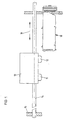
- Figure 1 is a schematic view of a part of the printer showing the maintenance assembly station.
- Figure 2 is a plan view of the maintenance assembly station.
- Figure 3 is a cross-section view according to the plane II-III of figure 2.
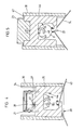
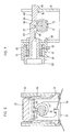
- Figures 4 to 7 are cross-section views according to the planes IV-IV, V-V, VI-VI and VII-VII of figure 3.
-
- The printer illustrated in figure 1 comprises a
carriage 10 provided with twoprintheads shaft 14 affixed to thechassis 15 of the printer and moves backwards and forwards along a document to be printed according to adirection 16. The printer possesses amaintenance assembly station 18, disposed to one side outside the printing zone. This station consists of a compact module serving the two printheads, ensuring that they are cleaned, and also that they are sealed when in the rest position in order to prevent the ink from drying in the nozzles of the printheads and the nozzles from becoming clogged. - With reference to the figures 2 and 3, the
maintenance assembly station 18 comprises two sealingmembers 20 in the form ofcaps 21 intended for covering the front part of the printheads, twowiping members 22 each comprising aflexible bib 23 intended for coming into contact with the front part of the heads and their nozzles in order to wipe the latter, twocleaning members 24 for thebibs 23 having ascraper 25 arranged so as to eliminate the ink accumulated on thebibs 23 and asuction member 26 intended for exercising a depression and a sucking effect on the nozzles of the printheads. All thesemembers support 30 constituting the body of the maintenance assembly station module. - They are disposed one after the other according to the
direction 16 and are all activated by asingle camshaft 31 connected by means of afriction coupling 32 to a drive motor not depicted. Thecamshaft 31 is fitted rotatingly on thesupport 30 of the module and arranged in an orientation parallel to thedirection 16 of movement of thecarriage 10. Theshaft 31 and its seven cams are made as a single piece, for instance by the injection moulding of a synthetic material. - The
maintenance assembly station 18 thus possesses twomaintenance assemblies wiping member 22, acleaning member 24 and a sealingmember 20 fitted one after the other in the saiddirection 16, thesuction member 26 being arranged between the twoassemblies - Each of the sealing members 20 (figure 4) comprises a
sliding part 35 fitted ingrooves 36 in thesupport 30. This slidingpart 35, in its upper part, has awall 37 intended for receiving thecap 21, made of a flexible elastomeric material and arranged to be applied tightly against the front part of one of the twoprintheads wall 37 with thecap 21 forms achamber 39 having anoutgoing end 40 connected by aflexible pipe 41 or 42 (fig. 2,3) to thesuction member 26. An intermediate portion of thesliding part 35 is provided with acentral aperture 44, allowing thecamshaft 31 to pass. Anintermediate edge 45 co-operates with the cam 55 of theshaft 31 and aspring 43 is arranged so as to urge theintermediate edge 45 against the cam 55. - In the position illustrated in figure 4, the
sliding part 35 is in the lower position. When theshaft 31 has turned by about 180°, thesliding part 35 is in the upper position, wherein theflexible cap 21 comes to rest against the face of the nozzles of one of theprintheads - With reference to figure 5, the
wiping members 22 comprise asliding part 46 arranged ingrooves 47 in thesupport 30. Theflexible bib 23 is affixed to the upper portion of this sliding part, while aspring 74 is arranged so as to urge anintermediate edge 49 of this slidingpart 46 against acam 48 of theshaft 31, which traverses thepart 46 thanks to acentral aperture 56. - In the position illustrated, the
wiping member 22 is in its upper position and theflexible bib 23 sweeps the front face of the printhead and the nozzles when the latter moves past in front of the wiping member. - The
cleaning members 24 depicted in figure 6 comprise apivoting part 50, provided with twopivots 51 engaging in apertures made in thesupport 30. The upper portion of this pivoting part is chamfered in order to constitute thescraper 25. In its central portion, thepivoting part 50 is provided with afinger 52 engaging in agroove 53 in the shape of a cam of theshaft 31 and aspring 54 is arranged so as to urge thisfinger 52 against one of the faces of this groove in order to define a very precise position of thepivoting part 50. Thecamshaft 31 traverses the pivotingpart 50 thanks to acentral aperture 73. In the position illustrated in figure 6, thescraper 25 is disengaged from thebib 22. Following a rotation of about 90° in a right-handed direction, thisscraper 25 is moved forward and gathers the ink deposited on thebib 23 while the latter is moved downwardly. The ink flows downwards thanks to the corrugated part of thescraper 25. - The sealing 20, wiping 22 and cleaning 24 members thus each consist of a part fitted movably on the
support 30, having acentral aperture camshaft 31 to pass and aportion camshaft 31. - With reference to figure 7, the suction member or pump 26 comprises a
cylinder 57 attached by threecatches 58 to thesupport 30 and apiston 59 slidingly fitted in thecylinder 57 in opposition to aspring 60 housed in achamber 61 of the cylinder. This chamber communicates through ends 62 with theflexible pipes members 20. Thepiston 59 is provided with two activatingpins first pin 63 is shorter and is arranged between twobranches 65 of thesecond pin 64. Thisfirst pin 63 comprises astep 66 suitable for co-operating with alip 67 of thecamshaft 31. - The
second pin 64 is longer and flexible and comprises anend part 68 connected to the twobranches 65 and is provided with twoteeth outer tooth 69 co-operates with the wall of thesupport 30 to maintain thepiston 59 in this position in opposition to the effect of thespring 60. When theshaft 31 turns in a right-handed direction, thepiston 59 is driven to the right by thelip 67 in abutment against thestep 66. The second,resilient pin 64 can then, by itssecond tooth 70, fasten onto thesupport 30, and the pump is then in the armed position. - In a more forward position of the
camshaft 31, by rotation through an angle of about 180°, aprotrusion 72 of the latter lifts thesecond pin 64, which triggers the partial relaxation of thespring 60 and the displacement of thepiston 59 to the left until the first,outer tooth 69, protruding more than thesecond tooth 70, fastens onto thesupport 30. During this movement, the volume of thechamber 61 is suddenly increased, causing a sucking effect in thechambers 39 of the sealingmembers 20. Thesuction member 26 can thus exert a depression on the nozzles of the printheads, which leads to there being only a small amount of ink on the face of the nozzles, permitting a priming of the latter and promoting the cleaning of the front face of theprintheads bibs 23. - The active elements of the
camshaft 31 are arranged in such a way that the complete operating cycle of the maintenance assembly stations controlled by thecamshaft 31 takes place as follows: - a) idle position: the
caps 21 are in the upper position, thesuction member 26 is armed, thebibs 23 and thescrapers 25 are in a disengaged position, thecarriage 10 is motionless in front of themaintenance assembly station 18; - b) the
suction member 26 is activated, a sucking effect is produced in thechambers 39 of the caps, the nozzles are primed by depression; - c) the
caps 21 move downwards and thebibs 23 move up to the active position, thecarriage 10 is moved towards the printing zone; as it passes, the front part of the printheads and the nozzles are cleaned by thebibs 23; - d) the
suction member 26 is rearmed; thescrapers 25 come into contact with thebibs 23 so that they can be cleaned during their downward movement; - e) the
bibs 23 reach the lower position and thescrapers 25 are disengaged; the carriage is free to effect its backward and forward movement; - f) when the
carriage 10 is in position facing themaintenance assembly station 18, thecaps 21 are then fitted so as to be applied against theprintheads -
- It will be obvious that the form of embodiment described is not in any way restrictive and that all the changes desired may be made to it without departing from the scope as defined in claim 1. In particular, the maintenance assembly station could be envisaged for one or three or more printheads borne by the carriage and will then comprise one or three or more maintenance assemblies.
- The cams provided on the
shaft 31 could be adapted differently, for example, to produce a wiping on the outbound and return movement of the carriage. The scraper could then be adapted to treat two faces of the bibs. - Other functions, such as a humidification of the front face of the heads, could be integrated in the maintenance assembly station and driven by rotation of the camshaft.
Claims (10)
- Ink-jet printer comprising a chassis (15), a movable carriage (10) bearing one or more printheads (11, 12) and suitable for being moved according to a direction of movement (16) and a maintenance assembly station (18) having, as movable members, one or more sealing members (20) suitable for being applied against the one or more printheads (11, 12) and one or more wiping members (22) for wiping the ink off the printheads (11, 12), and comprising a camshaft (31) for activating the sealing members (20) and the wiping members (22), said printer being characterized in that
the maintenance assembly station (18) further comprises other movable members including at least one suction member (26) connected to the sealing members (20) to produce a sucking effect therein, and wherein
said camshaft (31) is fitted rotatingly with its axis oriented substantially parallel to the direction of movement (16) of the carriage and is arranged so as to activate all the movable members (20, 22, 26) of the maintenance assembly station including said at least one suction member (26); and
all these members are fitted one after the other in said direction (16) and each activated by elements forming cams (48, 55, 67, 72) integral with said camshaft (31). - Printer according to claim 1, characterized in that the maintenance assembly station (18) further comprises, as movable member, one or more cleaning members (24) intended for removing the ink accumulated on the wiping members (22) and wherein the said elements forming cams comprise a further element forming cam (53) integral with said camshaft (31).
- Printer according to claim 2, characterized in that the maintenance assembly station (18) comprises a module provided with a support (30) constituting the body of the module, wherein said camshaft (31) is fitted with an orientation parallel to said direction of movement (16) in a substantially central position, said sealing (20), wiping (22) and cleaning (24) members each comprising a part (35, 46, 50) fitted movably on the support (30), having a central aperture (44, 56, 73) to allow the said camshaft (31) to pass and a portion (45, 49, 52) intended for co-operating with the camshaft (31).
- Printer according to claim 2 or 3, characterized in that the maintenance assembly station (18) comprises two maintenance assemblies (27, 28) each consisting of a wiping member (22), a cleaning member (24) and a sealing member (20) fitted one after the other in said direction (16), the suction member (26) being arranged between the two assemblies (27, 28).
- Printer according to one of the claims 3 or 4, characterized in that the sealing member (20) comprises a part (35) fitted slidingly on said support (30) in a direction perpendicular to the direction of movement (16), provided at its upper end with a cap (21) made of a flexible material and having a central aperture (44) enabling the passage of the camshaft (31) which co-operates with an intermediate portion (45) of this sliding part (35) urged by a spring (43) against the camshaft (31).
- Printer according to any of the claims 3 to 5, characterized in that the wiping member (22) comprises a part (46) fitted slidingly on the said support (30) in a direction perpendicular to the direction of movement (16), provided at its upper end with a flexible bib (23) and having a central aperture (56) enabling the passage of the camshaft (31) which co-operates with an intermediate portion (49) of this sliding part (46) urged by a spring (74) against the camshaft (31).
- Printer according to any of the claims from 3 to 6, characterized in that the cleaning member (24) comprises a part (50) fitted pivotingly by its lower end on said support (30), provided at its upper end with a scraper (25) and having a central aperture (73) enabling the passage of the camshaft (31) which has a groove (53) forming a cam wherein a finger (52) of the pivoting part (50) is engaged.
- Printer according to the claims 3 to 7, characterized in that the suction member (26) comprises a cylinder (57) affixed to the support (30) and a piston (59) fitted slidingly in a direction perpendicular to the direction of movement (16), the piston being integral with an activating pin (63) arranged so as to cooperate with a nozzle (67) of the camshaft to move the piston (59) from a non-armed position to an armed position in opposition to the effect of a spring (60), the piston (59) comprising retaining means (65, 68, 70) for retaining the piston (59) in an armed position and capable of co-operating with a portion (72) of the camshaft (31) to release the piston (59) in order to create the sucking effect in the sealing members (20).
- Printer according to any one of the claims from 2 to 8, characterized in that the active elements of the camshaft (31) are arranged so that an operating cycle of the maintenance assembly station (18) comprises the following steps:a) idle position: the sealing members (20) are in an active position, the suction member (26) is armed, the wiping members (22) and cleaning members (24) are in an inactive position;b) the suction member (26) is activated in the transition from the armed position to the non-armed position and a sucking effect is created in the sealing members (20);c) the sealing members (20) are withdrawn and the wiping members (22) are put in the active position for wiping the printheads (11, 12);d) the suction member (26) is rearmed, the cleaning members (24) are put in the active position, while the wiping members (22) are withdrawn and cleaned;e) the cleaning members (24) are put in the inactive position;f) when the carriage (10) is in position facing the maintenance assembly station (18), the sealing members (20) are moved into the active position in order to restore the idle position a).
- Printer according to one of the previous claims, characterized in that the camshaft (31) is made as one piece of a moulded synthetic material.
Applications Claiming Priority (3)
| Application Number | Priority Date | Filing Date | Title |
|---|---|---|---|
| CH02307/97A CH691766A5 (en) | 1997-10-02 | 1997-10-02 | An ink jet with maintenance station. |
| CH2307/97 | 1997-10-02 | ||
| CH230797 | 1997-10-02 |
Publications (3)
| Publication Number | Publication Date |
|---|---|
| EP0906829A2 EP0906829A2 (en) | 1999-04-07 |
| EP0906829A3 EP0906829A3 (en) | 1999-07-21 |
| EP0906829B1 true EP0906829B1 (en) | 2003-11-12 |
Family
ID=4230746
Family Applications (1)
| Application Number | Title | Priority Date | Filing Date |
|---|---|---|---|
| EP98118356A Expired - Lifetime EP0906829B1 (en) | 1997-10-02 | 1998-09-28 | Ink-jet printer having a maintenance station assembly |
Country Status (4)
| Country | Link |
|---|---|
| US (1) | US6139129A (en) |
| EP (1) | EP0906829B1 (en) |
| CH (1) | CH691766A5 (en) |
| DE (1) | DE69819650T2 (en) |
Families Citing this family (9)
| Publication number | Priority date | Publication date | Assignee | Title |
|---|---|---|---|---|
| US6416161B1 (en) * | 2000-06-16 | 2002-07-09 | Xerox Corporation | Wiper blade mechanism for ink jet printers |
| US6402293B1 (en) * | 2000-06-16 | 2002-06-11 | Xerox Corp. | Vacuum accumulator and ink manifold |
| US6398338B1 (en) * | 2000-06-16 | 2002-06-04 | Xerox Corporation | Cam-actuated lever capping arm |
| US6398339B1 (en) * | 2000-06-16 | 2002-06-04 | Xerox Corp. | Time and drive systems for a multifunction ink jet printer maintenance station |
| US6595619B2 (en) * | 2001-10-30 | 2003-07-22 | Hewlett-Packard Development Company, L.P. | Printing mechanism service station for a printbar assembly |
| US6592200B2 (en) * | 2001-10-30 | 2003-07-15 | Hewlett-Packard Development Company, L.P. | Integrated print module and servicing assembly |
| US6773088B2 (en) * | 2002-11-15 | 2004-08-10 | Lexmark International, Inc. | Double lipped printhead maintenance cap |
| US6817695B1 (en) | 2003-06-03 | 2004-11-16 | Lexmark International, Inc. | Printhead capping assembly |
| US7021741B2 (en) * | 2003-11-21 | 2006-04-04 | Lexmark International, Inc. | Printhead cap assembly for an ink jet printer |
Family Cites Families (9)
| Publication number | Priority date | Publication date | Assignee | Title |
|---|---|---|---|---|
| KR940010881B1 (en) * | 1988-10-07 | 1994-11-19 | 캐논 가부시끼가이샤 | Recording apparatus |
| JPH0326546U (en) * | 1989-07-25 | 1991-03-18 | ||
| EP0480302B1 (en) * | 1990-10-03 | 1996-05-01 | Canon Kabushiki Kaisha | Ink jet recording apparatus |
| JP2872431B2 (en) * | 1991-04-22 | 1999-03-17 | キヤノン株式会社 | Ink jet recording device |
| US5155497A (en) * | 1991-07-30 | 1992-10-13 | Hewlett-Packard Company | Service station for ink-jet printer |
| US5339102A (en) * | 1992-11-12 | 1994-08-16 | Xerox Corporation | Capping carriage for ink jet printer maintenance station |
| US5712668A (en) * | 1994-03-25 | 1998-01-27 | Hewlett-Packard Company | Rotary Multi-ridge capping system for inkjet printheads |
| KR200151933Y1 (en) * | 1996-04-08 | 1999-07-15 | 윤종용 | Service station apparatus of inkjet printer |
| JP3704820B2 (en) * | 1996-07-16 | 2005-10-12 | ブラザー工業株式会社 | Ink-jet head cap means |
-
1997
- 1997-10-02 CH CH02307/97A patent/CH691766A5/en not_active IP Right Cessation
-
1998
- 1998-09-28 DE DE69819650T patent/DE69819650T2/en not_active Expired - Lifetime
- 1998-09-28 EP EP98118356A patent/EP0906829B1/en not_active Expired - Lifetime
- 1998-09-29 US US09/162,505 patent/US6139129A/en not_active Expired - Lifetime
Also Published As
| Publication number | Publication date |
|---|---|
| DE69819650D1 (en) | 2003-12-18 |
| EP0906829A2 (en) | 1999-04-07 |
| EP0906829A3 (en) | 1999-07-21 |
| DE69819650T2 (en) | 2004-09-30 |
| US6139129A (en) | 2000-10-31 |
| CH691766A5 (en) | 2001-10-15 |
Similar Documents
| Publication | Publication Date | Title |
|---|---|---|
| KR101309791B1 (en) | An image forming apparatus and method for driving the same | |
| JP4939620B2 (en) | Service station and inkjet printer | |
| JP3595370B2 (en) | Printer head wiping structure for inkjet printer | |
| EP0856404A1 (en) | Fiber cleaning system for inkjet printhead wipers | |
| JP5955053B2 (en) | Recording apparatus and recording apparatus control method | |
| CN103370202B (en) | Inkjet-printing device | |
| EP0906829B1 (en) | Ink-jet printer having a maintenance station assembly | |
| JP5455575B2 (en) | Recording device | |
| JPH05201013A (en) | Wiper device for printing head of ink jet printer | |
| JP2005138317A (en) | Discharge recovery device and inkjet recording apparatus | |
| JPH0671904A (en) | Color ink-jet recording apparatus | |
| US6702423B2 (en) | Cleaning device for inkjet printing head, cleaning method for inkjet printing head, inkjet recording apparatus, and wiper | |
| JP4217435B2 (en) | Inkjet recording device | |
| JPS62251146A (en) | Ink jet recorder | |
| JP2618007B2 (en) | Ink jet recording device | |
| JPH09141884A (en) | Ink jet printer | |
| JP2000177113A (en) | Ink-jet recording apparatus | |
| JP3246983B2 (en) | Discharge recovery device and ink jet recording device equipped with the same | |
| JP3704820B2 (en) | Ink-jet head cap means | |
| JP2002240308A (en) | Recording head unit and ink jet recorder | |
| JP4635794B2 (en) | Inkjet recording device | |
| JPH07223320A (en) | Ink-jet printer | |
| JP4174273B2 (en) | Inkjet recording device | |
| JP4642184B2 (en) | Inkjet recording device | |
| JP2001347679A (en) | Ink jet recorder |
Legal Events
| Date | Code | Title | Description |
|---|---|---|---|
| PUAI | Public reference made under article 153(3) epc to a published international application that has entered the european phase |
Free format text: ORIGINAL CODE: 0009012 |
|
| AK | Designated contracting states |
Kind code of ref document: A2 Designated state(s): DE FR GB IT |
|
| AX | Request for extension of the european patent |
Free format text: AL;LT;LV;MK;RO;SI |
|
| PUAL | Search report despatched |
Free format text: ORIGINAL CODE: 0009013 |
|
| AK | Designated contracting states |
Kind code of ref document: A3 Designated state(s): AT BE CH CY DE DK ES FI FR GB GR IE IT LI LU MC NL PT SE |
|
| AX | Request for extension of the european patent |
Free format text: AL;LT;LV;MK;RO;SI |
|
| 17P | Request for examination filed |
Effective date: 19991214 |
|
| AKX | Designation fees paid |
Free format text: AT BE CH DE DK ES FI FR GB GR IE IT LI LU MC NL PT SE |
|
| RBV | Designated contracting states (corrected) |
Designated state(s): DE FR GB IT |
|
| RAP1 | Party data changed (applicant data changed or rights of an application transferred) |
Owner name: OLIVETTI TECNOST S.P.A. |
|
| 17Q | First examination report despatched |
Effective date: 20020514 |
|
| GRAH | Despatch of communication of intention to grant a patent |
Free format text: ORIGINAL CODE: EPIDOS IGRA |
|
| GRAS | Grant fee paid |
Free format text: ORIGINAL CODE: EPIDOSNIGR3 |
|
| GRAA | (expected) grant |
Free format text: ORIGINAL CODE: 0009210 |
|
| AK | Designated contracting states |
Kind code of ref document: B1 Designated state(s): DE FR GB IT |
|
| REG | Reference to a national code |
Ref country code: GB Ref legal event code: FG4D |
|
| REF | Corresponds to: |
Ref document number: 69819650 Country of ref document: DE Date of ref document: 20031218 Kind code of ref document: P |
|
| ET | Fr: translation filed | ||
| PLBE | No opposition filed within time limit |
Free format text: ORIGINAL CODE: 0009261 |
|
| STAA | Information on the status of an ep patent application or granted ep patent |
Free format text: STATUS: NO OPPOSITION FILED WITHIN TIME LIMIT |
|
| 26N | No opposition filed |
Effective date: 20040813 |
|
| PGFP | Annual fee paid to national office [announced via postgrant information from national office to epo] |
Ref country code: GB Payment date: 20140929 Year of fee payment: 17 |
|
| PGFP | Annual fee paid to national office [announced via postgrant information from national office to epo] |
Ref country code: DE Payment date: 20140929 Year of fee payment: 17 |
|
| REG | Reference to a national code |
Ref country code: DE Ref legal event code: R082 Ref document number: 69819650 Country of ref document: DE Representative=s name: WEICKMANN & WEICKMANN PATENTANWAELTE - RECHTSA, DE Ref country code: DE Ref legal event code: R082 Ref document number: 69819650 Country of ref document: DE Representative=s name: PATENTANWAELTE WEICKMANN & WEICKMANN, DE |
|
| REG | Reference to a national code |
Ref country code: FR Ref legal event code: PLFP Year of fee payment: 18 |
|
| PGFP | Annual fee paid to national office [announced via postgrant information from national office to epo] |
Ref country code: FR Payment date: 20150917 Year of fee payment: 18 |
|
| PGFP | Annual fee paid to national office [announced via postgrant information from national office to epo] |
Ref country code: IT Payment date: 20150923 Year of fee payment: 18 |
|
| REG | Reference to a national code |
Ref country code: DE Ref legal event code: R119 Ref document number: 69819650 Country of ref document: DE |
|
| GBPC | Gb: european patent ceased through non-payment of renewal fee |
Effective date: 20150928 |
|
| PG25 | Lapsed in a contracting state [announced via postgrant information from national office to epo] |
Ref country code: GB Free format text: LAPSE BECAUSE OF NON-PAYMENT OF DUE FEES Effective date: 20150928 Ref country code: DE Free format text: LAPSE BECAUSE OF NON-PAYMENT OF DUE FEES Effective date: 20160401 |
|
| REG | Reference to a national code |
Ref country code: FR Ref legal event code: ST Effective date: 20170531 |
|
| PG25 | Lapsed in a contracting state [announced via postgrant information from national office to epo] |
Ref country code: FR Free format text: LAPSE BECAUSE OF NON-PAYMENT OF DUE FEES Effective date: 20160930 |
|
| PG25 | Lapsed in a contracting state [announced via postgrant information from national office to epo] |
Ref country code: IT Free format text: LAPSE BECAUSE OF NON-PAYMENT OF DUE FEES Effective date: 20160928 |