EP0906859A1 - Braking system for vehicles - Google Patents
Braking system for vehicles Download PDFInfo
- Publication number
- EP0906859A1 EP0906859A1 EP98116489A EP98116489A EP0906859A1 EP 0906859 A1 EP0906859 A1 EP 0906859A1 EP 98116489 A EP98116489 A EP 98116489A EP 98116489 A EP98116489 A EP 98116489A EP 0906859 A1 EP0906859 A1 EP 0906859A1
- Authority
- EP
- European Patent Office
- Prior art keywords
- brake
- pedal
- deceleration
- wheel brakes
- pressure
- Prior art date
- Legal status (The legal status is an assumption and is not a legal conclusion. Google has not performed a legal analysis and makes no representation as to the accuracy of the status listed.)
- Granted
Links
Images

Classifications
-
- B—PERFORMING OPERATIONS; TRANSPORTING
- B60—VEHICLES IN GENERAL
- B60T—VEHICLE BRAKE CONTROL SYSTEMS OR PARTS THEREOF; BRAKE CONTROL SYSTEMS OR PARTS THEREOF, IN GENERAL; ARRANGEMENT OF BRAKING ELEMENTS ON VEHICLES IN GENERAL; PORTABLE DEVICES FOR PREVENTING UNWANTED MOVEMENT OF VEHICLES; VEHICLE MODIFICATIONS TO FACILITATE COOLING OF BRAKES
- B60T8/00—Arrangements for adjusting wheel-braking force to meet varying vehicular or ground-surface conditions, e.g. limiting or varying distribution of braking force
- B60T8/32—Arrangements for adjusting wheel-braking force to meet varying vehicular or ground-surface conditions, e.g. limiting or varying distribution of braking force responsive to a speed condition, e.g. acceleration or deceleration
- B60T8/34—Arrangements for adjusting wheel-braking force to meet varying vehicular or ground-surface conditions, e.g. limiting or varying distribution of braking force responsive to a speed condition, e.g. acceleration or deceleration having a fluid pressure regulator responsive to a speed condition
- B60T8/44—Arrangements for adjusting wheel-braking force to meet varying vehicular or ground-surface conditions, e.g. limiting or varying distribution of braking force responsive to a speed condition, e.g. acceleration or deceleration having a fluid pressure regulator responsive to a speed condition co-operating with a power-assist booster means associated with a master cylinder for controlling the release and reapplication of brake pressure through an interaction with the power assist device, i.e. open systems
- B60T8/441—Arrangements for adjusting wheel-braking force to meet varying vehicular or ground-surface conditions, e.g. limiting or varying distribution of braking force responsive to a speed condition, e.g. acceleration or deceleration having a fluid pressure regulator responsive to a speed condition co-operating with a power-assist booster means associated with a master cylinder for controlling the release and reapplication of brake pressure through an interaction with the power assist device, i.e. open systems using hydraulic boosters
- B60T8/442—Arrangements for adjusting wheel-braking force to meet varying vehicular or ground-surface conditions, e.g. limiting or varying distribution of braking force responsive to a speed condition, e.g. acceleration or deceleration having a fluid pressure regulator responsive to a speed condition co-operating with a power-assist booster means associated with a master cylinder for controlling the release and reapplication of brake pressure through an interaction with the power assist device, i.e. open systems using hydraulic boosters the booster being a fluid return pump, e.g. in combination with a brake pedal force booster
-
- B—PERFORMING OPERATIONS; TRANSPORTING
- B60—VEHICLES IN GENERAL
- B60T—VEHICLE BRAKE CONTROL SYSTEMS OR PARTS THEREOF; BRAKE CONTROL SYSTEMS OR PARTS THEREOF, IN GENERAL; ARRANGEMENT OF BRAKING ELEMENTS ON VEHICLES IN GENERAL; PORTABLE DEVICES FOR PREVENTING UNWANTED MOVEMENT OF VEHICLES; VEHICLE MODIFICATIONS TO FACILITATE COOLING OF BRAKES
- B60T13/00—Transmitting braking action from initiating means to ultimate brake actuator with power assistance or drive; Brake systems incorporating such transmitting means, e.g. air-pressure brake systems
- B60T13/10—Transmitting braking action from initiating means to ultimate brake actuator with power assistance or drive; Brake systems incorporating such transmitting means, e.g. air-pressure brake systems with fluid assistance, drive, or release
- B60T13/66—Electrical control in fluid-pressure brake systems
- B60T13/662—Electrical control in fluid-pressure brake systems characterised by specified functions of the control system components
-
- B—PERFORMING OPERATIONS; TRANSPORTING
- B60—VEHICLES IN GENERAL
- B60T—VEHICLE BRAKE CONTROL SYSTEMS OR PARTS THEREOF; BRAKE CONTROL SYSTEMS OR PARTS THEREOF, IN GENERAL; ARRANGEMENT OF BRAKING ELEMENTS ON VEHICLES IN GENERAL; PORTABLE DEVICES FOR PREVENTING UNWANTED MOVEMENT OF VEHICLES; VEHICLE MODIFICATIONS TO FACILITATE COOLING OF BRAKES
- B60T13/00—Transmitting braking action from initiating means to ultimate brake actuator with power assistance or drive; Brake systems incorporating such transmitting means, e.g. air-pressure brake systems
- B60T13/10—Transmitting braking action from initiating means to ultimate brake actuator with power assistance or drive; Brake systems incorporating such transmitting means, e.g. air-pressure brake systems with fluid assistance, drive, or release
- B60T13/66—Electrical control in fluid-pressure brake systems
- B60T13/72—Electrical control in fluid-pressure brake systems in vacuum systems or vacuum booster units
-
- B—PERFORMING OPERATIONS; TRANSPORTING
- B60—VEHICLES IN GENERAL
- B60T—VEHICLE BRAKE CONTROL SYSTEMS OR PARTS THEREOF; BRAKE CONTROL SYSTEMS OR PARTS THEREOF, IN GENERAL; ARRANGEMENT OF BRAKING ELEMENTS ON VEHICLES IN GENERAL; PORTABLE DEVICES FOR PREVENTING UNWANTED MOVEMENT OF VEHICLES; VEHICLE MODIFICATIONS TO FACILITATE COOLING OF BRAKES
- B60T7/00—Brake-action initiating means
- B60T7/12—Brake-action initiating means for automatic initiation; for initiation not subject to will of driver or passenger
-
- B—PERFORMING OPERATIONS; TRANSPORTING
- B60—VEHICLES IN GENERAL
- B60T—VEHICLE BRAKE CONTROL SYSTEMS OR PARTS THEREOF; BRAKE CONTROL SYSTEMS OR PARTS THEREOF, IN GENERAL; ARRANGEMENT OF BRAKING ELEMENTS ON VEHICLES IN GENERAL; PORTABLE DEVICES FOR PREVENTING UNWANTED MOVEMENT OF VEHICLES; VEHICLE MODIFICATIONS TO FACILITATE COOLING OF BRAKES
- B60T8/00—Arrangements for adjusting wheel-braking force to meet varying vehicular or ground-surface conditions, e.g. limiting or varying distribution of braking force
- B60T8/32—Arrangements for adjusting wheel-braking force to meet varying vehicular or ground-surface conditions, e.g. limiting or varying distribution of braking force responsive to a speed condition, e.g. acceleration or deceleration
- B60T8/321—Arrangements for adjusting wheel-braking force to meet varying vehicular or ground-surface conditions, e.g. limiting or varying distribution of braking force responsive to a speed condition, e.g. acceleration or deceleration deceleration
- B60T8/3255—Systems in which the braking action is dependent on brake pedal data
- B60T8/3275—Systems with a braking assistant function, i.e. automatic full braking initiation in dependence of brake pedal velocity
-
- B—PERFORMING OPERATIONS; TRANSPORTING
- B60—VEHICLES IN GENERAL
- B60T—VEHICLE BRAKE CONTROL SYSTEMS OR PARTS THEREOF; BRAKE CONTROL SYSTEMS OR PARTS THEREOF, IN GENERAL; ARRANGEMENT OF BRAKING ELEMENTS ON VEHICLES IN GENERAL; PORTABLE DEVICES FOR PREVENTING UNWANTED MOVEMENT OF VEHICLES; VEHICLE MODIFICATIONS TO FACILITATE COOLING OF BRAKES
- B60T8/00—Arrangements for adjusting wheel-braking force to meet varying vehicular or ground-surface conditions, e.g. limiting or varying distribution of braking force
- B60T8/32—Arrangements for adjusting wheel-braking force to meet varying vehicular or ground-surface conditions, e.g. limiting or varying distribution of braking force responsive to a speed condition, e.g. acceleration or deceleration
- B60T8/34—Arrangements for adjusting wheel-braking force to meet varying vehicular or ground-surface conditions, e.g. limiting or varying distribution of braking force responsive to a speed condition, e.g. acceleration or deceleration having a fluid pressure regulator responsive to a speed condition
- B60T8/48—Arrangements for adjusting wheel-braking force to meet varying vehicular or ground-surface conditions, e.g. limiting or varying distribution of braking force responsive to a speed condition, e.g. acceleration or deceleration having a fluid pressure regulator responsive to a speed condition connecting the brake actuator to an alternative or additional source of fluid pressure, e.g. traction control systems
- B60T8/4809—Traction control, stability control, using both the wheel brakes and other automatic braking systems
- B60T8/4827—Traction control, stability control, using both the wheel brakes and other automatic braking systems in hydraulic brake systems
- B60T8/4863—Traction control, stability control, using both the wheel brakes and other automatic braking systems in hydraulic brake systems closed systems
- B60T8/4872—Traction control, stability control, using both the wheel brakes and other automatic braking systems in hydraulic brake systems closed systems pump-back systems
- B60T8/4881—Traction control, stability control, using both the wheel brakes and other automatic braking systems in hydraulic brake systems closed systems pump-back systems having priming means
Definitions
- the invention relates to a brake system for motor vehicles the preamble of claims 1 and 2.
- Such a brake system is for example from DE 195 24 939 A1 known.
- this known brake system is electronically adjustable brake unit for panic braking in dangerous situations Brake pressure over the actual by operating the brake pedal triggered driver specification in terms of full braking on the wheel brakes upset.
- To detect panic braking the Form occurring at the outputs of the master brake cylinder, which from Driver is specified, evaluated. The rate of change exceeds this Pre-pressure a predetermined threshold value, the full braking executed.
- Such a method is also called a brake assistant.
- the electronically controllable Brake unit regardless of that by the driver via the brake pedal applied pedal force only active if panic braking is detected full braking is to be carried out.
- the amplifier ratio of the brake booster which is depending on the by the Drivers applied a certain vehicle deceleration curve via the brake pedal results, is not taken into account. Especially is not any increase in the known brake system Deceleration gradients provided with increased pedal force in the absolute sense.
- DE 195 34 728 A1 describes a special design of a brake booster known by reaching a predetermined Threshold value of the brake pedal force an increase in the deceleration gradient in the sense of an increase in the brake booster ratio is achieved.
- This known brake booster device is on the one hand mechanically complex and secondly with respect to the predetermined Threshold values of the brake pedal force and the specification of an increased deceleration gradient inflexible.
- the electronically controllable brake unit is preferably a hydraulic unit, as described, for example, on page 212 of the automotive engineering magazine ATZ ", 1997, is shown as part of the DSC system from BMW.
- the pedal actuation quantity which is directly proportional to the pedal force applied by the driver via the brake pedal, is preferably formed from the admission pressure, which is usually provided at the output of the master brake cylinder.
- the actual deceleration or the actual deceleration curve can be determined, for example, by the brake pressure prevailing in the wheel brakes, which is proportional to the vehicle deceleration, or by means of the wheel speed sensors which are usually present in ABS systems, or by means of longitudinal acceleration sensors.
- the brake booster alone achieved delay course depending on the over the Brake pedal applied pedal force, for example, by too little Vacuum, due to low friction coefficient, by trailer operation and / or is negatively influenced by high payload.
- the invention Brake system poses even if these negative factors are present a satisfactory vehicle deceleration for the driver.
- Fig. 1 is a brake pedal 1 to be operated by the driver with a brake booster 2 connected.
- the brake booster 2 works with one Master cylinder 5 together.
- an electronically controllable brake unit 3 Between the master cylinder 5 and The wheel brakes HL, HR, VL and VR is an electronically controllable brake unit 3 arranged.
- the actuators of the electronically controllable brake unit 3 are controlled by an electronic control unit 6.
- Farther Control unit 6 detects the one prevailing at the output of master brake cylinder 5 Form (Pvor) by means of the form sensor 4.
- the control unit 6 has further inputs and outputs for input and output signals on.
- the control unit 6 detects signals, for example the brake pressure values in the wheel brakes or the wheel speeds by which the actual vehicle deceleration (-a) can be determined at least indirectly.
- the deceleration -a is plotted in% (0-100%) over the pedal actuation variable F (N) (z. B. 0-300 N).
- the pedal actuation variable F here preferably corresponds to the pedal force applied by the driver via the brake pedal, which is formed from the admission pressure, which is measured by means of the admission pressure sensor 4 at the output of the master brake cylinder 5.
- the term is used for the pedal actuation quantity F.
- the brake pressure in the wheel brakes HL, HR, VL and VR is generated in such a way that the deceleration gradient increases when the pedal force F rises above the threshold value F2 once the predetermined threshold value F2 of the pedal force F is reached in the sense of an increase in the brake booster ratio corresponding to the deceleration curves C and D compared to the deceleration curves A and B.
- the Desired deceleration curves "with increased deceleration gradients from reaching a predetermined threshold value of the brake pedal force are preferably caused by increasing the wheel brake pressure in a predetermined ratio to the admission pressure, here in the form of a non-linear amplification factor, without necessarily taking into account the delays that arise.
- the amplification factor can be the same in the sense of a control as opposed to a regulation for all delay curves C to D.
- the brake booster effective only when a certain response pedal force F1 is reached becomes. Between the response pedal force F1 and the pedal force threshold F2 can also show deceleration curves between the curves A and B result.
- the brake booster 2 e.g. A or B
- different pedal force threshold values F2 can be defined (not shown in FIG. 2).
- the increased deceleration gradients after the deceleration profiles C and D continue to increase with the further increase in the pedal force F beyond the pedal force threshold value F2. This will be a softer "transition from the initially linear brake booster ratio to the simulated increased brake booster ratio achieved.
- Fig. 3 shows an alternative to the embodiment shown in Fig. 2.
- a target deceleration characteristic curve C is shown, which is preferably empirically determined for the best case and in the control unit 6 is saved.
- the desired deceleration characteristic curve C can also be, as in FIG. 3 shown, from reaching a predetermined pedal force threshold F2 with the further increase in the pedal force F a continuously increasing have increased deceleration gradients. A continuous however, a further increase in the deceleration gradient is not mandatory required.
- Delay threshold -a1 e.g. B. 30% by itself Actual deceleration curve reached the brake booster 2, in the example 3 according to the delay curve B, detected.
- the predetermined delay threshold value -a1 becomes the same Actual pedal force F3 determined at the time.
- the actual delay for the pedal force F3 which corresponds to the predetermined deceleration threshold value -a1 corresponds with the target deceleration corresponding to the target deceleration characteristic C is predetermined for this pedal force F3. Is the actual deceleration is smaller than the target deceleration for the pedal force F3, as shown in Fig.
- the brake pressure in the wheel brakes in the sense of a regulation generates that the target deceleration curve corresponding to the target deceleration characteristic C gives; d. H. the target deceleration curve C is only from reaching a predetermined delay threshold value -a1, here z. B. 30% followed.
- the target deceleration curve C can also first from reaching a predetermined threshold value of the pedal force F, e.g. B. of Threshold F2, are followed (not shown here).
- the target deceleration curve C can also be continuously followed; d.
- the actual deceleration curve is preferably, as shown in FIG. 3 according to a continuously differentiable curve D, z. B. with the help of the definition of a gain factor, to the target deceleration curve C adapted to the through a soft transition To increase the comfort of the braking system.
Abstract
Description
Die Erfindung bezieht sich auf eine Bremsanlage für Kraftfahrzeuge nach
dem Oberbegriff der Patentansprüche 1 und 2.The invention relates to a brake system for motor vehicles
the preamble of
Eine derartige Bremsanlage ist beispielsweise aus der DE 195 24 939 A1 bekannt. Bei dieser bekannten Bremsanlage wird mittels der elektronisch regelbaren Bremseinheit bei einer Panikbremsung in Gefahrensituationen Bremsdruck über die eigentliche durch die Betätigung des Bremspedals ausgelöste Fahrervorgabe hinaus im Sinne einer Vollbremsung auf die Radbremsen aufgebracht. Zur Erkennung einer Panikbremsung wird dabei der an den Ausgängen des Hauptbremszylinders auftretende Vordruck, der vom Fahrer vorgegeben wird, ausgewertet. Überschreitet die Änderungsrate dieses Vordruckes einen vorgegebenen Schwellwert, wird die Vollbremsung ausgeführt. Ein derartiges Verfahren wird auch als Bremsassistent bezeichnet. Bei dieser bekannten Bremsanlage wird die elektronisch regelbare Bremseinheit unabhängig von der durch den Fahrer über das Bremspedal aufgebrachten Pedalkraft nur dann aktiv, wenn eine Panikbremsung erkannt wird und somit eine Vollbremsung auszuführen ist. Das Verstärkerverhältnis des Bremskraftverstärkers, durch das sich in Abhängigkeit von der durch den Fahrer über das Bremspedal aufgebrachten Pedalkraft ein bestimmter Fahrzeug-Verzögerungsverlauf ergibt, bleibt hierbei unberücksichtigt. Insbesondere ist bei dieser bekannten Bremsanlage keine beliebige Erhöhung des Verzögerungsgradienten bei erhöhter Pedalkraft im absoluten Sinne vorgesehen.Such a brake system is for example from DE 195 24 939 A1 known. In this known brake system is electronically adjustable brake unit for panic braking in dangerous situations Brake pressure over the actual by operating the brake pedal triggered driver specification in terms of full braking on the wheel brakes upset. To detect panic braking, the Form occurring at the outputs of the master brake cylinder, which from Driver is specified, evaluated. The rate of change exceeds this Pre-pressure a predetermined threshold value, the full braking executed. Such a method is also called a brake assistant. In this known brake system, the electronically controllable Brake unit regardless of that by the driver via the brake pedal applied pedal force only active if panic braking is detected full braking is to be carried out. The amplifier ratio of the brake booster, which is depending on the by the Drivers applied a certain vehicle deceleration curve via the brake pedal results, is not taken into account. Especially is not any increase in the known brake system Deceleration gradients provided with increased pedal force in the absolute sense.
Aus der DE 195 34 728 A1 ist eine spezielle Ausgestaltung eines Bremskraftverstärkers bekannt, durch die ab Erreichen eines vorbestimmten Schwellwertes der Bremspedalkraft eine Erhöhung des Verzögerungsgradienten im Sinne einer Erhöhung des Bremskraftverstärker-Verhältnisses erreicht wird. Diese bekannte Bremskraftverstärkervorrichtung ist zum einen mechanisch aufwendig und zum anderen bezüglich des vorbestimmten Schwellwertes der Bremspedalkraft und der Vorgabe eines erhöhten Verzögerungsgradienten unflexibel.DE 195 34 728 A1 describes a special design of a brake booster known by reaching a predetermined Threshold value of the brake pedal force an increase in the deceleration gradient in the sense of an increase in the brake booster ratio is achieved. This known brake booster device is on the one hand mechanically complex and secondly with respect to the predetermined Threshold values of the brake pedal force and the specification of an increased deceleration gradient inflexible.
Es ist Aufgabe der Erfindung, eine Bremsanlage eingangs genannter Art derart zu verbessern, daß auf einfache und flexible Weise eine beliebige Verzögerungserhöhung bei zunehmender Bremspedalkraft möglich ist.It is an object of the invention to provide a brake system of the type mentioned to improve such that any one in a simple and flexible manner Deceleration increase with increasing brake pedal force is possible.
Diese Aufgabe wird durch die kennzeichnenden Merkmale der Patentansprüche
1 und 2 gelöst. Vorteilhafte Weiterbildungen der Erfindung sind die
Gegenstände der abhängigen Ansprüche.This object is achieved by the characterizing features of the
Ergänzend wird darauf hingewiesen, daß die elektronisch regelbare Bremseinheit
vorzugsweise eine Hydraulikeinheit ist, wie sie beispielsweise auf
Seite 212 der Automobiltechnischen Zeitschrift ![]()
![]()
Ergänzend wird darauf hingewiesen, daß der allein durch den Bremskraftverstärker erreichte Verzögerungsverlauf in Abhängigkeit von der über das Bremspedal aufgebrachten Pedalkraft beispielsweise durch zu geringen Unterdruck, durch geringen Belag-Reibwert, durch Anhängerbetrieb und/oder durch hohe Zuladung negativ beeinflußt wird. Die erfindungsgemäße Bremsanlage stellt auch bei Vorliegen dieser negativen Einflußgrößen eine zufriedenstellende Fahrzeugverzögerung für den Fahrer sicher.In addition, it should be noted that the brake booster alone achieved delay course depending on the over the Brake pedal applied pedal force, for example, by too little Vacuum, due to low friction coefficient, by trailer operation and / or is negatively influenced by high payload. The invention Brake system poses even if these negative factors are present a satisfactory vehicle deceleration for the driver.
In der Zeichnung sind Ausführungsbeispiele der Erfindung dargestellt. Es zeigen
- Fig. 1
- mögliche Komponenten der erfindungsgemäßen Bremsanlage,
- Fig. 2
- Soll-Verzögerungsverläufe mit erhöhtem Verzögerungsgradienten ab Erreichen eines vorbestimmten Schwellwertes der Bremspedalkraft, hervorgerufen durch die Erhöhung des Rad-Bremsdruckes in einem vorgegebenen Verhältnis zum Vordruck, ohne Berücksichtigung der dabei entstehenden Verzögerung und
- Fig. 3
- eine Regelung der Verzögerung ab Erreichen eines vorbestimmten Verzögerungs-Schwellwertes mittels der elektronisch regelbaren Bremseinheit entsprechend einer optimalen Verzögerungs-Sollkennlinie.
- Fig. 1
- possible components of the brake system according to the invention,
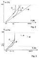
- Fig. 2
- Target deceleration curves with an increased deceleration gradient from reaching a predetermined threshold value of the brake pedal force, caused by the increase in the wheel brake pressure in a predetermined ratio to the admission pressure, without taking into account the resulting deceleration and
- Fig. 3
- a regulation of the deceleration from reaching a predetermined deceleration threshold value by means of the electronically controllable braking unit in accordance with an optimal deceleration target characteristic.
In Fig. 1 ist ein vom Fahrer zu betätigendes Bremspedal 1 mit einem Bremskraftverstärker
2 verbunden. Der Bremskraftverstärker 2 wirkt mit einem
Hauptbremszylinder 5 zusammen. Zwischen dem Hauptbremszylinder 5 und
den Radbremsen HL, HR, VL und VR ist eine elektronisch regelbare Bremseinheit
3 angeordnet. Die Aktuatoren der elektronisch regelbaren Bremseinheit
3 werden über ein elektronisches Steuergerät 6 angesteuert. Weiterhin
erfaßt das Steuergerät 6 den am Ausgang des Hauptbremszylinders 5 herrschenden
Vordruck (Pvor) mittels des Vordrucksensors 4. Darüber hinaus
weist das Steuergerät 6 weitere Ein- und Ausgänge für Ein- und Ausgangssignale
auf. Insbesondere erfaßt das Steuergerät 6 Signale, beispielsweise
die Bremsdruckwerte in den Radbremsen oder die Raddrehzahlen, durch die
zumindest indirekt die Fahrzeug-Ist-Verzögerung (-a) ermittelbar ist.In Fig. 1 is a
In den Fig. 2 und 3 ist die Verzögerung -a in % (0 - 100 %) über der Pedalbetätigungsgröße
F (N) (z. B. 0 - 300 N) aufgetragen. Die Pedalbetätigungsgröße
F entspricht hierbei vorzugsweise der durch den Fahrer über das
Bremspedal aufgebrachten Pedalkraft, die aus dem Vordruck gebildet wird,
der mittels des Vordrucksensors 4 am Ausgang des Hauptbremszylinders 5
gemessen wird. Im folgenden wird für die Pedalbetätigungsgröße F der Begriff
Im Ausführungsbeispiel nach Fig. 2 wird im elektronischen Steuergerät 6
(Fig. 1) allein der durch den Bremskraftverstärker 2 erreichte Pedalkraftverlauf
berücksichtigt. In Fig. 2 sind als Beispiele für die sich daraus ergebenden
Verzögerungen der Verzögerungsverlauf A für den günstigsten Fall und
der Verzögerungsverlauf B für den ungünstigsten Fall dargestellt. Der günstigste
Fall tritt insbesondere bei hohem Unterdruck, bei unbeladenem Fahrzeug,
bei hohem Belag-Reibwert und ohne Hängerbetrieb auf. Der ungünstigste
Fall liegt insbesondere bei niedrigem Unterdruck, bei voll beladenem
Fahrzeug, bei niedrigem Belag-Reibwert oder mit Hängerbetrieb vor. Die
Verzögerungsverläufe A und B mit durchgehend gleichbleibenden Verzögerungsgradienten
würden sich durch den Bremskraftverstärker nach dem
Stand der Technik ohne die erfindungsgemäße Bremsanlage einstellen. Erfindungsgemäß
wird jedoch im Steuergerät 6 die Pedalkraft F erfaßt. Mittels
des Steuergeräts 6 und der elektronisch regelbaren Bremseinheit wird ab
Erreichen des vorbestimmten Schwellwertes F2 der Pedalkraft F der
Bremsdruck in den Radbremsen HL, HR, VL und VR derart erzeugt, daß sich
bei einem weiteren Ansteigen der Pedalkraft F über den Schwellwert F2 hinaus
erhöhte Verzögerungsgradienten im Sinne einer Erhöhung des Bremskraftverstärker-Verhältnisses
entsprechend den Verzögerungsverläufen C
und D gegenüber den Verzögerungsverläufen A und B ergeben. Die
Ergänzend wird darauf hingewiesen, daß bekanntermaßen der Bremskraftverstärker erst ab Erreichen einer bestimmten Ansprech-Pedalkraft F1 wirksam wird. Zwischen der Ansprech-Pedalkraft F1 und dem Pedalkraft-Schwellwert F2 können sich auch Verzögerungsverläufe zwischen den Kurven A und B ergeben.In addition, it is pointed out that, as is known, the brake booster effective only when a certain response pedal force F1 is reached becomes. Between the response pedal force F1 and the pedal force threshold F2 can also show deceleration curves between the curves A and B result.
Abhängig von dem allein durch den Bremskraftverstärker 2 erreichten Verzögerungsverlauf (z. B. A oder B) können auch unterschiedliche Pedalkraft-Schwellwerte F2 definiert werden (in Fig. 2 nicht dargestellt). Depending on the deceleration curve achieved solely by the brake booster 2 (e.g. A or B) can also have different pedal force threshold values F2 can be defined (not shown in FIG. 2).
Entsprechend Fig. 2 steigen die erhöhten Verzögerungsgradienten nach den
Verzögerungsverläufen C und D mit dem weiteren Ansteigen der Pedalkraft
F über den Pedalkraft-Schwellwert F2 hinaus kontinuierlich weiter an. Hierdurch
wird ein
Fig. 3 zeigt eine Alternative zu dem in Fig. 2 dargestellten Ausführungsbeispiel. In Fig. 3 ist eine Verzögerungs-Sollkennlinie C dargestellt, die vorzugsweise für den günstigsten Fall empirisch ermittelt und im Steuergerät 6 abgespeichert ist. Auch kann die Verzögerungs-Sollkennlinie C, wie in Fig. 3 dargestellt, ab Erreichen eines vorbestimmten Pedalkraft-Schwellwertes F2 mit dem weiteren Ansteigen der Pedalkraft F einen kontinuierlich weiter ansteigenden erhöhten Verzögerungsgradienten aufweisen. Ein kontinuierlich weiter ansteigender erhöhter Verzögerungsgradient ist jedoch nicht zwingend erforderlich.Fig. 3 shows an alternative to the embodiment shown in Fig. 2. In Fig. 3, a target deceleration characteristic curve C is shown, which is preferably empirically determined for the best case and in the control unit 6 is saved. The desired deceleration characteristic curve C can also be, as in FIG. 3 shown, from reaching a predetermined pedal force threshold F2 with the further increase in the pedal force F a continuously increasing have increased deceleration gradients. A continuous however, a further increase in the deceleration gradient is not mandatory required.
Im elektronischen Steuergerät 6 wird zunächst bis zum Erreichen eines vorbestimmten Verzögerungs-Schwellwertes -a1, z. B. 30 %, der allein durch den Bremskraftverstärker 2 erreichte Ist-Verzögerungsverlauf, im Beispiel nach Fig. 3 entsprechend dem Verzögerungsverlauf B, erfaßt. Bei Erreichen des vorbestimmten Verzögerungs-Schwellwertes -a1 wird die zu diesem Zeitpunkt vorliegende Ist-Pedalkraft F3 festgestellt. Die Ist-Verzögerung für die Pedalkraft F3, die dem vorbestimmten Verzögerungs-Schwellwert -a1 entspricht, wird mit der Soll-Verzögerung, die entsprechend der Verzögerungs-Sollkennlinie C für diese Pedalkraft F3 vorgegeben ist, verglichen. Ist die Ist-Verzögerung kleiner als die Soll-Verzögerung für die Pedalkraft F3, wie in Fig. 3 dargestellt, wird mittels der elektronisch regelbaren Bremsenheit 3 der Bremsdruck in den Radbremsen im Sinne einer Regelung derart erzeugt, daß sich der Soll-Verzögerungsverlauf entsprechend der Verzögerungs-Sollkennlinie C ergibt; d. h. dem Soll-Verzögerungsverlauf C wird erst ab Erreichen eines vorbestimmten Verzögerungs-Schwellwertes -a1, hier z. B. 30 %, gefolgt. Alternativ kann dem Soll-Verzögerungsverlauf C auch erst ab Erreichen eines vorbestimmten Schwellwertes der Pedalkraft F, z. B. des Schwellwertes F2, gefolgt werden (hier nicht dargestellt). Erfindungsgemäß kann dem Soll-Verzögerungsverlauf C auch ständig gefolgt werden; d. h., ohne das Erreichen eines vorbestimmten Verzögerungs-Schwellwertes -a1 oder eines vorbestimmten Schwellwertes F2 der Pedalkraft F abzuwarten. Dies kann jedoch zu einer fast permanenten Regelung der Bremseinheit und damit zu einer Überforderung führen. Aus diesen Gründen ist es vorteilhafter, das Erreichen vorbestimmter Schwellwerte abzuwarten, bevor entsprechend der Verzögerungs-Sollkennlinie C geregelt wird.In the electronic control unit 6 is first until a predetermined is reached Delay threshold -a1, e.g. B. 30% by itself Actual deceleration curve reached the brake booster 2, in the example 3 according to the delay curve B, detected. When reached of the predetermined delay threshold value -a1 becomes the same Actual pedal force F3 determined at the time. The actual delay for the pedal force F3 which corresponds to the predetermined deceleration threshold value -a1 corresponds with the target deceleration corresponding to the target deceleration characteristic C is predetermined for this pedal force F3. Is the actual deceleration is smaller than the target deceleration for the pedal force F3, as shown in Fig. 3, by means of the electronically controllable braking unit 3, the brake pressure in the wheel brakes in the sense of a regulation generates that the target deceleration curve corresponding to the target deceleration characteristic C gives; d. H. the target deceleration curve C is only from reaching a predetermined delay threshold value -a1, here z. B. 30% followed. Alternatively, the target deceleration curve C can also first from reaching a predetermined threshold value of the pedal force F, e.g. B. of Threshold F2, are followed (not shown here). According to the invention the target deceleration curve C can also be continuously followed; d. H., without reaching a predetermined deceleration threshold value -a1 or to wait for a predetermined threshold value F2 of the pedal force F. However, this can lead to an almost permanent regulation of the braking unit and thus lead to an overload. For these reasons, it is more advantageous wait until predetermined thresholds are reached before doing so the target deceleration characteristic curve C is regulated.
Darüber hinaus wird vorzugsweise, wie in Fig. 3 dargestellt, der Ist-Verzögerungsverlauf entsprechend einer stetig differenzierbaren Kurve D, z. B. mit Hilfe der Definition eines Verstärkungsfaktors, an den Soll-Verzögerungsverlauf C angepaßt, um durch einen weichen Übergang den Komfort der Bremsanlage zu erhöhen.In addition, the actual deceleration curve is preferably, as shown in FIG. 3 according to a continuously differentiable curve D, z. B. with the help of the definition of a gain factor, to the target deceleration curve C adapted to the through a soft transition To increase the comfort of the braking system.
Somit sind durch die erfindungsgemäße Bremsanlage alle Vorteile erreicht, die man durch einen Bremskraftverstärker mit beliebig einstellbaren Verstärkungsverhältnis erreichen würde, ohne bereits bekannte Bremsanlagen mechanisch verändern zu müssen.Thus, all advantages are achieved by the brake system according to the invention, which you get through a brake booster with any adjustable gain ratio would achieve mechanically without already known braking systems to have to change.
Claims (7)
Applications Claiming Priority (2)
| Application Number | Priority Date | Filing Date | Title |
|---|---|---|---|
| DE19743960 | 1997-10-04 | ||
| DE19743960A DE19743960A1 (en) | 1997-10-04 | 1997-10-04 | Brake system for motor vehicles |
Publications (2)
| Publication Number | Publication Date |
|---|---|
| EP0906859A1 true EP0906859A1 (en) | 1999-04-07 |
| EP0906859B1 EP0906859B1 (en) | 2003-11-26 |
Family
ID=7844644
Family Applications (1)
| Application Number | Title | Priority Date | Filing Date |
|---|---|---|---|
| EP98116489A Expired - Lifetime EP0906859B1 (en) | 1997-10-04 | 1998-09-01 | Braking system for vehicles |
Country Status (5)
| Country | Link |
|---|---|
| US (1) | US6212459B1 (en) |
| EP (1) | EP0906859B1 (en) |
| JP (1) | JP4227688B2 (en) |
| DE (2) | DE19743960A1 (en) |
| ES (1) | ES2212183T3 (en) |
Cited By (3)
| Publication number | Priority date | Publication date | Assignee | Title |
|---|---|---|---|---|
| EP1108633A1 (en) * | 1999-12-13 | 2001-06-20 | Toyota Jidosha Kabushiki Kaisha | Braking system wherein brake operating force is made larger than a value corresponding to booster output |
| EP1120323A3 (en) * | 2000-01-26 | 2003-08-06 | Bayerische Motoren Werke Aktiengesellschaft | Braking system for motor vehicles |
| WO2010015329A1 (en) * | 2008-08-06 | 2010-02-11 | Lucas Automotive Gmbh | Method and device for hydraulic brake boosting |
Families Citing this family (23)
| Publication number | Priority date | Publication date | Assignee | Title |
|---|---|---|---|---|
| DE19817326A1 (en) * | 1998-04-18 | 1999-10-21 | Continental Teves Ag & Co Ohg | Method of reducing braking distance to enable suitable deceleration in all driving situations |
| US6738601B1 (en) * | 1999-10-21 | 2004-05-18 | Broadcom Corporation | Adaptive radio transceiver with floating MOSFET capacitors |
| JP3700523B2 (en) * | 2000-02-25 | 2005-09-28 | 株式会社日立製作所 | Booster control device |
| DE10062978A1 (en) * | 2000-12-16 | 2002-06-20 | Bayerische Motoren Werke Ag | Method and device for controlling the brake system of a vehicle |
| JP4590137B2 (en) * | 2001-08-29 | 2010-12-01 | 本田技研工業株式会社 | Curved road running support device |
| WO2003068575A1 (en) * | 2002-02-14 | 2003-08-21 | Continental Teves Ag & Co. Ohg | Method and device for monitoring and/or modifying brake pressures |
| DE10335589A1 (en) * | 2003-07-31 | 2005-03-03 | Continental Teves Ag & Co. Ohg | Method for operating a vehicle brake system |
| JP4483225B2 (en) * | 2003-08-21 | 2010-06-16 | 株式会社アドヴィックス | Electric brake device |
| DE102004022993B4 (en) * | 2004-05-10 | 2007-04-05 | Lucas Automotive Gmbh | Brake system for a vehicle and method for driving such a brake system |
| US20060043790A1 (en) * | 2004-08-27 | 2006-03-02 | Spieker Arnold H | Method for detecting brake circuit failure |
| DE102006028118B4 (en) * | 2006-06-15 | 2016-10-13 | Volkswagen Ag | Brake system in a motor vehicle and a suitable sensor |
| US8255103B2 (en) * | 2007-03-27 | 2012-08-28 | GM Global Technology Operations LLC | Electronic brake system pedal release transition control apparatus and method |
| US8392088B2 (en) * | 2007-10-16 | 2013-03-05 | GM Global Technology Operations LLC | Brake assist driver command for vehicles |
| US8364367B2 (en) * | 2007-10-16 | 2013-01-29 | GM Global Technology Operations LLC | Brake assist exit method and system for vehicles |
| US8050836B2 (en) * | 2007-10-17 | 2011-11-01 | GM Global Technology Operations LLC | Method and system for determining initiation of a panic braking maneuver |
| JP4497230B2 (en) | 2008-05-12 | 2010-07-07 | トヨタ自動車株式会社 | BRAKE CONTROL DEVICE AND BRAKE CONTROL METHOD |
| JP5217834B2 (en) * | 2008-09-22 | 2013-06-19 | トヨタ自動車株式会社 | Traction drive vehicle with different braking assistance when towing and when not towing |
| DE102010042589A1 (en) * | 2010-10-18 | 2012-04-19 | Robert Bosch Gmbh | Method for automatically braking a vehicle |
| JP5761373B2 (en) * | 2011-12-14 | 2015-08-12 | トヨタ自動車株式会社 | Brake device and braking control device |
| DE102012223296A1 (en) * | 2012-12-14 | 2014-06-18 | Continental Teves Ag & Co. Ohg | Method for operating a brake system |
| DE102013209006A1 (en) * | 2013-05-15 | 2014-11-20 | Robert Bosch Gmbh | Control device for a brake-boosted autonomous braking system of a vehicle and method for operating a brake-boosted autonomous braking system of a vehicle |
| KR102115716B1 (en) * | 2013-10-07 | 2020-05-27 | 현대모비스 주식회사 | Electronic hydraulic brake device |
| DE102015224601A1 (en) * | 2015-12-08 | 2017-06-08 | Robert Bosch Gmbh | Method and control unit for controlling a hydraulic brake system |
Citations (4)
| Publication number | Priority date | Publication date | Assignee | Title |
|---|---|---|---|---|
| DE9110739U1 (en) * | 1990-09-06 | 1991-10-24 | Daimler-Benz Aktiengesellschaft, 7000 Stuttgart, De | |
| WO1993024353A1 (en) * | 1992-05-26 | 1993-12-09 | Lucas Industries Public Limited Company | Process for regulating the braking pressure using a brake servo |
| DE4440290C1 (en) * | 1994-11-11 | 1995-12-07 | Daimler Benz Ag | Release threshold determination system for vehicle automatic braking |
| DE19615805A1 (en) * | 1996-04-20 | 1997-10-23 | Bosch Gmbh Robert | Vehicle braking unit control and control circuit |
Family Cites Families (10)
| Publication number | Priority date | Publication date | Assignee | Title |
|---|---|---|---|---|
| JPS4918675B1 (en) * | 1969-08-10 | 1974-05-11 | ||
| DE4309850C2 (en) * | 1993-03-26 | 1996-12-12 | Lucas Ind Plc | Brake booster system for regulating a brake pressure with a brake booster |
| DE4329140C1 (en) * | 1993-08-30 | 1994-12-01 | Daimler Benz Ag | Brake pressure control device |
| KR0168492B1 (en) * | 1994-06-06 | 1998-12-15 | 나까무라 히로까즈 | Braking device for a vehicle |
| DE19524939C2 (en) * | 1995-07-08 | 1997-08-28 | Bosch Gmbh Robert | Method and device for controlling the brake system of a vehicle |
| DE19525985A1 (en) * | 1995-07-17 | 1997-01-23 | Bayerische Motoren Werke Ag | Brake system for motor vehicles with a brake booster |
| DE19542654A1 (en) * | 1995-11-15 | 1997-05-22 | Lucas Ind Plc | Electronic controllable braking system for motor vehicles |
| ES2130749T3 (en) * | 1996-04-03 | 1999-07-01 | Lucas Ind Plc | ELECTRONICALLY REGULATED POWER BRAKE. |
| DE69716225T2 (en) * | 1996-12-27 | 2003-07-10 | Denso Corp | Automotive brake system |
| DE19743959A1 (en) * | 1997-10-04 | 1999-04-08 | Bayerische Motoren Werke Ag | Brake system for motor vehicles |
-
1997
- 1997-10-04 DE DE19743960A patent/DE19743960A1/en not_active Withdrawn
-
1998
- 1998-09-01 EP EP98116489A patent/EP0906859B1/en not_active Expired - Lifetime
- 1998-09-01 ES ES98116489T patent/ES2212183T3/en not_active Expired - Lifetime
- 1998-09-01 DE DE59810250T patent/DE59810250D1/en not_active Expired - Lifetime
- 1998-10-01 JP JP28002298A patent/JP4227688B2/en not_active Expired - Fee Related
- 1998-10-05 US US09/166,150 patent/US6212459B1/en not_active Expired - Lifetime
Patent Citations (4)
| Publication number | Priority date | Publication date | Assignee | Title |
|---|---|---|---|---|
| DE9110739U1 (en) * | 1990-09-06 | 1991-10-24 | Daimler-Benz Aktiengesellschaft, 7000 Stuttgart, De | |
| WO1993024353A1 (en) * | 1992-05-26 | 1993-12-09 | Lucas Industries Public Limited Company | Process for regulating the braking pressure using a brake servo |
| DE4440290C1 (en) * | 1994-11-11 | 1995-12-07 | Daimler Benz Ag | Release threshold determination system for vehicle automatic braking |
| DE19615805A1 (en) * | 1996-04-20 | 1997-10-23 | Bosch Gmbh Robert | Vehicle braking unit control and control circuit |
Cited By (6)
| Publication number | Priority date | Publication date | Assignee | Title |
|---|---|---|---|---|
| EP1108633A1 (en) * | 1999-12-13 | 2001-06-20 | Toyota Jidosha Kabushiki Kaisha | Braking system wherein brake operating force is made larger than a value corresponding to booster output |
| US6460944B2 (en) | 1999-12-13 | 2002-10-08 | Toyota Jidosha Kabushiki Kaisha | Braking system wherein brake operating force is made larger than a value corresponding to booster output |
| EP1120323A3 (en) * | 2000-01-26 | 2003-08-06 | Bayerische Motoren Werke Aktiengesellschaft | Braking system for motor vehicles |
| WO2010015329A1 (en) * | 2008-08-06 | 2010-02-11 | Lucas Automotive Gmbh | Method and device for hydraulic brake boosting |
| CN102143870A (en) * | 2008-08-06 | 2011-08-03 | 卢卡斯汽车股份有限公司 | Method and device for hydraulic brake boosting |
| CN102143870B (en) * | 2008-08-06 | 2015-04-22 | 卢卡斯汽车股份有限公司 | Method and device for hydraulic brake boosting |
Also Published As
| Publication number | Publication date |
|---|---|
| US6212459B1 (en) | 2001-04-03 |
| JPH11157429A (en) | 1999-06-15 |
| DE59810250D1 (en) | 2004-01-08 |
| ES2212183T3 (en) | 2004-07-16 |
| DE19743960A1 (en) | 1999-04-08 |
| EP0906859B1 (en) | 2003-11-26 |
| JP4227688B2 (en) | 2009-02-18 |
Similar Documents
| Publication | Publication Date | Title |
|---|---|---|
| EP0906859B1 (en) | Braking system for vehicles | |
| EP0616932B1 (en) | Servo brake booster system for control of a brake pressure with a brake booster | |
| EP0776286B1 (en) | Process for controlling braking pressure depending on the rate of pedal operation | |
| EP0824433B1 (en) | Setpoint generator | |
| EP2018302B1 (en) | Method for regulating the brake pressure in motorcycles | |
| EP1424254A2 (en) | Method for applying an automatic braking | |
| DE19750977B4 (en) | braking system | |
| DE102013216157A1 (en) | Method for controlling a brake system for motor vehicles | |
| DE102009046629A1 (en) | Control device for a braking device | |
| EP0906858A1 (en) | Brake system for vehicles | |
| DE102013224967A1 (en) | Method for controlling an electromechanical actuator and regulating device | |
| DE4406128C1 (en) | Method for performing an automatic braking sequence for a motor vehicle brake unit with an antilock system | |
| DE10316351A1 (en) | Integrated brake for a motorbike with front and rear brake control has pressure intensifying unit in rear brake lead to increase the rear brake pressure | |
| DE102013217579A1 (en) | Method for operating an electromechanical brake booster of a brake system, method for operating a recuperative brake system and control device for at least one electromechanical brake booster of a brake system | |
| DE19615805A1 (en) | Vehicle braking unit control and control circuit | |
| DE10124591B4 (en) | Method for operating a brake assist system | |
| DE10118635B4 (en) | Method for operating a brake assist system | |
| DE102012200494A1 (en) | Method for controlling brake assembly of motor vehicle, involves determining manipulated variable to actuate electromechanical actuator based on pressure reference value and modulus value of pressure actual value of pressurizing device | |
| DE102018213935A1 (en) | HBA threshold pressure adjustment method and apparatus for performing the method | |
| DE102012222718A1 (en) | Control device for a brake system of a vehicle and method for operating a brake system of a vehicle | |
| DE102012223898A1 (en) | Method for operating a hydraulic brake system of a motor vehicle and hydraulic brake system | |
| WO2019011538A1 (en) | Method for operating a braking assembly of a motor vehicle, and control and/or regulation device | |
| DE19822859A1 (en) | Commercial vehicle braking system for co-ordinated braking | |
| DE19981604B4 (en) | Method for operating a brake assist system | |
| DE19545010B4 (en) | Arrangement for controlling the speed of a motor vehicle in the event of unwanted acceleration |
Legal Events
| Date | Code | Title | Description |
|---|---|---|---|
| PUAI | Public reference made under article 153(3) epc to a published international application that has entered the european phase |
Free format text: ORIGINAL CODE: 0009012 |
|
| AK | Designated contracting states |
Kind code of ref document: A1 Designated state(s): DE ES FR GB IT SE |
|
| AX | Request for extension of the european patent |
Free format text: AL;LT;LV;MK;RO;SI |
|
| 17P | Request for examination filed |
Effective date: 19990901 |
|
| AKX | Designation fees paid |
Free format text: DE ES FR GB IT SE |
|
| 17Q | First examination report despatched |
Effective date: 20020403 |
|
| GRAH | Despatch of communication of intention to grant a patent |
Free format text: ORIGINAL CODE: EPIDOS IGRA |
|
| GRAS | Grant fee paid |
Free format text: ORIGINAL CODE: EPIDOSNIGR3 |
|
| GRAA | (expected) grant |
Free format text: ORIGINAL CODE: 0009210 |
|
| AK | Designated contracting states |
Kind code of ref document: B1 Designated state(s): DE ES FR GB IT SE |
|
| REG | Reference to a national code |
Ref country code: GB Ref legal event code: FG4D Free format text: NOT ENGLISH |
|
| GBT | Gb: translation of ep patent filed (gb section 77(6)(a)/1977) |
Effective date: 20031128 |
|
| REF | Corresponds to: |
Ref document number: 59810250 Country of ref document: DE Date of ref document: 20040108 Kind code of ref document: P |
|
| REG | Reference to a national code |
Ref country code: SE Ref legal event code: TRGR |
|
| ET | Fr: translation filed | ||
| REG | Reference to a national code |
Ref country code: ES Ref legal event code: FG2A Ref document number: 2212183 Country of ref document: ES Kind code of ref document: T3 |
|
| PLBE | No opposition filed within time limit |
Free format text: ORIGINAL CODE: 0009261 |
|
| STAA | Information on the status of an ep patent application or granted ep patent |
Free format text: STATUS: NO OPPOSITION FILED WITHIN TIME LIMIT |
|
| 26N | No opposition filed |
Effective date: 20040827 |
|
| REG | Reference to a national code |
Ref country code: FR Ref legal event code: PLFP Year of fee payment: 18 |
|
| PGFP | Annual fee paid to national office [announced via postgrant information from national office to epo] |
Ref country code: ES Payment date: 20150820 Year of fee payment: 18 Ref country code: GB Payment date: 20150924 Year of fee payment: 18 |
|
| PGFP | Annual fee paid to national office [announced via postgrant information from national office to epo] |
Ref country code: SE Payment date: 20150911 Year of fee payment: 18 Ref country code: FR Payment date: 20150928 Year of fee payment: 18 |
|
| PGFP | Annual fee paid to national office [announced via postgrant information from national office to epo] |
Ref country code: IT Payment date: 20150924 Year of fee payment: 18 |
|
| PGFP | Annual fee paid to national office [announced via postgrant information from national office to epo] |
Ref country code: DE Payment date: 20150919 Year of fee payment: 18 |
|
| REG | Reference to a national code |
Ref country code: DE Ref legal event code: R119 Ref document number: 59810250 Country of ref document: DE |
|
| PG25 | Lapsed in a contracting state [announced via postgrant information from national office to epo] |
Ref country code: SE Free format text: LAPSE BECAUSE OF NON-PAYMENT OF DUE FEES Effective date: 20160902 |
|
| REG | Reference to a national code |
Ref country code: SE Ref legal event code: EUG |
|
| GBPC | Gb: european patent ceased through non-payment of renewal fee |
Effective date: 20160901 |
|
| REG | Reference to a national code |
Ref country code: FR Ref legal event code: ST Effective date: 20170531 |
|
| PG25 | Lapsed in a contracting state [announced via postgrant information from national office to epo] |
Ref country code: FR Free format text: LAPSE BECAUSE OF NON-PAYMENT OF DUE FEES Effective date: 20160930 Ref country code: GB Free format text: LAPSE BECAUSE OF NON-PAYMENT OF DUE FEES Effective date: 20160901 Ref country code: DE Free format text: LAPSE BECAUSE OF NON-PAYMENT OF DUE FEES Effective date: 20170401 |
|
| PG25 | Lapsed in a contracting state [announced via postgrant information from national office to epo] |
Ref country code: IT Free format text: LAPSE BECAUSE OF NON-PAYMENT OF DUE FEES Effective date: 20160901 |
|
| PG25 | Lapsed in a contracting state [announced via postgrant information from national office to epo] |
Ref country code: ES Free format text: LAPSE BECAUSE OF NON-PAYMENT OF DUE FEES Effective date: 20160902 |
|
| REG | Reference to a national code |
Ref country code: ES Ref legal event code: FD2A Effective date: 20180625 |