EP0908668A2 - Fire resistant lighting enclosure - Google Patents
Fire resistant lighting enclosure Download PDFInfo
- Publication number
- EP0908668A2 EP0908668A2 EP98307487A EP98307487A EP0908668A2 EP 0908668 A2 EP0908668 A2 EP 0908668A2 EP 98307487 A EP98307487 A EP 98307487A EP 98307487 A EP98307487 A EP 98307487A EP 0908668 A2 EP0908668 A2 EP 0908668A2
- Authority
- EP
- European Patent Office
- Prior art keywords
- housing
- enclosure
- mounting
- spaced apart
- fire resistant
- Prior art date
- Legal status (The legal status is an assumption and is not a legal conclusion. Google has not performed a legal analysis and makes no representation as to the accuracy of the status listed.)
- Withdrawn
Links
Images


Classifications
-
- F—MECHANICAL ENGINEERING; LIGHTING; HEATING; WEAPONS; BLASTING
- F21—LIGHTING
- F21S—NON-PORTABLE LIGHTING DEVICES; SYSTEMS THEREOF; VEHICLE LIGHTING DEVICES SPECIALLY ADAPTED FOR VEHICLE EXTERIORS
- F21S8/00—Lighting devices intended for fixed installation
- F21S8/02—Lighting devices intended for fixed installation of recess-mounted type, e.g. downlighters
- F21S8/026—Lighting devices intended for fixed installation of recess-mounted type, e.g. downlighters intended to be recessed in a ceiling or like overhead structure, e.g. suspended ceiling
-
- F—MECHANICAL ENGINEERING; LIGHTING; HEATING; WEAPONS; BLASTING
- F21—LIGHTING
- F21S—NON-PORTABLE LIGHTING DEVICES; SYSTEMS THEREOF; VEHICLE LIGHTING DEVICES SPECIALLY ADAPTED FOR VEHICLE EXTERIORS
- F21S8/00—Lighting devices intended for fixed installation
- F21S8/02—Lighting devices intended for fixed installation of recess-mounted type, e.g. downlighters
-
- F—MECHANICAL ENGINEERING; LIGHTING; HEATING; WEAPONS; BLASTING
- F21—LIGHTING
- F21V—FUNCTIONAL FEATURES OR DETAILS OF LIGHTING DEVICES OR SYSTEMS THEREOF; STRUCTURAL COMBINATIONS OF LIGHTING DEVICES WITH OTHER ARTICLES, NOT OTHERWISE PROVIDED FOR
- F21V25/00—Safety devices structurally associated with lighting devices
Definitions
- This invention relates to an enclosure for preventing the spread of fires in buildings, and more particularly, to fire resistant enclosures for recessed fixtures, such as, for example, lighting fixtures, as well as methods of fabricating and installing the same.
- recessed fixtures such as, for example, lighting fixtures and loudspeaker units
- a typical twenty dwelling unit building can therefore have hundreds of recessed lighting fixtures.
- the present invention is directed to a preformed fire resistant enclosure for recessed fixtures employed in residential and commercial buildings which conforms with applicable building codes relating to firestop systems for ceiling/floor penetrations.
- the fire resistant enclosure of the invention is described and illustrated in relation to a recessed lighting fixture. However, those skilled in the art will readily appreciate that it is suitable for use in conjunction with other recessed fixtures, such as, for example, loudspeaker units.
- the preferred enclosure includes a housing formed from common sheet metal, such as, for example, 26 gauge sheet metal, or a similar inexpensive readily available material.
- the preferred housing is defined by a top wall and first through fourth side walls.
- the top wall and side walls have exterior and interior wall surfaces, and at least the interior wall surfaces of the enclosure have a fire resistant material provided thereon. It is envisaged that the fire resistant material may also be provided on the exterior surfaces of the enclosure to further enhance its fire suppression characteristics.
- planar flanges preferably extend outwardly from edges of the side walls of the housing to facilitate mounting of the housing between spaced apart building joists.
- the first and third side walls of the housing are opposite one another and are dimensioned to facilitate mounting of the housing between joists spaced at 12.0 inch centres
- the second and fourth walls of the housing are opposite one another and are dimensioned to facilitate mounting of the housing between joists spaced at 16.0 inch centres.
- Each of the side walls of the enclosure are preferably provided with an aperture to accommodate the passage of electrical wires associated with a lighting fixture.
- the apertures may be defined by perforated knock-outs which can be selectively opened to accommodate wiring.
- the fire resistant material associated with the interior surfaces of the lighting enclosure is selected from a group of fire resistant materials consisting of cementitious and intumescent materials. Such materials are commercially available in a wide variety of forms including coatings, films or sheetings, and can be applied by spraying, rolling, brushing or other similar methods known in the art.
- the invention is also directed to a method of installing recessed fixtures.
- This method includes the steps of providing a housing configured to enclose a recessed fixture, providing at least interior surfaces of the housing with a fire resistant material, and mounting the housing between spaced apart building joists.
- the step of providing surfaces of the housing with a resistant enclosure precedes the step of mounting the housing between spaced apart building joists.
- at least interior surfaces of the enclosure may be provided with the fire resistant material after the enclosure has been mounted between spaced apart joists.
- the method further includes the steps of placing a fixture within the housing, passing electrical wires through an aperture formed in at least one side wall of the housing, and sealing the aperture after passing the electrical wires therethrough.
- the method also includes the step of positioning the enclosure in a first orientation for mounting between building joists spaced at 12.0 inch centres, or positioning the enclosure in a second orientation for mounting between building joists spaced at 12.0 inch centres.
- FIG. 1 a fire rated lighting enclosure designated generally by reference numeral 10.
- Lighting enclosure 10 has a generally rectangular box-like configuration which encloses a conventional recessed lighting fixture 12 when installed between adjacent ceiling joists, as shown for example in Figures 5 and 6. Once installed, the fire rated lighting enclosure 10 provides a lightweight, durable, readily adaptable structure which advantageously isolates a heat generating recessed lighting fixture 12 from combustible insulation material adjacent thereto, and prohibits the propagation of fire through the ceiling penetration associated with the lighting fixture in conformance with applicable building codes.
- lighting enclosure 10 is constructed from a blank which is stamped from conventional 26 gauge sheet metal, expanded metal, metal mesh, or similar inexpensive material.
- Enclosure 10 includes a top wall 20 and first through fourth side walls 22, 24, 26 and 28.
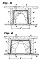
- the first and third side walls 22 and 26 are opposite one another and have a greater lengthwise dimension than the opposed second and third side walls 24 and 28. More particularly, the lengthwise dimension of the first and third side walls 22 and 26 is selected to facilitate mounting of the lighting enclosure 10 between ceiling joists spaced 16.0 inch centres, as illustrated in Figure 6, while the lengthwise dimension of the second and fourth side walls 24 and 28 is selected to facilitate mounting of the lighting enclosure 10 between ceiling joists spaced at 12.0 inch centres, as illustrated in Figure 5.
- the second and fourth side walls 24 and 28 are each provided with opposed lateral tabs 24a and 24b, and 28a and 28b, respectively. These lateral tabs are configured for attachment to the first and third side walls 22 and 26 to facilitate construction of the enclosure 10, as shown for example in Figure 3. Those skilled in the art will readily appreciate that the lateral tabs could alternatively be provided on the first and third side walls 24 and 28.
- the tabs are preferably secured to the first and third side walls of the enclosure by spot welding or a similar metal joining technique well known in the art. Other methods of joining the side walls are also envisioned, such as, for example, welding or securement with fasteners and brackets.
- Mounting means are provided on each of the four side walls of enclosure 10 and include flanges 32, 34, 36 and 38 which depend outwardly from the bottom edges of the first through fourth side walls 22, 24, 26 and 28, respectively.
- the first through fourth side walls of lighting enclosure 10 are each provided with an aperture for accommodating electrical wires of a recessed lighting fixture enclosed thereby.
- These include apertures 42, 44, 46 and 48 which are preferably stamped through the side walls, but which in the alternative, may be provided as perforated knock-outs, a concept that is common in the construction industry.
- the interior surfaces of lighting enclosure 10 are provided with a layer or covering material, designated generally by reference numeral 50, which is intended to prevent the propagation of fire.
- the material 50 is selected from a group of fire resistant materials including cementitious and intumescent materials, or other tested and approved materials.
- Cementitious fire proofing materials are inorganic materials that are supplied as a powder which is mixed with water and sprayed on surfaces, such as the interior of enclosure 10, in a thickness and density required to achieve fire resistant ratings in accordance with known building codes. Typically, the hourly fire rating for such materials will vary from one to four hours depending upon the applied thickness or number of material layers. In a preferred embodiment of the invention, such a material is applied with a thickness of about 0.0625 inches to about 1.50 inches.
- a suitable cementitious fire proofing material is marketed under the tradename PYROLITE 15/RETRO-LITE 15 which is manufactured and sold by Carboline Fireproofing Products Division, of St. Louis, Missouri.
- Intumescent fireproofing materials form a passive fire protection which remains inactive until subjected to levels of heat when the material expands.
- Thin film intumescent coatings having a thickness of about 0.0125 inches which may be brushed, rolled or sprayed on steel surfaces are marketed under the tradename Cafco and are available from Isolatek International of Stanhope, New Jersey.
- Itumescent composite sheeting materials are also available from 3M Corporation of St. Paul, Minnesota. These sheets may be cut to desired dimensions and provided with blank openings or penetrations to conform to the geometry of lighting enclosure 10.
- the fire resistant material is applied to the interior wall surfaces of lighting enclosure 10 during fabrication, i.e. prior to installation between two spaced apart ceiling joists.
- the fire resistant material may be applied to the interior wall surfaces of the lighting enclosure after it has been installed between two spaced apart ceiling joists.
- fire resistant coating materials may be applied to the exterior wall surfaces of the lighting enclosure 10, as shown for example in Figures 5 and 6.
- mounting flanges 32 and 36 are employed.
- Conventional screw-type fasteners 60 are utilized to secure the mounting flanges to the lower chords of two spaced apart ceiling joists 62 and 64.
- fasteners may be employed to secure the mounting flanges to the ceiling joists.
- a recessed lighting fixture 20 is placed therein and secured in a conventional manner utilizing threaded fasteners or the like. Thereafter, a selected one of the apertures 44 formed in the walls of the enclosure is knocked-out to accommodate electrical wiring 16 associated with lighting fixture 12.
- a suitable fire-proofing material such as an intumescent or cementitious material, can then be applied in the area of the wire penetrated aperture to seal the interior of the enclosure, and thereby isolate the lighting fixture 12 from the insulating material 66 disposed between joists 62 and 64.
- a piece of material 66 is attached to joists 62 and 64 in a conventional manner to define the ceiling of the building construction and a penetration 68 for the recessed lighting fixture mounted thereabove.
- lighting enclosure 10 when lighting enclosure 10 is installed between two ceiling joists 72 and 74 spaced at 16.0 inch centres, it is disposed in a second orientation in which the opposed mounting flanges 34 and 38 are employed to secure the enclosure to the lower chords of two spaced apart ceiling joists.
Abstract
Description
- This invention relates to an enclosure for preventing the spread of fires in buildings, and more particularly, to fire resistant enclosures for recessed fixtures, such as, for example, lighting fixtures, as well as methods of fabricating and installing the same.
- In residential and commercial buildings, it is commonplace to provide insulation materials between ceiling joists to reduce heat loss from the living spaces. It is also commonplace to install recessed fixtures, such as, for example, lighting fixtures and loudspeaker units, in the living spaces which include portions that extend through the ceiling between the ceiling joists. A typical twenty dwelling unit building can therefore have hundreds of recessed lighting fixtures.
- It is well known that during use, recessed fixtures, and in particular recessed lighting fixtures tend to generate a significant amount of heat, and because some insulating materials utilised in residential buildings are combustible, a fire hazard generally exists. Building Regulations generally require that openings or penetrations for recessed lighting fixtures in all wood framed ceiling assemblies must be protected by a penetration firestop system. Such a system must limit the spread of fire, flame or hot gases through the firestop assembly for an acceptable period of time, when tested in accordance with a predetermined time-temperature curve set by the Regulations.
- There have been attempts in the prior art to provide fire rated enclosures which isolate recessed fixtures, such as lighting and speaker units, from combustible insulation materials so as to reduce the risk of fire, and which conform with applicable building codes to prevent the spread of fire. For example, it is known in the construction industry to build a sheet rock enclosure around a recessed lighting fixture to isolate the fixture from insulation materials, and to provide a suitable firestop system for the ceiling penetration. To accomplish this, the joist space in which the lighting fixture is to be installed must first be blocked by a carpenter so that the joists can carry the sheet rock enclosure. The sheet rock is then attached to the joists and sealed. This prior art method is extremely labour intensive and very costly.
- An example of an insulation barrier constructed from a plurality of panels fabricated from a fire-proof material such as Portland cement reinforced with asbestos fibers, and joined together by clips is disclosed in US patent No. 4237671. The prefabricated panels are dimensioned to accommodate different joist spacings, but they must be constructed at the building site for utilization. Examples of preformed insulation barriers constructed from aluminium sheet metal are disclosed in US patents Nos. 4375142 and 4400766. Both of these devices include perforations to facilitate construction, and therefore they do not provide a firestop system which conforms with applicable building codes. Furthermore, aluminium sheet metal is a relatively expensive material, and its usage adds significantly to the cost of construction. clearly, there is a need in the art for an inexpensive preformed insulation barrier which conforms with the firestop requirements of applicable building codes.
- The present invention is directed to a preformed fire resistant enclosure for recessed fixtures employed in residential and commercial buildings which conforms with applicable building codes relating to firestop systems for ceiling/floor penetrations. In the specification which follows, the fire resistant enclosure of the invention is described and illustrated in relation to a recessed lighting fixture. However, those skilled in the art will readily appreciate that it is suitable for use in conjunction with other recessed fixtures, such as, for example, loudspeaker units.
- The preferred enclosure includes a housing formed from common sheet metal, such as, for example, 26 gauge sheet metal, or a similar inexpensive readily available material. The preferred housing is defined by a top wall and first through fourth side walls. The top wall and side walls have exterior and interior wall surfaces, and at least the interior wall surfaces of the enclosure have a fire resistant material provided thereon. It is envisaged that the fire resistant material may also be provided on the exterior surfaces of the enclosure to further enhance its fire suppression characteristics.
- Generally planar flanges preferably extend outwardly from edges of the side walls of the housing to facilitate mounting of the housing between spaced apart building joists. Preferably, the first and third side walls of the housing are opposite one another and are dimensioned to facilitate mounting of the housing between joists spaced at 12.0 inch centres, and the second and fourth walls of the housing are opposite one another and are dimensioned to facilitate mounting of the housing between joists spaced at 16.0 inch centres. Thus, the fire resistant enclosure of the subject invention is readily adaptable to different joist spacings. Those skilled in the art will readily appreciate that the dimensions of the housing can be modified to accommodate other joist spacings.
- Each of the side walls of the enclosure are preferably provided with an aperture to accommodate the passage of electrical wires associated with a lighting fixture. The apertures may be defined by perforated knock-outs which can be selectively opened to accommodate wiring. Preferably, the fire resistant material associated with the interior surfaces of the lighting enclosure is selected from a group of fire resistant materials consisting of cementitious and intumescent materials. Such materials are commercially available in a wide variety of forms including coatings, films or sheetings, and can be applied by spraying, rolling, brushing or other similar methods known in the art.
- The invention is also directed to a method of installing recessed fixtures. This method includes the steps of providing a housing configured to enclose a recessed fixture, providing at least interior surfaces of the housing with a fire resistant material, and mounting the housing between spaced apart building joists. Preferably, the step of providing surfaces of the housing with a resistant enclosure precedes the step of mounting the housing between spaced apart building joists. Although, it is envisaged that at least interior surfaces of the enclosure may be provided with the fire resistant material after the enclosure has been mounted between spaced apart joists.
- The method further includes the steps of placing a fixture within the housing, passing electrical wires through an aperture formed in at least one side wall of the housing, and sealing the aperture after passing the electrical wires therethrough. The method also includes the step of positioning the enclosure in a first orientation for mounting between building joists spaced at 12.0 inch centres, or positioning the enclosure in a second orientation for mounting between building joists spaced at 12.0 inch centres.
- These and other features of the invention will become more readily understood from the following detailed description thereof, by way of example only, with reference to the accompanying drawings, in which:
- Figure 1 is a perspective view of a lighting enclosure of the invention, sectioned to illustrate the fire resistant material provided on the interior surfaces thereof, and further illustrating the recessed lighting fixture which the enclosure is configured to house;
- Figure 2 is a top plan view of the stamped sheet metal blank from which the lighting enclosure illustrated in Figure 1 is constructed;
- Figure 3 illustrates the manner in which the stamped sheet metal blank illustrated in Figure 2 is folded to form the enclosure of Figure 1;
- Figure 4 is a perspective view of a lighting enclosure of the invention as oriented during installation between two adjacent ceiling joists;
- Figure 5 is a side elevational view in cross section of the lighting enclosure of the invention mounted in a first orientation between ceiling joists spaced at 12.0 inch centres; and
- Figure 6 is a side elevational view in cross section of the lighting enclosure of the invention mounted in a second orientation between ceiling joists spaced at 16.0 inch centres.
-
- Referring now in detail to the drawings wherein like reference numerals identify the same or similar parts, there is illustrated in Figure 1 a fire rated lighting enclosure designated generally by
reference numeral 10.Lighting enclosure 10 has a generally rectangular box-like configuration which encloses a conventionalrecessed lighting fixture 12 when installed between adjacent ceiling joists, as shown for example in Figures 5 and 6. Once installed, the fire ratedlighting enclosure 10 provides a lightweight, durable, readily adaptable structure which advantageously isolates a heat generating recessedlighting fixture 12 from combustible insulation material adjacent thereto, and prohibits the propagation of fire through the ceiling penetration associated with the lighting fixture in conformance with applicable building codes. - Referring to Figure 1 in conjunction with Figure 2,
lighting enclosure 10 is constructed from a blank which is stamped from conventional 26 gauge sheet metal, expanded metal, metal mesh, or similar inexpensive material.Enclosure 10 includes atop wall 20 and first throughfourth side walls third side walls third side walls third side walls lighting enclosure 10 between ceiling joists spaced 16.0 inch centres, as illustrated in Figure 6, while the lengthwise dimension of the second andfourth side walls lighting enclosure 10 between ceiling joists spaced at 12.0 inch centres, as illustrated in Figure 5. - The second and
fourth side walls lateral tabs third side walls enclosure 10, as shown for example in Figure 3. Those skilled in the art will readily appreciate that the lateral tabs could alternatively be provided on the first andthird side walls - Mounting means are provided on each of the four side walls of
enclosure 10 and includeflanges fourth side walls lighting enclosure 10 are each provided with an aperture for accommodating electrical wires of a recessed lighting fixture enclosed thereby. These includeapertures - As best seen in Figure 1, the interior surfaces of
lighting enclosure 10 are provided with a layer or covering material, designated generally byreference numeral 50, which is intended to prevent the propagation of fire. Thematerial 50 is selected from a group of fire resistant materials including cementitious and intumescent materials, or other tested and approved materials. Cementitious fire proofing materials are inorganic materials that are supplied as a powder which is mixed with water and sprayed on surfaces, such as the interior ofenclosure 10, in a thickness and density required to achieve fire resistant ratings in accordance with known building codes. Typically, the hourly fire rating for such materials will vary from one to four hours depending upon the applied thickness or number of material layers. In a preferred embodiment of the invention, such a material is applied with a thickness of about 0.0625 inches to about 1.50 inches. A suitable cementitious fire proofing material is marketed under the tradename PYROLITE 15/RETRO-LITE 15 which is manufactured and sold by Carboline Fireproofing Products Division, of St. Louis, Missouri. - Intumescent fireproofing materials form a passive fire protection which remains inactive until subjected to levels of heat when the material expands. Thin film intumescent coatings having a thickness of about 0.0125 inches which may be brushed, rolled or sprayed on steel surfaces are marketed under the tradename Cafco and are available from Isolatek International of Stanhope, New Jersey. Itumescent composite sheeting materials are also available from 3M Corporation of St. Paul, Minnesota. These sheets may be cut to desired dimensions and provided with blank openings or penetrations to conform to the geometry of
lighting enclosure 10. - In accordance with a preferred embodiment of the invention, the fire resistant material is applied to the interior wall surfaces of
lighting enclosure 10 during fabrication, i.e. prior to installation between two spaced apart ceiling joists. However, it is envisaged within the scope of the invention that the fire resistant material may be applied to the interior wall surfaces of the lighting enclosure after it has been installed between two spaced apart ceiling joists. It is also envisaged that fire resistant coating materials may be applied to the exterior wall surfaces of thelighting enclosure 10, as shown for example in Figures 5 and 6. - Referring now to Figure 4, to install the fire rated
lighting enclosure 10 of the invention in a first orientation between two ceiling joists spaced 12.0 inch centres, mountingflanges type fasteners 60 are utilized to secure the mounting flanges to the lower chords of two spaced apartceiling joists - Once the
lighting enclosure 10 is properly installed between the two spaced apart joists, a recessedlighting fixture 20 is placed therein and secured in a conventional manner utilizing threaded fasteners or the like. Thereafter, a selected one of theapertures 44 formed in the walls of the enclosure is knocked-out to accommodateelectrical wiring 16 associated withlighting fixture 12. A suitable fire-proofing material, such as an intumescent or cementitious material, can then be applied in the area of the wire penetrated aperture to seal the interior of the enclosure, and thereby isolate thelighting fixture 12 from the insulatingmaterial 66 disposed betweenjoists - Thereafter, as illustrated in Figure 5, a piece of
material 66 is attached tojoists penetration 68 for the recessed lighting fixture mounted thereabove. As illustrated in Figure 6, when lightingenclosure 10 is installed between twoceiling joists flanges - Although the invention has been described in conjunction with recessed lighting fixtures, those skilled in the art will readily appreciate that it is also suitable for use in conjunction with other recessed fixtures, such as, for example, recessed loudspeakers.
Claims (15)
- An enclosure (10) for a recessed fixture comprising:a housing with means thereon for mounting said housing between spaced apart building joists, characterised in thatat least said interior wall surfaces of the housing have a layer (50) of fire resistant material provided thereon.
- An enclosure as claimed in claim 1 characterised in that the housing has first and third side walls (22,26) which are opposite one another and dimensioned to facilitate mounting of said housing between building joists spaced apart by a first predetermined distance.
- An enclosure as claimed in claim 1 characterised in that the housing has second and fourth walls (24,28) which are opposite one another and are dimensioned to facilitate mounting of said housing between building joists spaced apart by a second predetermined distance.
- An enclosure as claimed in any preceding claim characterised in that each side wall of the housing is provided with an aperture (44) to accommodate the passage of electrical wires therethrough.
- An enclosure as claimed in any preceding claim characterised in that said mounting means comprises flanges (32,34,36,38) depending from the bottom edges of side walls of the housing.
- An enclosure as claimed in any preceding claim characterised in that the exterior wall surfaces of said enclosure have a layer (50) of fire resistant material provided thereon.
- An enclosure as claimed in any preceding claim characterised in that the fire resistant material (50) is applied to said enclosure in such a manner so as to provide a firestop system which conforms with applicable building codes.
- An enclosure as claimed in any preceding claim characterised in that the fire resistant material (50) is selected from a group consisting of cementitious and intumescent coating materials.
- A method of installing recessed fixtures comprising the steps of:a) providing a housing configured to enclose a recessed fixture;b) providing at least the interior surfaces of said housing with a layer (50) of a fire resistant material; andc) mounting said housing between spaced apart building joists.
- The method of claim 9 characterised in that the step of providing at least interior surfaces of said housing precedes the step of mounting the housing between spaced apart building joists.
- The method of claim 10 further comprising the step of placing a lighting fixture within said housing.
- The method of claim 9 further comprising the step of passing electrical wires through an aperture (44) formed in at least one side wall of said housing.
- The method of claim 12 further comprising the step of sealing said aperture subsequent to the step or passing electrical wires therethrough.
- The method of claim 9 further comprising the step of positioning said enclosure in a first orientation for mounting between building joists spaced apart at a first predetermined distance.
- The method of claim 14 further comprising the step of positioning said enclosure in a second orientation for mounting between building joists spaced apart at a second predetermined distance.
Applications Claiming Priority (2)
| Application Number | Priority Date | Filing Date | Title |
|---|---|---|---|
| US932187 | 1997-09-16 | ||
| US08/932,187 US6105334A (en) | 1997-09-16 | 1997-09-16 | Fire resistant lighting enclosure |
Publications (2)
| Publication Number | Publication Date |
|---|---|
| EP0908668A2 true EP0908668A2 (en) | 1999-04-14 |
| EP0908668A3 EP0908668A3 (en) | 1999-09-22 |
Family
ID=25461910
Family Applications (1)
| Application Number | Title | Priority Date | Filing Date |
|---|---|---|---|
| EP98307487A Withdrawn EP0908668A3 (en) | 1997-09-16 | 1998-09-15 | Fire resistant lighting enclosure |
Country Status (3)
| Country | Link |
|---|---|
| US (1) | US6105334A (en) |
| EP (1) | EP0908668A3 (en) |
| CA (1) | CA2246950A1 (en) |
Cited By (17)
| Publication number | Priority date | Publication date | Assignee | Title |
|---|---|---|---|---|
| EP0909919A3 (en) * | 1997-10-14 | 2000-03-22 | Carboline Europe Limited | Downlighter cover |
| WO2003056239A1 (en) * | 2001-12-21 | 2003-07-10 | Environmental Seals Ltd | Covers for electric fittings |
| DE10216373A1 (en) * | 2002-04-12 | 2003-10-30 | Gessler Accumulatorentechnik G | Fireproof safety lamp installation for use in tunnel, has metal housing surrounding gas- or vapor-discharge lamp and starter circuit and lined with panels of gypsum and fireproof fibrous material |
| GB2388382A (en) * | 2002-05-11 | 2003-11-12 | Michael Man-Cheung Tsang | Protector device for fittings which extend into a ceiling aperture |
| EP1367191A1 (en) * | 2002-05-29 | 2003-12-03 | Kaiser GmbH & Co. KG | Ceiling, wall or floor panel for fire protection |
| WO2004018934A1 (en) * | 2002-08-22 | 2004-03-04 | Ian Thomas Craig | A down light protector arrangement |
| EP1564339A2 (en) | 2004-02-13 | 2005-08-17 | Kaiser GmbH & Co. KG | Moulded element |
| GB2415245A (en) * | 2004-06-18 | 2005-12-21 | Scolmore Int Ltd | Heat Resistant Casing |
| EP1726873A1 (en) * | 2005-05-23 | 2006-11-29 | Aurora Limited | Improvements to fire rated downlights |
| GB2429052A (en) * | 2005-08-08 | 2007-02-14 | Laurence Kovacs | Lighting Assemblies |
| EP1754935A4 (en) * | 2004-06-09 | 2007-12-26 | Liangju Wu | A built-in light fitting for fire preventing |
| US7488092B2 (en) | 2005-08-05 | 2009-02-10 | Genlyte Thomas Group Llc | Track fixture with hinged accessory ring |
| AU2003250622B2 (en) * | 2002-08-22 | 2009-10-08 | Ian Thomas Craig | A down light protector arrangement |
| WO2011034632A1 (en) * | 2009-09-21 | 2011-03-24 | Owens Corning Intellectual Capital, Llc | Enclosure for a recessed light in an attic |
| EP2484968A1 (en) * | 2011-02-08 | 2012-08-08 | Peter Charles Jones | Recessed light fitting and method of manufacture |
| AU2013202102B1 (en) * | 2013-03-28 | 2013-12-19 | Nimbus Lighting Group Limited | Downlight insulation shield |
| GB2551335A (en) * | 2016-06-13 | 2017-12-20 | Levco Ltd | Improvements in or relating to organic material |
Families Citing this family (82)
| Publication number | Priority date | Publication date | Assignee | Title |
|---|---|---|---|---|
| US6508567B1 (en) * | 1999-10-01 | 2003-01-21 | Ole K. Nilssen | Fire rated cover for luminaires |
| US6860617B2 (en) * | 1999-10-01 | 2005-03-01 | Ole K. Nilssen | Compact luminaire |
| US7114294B2 (en) * | 2000-03-08 | 2006-10-03 | Hubbell Incorporated | Fire assembly for recessed electrical fixtures |
| US6357891B1 (en) * | 2000-03-08 | 2002-03-19 | Progress Lighting | Fire assembly for recessed light fixtures |
| US6457845B1 (en) | 2000-10-06 | 2002-10-01 | General Electric Company | Luminaire incorporating containment in the event of non-passive failure of high intensity discharge lamp |
| US8629348B2 (en) * | 2002-07-19 | 2014-01-14 | E.Z. Barrier, Inc. | Fire resistant barrier |
| US6872885B1 (en) | 2003-12-23 | 2005-03-29 | Hubbell Incorporated | Recessed electrical fixture assembly with insulation barrier and method of using the same |
| US7812253B2 (en) * | 2004-11-15 | 2010-10-12 | E.Z. Barrier, Inc. | Fire resistant barrier |
| US7208677B2 (en) * | 2005-06-01 | 2007-04-24 | Happy Moselle | Fire resistant barrier |
| WO2007008801A2 (en) * | 2005-07-12 | 2007-01-18 | Spirit Acoustics Inc. | Acoustic systems for lighting in suspended ceilings |
| US7627999B2 (en) * | 2006-03-02 | 2009-12-08 | Specialty Products & Insulation | Prefabricated fixture protection cover and assembly and method of use thereof |
| US7320536B2 (en) * | 2006-03-06 | 2008-01-22 | Juno Manufacturing, Inc. | Fire rated recessed lighting assembly |
| US20080010907A1 (en) * | 2006-05-03 | 2008-01-17 | Moench John P | Recessed ceiling fixture enclosure |
| US7685792B2 (en) * | 2006-05-11 | 2010-03-30 | Specified Technologies Inc. | Apparatus for enhancing reinforcing and firestopping around a duct extending through a structural panel |
| PL1873325T3 (en) * | 2006-06-28 | 2009-10-30 | Under Cover | Interior decoration system |
| US20080087492A1 (en) * | 2006-10-12 | 2008-04-17 | Cox David H | Fire-resistant barrier |
| US7824080B2 (en) * | 2006-11-13 | 2010-11-02 | Cooper Technologies Company | Housing for a recessed light fixture |
| US20080296458A1 (en) * | 2006-11-13 | 2008-12-04 | Cooper Technologies Company | Retention spring for recessed lighting fixture |
| US7651238B2 (en) * | 2007-01-10 | 2010-01-26 | O'brien Aaron | Fireproof trim and insulated lighting assembly |
| US7670033B2 (en) * | 2007-01-11 | 2010-03-02 | Tenmat Ltd. | Fire stop for light fixture |
| WO2008116273A1 (en) * | 2007-03-28 | 2008-10-02 | Richard Edward Barry | Device for maintaining ventilation space between heat emitting light fittings or appliances and insulating material |
| US8899342B2 (en) * | 2008-07-31 | 2014-12-02 | Lyle H Chesley | Safety apparatus |
| US20100050537A1 (en) * | 2008-09-04 | 2010-03-04 | Jim Lee Murray | Universal back box for mounting in wall components and method of use |
| US20120134162A1 (en) * | 2010-05-27 | 2012-05-31 | David Hanacek | Recessed Lighting Enclosure and Insulation Barrier |
| US9335032B2 (en) | 2010-08-18 | 2016-05-10 | Thermastop, Llc | Insulated recessed light can cover |
| US9581302B2 (en) | 2012-05-31 | 2017-02-28 | Michael D. Danesh | Recessed lighting module with interchangeable trims |
| US8657473B2 (en) | 2012-07-30 | 2014-02-25 | Rouhallah Esmailzadeh | Fire barrier recesssed lighting fixture |
| US9016013B2 (en) * | 2012-11-20 | 2015-04-28 | Specified Technologies Inc. | Curtain wall anchor fire protection apparatus |
| EP2821108A1 (en) * | 2013-07-03 | 2015-01-07 | HILTI Aktiengesellschaft | Intumescent fire protection insert and assembly with intumescent fire protection insert |
| US10563850B2 (en) | 2015-04-22 | 2020-02-18 | DMF, Inc. | Outer casing for a recessed lighting fixture |
| US10591120B2 (en) | 2015-05-29 | 2020-03-17 | DMF, Inc. | Lighting module for recessed lighting systems |
| US10753558B2 (en) | 2013-07-05 | 2020-08-25 | DMF, Inc. | Lighting apparatus and methods |
| US10139059B2 (en) | 2014-02-18 | 2018-11-27 | DMF, Inc. | Adjustable compact recessed lighting assembly with hangar bars |
| US11435064B1 (en) | 2013-07-05 | 2022-09-06 | DMF, Inc. | Integrated lighting module |
| US10551044B2 (en) | 2015-11-16 | 2020-02-04 | DMF, Inc. | Recessed lighting assembly |
| US11255497B2 (en) | 2013-07-05 | 2022-02-22 | DMF, Inc. | Adjustable electrical apparatus with hangar bars for installation in a building |
| US9964266B2 (en) | 2013-07-05 | 2018-05-08 | DMF, Inc. | Unified driver and light source assembly for recessed lighting |
| US11060705B1 (en) | 2013-07-05 | 2021-07-13 | DMF, Inc. | Compact lighting apparatus with AC to DC converter and integrated electrical connector |
| US9853267B2 (en) | 2014-02-03 | 2017-12-26 | Ursatech Ltd. | Intumescent battery housing |
| CA2886550A1 (en) * | 2014-03-31 | 2015-09-30 | Manfred Klein | Intumescent sealing element for head-of-wall joints |
| US10697618B2 (en) * | 2014-05-13 | 2020-06-30 | Jerrold R. Zich | Insulated enclosure for recessed light fixture |
| US20150330612A1 (en) * | 2014-05-13 | 2015-11-19 | Jerrold R. Zich | Insulated enclosure for recessed light fixture |
| US9089726B1 (en) | 2014-05-16 | 2015-07-28 | Pyrophobic Systems, Ltd. | Passthrough firestops |
| US20160049778A1 (en) * | 2014-08-18 | 2016-02-18 | John P. Moench | Recessed fixture enclosure |
| US10704751B2 (en) | 2014-11-26 | 2020-07-07 | Ursatech Ltd. | Downlight firestop |
| US9797563B2 (en) | 2014-11-26 | 2017-10-24 | Ursatech Ltd. | Downlight firestop |
| US9803845B2 (en) | 2014-11-26 | 2017-10-31 | Ursatech Ltd. | Downlight firestop |
| CA2918163A1 (en) * | 2015-01-19 | 2016-07-19 | Gino Cundari | Pot light assembly |
| US9752765B2 (en) * | 2015-02-16 | 2017-09-05 | Elite Lighting | Fire rated recessed lighting assembly |
| US9512994B2 (en) | 2015-02-16 | 2016-12-06 | Elite Lighting | Fire rated recessed lighting assembly |
| USD785852S1 (en) | 2015-04-03 | 2017-05-02 | Elite Lighting | Adapter for a fire rated lighting assembly |
| USD791395S1 (en) | 2015-04-03 | 2017-07-04 | Elite Lighting | Disc insert for a lighting assembly |
| USD810997S1 (en) | 2015-04-07 | 2018-02-20 | Elite Lighting | Ring for recessed lighting |
| USD799935S1 (en) | 2015-04-09 | 2017-10-17 | Elite Lighting | Disc |
| USD851046S1 (en) | 2015-10-05 | 2019-06-11 | DMF, Inc. | Electrical Junction Box |
| USD791394S1 (en) | 2015-11-06 | 2017-07-04 | Elite Lighting | Disc insert for a lighting assembly |
| US20180298605A1 (en) * | 2017-04-17 | 2018-10-18 | Fire Shield LLC | Fire barrier box for membrane penetrations |
| GB2556953B (en) * | 2017-05-08 | 2018-11-07 | Electricity North West Property Ltd | A method of improving an electrical link box |
| WO2018237294A2 (en) | 2017-06-22 | 2018-12-27 | DMF, Inc. | Thin profile surface mount lighting apparatus |
| USD905327S1 (en) | 2018-05-17 | 2020-12-15 | DMF, Inc. | Light fixture |
| US10488000B2 (en) | 2017-06-22 | 2019-11-26 | DMF, Inc. | Thin profile surface mount lighting apparatus |
| US20180375079A1 (en) * | 2017-06-22 | 2018-12-27 | Kenneth Robison | Fire Proof Enclosure For Charging Electronic Devices |
| US11067231B2 (en) | 2017-08-28 | 2021-07-20 | DMF, Inc. | Alternate junction box and arrangement for lighting apparatus |
| CN111670322B (en) | 2017-11-28 | 2022-04-26 | Dmf股份有限公司 | Adjustable hanger rod assembly |
| WO2019133669A1 (en) | 2017-12-27 | 2019-07-04 | DMF, Inc. | Methods and apparatus for adjusting a luminaire |
| US10777982B2 (en) | 2018-05-03 | 2020-09-15 | Abb Schweiz Ag | Electrical box |
| USD877957S1 (en) | 2018-05-24 | 2020-03-10 | DMF Inc. | Light fixture |
| WO2019241198A1 (en) | 2018-06-11 | 2019-12-19 | DMF, Inc. | A polymer housing for a recessed lighting system and methods for using same |
| USD903605S1 (en) | 2018-06-12 | 2020-12-01 | DMF, Inc. | Plastic deep electrical junction box |
| WO2020072592A1 (en) | 2018-10-02 | 2020-04-09 | Ver Lighting Llc | A bar hanger assembly with mating telescoping bars |
| USD864877S1 (en) | 2019-01-29 | 2019-10-29 | DMF, Inc. | Plastic deep electrical junction box with a lighting module mounting yoke |
| USD1012864S1 (en) | 2019-01-29 | 2024-01-30 | DMF, Inc. | Portion of a plastic deep electrical junction box |
| USD901398S1 (en) | 2019-01-29 | 2020-11-10 | DMF, Inc. | Plastic deep electrical junction box |
| USD966877S1 (en) | 2019-03-14 | 2022-10-18 | Ver Lighting Llc | Hanger bar for a hanger bar assembly |
| WO2021051101A1 (en) | 2019-09-12 | 2021-03-18 | DMF, Inc. | Miniature lighting module and lighting fixtures using same |
| US11794043B2 (en) | 2019-12-10 | 2023-10-24 | Ursatech Ltd. | Ceiling fixture firestop |
| US11015785B1 (en) | 2020-02-19 | 2021-05-25 | Abl Ip Holding Llc | Light fixture system with continuous fire barrier |
| GB2592257B (en) * | 2020-02-21 | 2022-03-02 | Aurora Ltd | Downlighter |
| CA3124976A1 (en) | 2020-07-17 | 2022-01-17 | DMF, Inc. | Polymer housing for a lighting system and methods for using same |
| USD990030S1 (en) | 2020-07-17 | 2023-06-20 | DMF, Inc. | Housing for a lighting system |
| US11585517B2 (en) | 2020-07-23 | 2023-02-21 | DMF, Inc. | Lighting module having field-replaceable optics, improved cooling, and tool-less mounting features |
| US11686463B1 (en) * | 2022-03-15 | 2023-06-27 | Amp Plus, Inc. | Fire rated housing for lighting |
Citations (3)
| Publication number | Priority date | Publication date | Assignee | Title |
|---|---|---|---|---|
| US4237671A (en) | 1978-07-24 | 1980-12-09 | Insulation Sales Company | Insulation barrier for recessed light fixtures |
| US4375142A (en) | 1978-03-14 | 1983-03-01 | Mcdonald Gerald L | Guard for isolating recessed ceiling lights from combustible insulation |
| US4400766A (en) | 1981-01-05 | 1983-08-23 | Low Energy Homes, Inc. | Insulation damming device |
Family Cites Families (19)
| Publication number | Priority date | Publication date | Assignee | Title |
|---|---|---|---|---|
| US2717955A (en) * | 1953-06-18 | 1955-09-13 | Thomas Industries Inc | Recessed lighting fixture |
| US3915777A (en) * | 1971-07-22 | 1975-10-28 | Albi Manufacturing Co Inc | Method of applying fire-retardant coating materials to a substrate having corners or other sharp edges |
| US3913290A (en) * | 1974-03-25 | 1975-10-21 | Avco Corp | Fire insulation edge reinforcements for structural members |
| US4093818A (en) * | 1974-12-20 | 1978-06-06 | Dufaylite Developments Limited | Fire-protective cellular service ducting |
| US4210070A (en) * | 1978-03-06 | 1980-07-01 | Dayus Barry R | Ceiling fixture with thermal protection |
| US4276332A (en) * | 1979-11-06 | 1981-06-30 | Castle George K | Fire proof cable tray enclosure |
| US4400673A (en) * | 1981-12-21 | 1983-08-23 | Kiddo Consumer Durables Corporation | Thermal switch housing |
| GB8400990D0 (en) * | 1984-01-14 | 1984-02-15 | Chubb & Sons Lock & Safe Co | Fireresistant enclosures |
| US4754377A (en) * | 1986-02-21 | 1988-06-28 | Thomas Industries, Inc. | Thermally protected recessed lighting fixture |
| US4751624A (en) * | 1987-12-14 | 1988-06-14 | Lightolier Incoporated | Safety ceiling fixture with heat sensor |
| US4930054A (en) * | 1988-12-09 | 1990-05-29 | Nutone, Inc. | Dual cone recessed lighting fixture |
| GB2235710B (en) * | 1989-09-05 | 1993-11-03 | Environmental Seals Ltd | Improvements in and relating to fire barriers |
| US5103609A (en) * | 1990-11-15 | 1992-04-14 | Minnesota Mining & Manufacturing Company | Intumescable fire stop device |
| US5404687A (en) * | 1991-04-24 | 1995-04-11 | Avco Corporation | Intumescent fireproofing panel system |
| US5222800A (en) * | 1992-01-28 | 1993-06-29 | The Genlyte Group Incorporated | Recessed lighting fixture |
| GB9220478D0 (en) * | 1992-09-29 | 1992-11-11 | Hamilton Arthur P | Fire stop covering device for aperture in fire resistant structure |
| US5351448A (en) * | 1993-04-19 | 1994-10-04 | Balco, Inc. | Fire barrier |
| US5546711A (en) * | 1995-05-26 | 1996-08-20 | Heller; Paul S. | Base isolator fire barrier system |
| US5823664A (en) * | 1996-05-29 | 1998-10-20 | Hubbell Incorporated | Recessed lighting fixture |
-
1997
- 1997-09-16 US US08/932,187 patent/US6105334A/en not_active Expired - Fee Related
-
1998
- 1998-09-10 CA CA002246950A patent/CA2246950A1/en not_active Abandoned
- 1998-09-15 EP EP98307487A patent/EP0908668A3/en not_active Withdrawn
Patent Citations (3)
| Publication number | Priority date | Publication date | Assignee | Title |
|---|---|---|---|---|
| US4375142A (en) | 1978-03-14 | 1983-03-01 | Mcdonald Gerald L | Guard for isolating recessed ceiling lights from combustible insulation |
| US4237671A (en) | 1978-07-24 | 1980-12-09 | Insulation Sales Company | Insulation barrier for recessed light fixtures |
| US4400766A (en) | 1981-01-05 | 1983-08-23 | Low Energy Homes, Inc. | Insulation damming device |
Cited By (32)
| Publication number | Priority date | Publication date | Assignee | Title |
|---|---|---|---|---|
| EP0909919A3 (en) * | 1997-10-14 | 2000-03-22 | Carboline Europe Limited | Downlighter cover |
| WO2003056239A1 (en) * | 2001-12-21 | 2003-07-10 | Environmental Seals Ltd | Covers for electric fittings |
| DE10216373A1 (en) * | 2002-04-12 | 2003-10-30 | Gessler Accumulatorentechnik G | Fireproof safety lamp installation for use in tunnel, has metal housing surrounding gas- or vapor-discharge lamp and starter circuit and lined with panels of gypsum and fireproof fibrous material |
| GB2388382A (en) * | 2002-05-11 | 2003-11-12 | Michael Man-Cheung Tsang | Protector device for fittings which extend into a ceiling aperture |
| WO2003095892A1 (en) * | 2002-05-11 | 2003-11-20 | Michael Man-Cheung Tsang | Fitting protector |
| GB2388382B (en) * | 2002-05-11 | 2004-06-30 | Michael Man-Cheung Tsang | Fitting protector |
| EP1705304A2 (en) * | 2002-05-29 | 2006-09-27 | Kaiser GmbH & Co. KG | Ceiling, wall or floor panel for fire protection purposes |
| EP1367191A1 (en) * | 2002-05-29 | 2003-12-03 | Kaiser GmbH & Co. KG | Ceiling, wall or floor panel for fire protection |
| EP1705304A3 (en) * | 2002-05-29 | 2009-06-17 | Kaiser GmbH & Co. KG | Ceiling, wall or floor panel for fire protection purposes |
| AU2003250622B8 (en) * | 2002-08-22 | 2009-11-12 | Ian Thomas Craig | A down light protector arrangement |
| AU2003250622B2 (en) * | 2002-08-22 | 2009-10-08 | Ian Thomas Craig | A down light protector arrangement |
| WO2004018934A1 (en) * | 2002-08-22 | 2004-03-04 | Ian Thomas Craig | A down light protector arrangement |
| DE102004007453B4 (en) * | 2004-02-13 | 2015-12-03 | Kaiser Gmbh & Co. Kommanditgesellschaft | molding |
| EP1564339A3 (en) * | 2004-02-13 | 2009-04-15 | Kaiser GmbH & Co. KG | Moulded element |
| EP1564339A2 (en) | 2004-02-13 | 2005-08-17 | Kaiser GmbH & Co. KG | Moulded element |
| EP1754935A4 (en) * | 2004-06-09 | 2007-12-26 | Liangju Wu | A built-in light fitting for fire preventing |
| GB2415245A (en) * | 2004-06-18 | 2005-12-21 | Scolmore Int Ltd | Heat Resistant Casing |
| GB2415245B (en) * | 2004-06-18 | 2007-03-28 | Scolmore Int Ltd | Heat resistant casing |
| US7476010B2 (en) | 2005-05-23 | 2009-01-13 | Aurora Limited | Fire rated downlights |
| EP1726873A1 (en) * | 2005-05-23 | 2006-11-29 | Aurora Limited | Improvements to fire rated downlights |
| EP2108881A2 (en) * | 2005-05-23 | 2009-10-14 | Aurora Limited | Improvements to fire rated downlights |
| EP2108881A3 (en) * | 2005-05-23 | 2010-05-12 | Aurora Limited | Improvements to fire rated downlights |
| US7954974B2 (en) | 2005-05-23 | 2011-06-07 | Aurora Limited | Fire rated downlights |
| US7488092B2 (en) | 2005-08-05 | 2009-02-10 | Genlyte Thomas Group Llc | Track fixture with hinged accessory ring |
| EP1752704A3 (en) * | 2005-08-08 | 2008-05-28 | Laurence Kovacs | Lighting assemblies |
| GB2429052A (en) * | 2005-08-08 | 2007-02-14 | Laurence Kovacs | Lighting Assemblies |
| GB2429052B (en) * | 2005-08-08 | 2010-09-22 | Laurence Kovacs | Lighting assemblies |
| WO2011034632A1 (en) * | 2009-09-21 | 2011-03-24 | Owens Corning Intellectual Capital, Llc | Enclosure for a recessed light in an attic |
| US8337056B2 (en) | 2009-09-21 | 2012-12-25 | Owens Corning Intellectual Capital, Llc | Enclosure for a recessed light in an attic |
| EP2484968A1 (en) * | 2011-02-08 | 2012-08-08 | Peter Charles Jones | Recessed light fitting and method of manufacture |
| AU2013202102B1 (en) * | 2013-03-28 | 2013-12-19 | Nimbus Lighting Group Limited | Downlight insulation shield |
| GB2551335A (en) * | 2016-06-13 | 2017-12-20 | Levco Ltd | Improvements in or relating to organic material |
Also Published As
| Publication number | Publication date |
|---|---|
| EP0908668A3 (en) | 1999-09-22 |
| CA2246950A1 (en) | 1999-03-16 |
| US6105334A (en) | 2000-08-22 |
Similar Documents
| Publication | Publication Date | Title |
|---|---|---|
| US6105334A (en) | Fire resistant lighting enclosure | |
| US20070068101A1 (en) | Panel system for reaction-to-fire test applications | |
| CA2450977C (en) | Apparatus for a fire-rated duct | |
| EP0734479B1 (en) | System preventing spread of fire and smoke | |
| US20100238670A1 (en) | Recessed ceiling fixture enclosure | |
| US20070175649A1 (en) | Fire resistant barrier | |
| US7193152B2 (en) | Fire resistant barrier | |
| US11339567B2 (en) | Fire-retardant panel with frame | |
| US6074714A (en) | Fire and heat protection wrap for structural steel columns, beams and open web joists | |
| WO2013043735A1 (en) | System and method of manufacture for building panels | |
| US8629348B2 (en) | Fire resistant barrier | |
| US11180914B2 (en) | Fire barrier, a method for installing the same, an expansion joint system and a fire barrier assembly | |
| KR20150119844A (en) | Fire Resistant Structure | |
| JP2963312B2 (en) | Fire protection structure for cable penetration | |
| JP2003064813A (en) | Dry partition wall structure | |
| JP3497617B2 (en) | Building with panels | |
| GB2560812A (en) | Improved insulated building section | |
| CN111032974A (en) | Panel system | |
| JP2004266990A (en) | Fire-protecting-structure construction method for cable-passing portion in building and fire protecting structure of cable-passing portion in building | |
| JP3474316B2 (en) | Building unit with bath unit | |
| Mikkola et al. | Prevention of fire spread within structures | |
| Demanet et al. | Review of Hotels regulation and solutions | |
| Kwan | Innovative accessible sunken floor systems for multi-story steel buildings | |
| JP2000257187A (en) | Building fire preventive structure and method for installing slow-burning covering material | |
| Lipska et al. | Proposed safety standards for ERDA trailers and other portable structures |
Legal Events
| Date | Code | Title | Description |
|---|---|---|---|
| PUAI | Public reference made under article 153(3) epc to a published international application that has entered the european phase |
Free format text: ORIGINAL CODE: 0009012 |
|
| AK | Designated contracting states |
Kind code of ref document: A2 Designated state(s): DE ES FR GB IT |
|
| AX | Request for extension of the european patent |
Free format text: AL;LT;LV;MK;RO;SI |
|
| PUAL | Search report despatched |
Free format text: ORIGINAL CODE: 0009013 |
|
| AK | Designated contracting states |
Kind code of ref document: A3 Designated state(s): AT BE CH CY DE DK ES FI FR GB GR IE IT LI LU MC NL PT SE |
|
| AX | Request for extension of the european patent |
Free format text: AL;LT;LV;MK;RO;SI |
|
| RIC1 | Information provided on ipc code assigned before grant |
Free format text: 6F 21V 25/12 A, 6F 21V 25/00 B, 6F 21V 15/00 B |
|
| 17P | Request for examination filed |
Effective date: 20000301 |
|
| AKX | Designation fees paid |
Free format text: DE ES FR GB IT |
|
| STAA | Information on the status of an ep patent application or granted ep patent |
Free format text: STATUS: THE APPLICATION IS DEEMED TO BE WITHDRAWN |
|
| 18D | Application deemed to be withdrawn |
Effective date: 20030401 |