EP0909947A2 - Optisches Messsystem zur Erfassung von Lumineszenz-oder Fluoreszenz-signalen - Google Patents
Optisches Messsystem zur Erfassung von Lumineszenz-oder Fluoreszenz-signalen Download PDFInfo
- Publication number
- EP0909947A2 EP0909947A2 EP98118580A EP98118580A EP0909947A2 EP 0909947 A2 EP0909947 A2 EP 0909947A2 EP 98118580 A EP98118580 A EP 98118580A EP 98118580 A EP98118580 A EP 98118580A EP 0909947 A2 EP0909947 A2 EP 0909947A2
- Authority
- EP
- European Patent Office
- Prior art keywords
- image
- microtiter plate
- measuring system
- plate
- glass fiber
- Prior art date
- Legal status (The legal status is an assumption and is not a legal conclusion. Google has not performed a legal analysis and makes no representation as to the accuracy of the status listed.)
- Granted
Links
Images


Classifications
-
- G—PHYSICS
- G01—MEASURING; TESTING
- G01N—INVESTIGATING OR ANALYSING MATERIALS BY DETERMINING THEIR CHEMICAL OR PHYSICAL PROPERTIES
- G01N21/00—Investigating or analysing materials by the use of optical means, i.e. using sub-millimetre waves, infrared, visible or ultraviolet light
- G01N21/62—Systems in which the material investigated is excited whereby it emits light or causes a change in wavelength of the incident light
- G01N21/63—Systems in which the material investigated is excited whereby it emits light or causes a change in wavelength of the incident light optically excited
- G01N21/64—Fluorescence; Phosphorescence
- G01N21/645—Specially adapted constructive features of fluorimeters
- G01N21/6452—Individual samples arranged in a regular 2D-array, e.g. multiwell plates
-
- G—PHYSICS
- G01—MEASURING; TESTING
- G01N—INVESTIGATING OR ANALYSING MATERIALS BY DETERMINING THEIR CHEMICAL OR PHYSICAL PROPERTIES
- G01N21/00—Investigating or analysing materials by the use of optical means, i.e. using sub-millimetre waves, infrared, visible or ultraviolet light
- G01N21/75—Systems in which material is subjected to a chemical reaction, the progress or the result of the reaction being investigated
- G01N21/76—Chemiluminescence; Bioluminescence
- G01N21/763—Bioluminescence
-
- G—PHYSICS
- G01—MEASURING; TESTING
- G01N—INVESTIGATING OR ANALYSING MATERIALS BY DETERMINING THEIR CHEMICAL OR PHYSICAL PROPERTIES
- G01N21/00—Investigating or analysing materials by the use of optical means, i.e. using sub-millimetre waves, infrared, visible or ultraviolet light
- G01N21/62—Systems in which the material investigated is excited whereby it emits light or causes a change in wavelength of the incident light
- G01N21/63—Systems in which the material investigated is excited whereby it emits light or causes a change in wavelength of the incident light optically excited
- G01N21/64—Fluorescence; Phosphorescence
- G01N21/645—Specially adapted constructive features of fluorimeters
- G01N2021/6484—Optical fibres
-
- G—PHYSICS
- G01—MEASURING; TESTING
- G01N—INVESTIGATING OR ANALYSING MATERIALS BY DETERMINING THEIR CHEMICAL OR PHYSICAL PROPERTIES
- G01N35/00—Automatic analysis not limited to methods or materials provided for in any single one of groups G01N1/00 - G01N33/00; Handling materials therefor
- G01N35/02—Automatic analysis not limited to methods or materials provided for in any single one of groups G01N1/00 - G01N33/00; Handling materials therefor using a plurality of sample containers moved by a conveyor system past one or more treatment or analysis stations
- G01N35/028—Automatic analysis not limited to methods or materials provided for in any single one of groups G01N1/00 - G01N33/00; Handling materials therefor using a plurality of sample containers moved by a conveyor system past one or more treatment or analysis stations having reaction cells in the form of microtitration plates
Definitions
- the invention is based on a measuring system for the detection of optical signals Microassays in which the signaling test objects on a Examination surface of a flat carrier are arranged, consisting of a Imaging optics that reduce the test objects to be measured so that all Objects completely on a two-dimensional light-sensitive image sensor be mapped.
- the optical signals are in through the image sensor electronic image signals converted by a measuring computer in known Be evaluated and processed further.
- test objects are understood to mean fluorescent or luminescent and / or fluorescent or luminescent-labeled samples applied to the support or in microtiter plates, in which, in the case of luminescence, a chemiluminescent or bioluminescent reaction takes place due to molecular interactions , in which photons can be released and detected, or in the case of fluorescence due to the interaction of a fluorescent dye with which the objects are marked, fluorescence arises with suitable irradiated excitation energy, so that photons can be released and detected.
- the samples themselves can be present as dissolved chemical components or as biological test systems, such as in the case of enzymatic reactions, antigen-antibody couplings, protein binding assays, ligand-receptor interactions or receptor assays.
- the biological test system can be designed as a cellular assay (adherent or suspension cells, primarily mammalian cells, but also plant cells, bacteria, fungi, yeasts or viruses) or from subcellular components , such as isolated cell nuclei or cytoplasmic agglomerates, or also from artificial carriers , such as plastic beads or glass microspheres, on which biologically active material ia cellular or subcellular components have been applied, with the interaction of various components releasing an optical signal in the form of photons.
- Microtiter plates with the dimensions of approx. 130 mm x 86 mm, depth approx. 10 - 14 mm, which contain 96, 384 or 1536 test holes, to be measured optically at the same time with imaging processes, are for this two-dimensional luminescence measuring systems necessary.
- MCP multi-channel plate
- the microtiter plate All manufacturers produce on the photocathode of an image intensifier uses a fast lens. Some manufacturers use standard photo lenses, other specially corrected lenses with a large f-number. The best High-performance lenses used up to now have an aperture ratio of approx. 1: 1.0 and 50 mm focal length already a very high light intensity. An essential one optics with higher light intensity cannot be constructed for physical reasons.
- an object width of approx. 70 cm (distance: MTP to the image sensor) must be maintained in conventional optical imaging due to the geometric vignetting at the peripheral holes. Accordingly, a housing must be high in which the microtiter plate and the detection system are integrated in a completely light-tight manner for the luminescence measuring system. This geometric distance r between light generation and detector has a particularly disadvantageous effect on the system sensitivity, since the intensity decreases with 1 / r 2 .
- the task was to reduce the sensitivity of the known luminescence or fluorescence measuring systems to increase.
- This task is carried out in an optical measuring system with imaging optics for the test objects to be measured, located on the examination surface of the carrier and a two-dimensional, light-sensitive image sensor that everyone can Objects are completely imaged, according to the invention solved in that the imaging optics made of a high-resolution glass fiber taper element with a large area and there is a small-area end face and the end face faces are selected in this way are that the large end face at least the examination surface of the Carrier and the small-area end face corresponds to the size of the image sensor, wherein the reduction scale of the imaging optics from the ratio of the end faces results in the examination surface of the wearer completely on the image sensor map.
- 'High-resolution' means that the fiber diameter the densely packed, side-by-side glass fibers on the large end face of the glass fiber taper element is ⁇ 12 ⁇ m.
- the invention is preferably implemented with the aid of an arrangement in which the planar carrier made of a microtiter plate with a large number of holes for receiving of the signaling test objects, the image sensor is an image intensifier and a video camera for converting the amplified image signals into electronic ones Includes signals and the glass fiber taper element is designed so that the entry window of the image intensifier, fully filling, reduced image of the microtiter plate is produced.
- Image intensifier which has a bialkal photocathode, the spectral Sensitivity at wavelengths> 700 nm ⁇ 1% of its maximum sensitivity is.
- the microtiter plate horizontally movable and vertically adjustable, drawer-like holder provided that is raised so far after the horizontal retraction that the glass fiber taper element with its large face in direct contact with the microtiter plate.
- the small-area end face of the glass fiber taper element is advantageously in a direct manner optical contact with the entrance window of the image intensifier.
- an between the glass fiber taper element and the entrance window of the image intensifier remaining Air gap is filled with an oil film, the refractive index of which with Refractive index of the taper elements matches.
- the The apparatus according to the invention modified in such a way that the microtiter tarpaulin has an optically transparent bottom that the drawer-like holder as Frame construction is formed and that below the microtiter plate Light source for fluorescence excitation is arranged, one to the optical axis obliquely incident light beam generated.
- the property of light guides is used to transmit light signals, in particular also individual photons, in a wide spectral range.
- An orderly arrangement of many fibers in an xy area makes it possible to display a brightness image as an intensity raster graphic at a different location (image guide).
- This imaging element based on optical fibers is referred to below as a taper optic or taper element.
- Such elements are industrially manufactured as optical image transmission elements.
- An important optical imaging property is that the individual glass fibers are parallel to the optical axis both on the object side (large end face of the taper element) and on the image side (small end face of the taper element) and are therefore directed perpendicularly into or onto the signaling test objects , which avoids the annoying vignetting effects (parallax errors) that occur during lens imaging.
- the entrance windows of the image intensifier photocathodes of commercial photon counting systems have a diameter of 12 mm, 18 mm, or 25 mm 40 mm.
- the price of the image intensifier increases disproportionately to.
- the smallest possible reduction factor fv is for the To aim for taper element because of its aperture and thus its performance in the Transmission of optical signals decreases with 1 / fv.
- an image intensifier was used between cost and benefit with a diameter of 25 mm.
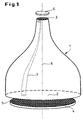
- the basic structure of the optical measuring system can be seen in FIG. 1.
- the most important component is the glass fiber taper element 1 with a large area End face 2 and a small-area end face 3.
- the large end face 2 stands a planar carrier 4 with the test objects 5 arranged thereon and the small one Face 3 an image sensor 6 for detecting and processing the reduced Image of the carrier surface with the test objects 5 opposite.
- the taper element 1 has approximately a bell-shaped contour.
- the individual glass fibers 7 are both on the large end face 2 and on the small end face 3 parallel to the optical axis 8 and thus perpendicular to the respective surfaces 2 and 3 oriented.
- a pivotable luminescence measuring system is shown.
- Carrier 4 a microtiter plate with test holes 9 for those to be examined Objects 5.
- the measuring system essentially consists of the microtiter plate 4, the Glass fiber taper element 1, an image intensifier 10 and a CCD camera 11. Das whole system is pivotable about a horizontal axis of rotation 12 on a fixed Frame 13 attached.
- the taper element 1 is in a light-tight housing 14 housed.
- 2a corresponds to the basic position, at the microtiter plate 4 as the bottom component and the optical elements 1,10,11 are arranged above it. This position corresponds to the so-called TOP measuring position.
- the whole system is in the position according to FIG.
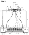
- FIG. 3 The actual structure of the optical system can be seen in FIG. 3, in which again the TOP position is shown.
- the glass fiber entry window 15 on the image intensifier 10 with the small area Front 3 of the taper element 1 are brought into contact to a efficient transfer of the taper output photons to the photocathode 16 to ensure the image intensifier 10.
- the gap 17 between the taper element 1 and the entrance window 15 can pass through Adjusting screws 18 on the camera support plate 19 in the z direction at zero distance to be brought. This minimizes a spreading that is introduced into the gap 17 Oil drops 20 the reflection losses by adjusting the refractive index at Transition from taper element 1 to detection system 10, 11. The oil has in this Case the same refractive index as the glass of the taper element 1. With the locking screws 21 becomes a rigid connection that is light-tight via a light trap 22 produced between the taper element 1 and the image intensifier 10.
- the microtiter plate 4 (see also FIG. 4) has a multiplicity of cylindrical or rectangular ones Test holes 9 (so-called wells) for receiving the luminescent biological objects 5 on.
- the bottom 23 of the microtiter plate 4 is a special version for the BOTTOM arrangement (according to FIG. 2b) made of an optically transparent material.
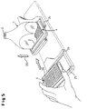
- the microtiter plate 4 is loaded into the measuring apparatus with the help of an extendable drawer 24, which is designed so that it at least for the BOTTOM measuring method in an open frame construction 25 the microtiter plates 4 can accommodate so that the actual measuring area is not covered becomes.
- an extendable drawer 24 which is designed so that it at least for the BOTTOM measuring method in an open frame construction 25 the microtiter plates 4 can accommodate so that the actual measuring area is not covered becomes.
- the drawer 24 is extended, the high voltage is interrupted of the image intensifier 10 coupled to prevent it from being destroyed by too much To protect light.
- retracting the microtiter plate 4 initially remains between its surface 26 and the large-area (lower here) taper surface 2 (see FIG. 3) a gap 27 of a few millimeters in order to hit when entering and thus to avoid possible damage to the taper surface 2.
- the microtiter plate surface 26 and the taper surface 2 in Be brought in contact This is done by means of a resilient height adjustment 29 (only schematically indicated in FIGS. 3 and 5), with which the microtiter plate 4 against the taper element 1 is raised after the microtiter plate 4 is exactly under the large end face 2 of the taper element 1 was positioned, but after exceeding yields to a defined pressure force.
- a resilient height adjustment 29 (only schematically indicated in FIGS. 3 and 5), with which the microtiter plate 4 against the taper element 1 is raised after the microtiter plate 4 is exactly under the large end face 2 of the taper element 1 was positioned, but after exceeding yields to a defined pressure force.
- the bottom of the housing part 30 enclosing the drawer 24 contains an opening closable with a blind plate 31 (see FIG. 3).
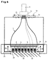
- the blind plate is removed and replaced by a window 32.
- this window can be in the TOP measuring position at an oblique angle of incidence Fluorescence excitation light 33 is irradiated to examine fluorescent objects to be able to.
- the bottom 23 of the microtiter plate 4 also optically transparent. Between the large end face 2 of the taper element 1 and the microtiter plate 4 is a replaceable, large-area for the fluorescent light selective interference filter 34 arranged to radiate interference from the excitation light 33 suppress.
- the apparatus described can thus quickly and easily from a luminescence measuring system to a fluorescence measuring system with the same high sensitivity.
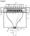
- FIG. 7 Another possibility for expanding the luminescence measuring system is shown in FIG. 7.
- the apparatus pivoted here into the BOTTOM measuring position is additional equipped with a micropipetting system 35, which is above the microtiter plate 4 is arranged.
- the individual pipettes 36 are the individual test holes 9 (wells) assigned to the microtiter plate 4.
- the drawer-like holder 24 for the microtiter plate 4 is like the previously described embodiment with a frame 25 (see Fig. 5) provided so that the top of the microtiter plate 4 for the micropipetting system 35 and the underside accessible for the observation of the luminescence is.
- the bottom 23 of the microtiter plate 4 in turn consists of a optically transparent material to the luminescence radiation of the samples 5 from the Observe the bottom through the bottom 23.
Abstract
Description
- Im Vergleich zu herkömmlichen Mikrotiterplatten-Lumineszenzmeßsystemen ist das neue System um den Faktor 10 lichtempfindlicher. Auf diese Weise sind sehr lichtschwache biolumineszente Reaktionen überhaupt erst nachweisbar.
- Bei gleichem Signal/Rausch-Verhältnis läßt sich die Integrationszeit um den Faktor 10 erniedrigen. Alternativ kann bei gleichem Signal/Rausch-Verhältnis die Menge der biologischen Objekte (z.B. die Zellzahl/Mikrotiterplatten) um den Faktor 10 vermindert werden oder umgekehrt bei gleicher Substratmenge der Probendurchsatz um den Faktor 10 vergrößert werden.
- Bei gleichem Signal/Rausch-Verhältnis kann die Substratmenge, die in einer bio-chemischen Reaktion die zu detektierenden Photonen freisetzt, um den Faktor 10 erniedrigt werden.
- Bei gleichem Signal/Rausch-Verhältnis kann wegen der hohen Empfindlichkeit die Fluoreszenzfarbstoffkonzentration um den Faktor 10 gesenkt (Verringerung der Nebenwirkung auf das biologische System) bzw. die Meßzeiten um den Faktor 10 gekürzt (Reduzierung der Ausbleicheffekte) werden.
- Aufgrund der senkrechten Lichterfassung der Taperoptik an der Mikrotiterplatte treten keine Vignettierungseffekte auf.
- Aufgrund des kleinen Aufbaus des Systems infolge der geringen Bauhöhe der Taperoptik von ca. 16 cm im Vergleich zum Abstand bei der Linsenabbildung von ca. 70 cm läßt sich ein Wechsel von einem Aufsicht- zu einem Durchsicht-Meßverfahren ohne Umbauarbeiten durch eine 180°- Drehung des Systems um die Schwerpunktachse realisieren.
- Fig. 1
- den prinzipiellen Aufbau des optischen Meßsystems
- Fig.2a
- eine schematische Ansicht eines Lumineszenzmeßsystems in der Grundstellung (TOP-Stellung)
- Fig. 2b
- eine schematische Ansicht des Lumineszenzmeßsystems in einer gegenüber
- Fig. 2a
- um 180 ° gedrehten Stellung (BOTTOM-Stellung)
- Fig. 3
- den Aufbau des Meßsystems für lumineszente biologische Objekte
- Fig. 4
- eine Draufsicht einer Mikrotiterplatte
- Fig. 5
- die schubladenartige Halterung für die Mikrotiterplatte
- Fig. 6
- den prinzipiellen Aufbau eines Meßsystems zur Untersuchung fluoreszierender biologischer Objekte mit schräg einfallendem Anregungslicht
- Fig. 7
- den prinzipiellen Aufbau eines Lumineszenzmeßsystems in der BOTTOM-Stellung mit einer Pipettiereinrichtung zur Untersuchung dynamischer Vorgänge bei lumineszenten biologischen Objekten
Claims (9)
- Meßsystem zur Detektion optischer Signale von Mikroassays, bei dem die signalgebenden Testobjekte (5) auf einer Untersuchungsfläche eines planen Trägers (4) angeordnet sind, bestehend aus einer Abbildungsoptik, die die zu vermessenden Testobjekte (4) derart verkleinert, daß alle Objekte auf einem zweidimensionalen, lichtempfindlichen Bildsensor (6) vollständig abgebildet werden, dadurch gekennzeichnet, daß die Abbildungsoptik aus einem hochauflösenden Glasfaser-Taperelement (1) mit einer großflächigen (2) und einer kleinflächigen Stirnseite (3) besteht und die Stirnseitenflächen (2,3) so gewählt sind, daß die großflächige Stirnfläche (2) mindestens der Untersuchungsfläche des Trägers (4) und die kleinflächige Stirnfläche (3) der Größe des Bildsensors (6) entspricht, wobei sich aus dem Verhältnis der Stirnflächen (2,3) der Verkleinerungsmaßstab der Abbildungsoptik ergibt, um die Untersuchungsfläche des Trägers (4) vollständig auf den Bildsensor (6) abzubilden.
- Meßsystem nach Anspruch 1, dadurch gekennzeichnet, daß der plane Träger aus einer Mikrotiterplatte (4) mit einer Vielzähl von Löchern (9) zur Aufnahme der signalgebenden Testobjekte (5) besteht, daß der Bildsensor (6) einen Bildverstärker (10) und eine Videokamera (11) zur Umwandlung der verstärkten Bildsignale in elektronische Signale umfaßt, und daß das Glasfaser-Taperelement (1) ein das Eintrittsfenster (15) des Bildverstärkers (10) voll ausfüllendes verkleinertes Bild der Mikrotiterplatte (4) erzeugt.
- Meßsystem nach Anspruch 1 bis 2, dadurch gekennzeichnet, daß der Bildverstärker (10) eine Bialkaliphotokathode aufweist, dessen spektrale Empfindlichkeit bei Wellenlängen > 700 nm < 1 % ist.
- Meßsystem nach Anspruch 1 bis 3, dadurch gekennzeichnet, daß die Mikrotiterplatte (4) in einer horizontal verfahrbaren und vertikal verstellbaren, schubladenartigen Halterung (24) angeordnet ist, die nach dem horizontalen Einfahren so weit angehoben wird, daß das Glasfaser-Taperelement (1) mit seiner großflächigen Stirnseite (2) in direktem Kontakt mit der Oberfläche der Mlkrotiterplatte (4) steht.
- Meßsystem nach Anspruch 1 bis 4, dadurch gekennzeichnet, daß die kleinflächige Stirnseite (3) des Glasfaser-Taperelements (1) in direktem optischen Kontakt mit dem Eintrittsfenster (15) des Bildverstärkers (10) steht.
- Meßsystem nach Anspruch 1 bis 5, dadurch gekennzeichnet, daß das Eintrittsfenster (15) des Bildverstärkers (10) durch eine Glasfaserplatte gebildet wird, die das Bild direkt auf die dahinterliegende Photokathode (16) des Bildverstärkers (10) überträgt.
- Meßsystem nach Anspruch 5 bis 6, dadurch gekennzeichnet, daß zur Minimierung von Reflexionsverlusten ein zwischen dem Glasfaser-Taperelement (1) und dem Eintrittsfenster (15) des Bildverstärkers (10) verbleibender Luftspalt (17) mit einem Ölfilm (20) ausgefüllt ist, dessen Brechungsindex mit dem Brechungsindex des Taperelements (1) übereinstimmt.
- Meßsystem nach Anspruch 1 bis 7, dadurch gekennzeichnet, daß die Mikrotiterplatte (4) einen optisch transparenten Boden (23) besitzt, daß die schubladenartige Halterung (24) als Rahmenkonstruktion (25) ausgebildet ist und daß unterhalb der Mikrotiterplatte (4) eine Lichtquelle zur Fluoreszenzanregung angeordnet ist, die ein zur optischen Achse schräg einfallendes Lichtbündel (33) erzeugt.
- Meßsystem nach Anspruch 1 bis 7, dadurch gekennzeichnet, daß die gesamte Apparatur um eine horizontale Achse (12) um 180° schwenkbar ist und folgende weitere Merkmale aufweist:a) Die Mikrotiterplatte (4) besitzt einen optisch transparenten Boden (23).b) Die schubladenartige Halterung (24) für die Mikrotiterplatte (4) ist als Rahmenkonstruktion (25) ausgebildet.c) Das Meßsystem weist zusätzlich ein Mikropipettiersystem (35) auf, dessen Einzelpipetten (36) den Testlöchern (9) in der Mikrotiterplatte (4) zugeordnet sind.
Applications Claiming Priority (2)
| Application Number | Priority Date | Filing Date | Title |
|---|---|---|---|
| DE19745373A DE19745373A1 (de) | 1997-10-14 | 1997-10-14 | Optisches Meßsystem zur Erfassung von Lumineszenz- oder Fluoreszenzsignalen |
| DE19745373 | 1997-10-14 |
Publications (3)
| Publication Number | Publication Date |
|---|---|
| EP0909947A2 true EP0909947A2 (de) | 1999-04-21 |
| EP0909947A3 EP0909947A3 (de) | 1999-06-09 |
| EP0909947B1 EP0909947B1 (de) | 2003-07-09 |
Family
ID=7845519
Family Applications (1)
| Application Number | Title | Priority Date | Filing Date |
|---|---|---|---|
| EP98118580A Expired - Lifetime EP0909947B1 (de) | 1997-10-14 | 1998-10-01 | Optisches Messsystem zur Erfassung von Lumineszenz-oder Fluoreszenz-signalen |
Country Status (10)
| Country | Link |
|---|---|
| US (1) | US6191852B1 (de) |
| EP (1) | EP0909947B1 (de) |
| JP (1) | JP4445596B2 (de) |
| AT (1) | ATE244882T1 (de) |
| CA (1) | CA2249908C (de) |
| DE (2) | DE19745373A1 (de) |
| DK (1) | DK0909947T3 (de) |
| ES (1) | ES2202710T3 (de) |
| IL (1) | IL126506A (de) |
| PT (1) | PT909947E (de) |
Cited By (6)
| Publication number | Priority date | Publication date | Assignee | Title |
|---|---|---|---|---|
| EP1305569A1 (de) * | 2000-05-22 | 2003-05-02 | Lockheed Martin Corporation | Positionsmessungsmodul mit faseroptischer verjüngungskopplung |
| GB2390155A (en) * | 2001-01-03 | 2003-12-31 | Packard Instrument Co Inc | System for measuring fluorescence and luminescence |
| EP2843392A3 (de) * | 2013-09-02 | 2015-03-11 | Roche Diagnostics GmbH | Vorrichtung zur fotometrischen Messung von biologischen Flüssigkeiten |
| JP2016515207A (ja) * | 2013-03-14 | 2016-05-26 | ジェン−プローブ・インコーポレーテッド | 複数の蛍光源からの信号放出を検出するための装置 |
| DE102016201440A1 (de) | 2016-02-01 | 2017-08-03 | Carl Zeiss Microscopy Gmbh | Bilderfassungsvorrichtung einer Mikroskopanordnung, Mikroskopanordnung und Mikroskopieverfahren |
| DE102019128546A1 (de) * | 2019-10-22 | 2021-04-22 | Byonoy Gmbh | Transmissionsvorrichtung zur Untersuchung von Proben in Kavitäten einer Mikrotiterplatte und Verfahren zum Untersuchen von Proben in Kavitäten einer Mikrotiterplatte mittels Transmission |
Families Citing this family (119)
| Publication number | Priority date | Publication date | Assignee | Title |
|---|---|---|---|---|
| WO1998001744A1 (en) * | 1996-07-10 | 1998-01-15 | Cambridge Imaging Limited | Improved imaging system for fluorescence assays |
| US6036924A (en) | 1997-12-04 | 2000-03-14 | Hewlett-Packard Company | Cassette of lancet cartridges for sampling blood |
| US6391005B1 (en) | 1998-03-30 | 2002-05-21 | Agilent Technologies, Inc. | Apparatus and method for penetration with shaft having a sensor for sensing penetration depth |
| US6096205A (en) * | 1998-05-13 | 2000-08-01 | The Regents Of The University Of California | Hand portable thin-layer chromatography system |
| US7510841B2 (en) * | 1998-12-28 | 2009-03-31 | Illumina, Inc. | Methods of making and using composite arrays for the detection of a plurality of target analytes |
| DE19919092A1 (de) * | 1999-04-27 | 2000-11-02 | Zeiss Carl Jena Gmbh | Anordnung zur optischen Auswertung eines Gegenstandsarrays |
| DE19919539C5 (de) * | 1999-04-29 | 2004-12-09 | Gerhard Lewandovski | Verfahren zur Messung der Aktivität einer biologisch wirksamen Substanz in einem histologischen Präparat |
| US6527708B1 (en) * | 1999-07-02 | 2003-03-04 | Pentax Corporation | Endoscope system |
| DE19930607C2 (de) * | 1999-07-02 | 2002-08-01 | Max Planck Gesellschaft | Verfahren zur Gewinnung von Daten, die Aufschluß geben über die Kinetik der Reaktionen von Reaktanten in einer Vielzahl von Proben und Vorrichtung zur Durchführung des Verfahrens |
| WO2001007896A1 (en) * | 1999-07-21 | 2001-02-01 | Tropix, Inc. | Luminescence detection workstation |
| DE19935433A1 (de) * | 1999-08-01 | 2001-03-01 | Febit Ferrarius Biotech Gmbh | Mikrofluidischer Reaktionsträger |
| DE19936999C2 (de) * | 1999-08-02 | 2002-03-14 | Jena Optronik Gmbh | Anordnung zum Erfassen der Fluoreszenzstrahlung von matrixförmigen Probenträgern |
| US6770441B2 (en) * | 2000-02-10 | 2004-08-03 | Illumina, Inc. | Array compositions and methods of making same |
| US6627159B1 (en) * | 2000-06-28 | 2003-09-30 | 3M Innovative Properties Company | Centrifugal filling of sample processing devices |
| US8097471B2 (en) * | 2000-11-10 | 2012-01-17 | 3M Innovative Properties Company | Sample processing devices |
| US8641644B2 (en) | 2000-11-21 | 2014-02-04 | Sanofi-Aventis Deutschland Gmbh | Blood testing apparatus having a rotatable cartridge with multiple lancing elements and testing means |
| US7025774B2 (en) | 2001-06-12 | 2006-04-11 | Pelikan Technologies, Inc. | Tissue penetration device |
| US9795747B2 (en) | 2010-06-02 | 2017-10-24 | Sanofi-Aventis Deutschland Gmbh | Methods and apparatus for lancet actuation |
| US7682318B2 (en) | 2001-06-12 | 2010-03-23 | Pelikan Technologies, Inc. | Blood sampling apparatus and method |
| US7981056B2 (en) * | 2002-04-19 | 2011-07-19 | Pelikan Technologies, Inc. | Methods and apparatus for lancet actuation |
| US8337419B2 (en) | 2002-04-19 | 2012-12-25 | Sanofi-Aventis Deutschland Gmbh | Tissue penetration device |
| US7749174B2 (en) | 2001-06-12 | 2010-07-06 | Pelikan Technologies, Inc. | Method and apparatus for lancet launching device intergrated onto a blood-sampling cartridge |
| DE60234598D1 (de) | 2001-06-12 | 2010-01-14 | Pelikan Technologies Inc | Selbstoptimierende lanzettenvorrichtung mit adaptationsmittel für zeitliche schwankungen von hauteigenschaften |
| EP1404234B1 (de) | 2001-06-12 | 2011-02-09 | Pelikan Technologies Inc. | Gerät zur erhöhung der erfolgsrate im hinblick auf die durch einen fingerstich erhaltene blutausbeute |
| US9427532B2 (en) | 2001-06-12 | 2016-08-30 | Sanofi-Aventis Deutschland Gmbh | Tissue penetration device |
| US9226699B2 (en) | 2002-04-19 | 2016-01-05 | Sanofi-Aventis Deutschland Gmbh | Body fluid sampling module with a continuous compression tissue interface surface |
| ATE485766T1 (de) | 2001-06-12 | 2010-11-15 | Pelikan Technologies Inc | Elektrisches betätigungselement für eine lanzette |
| DE10131687A1 (de) * | 2001-06-29 | 2003-01-16 | Eppendorf Ag | Vorrichtung zur Durchführung von Nukleinsäure-Amplifikationsreaktionen bei gleichzeitiger Verfolgung der Bildung von Amplifikationsprodukten |
| DE10145221A1 (de) * | 2001-09-13 | 2003-04-10 | Lavision Biotec Gmbh | Verfahren zur Anregung und Detektion von Fluoreszenzen von Mikroarrays |
| US7648468B2 (en) | 2002-04-19 | 2010-01-19 | Pelikon Technologies, Inc. | Method and apparatus for penetrating tissue |
| US7371247B2 (en) | 2002-04-19 | 2008-05-13 | Pelikan Technologies, Inc | Method and apparatus for penetrating tissue |
| US7717863B2 (en) | 2002-04-19 | 2010-05-18 | Pelikan Technologies, Inc. | Method and apparatus for penetrating tissue |
| US9248267B2 (en) | 2002-04-19 | 2016-02-02 | Sanofi-Aventis Deustchland Gmbh | Tissue penetration device |
| US7175642B2 (en) | 2002-04-19 | 2007-02-13 | Pelikan Technologies, Inc. | Methods and apparatus for lancet actuation |
| US8784335B2 (en) | 2002-04-19 | 2014-07-22 | Sanofi-Aventis Deutschland Gmbh | Body fluid sampling device with a capacitive sensor |
| US7582099B2 (en) * | 2002-04-19 | 2009-09-01 | Pelikan Technologies, Inc | Method and apparatus for penetrating tissue |
| US7291117B2 (en) | 2002-04-19 | 2007-11-06 | Pelikan Technologies, Inc. | Method and apparatus for penetrating tissue |
| US8360992B2 (en) | 2002-04-19 | 2013-01-29 | Sanofi-Aventis Deutschland Gmbh | Method and apparatus for penetrating tissue |
| US8221334B2 (en) | 2002-04-19 | 2012-07-17 | Sanofi-Aventis Deutschland Gmbh | Method and apparatus for penetrating tissue |
| US7491178B2 (en) | 2002-04-19 | 2009-02-17 | Pelikan Technologies, Inc. | Method and apparatus for penetrating tissue |
| US7229458B2 (en) * | 2002-04-19 | 2007-06-12 | Pelikan Technologies, Inc. | Method and apparatus for penetrating tissue |
| US7892185B2 (en) | 2002-04-19 | 2011-02-22 | Pelikan Technologies, Inc. | Method and apparatus for body fluid sampling and analyte sensing |
| US9314194B2 (en) | 2002-04-19 | 2016-04-19 | Sanofi-Aventis Deutschland Gmbh | Tissue penetration device |
| US7909778B2 (en) | 2002-04-19 | 2011-03-22 | Pelikan Technologies, Inc. | Method and apparatus for penetrating tissue |
| US8267870B2 (en) | 2002-04-19 | 2012-09-18 | Sanofi-Aventis Deutschland Gmbh | Method and apparatus for body fluid sampling with hybrid actuation |
| US7976476B2 (en) | 2002-04-19 | 2011-07-12 | Pelikan Technologies, Inc. | Device and method for variable speed lancet |
| US9795334B2 (en) | 2002-04-19 | 2017-10-24 | Sanofi-Aventis Deutschland Gmbh | Method and apparatus for penetrating tissue |
| US8579831B2 (en) | 2002-04-19 | 2013-11-12 | Sanofi-Aventis Deutschland Gmbh | Method and apparatus for penetrating tissue |
| US7547287B2 (en) | 2002-04-19 | 2009-06-16 | Pelikan Technologies, Inc. | Method and apparatus for penetrating tissue |
| US7901362B2 (en) | 2002-04-19 | 2011-03-08 | Pelikan Technologies, Inc. | Method and apparatus for penetrating tissue |
| US7674232B2 (en) | 2002-04-19 | 2010-03-09 | Pelikan Technologies, Inc. | Method and apparatus for penetrating tissue |
| US7232451B2 (en) | 2002-04-19 | 2007-06-19 | Pelikan Technologies, Inc. | Method and apparatus for penetrating tissue |
| US7226461B2 (en) | 2002-04-19 | 2007-06-05 | Pelikan Technologies, Inc. | Method and apparatus for a multi-use body fluid sampling device with sterility barrier release |
| US7297122B2 (en) | 2002-04-19 | 2007-11-20 | Pelikan Technologies, Inc. | Method and apparatus for penetrating tissue |
| US7892183B2 (en) | 2002-04-19 | 2011-02-22 | Pelikan Technologies, Inc. | Method and apparatus for body fluid sampling and analyte sensing |
| US7331931B2 (en) * | 2002-04-19 | 2008-02-19 | Pelikan Technologies, Inc. | Method and apparatus for penetrating tissue |
| US8702624B2 (en) | 2006-09-29 | 2014-04-22 | Sanofi-Aventis Deutschland Gmbh | Analyte measurement device with a single shot actuator |
| FI116422B (fi) * | 2002-07-30 | 2005-11-15 | Hidex Oy | Monitoiminen mittausinstrumentti |
| DE10237400A1 (de) * | 2002-08-09 | 2004-03-11 | Siemens Ag | Gehäuse zur Probenbeaufschlagung von Beads |
| US7507376B2 (en) * | 2002-12-19 | 2009-03-24 | 3M Innovative Properties Company | Integrated sample processing devices |
| US8574895B2 (en) | 2002-12-30 | 2013-11-05 | Sanofi-Aventis Deutschland Gmbh | Method and apparatus using optical techniques to measure analyte levels |
| DE10322443A1 (de) * | 2003-05-19 | 2004-12-30 | PRO DESIGN Gesellschaft für Produktentwicklung mbH | Multifunktioneller Reader für Biochips |
| EP1628567B1 (de) | 2003-05-30 | 2010-08-04 | Pelikan Technologies Inc. | Verfahren und vorrichtung zur injektion von flüssigkeit |
| DK1633235T3 (da) | 2003-06-06 | 2014-08-18 | Sanofi Aventis Deutschland | Apparat til udtagelse af legemsvæskeprøver og detektering af analyt |
| WO2006001797A1 (en) | 2004-06-14 | 2006-01-05 | Pelikan Technologies, Inc. | Low pain penetrating |
| US8282576B2 (en) | 2003-09-29 | 2012-10-09 | Sanofi-Aventis Deutschland Gmbh | Method and apparatus for an improved sample capture device |
| EP1680014A4 (de) | 2003-10-14 | 2009-01-21 | Pelikan Technologies Inc | Verfahren und gerät für eine variable anwenderschnittstelle |
| US7822454B1 (en) | 2005-01-03 | 2010-10-26 | Pelikan Technologies, Inc. | Fluid sampling device with improved analyte detecting member configuration |
| EP1706026B1 (de) | 2003-12-31 | 2017-03-01 | Sanofi-Aventis Deutschland GmbH | Verfahren und vorrichtung zur verbesserung der fluidströmung und der probennahme |
| US8828203B2 (en) | 2004-05-20 | 2014-09-09 | Sanofi-Aventis Deutschland Gmbh | Printable hydrogels for biosensors |
| EP1765194A4 (de) | 2004-06-03 | 2010-09-29 | Pelikan Technologies Inc | Verfahren und gerät für eine flüssigkeitsentnahmenvorrichtung |
| US9775553B2 (en) | 2004-06-03 | 2017-10-03 | Sanofi-Aventis Deutschland Gmbh | Method and apparatus for a fluid sampling device |
| US7932090B2 (en) * | 2004-08-05 | 2011-04-26 | 3M Innovative Properties Company | Sample processing device positioning apparatus and methods |
| US8652831B2 (en) | 2004-12-30 | 2014-02-18 | Sanofi-Aventis Deutschland Gmbh | Method and apparatus for analyte measurement test time |
| JP5123660B2 (ja) * | 2005-03-30 | 2013-01-23 | オリンパス株式会社 | 測定装置 |
| US20060246576A1 (en) * | 2005-04-06 | 2006-11-02 | Affymetrix, Inc. | Fluidic system and method for processing biological microarrays in personal instrumentation |
| CA2603927A1 (en) * | 2005-04-08 | 2006-10-19 | Chemimage Corporation | System and method for chemical imaging of microarrays |
| DE102005027555B3 (de) * | 2005-06-14 | 2006-10-05 | Eppendorf Ag | Thermocycler |
| US9528939B2 (en) | 2006-03-10 | 2016-12-27 | Indx Lifecare, Inc. | Waveguide-based optical scanning systems |
| US9423397B2 (en) | 2006-03-10 | 2016-08-23 | Indx Lifecare, Inc. | Waveguide-based detection system with scanning light source |
| US9976192B2 (en) | 2006-03-10 | 2018-05-22 | Ldip, Llc | Waveguide-based detection system with scanning light source |
| US8288157B2 (en) * | 2007-09-12 | 2012-10-16 | Plc Diagnostics, Inc. | Waveguide-based optical scanning systems |
| US20080003667A1 (en) * | 2006-05-19 | 2008-01-03 | Affymetrix, Inc. | Consumable elements for use with fluid processing and detection systems |
| JP2007333650A (ja) * | 2006-06-16 | 2007-12-27 | Hamamatsu Photonics Kk | 光検出装置 |
| US7856161B2 (en) * | 2007-03-21 | 2010-12-21 | Schott Corporation | Optical fiber faceplates including convergent constituent imaging conduits and tiled imaging arrays incorporating the same |
| AU2008308686B2 (en) | 2007-10-02 | 2015-01-22 | Labrador Diagnostics Llc | Modular point-of-care devices and uses thereof |
| GB0802568D0 (en) * | 2008-02-12 | 2008-03-19 | Optima Design Services Ltd | Particle separation apparatus and methods |
| WO2009126900A1 (en) | 2008-04-11 | 2009-10-15 | Pelikan Technologies, Inc. | Method and apparatus for analyte detecting device |
| GB2461026B (en) * | 2008-06-16 | 2011-03-09 | Plc Diagnostics Inc | System and method for nucleic acids sequencing by phased synthesis |
| WO2010081536A1 (en) * | 2009-01-13 | 2010-07-22 | Bcs Biotech S.P.A. | A biochip reader for qualitative and quantitative analysis of images, in particular for the analysis of single or multiple biochips |
| US9375169B2 (en) | 2009-01-30 | 2016-06-28 | Sanofi-Aventis Deutschland Gmbh | Cam drive for managing disposable penetrating member actions with a single motor and motor and control system |
| CN102460254B (zh) * | 2009-04-29 | 2015-05-06 | Plc诊断股份有限公司 | 具有扫描光源的基于波导的检测系统 |
| US8965476B2 (en) | 2010-04-16 | 2015-02-24 | Sanofi-Aventis Deutschland Gmbh | Tissue penetration device |
| JP2011257216A (ja) * | 2010-06-08 | 2011-12-22 | Konica Minolta Holdings Inc | 表面プラズモン増強蛍光センサおよび表面プラズモン増強蛍光センサに用いられるチップ構造体ユニット |
| JP2012063238A (ja) * | 2010-09-16 | 2012-03-29 | Database Co Ltd | 表面プラズモン共鳴現象測定装置および測定方法 |
| AR085087A1 (es) | 2011-01-21 | 2013-09-11 | Theranos Inc | Sistemas y metodos para maximizar el uso de muestras |
| US9619627B2 (en) | 2011-09-25 | 2017-04-11 | Theranos, Inc. | Systems and methods for collecting and transmitting assay results |
| US8475739B2 (en) | 2011-09-25 | 2013-07-02 | Theranos, Inc. | Systems and methods for fluid handling |
| US9268915B2 (en) | 2011-09-25 | 2016-02-23 | Theranos, Inc. | Systems and methods for diagnosis or treatment |
| US20140170735A1 (en) | 2011-09-25 | 2014-06-19 | Elizabeth A. Holmes | Systems and methods for multi-analysis |
| US8840838B2 (en) | 2011-09-25 | 2014-09-23 | Theranos, Inc. | Centrifuge configurations |
| US9664702B2 (en) | 2011-09-25 | 2017-05-30 | Theranos, Inc. | Fluid handling apparatus and configurations |
| US9632102B2 (en) | 2011-09-25 | 2017-04-25 | Theranos, Inc. | Systems and methods for multi-purpose analysis |
| US9810704B2 (en) | 2013-02-18 | 2017-11-07 | Theranos, Inc. | Systems and methods for multi-analysis |
| US9250229B2 (en) | 2011-09-25 | 2016-02-02 | Theranos, Inc. | Systems and methods for multi-analysis |
| US10012664B2 (en) | 2011-09-25 | 2018-07-03 | Theranos Ip Company, Llc | Systems and methods for fluid and component handling |
| US9618455B2 (en) * | 2012-08-20 | 2017-04-11 | Siemens Healthcare Diagnostics Inc. | Clam-shell luminometer |
| US10422806B1 (en) | 2013-07-25 | 2019-09-24 | Theranos Ip Company, Llc | Methods for improving assays of biological samples |
| US10018566B2 (en) | 2014-02-28 | 2018-07-10 | Ldip, Llc | Partially encapsulated waveguide based sensing chips, systems and methods of use |
| GB2548763B (en) | 2015-02-02 | 2021-07-21 | Hitachi High Tech Corp | Multicolor fluorescence analysis device |
| US11181479B2 (en) | 2015-02-27 | 2021-11-23 | Ldip, Llc | Waveguide-based detection system with scanning light source |
| CA3170197A1 (en) * | 2015-06-09 | 2016-12-15 | Gen-Probe Incorporated | Methods and devices for calibrating and/or monitoring optical measurement devices |
| DE102016225817B4 (de) | 2016-12-21 | 2019-07-04 | Bayer Pharma Aktiengesellschaft | Verfahren und System für Messungen im Hochdurchsatz-Screening mit hoher Zeitauflösung |
| DE102017007176A1 (de) * | 2017-08-01 | 2019-02-07 | Fagus-Grecon Greten Gmbh & Co. Kg | Optische Detektorvorrichtung |
| US10859505B2 (en) * | 2018-01-26 | 2020-12-08 | Gemological Institute Of America, Inc. (Gia) | Fluorescence box for gemological applications |
| CN109632098B (zh) * | 2019-01-18 | 2021-06-11 | 陈岱晴 | 小型发光体空间光辐射测量方法、系统以及光纤传像束 |
| CN110132896A (zh) * | 2019-05-06 | 2019-08-16 | 山西大学 | 一种快速检测血清中乳腺癌标志物的微型光纤生物传感器 |
| WO2021178889A1 (en) * | 2020-03-05 | 2021-09-10 | The Trustees Of Columbia University In The City Of New York | Three-dimensional dosimetry procedures, methods and devices, and optical ct scanner apparatus which utilizes fiber optic taper for collimated images |
| CN113432833B (zh) * | 2021-06-15 | 2022-09-16 | 北方夜视技术股份有限公司 | 用于测试像增强管光电阴极光照后稳定性的装置及方法 |
Citations (7)
| Publication number | Priority date | Publication date | Assignee | Title |
|---|---|---|---|---|
| US3101411A (en) * | 1960-05-17 | 1963-08-20 | American Optical Corp | Light conducting device to transmit ultra-violet radiation for specimen fluorescenceunder a microscope |
| JPS63298137A (ja) * | 1987-05-29 | 1988-12-05 | Soken:Kk | イメ−ジファイバを用いた検体分析装置 |
| US4922092A (en) * | 1986-11-26 | 1990-05-01 | Image Research Limited | High sensitivity optical imaging apparatus |
| US5247392A (en) * | 1991-05-21 | 1993-09-21 | Siemens Aktiengesellschaft | Objective lens for producing a radiation focus in the inside of a specimen |
| US5347122A (en) * | 1989-12-08 | 1994-09-13 | Cambridge Imaging Limited | Light transmission system with photon transfer to an optical detector and cell investigation techniques using the light transmission system |
| GB2315131A (en) * | 1996-07-10 | 1998-01-21 | Cambridge Imaging Ltd | Fibre optic coupling plate for checking fluorescence in a sample |
| WO1998023945A1 (en) * | 1996-11-27 | 1998-06-04 | Optical Analytic Inc. | Perimeter light detection apparatus for enhanced collection of radiation |
Family Cites Families (13)
| Publication number | Priority date | Publication date | Assignee | Title |
|---|---|---|---|---|
| JPS5510172B2 (de) | 1975-02-14 | 1980-03-14 | ||
| EP0025350A3 (de) * | 1979-09-05 | 1981-06-10 | Dynatech Ag | Apparat zum Feststellen von Lumineszenz-Reaktionen |
| US4554839A (en) * | 1983-10-14 | 1985-11-26 | Cetus Corporation | Multiple trough vessel for automated liquid handling apparatus |
| EP0266881A3 (de) * | 1986-09-30 | 1990-04-04 | Astromed Limited | Verfahren und Vorrichtung für optische Mehrfachprüfung |
| DE3833064A1 (de) * | 1988-09-29 | 1990-04-05 | Dynatech Ag Branch Denkendorf | Leseeinheit fuer eine mikrotestplatte |
| DE3841961A1 (de) * | 1988-12-14 | 1990-06-21 | Dynatech Ag Branch Denkendorf | Geraet zur analyse von physiologischen oder anderen fluessigkeiten in den vertiefungen einer mikrotestplatte |
| JP2750605B2 (ja) * | 1989-05-17 | 1998-05-13 | スズキ株式会社 | 粒子凝集パターン判定方法 |
| JPH05157684A (ja) * | 1991-12-02 | 1993-06-25 | Seikagaku Kogyo Co Ltd | 吸光光度計 |
| US5635402A (en) * | 1992-03-05 | 1997-06-03 | Alfano; Robert R. | Technique for determining whether a cell is malignant as opposed to non-malignant using extrinsic fluorescence spectroscopy |
| JP3157601B2 (ja) * | 1992-04-27 | 2001-04-16 | オリンパス光学工業株式会社 | 自動血液分析機 |
| US5508200A (en) * | 1992-10-19 | 1996-04-16 | Tiffany; Thomas | Method and apparatus for conducting multiple chemical assays |
| US5686723A (en) | 1996-04-10 | 1997-11-11 | Hughes Electronics | Light sensing detector assembly with integral fiber optic light transmission elements |
| SE506755C2 (sv) * | 1996-04-15 | 1998-02-09 | Med Ai Europ Ab | Anordning för optisk analys av ett prov |
-
1997
- 1997-10-14 DE DE19745373A patent/DE19745373A1/de not_active Withdrawn
-
1998
- 1998-10-01 DK DK98118580T patent/DK0909947T3/da active
- 1998-10-01 EP EP98118580A patent/EP0909947B1/de not_active Expired - Lifetime
- 1998-10-01 AT AT98118580T patent/ATE244882T1/de active
- 1998-10-01 PT PT98118580T patent/PT909947E/pt unknown
- 1998-10-01 DE DE59808960T patent/DE59808960D1/de not_active Expired - Lifetime
- 1998-10-01 ES ES98118580T patent/ES2202710T3/es not_active Expired - Lifetime
- 1998-10-09 IL IL12650698A patent/IL126506A/en not_active IP Right Cessation
- 1998-10-09 JP JP30173998A patent/JP4445596B2/ja not_active Expired - Lifetime
- 1998-10-09 CA CA002249908A patent/CA2249908C/en not_active Expired - Lifetime
- 1998-10-13 US US09/170,482 patent/US6191852B1/en not_active Expired - Lifetime
Patent Citations (7)
| Publication number | Priority date | Publication date | Assignee | Title |
|---|---|---|---|---|
| US3101411A (en) * | 1960-05-17 | 1963-08-20 | American Optical Corp | Light conducting device to transmit ultra-violet radiation for specimen fluorescenceunder a microscope |
| US4922092A (en) * | 1986-11-26 | 1990-05-01 | Image Research Limited | High sensitivity optical imaging apparatus |
| JPS63298137A (ja) * | 1987-05-29 | 1988-12-05 | Soken:Kk | イメ−ジファイバを用いた検体分析装置 |
| US5347122A (en) * | 1989-12-08 | 1994-09-13 | Cambridge Imaging Limited | Light transmission system with photon transfer to an optical detector and cell investigation techniques using the light transmission system |
| US5247392A (en) * | 1991-05-21 | 1993-09-21 | Siemens Aktiengesellschaft | Objective lens for producing a radiation focus in the inside of a specimen |
| GB2315131A (en) * | 1996-07-10 | 1998-01-21 | Cambridge Imaging Ltd | Fibre optic coupling plate for checking fluorescence in a sample |
| WO1998023945A1 (en) * | 1996-11-27 | 1998-06-04 | Optical Analytic Inc. | Perimeter light detection apparatus for enhanced collection of radiation |
Non-Patent Citations (1)
| Title |
|---|
| PATENT ABSTRACTS OF JAPAN vol. 013, no. 127 (P-848), 29. März 1989 & JP 63 298137 A (SOKEN:KK), 5. Dezember 1988 * |
Cited By (10)
| Publication number | Priority date | Publication date | Assignee | Title |
|---|---|---|---|---|
| EP1305569A1 (de) * | 2000-05-22 | 2003-05-02 | Lockheed Martin Corporation | Positionsmessungsmodul mit faseroptischer verjüngungskopplung |
| EP1305569A4 (de) * | 2000-05-22 | 2005-08-03 | Lockheed Corp | Positionsmessungsmodul mit faseroptischer verjüngungskopplung |
| GB2390155A (en) * | 2001-01-03 | 2003-12-31 | Packard Instrument Co Inc | System for measuring fluorescence and luminescence |
| GB2390155B (en) * | 2001-01-03 | 2004-04-21 | Packard Instrument Co Inc | Luminescence imager |
| US6961125B2 (en) | 2001-01-03 | 2005-11-01 | Packard Instrument Company, Inc. | Luminescence imager |
| JP2016515207A (ja) * | 2013-03-14 | 2016-05-26 | ジェン−プローブ・インコーポレーテッド | 複数の蛍光源からの信号放出を検出するための装置 |
| EP2843392A3 (de) * | 2013-09-02 | 2015-03-11 | Roche Diagnostics GmbH | Vorrichtung zur fotometrischen Messung von biologischen Flüssigkeiten |
| US9115395B2 (en) | 2013-09-02 | 2015-08-25 | Roche Molecular Systems, Inc. | Apparatus for photometric measurement of biological liquids |
| DE102016201440A1 (de) | 2016-02-01 | 2017-08-03 | Carl Zeiss Microscopy Gmbh | Bilderfassungsvorrichtung einer Mikroskopanordnung, Mikroskopanordnung und Mikroskopieverfahren |
| DE102019128546A1 (de) * | 2019-10-22 | 2021-04-22 | Byonoy Gmbh | Transmissionsvorrichtung zur Untersuchung von Proben in Kavitäten einer Mikrotiterplatte und Verfahren zum Untersuchen von Proben in Kavitäten einer Mikrotiterplatte mittels Transmission |
Also Published As
| Publication number | Publication date |
|---|---|
| ES2202710T3 (es) | 2004-04-01 |
| US6191852B1 (en) | 2001-02-20 |
| JPH11241947A (ja) | 1999-09-07 |
| CA2249908C (en) | 2007-05-29 |
| EP0909947A3 (de) | 1999-06-09 |
| IL126506A0 (en) | 1999-08-17 |
| CA2249908A1 (en) | 1999-04-14 |
| EP0909947B1 (de) | 2003-07-09 |
| DE19745373A1 (de) | 1999-04-15 |
| DK0909947T3 (da) | 2003-10-27 |
| IL126506A (en) | 2002-05-23 |
| JP4445596B2 (ja) | 2010-04-07 |
| PT909947E (pt) | 2003-11-28 |
| DE59808960D1 (de) | 2003-08-14 |
| ATE244882T1 (de) | 2003-07-15 |
Similar Documents
| Publication | Publication Date | Title |
|---|---|---|
| EP0909947B1 (de) | Optisches Messsystem zur Erfassung von Lumineszenz-oder Fluoreszenz-signalen | |
| DE4438391C2 (de) | Vorrichtung zur Bestimmung stoffspezifischer Parameter eines oder weniger Moleküle mittels Korrelations-Spektroskopie | |
| DE60132656T2 (de) | Quantifizierte fluoreszenzmikroskopie | |
| DE602005002625T2 (de) | System und verfahren für mehrfach-laserauslösung | |
| DE112015000433B4 (de) | Probenhalter, Betrachtungssystem und Bilderzeugungsverfahren | |
| DE102015003019A1 (de) | Verfahren und Vorrichtung zur optischen Detektion einer Bewegung in einer biologischen Probe mit räumlicher Ausdehnung | |
| DE19748211A1 (de) | Optisches Array-System und Reader für Mikrotiterplatten | |
| DE19544501A1 (de) | Vorrichtung für Lichtreflexionsmessungen | |
| EP2377309B1 (de) | Spektralauflösende elektronische röntgenkamera | |
| DE102011117228A1 (de) | Mikroskopiesystem zur Zustandsbestimmung von Zellen | |
| EP3392650A1 (de) | Vorrichtung und verfahren zur spektroskopischen analyse | |
| DE102015004104A1 (de) | Verfahren zum Lokalisieren wenigstens eines Emitters míttels eines Lokalisationsmikroskops | |
| DE60015737T2 (de) | Probenabbildung | |
| DE10017824B4 (de) | Vorrichtung zur parallelen photometrischen Fluoreszenz- oder Lumineszenzanalyse mehrerer voneinander getrennter Probenbereiche auf einem Objekt | |
| WO2003098200A1 (de) | Vorrichtung und verfahren zur untersuchung chemischer und/oder biologischer proben | |
| WO1997040368A1 (de) | Bildaufnahmesystem zur auswertung analytischer testelemente | |
| DE69935595T2 (de) | Verbessertes abbildungssystem für lumineszierende assays | |
| DD227044B1 (de) | Vorrichtung zur erfassung des stoffwechselzustandes von lebenden organen | |
| DE102014224449A1 (de) | Szintillationsdetektor mit hoher Zählrate | |
| EP0916099B1 (de) | Röntgen- oder gamma-photonendetektoranordnung mit glasfaserkörper mit gekrümmter eingangsfläche | |
| DE102008001322A1 (de) | System zur optischen Analyse von Probenarrays | |
| DE112020006001T5 (de) | Ladungsträgerdetektor, ladungsträgerstrahlvorrichtung, strahlungsdetektor und strahlungsdetektionsvorrichtung | |
| DE102020108432A1 (de) | Vorrichtung und Verfahren zur Lumineszenzanalyse mehrerer Proben | |
| DE19843229A1 (de) | Verfahren und Gerät zum Analysieren von Proben mittels Röntgenfluoreszenz-Spektroskopie | |
| EP1446654A2 (de) | Verfahren und vorrichtung zur korrektur der grösse und/oder form eines messvolumens in einer chemischen und/oder biologischen probe |
Legal Events
| Date | Code | Title | Description |
|---|---|---|---|
| PUAI | Public reference made under article 153(3) epc to a published international application that has entered the european phase |
Free format text: ORIGINAL CODE: 0009012 |
|
| AK | Designated contracting states |
Kind code of ref document: A2 Designated state(s): AT BE CH CY DE DK ES FI FR GB GR IE IT LI LU MC NL PT SE |
|
| AX | Request for extension of the european patent |
Free format text: AL;LT;LV;MK;RO;SI |
|
| PUAL | Search report despatched |
Free format text: ORIGINAL CODE: 0009013 |
|
| AK | Designated contracting states |
Kind code of ref document: A3 Designated state(s): AT BE CH CY DE DK ES FI FR GB GR IE IT LI LU MC NL PT SE |
|
| AX | Request for extension of the european patent |
Free format text: AL;LT;LV;MK;RO;SI |
|
| 17P | Request for examination filed |
Effective date: 19991209 |
|
| AKX | Designation fees paid |
Free format text: AT BE CH CY DE DK ES FI FR GB GR IE IT LI LU MC NL PT SE |
|
| 17Q | First examination report despatched |
Effective date: 20011129 |
|
| GRAH | Despatch of communication of intention to grant a patent |
Free format text: ORIGINAL CODE: EPIDOS IGRA |
|
| GRAH | Despatch of communication of intention to grant a patent |
Free format text: ORIGINAL CODE: EPIDOS IGRA |
|
| GRAA | (expected) grant |
Free format text: ORIGINAL CODE: 0009210 |
|
| AK | Designated contracting states |
Designated state(s): AT BE CH CY DE DK ES FI FR GB GR IE IT LI LU MC NL PT SE |
|
| REG | Reference to a national code |
Ref country code: GB Ref legal event code: FG4D Free format text: NOT ENGLISH |
|
| REG | Reference to a national code |
Ref country code: CH Ref legal event code: NV Representative=s name: DR. R.C. SALGO EUROPEAN PATENT ATTORNEY Ref country code: CH Ref legal event code: EP |
|
| REF | Corresponds to: |
Ref document number: 59808960 Country of ref document: DE Date of ref document: 20030814 Kind code of ref document: P |
|
| REG | Reference to a national code |
Ref country code: IE Ref legal event code: FG4D Free format text: GERMAN |
|
| GBT | Gb: translation of ep patent filed (gb section 77(6)(a)/1977) | ||
| REG | Reference to a national code |
Ref country code: SE Ref legal event code: TRGR |
|
| REG | Reference to a national code |
Ref country code: GR Ref legal event code: EP Ref document number: 20030404081 Country of ref document: GR |
|
| ET | Fr: translation filed | ||
| REG | Reference to a national code |
Ref country code: ES Ref legal event code: FG2A Ref document number: 2202710 Country of ref document: ES Kind code of ref document: T3 |
|
| PLBE | No opposition filed within time limit |
Free format text: ORIGINAL CODE: 0009261 |
|
| STAA | Information on the status of an ep patent application or granted ep patent |
Free format text: STATUS: NO OPPOSITION FILED WITHIN TIME LIMIT |
|
| 26N | No opposition filed |
Effective date: 20040414 |
|
| PGFP | Annual fee paid to national office [announced via postgrant information from national office to epo] |
Ref country code: GR Payment date: 20040924 Year of fee payment: 7 |
|
| PGFP | Annual fee paid to national office [announced via postgrant information from national office to epo] |
Ref country code: PT Payment date: 20040927 Year of fee payment: 7 |
|
| PGFP | Annual fee paid to national office [announced via postgrant information from national office to epo] |
Ref country code: LU Payment date: 20041001 Year of fee payment: 7 |
|
| PGFP | Annual fee paid to national office [announced via postgrant information from national office to epo] |
Ref country code: MC Payment date: 20041014 Year of fee payment: 7 |
|
| PGFP | Annual fee paid to national office [announced via postgrant information from national office to epo] |
Ref country code: CY Payment date: 20050914 Year of fee payment: 8 |
|
| PG25 | Lapsed in a contracting state [announced via postgrant information from national office to epo] |
Ref country code: MC Free format text: LAPSE BECAUSE OF NON-PAYMENT OF DUE FEES Effective date: 20051031 Ref country code: LU Free format text: LAPSE BECAUSE OF NON-PAYMENT OF DUE FEES Effective date: 20051031 |
|
| PG25 | Lapsed in a contracting state [announced via postgrant information from national office to epo] |
Ref country code: PT Free format text: LAPSE BECAUSE OF NON-PAYMENT OF DUE FEES Effective date: 20060403 |
|
| REG | Reference to a national code |
Ref country code: PT Ref legal event code: MM4A Effective date: 20060403 |
|
| REG | Reference to a national code |
Ref country code: CH Ref legal event code: PFA Owner name: BAYER AG Free format text: BAYER AG# #51368 LEVERKUSEN (DE) -TRANSFER TO- BAYER AG# #51368 LEVERKUSEN (DE) |
|
| PG25 | Lapsed in a contracting state [announced via postgrant information from national office to epo] |
Ref country code: CY Free format text: LAPSE BECAUSE OF NON-PAYMENT OF DUE FEES Effective date: 20061001 |
|
| PG25 | Lapsed in a contracting state [announced via postgrant information from national office to epo] |
Ref country code: GR Free format text: LAPSE BECAUSE OF NON-PAYMENT OF DUE FEES Effective date: 20030709 |
|
| REG | Reference to a national code |
Ref country code: CH Ref legal event code: PUE Owner name: BAYER SCHERING PHARMA AKTIENGESELLSCHAFT Free format text: BAYER AG# #51368 LEVERKUSEN (DE) -TRANSFER TO- BAYER SCHERING PHARMA AKTIENGESELLSCHAFT#MUELLERSTRASSE 178#13353 BERLIN (DE) |
|
| NLS | Nl: assignments of ep-patents |
Owner name: BAYER SCHERING PHARMA AKTIENGESELLSCHAFT Effective date: 20090720 |
|
| REG | Reference to a national code |
Ref country code: FR Ref legal event code: TP |
|
| REG | Reference to a national code |
Ref country code: GB Ref legal event code: 732E Free format text: REGISTERED BETWEEN 20100128 AND 20100203 |
|
| REG | Reference to a national code |
Ref country code: DE Ref legal event code: R081 Ref document number: 59808960 Country of ref document: DE Owner name: BAYER INTELLECTUAL PROPERTY GMBH, DE Free format text: FORMER OWNER: BAYER SCHERING PHARMA AKTIENGESELLSCHAFT, 13353 BERLIN, DE Effective date: 20120612 |
|
| REG | Reference to a national code |
Ref country code: CH Ref legal event code: PUE Owner name: BAYER INTELLECTUAL PROPERTY GMBH, DE Free format text: FORMER OWNER: BAYER SCHERING PHARMA AKTIENGESELLSCHAFT, DE |
|
| BECH | Be: change of holder |
Owner name: BAYER INTELLECTUAL PROPERTY G.M.B.H. Effective date: 20130211 |
|
| REG | Reference to a national code |
Ref country code: FR Ref legal event code: TP Owner name: BAYER INTELLECTUAL PROPERTY GMBH, DE Effective date: 20130130 Ref country code: FR Ref legal event code: CD Owner name: BAYER INTELLECTUAL PROPERTY GMBH, DE Effective date: 20130130 |
|
| REG | Reference to a national code |
Ref country code: ES Ref legal event code: PC2A Owner name: BAYER INTELLECTUAL PROPERTY GMBH Effective date: 20130319 |
|
| REG | Reference to a national code |
Ref country code: DE Ref legal event code: R081 Ref document number: 59808960 Country of ref document: DE Owner name: BAYER INTELLECTUAL PROPERTY GMBH, DE Free format text: FORMER OWNER: BAYER PHARMA AKTIENGESELLSCHAFT, 13353 BERLIN, DE Effective date: 20130410 |
|
| REG | Reference to a national code |
Ref country code: NL Ref legal event code: TD Effective date: 20130625 Ref country code: NL Ref legal event code: SD Effective date: 20130625 |
|
| REG | Reference to a national code |
Ref country code: GB Ref legal event code: 732E Free format text: REGISTERED BETWEEN 20131212 AND 20131218 |
|
| REG | Reference to a national code |
Ref country code: AT Ref legal event code: PC Ref document number: 244882 Country of ref document: AT Kind code of ref document: T Owner name: BAYER INTELLECTUAL PROPERTY GMBH, DE Effective date: 20131218 |
|
| REG | Reference to a national code |
Ref country code: FR Ref legal event code: PLFP Year of fee payment: 19 |
|
| REG | Reference to a national code |
Ref country code: FR Ref legal event code: PLFP Year of fee payment: 20 |
|
| PGFP | Annual fee paid to national office [announced via postgrant information from national office to epo] |
Ref country code: GB Payment date: 20170927 Year of fee payment: 20 Ref country code: FR Payment date: 20170929 Year of fee payment: 20 |
|
| PGFP | Annual fee paid to national office [announced via postgrant information from national office to epo] |
Ref country code: NL Payment date: 20170929 Year of fee payment: 20 |
|
| PGFP | Annual fee paid to national office [announced via postgrant information from national office to epo] |
Ref country code: DE Payment date: 20170927 Year of fee payment: 20 Ref country code: FI Payment date: 20171011 Year of fee payment: 20 Ref country code: DK Payment date: 20171011 Year of fee payment: 20 |
|
| PGFP | Annual fee paid to national office [announced via postgrant information from national office to epo] |
Ref country code: IE Payment date: 20171010 Year of fee payment: 20 Ref country code: IT Payment date: 20171024 Year of fee payment: 20 Ref country code: CH Payment date: 20171013 Year of fee payment: 20 Ref country code: SE Payment date: 20171011 Year of fee payment: 20 Ref country code: ES Payment date: 20171102 Year of fee payment: 20 Ref country code: BE Payment date: 20170925 Year of fee payment: 20 Ref country code: AT Payment date: 20170926 Year of fee payment: 20 |
|
| REG | Reference to a national code |
Ref country code: DE Ref legal event code: R071 Ref document number: 59808960 Country of ref document: DE |
|
| REG | Reference to a national code |
Ref country code: NL Ref legal event code: MK Effective date: 20180930 |
|
| REG | Reference to a national code |
Ref country code: DK Ref legal event code: EUP Effective date: 20181001 |
|
| REG | Reference to a national code |
Ref country code: CH Ref legal event code: PL |
|
| REG | Reference to a national code |
Ref country code: GB Ref legal event code: PE20 Expiry date: 20180930 |
|
| REG | Reference to a national code |
Ref country code: IE Ref legal event code: MK9A |
|
| REG | Reference to a national code |
Ref country code: AT Ref legal event code: MK07 Ref document number: 244882 Country of ref document: AT Kind code of ref document: T Effective date: 20181001 |
|
| REG | Reference to a national code |
Ref country code: BE Ref legal event code: MK Effective date: 20181001 |
|
| PG25 | Lapsed in a contracting state [announced via postgrant information from national office to epo] |
Ref country code: GB Free format text: LAPSE BECAUSE OF EXPIRATION OF PROTECTION Effective date: 20180930 |
|
| REG | Reference to a national code |
Ref country code: SE Ref legal event code: EUG |
|
| PG25 | Lapsed in a contracting state [announced via postgrant information from national office to epo] |
Ref country code: IE Free format text: LAPSE BECAUSE OF EXPIRATION OF PROTECTION Effective date: 20181001 |
|
| REG | Reference to a national code |
Ref country code: ES Ref legal event code: FD2A Effective date: 20200724 |
|
| PG25 | Lapsed in a contracting state [announced via postgrant information from national office to epo] |
Ref country code: ES Free format text: LAPSE BECAUSE OF EXPIRATION OF PROTECTION Effective date: 20181002 |