EP0911050A2 - Conduit element for the connection of at least a breathing gas conduit to a patient - Google Patents
Conduit element for the connection of at least a breathing gas conduit to a patient Download PDFInfo
- Publication number
- EP0911050A2 EP0911050A2 EP98119601A EP98119601A EP0911050A2 EP 0911050 A2 EP0911050 A2 EP 0911050A2 EP 98119601 A EP98119601 A EP 98119601A EP 98119601 A EP98119601 A EP 98119601A EP 0911050 A2 EP0911050 A2 EP 0911050A2
- Authority
- EP
- European Patent Office
- Prior art keywords
- valve
- patient
- element according
- pipe element
- line
- Prior art date
- Legal status (The legal status is an assumption and is not a legal conclusion. Google has not performed a legal analysis and makes no representation as to the accuracy of the status listed.)
- Withdrawn
Links
Images


Classifications
-
- A—HUMAN NECESSITIES
- A61—MEDICAL OR VETERINARY SCIENCE; HYGIENE
- A61M—DEVICES FOR INTRODUCING MEDIA INTO, OR ONTO, THE BODY; DEVICES FOR TRANSDUCING BODY MEDIA OR FOR TAKING MEDIA FROM THE BODY; DEVICES FOR PRODUCING OR ENDING SLEEP OR STUPOR
- A61M16/00—Devices for influencing the respiratory system of patients by gas treatment, e.g. mouth-to-mouth respiration; Tracheal tubes
- A61M16/20—Valves specially adapted to medical respiratory devices
- A61M16/208—Non-controlled one-way valves, e.g. exhalation, check, pop-off non-rebreathing valves
-
- A—HUMAN NECESSITIES
- A61—MEDICAL OR VETERINARY SCIENCE; HYGIENE
- A61M—DEVICES FOR INTRODUCING MEDIA INTO, OR ONTO, THE BODY; DEVICES FOR TRANSDUCING BODY MEDIA OR FOR TAKING MEDIA FROM THE BODY; DEVICES FOR PRODUCING OR ENDING SLEEP OR STUPOR
- A61M16/00—Devices for influencing the respiratory system of patients by gas treatment, e.g. mouth-to-mouth respiration; Tracheal tubes
- A61M16/04—Tracheal tubes
- A61M16/0488—Mouthpieces; Means for guiding, securing or introducing the tubes
- A61M16/049—Mouthpieces
- A61M16/0493—Mouthpieces with means for protecting the tube from damage caused by the patient's teeth, e.g. bite block
-
- A—HUMAN NECESSITIES
- A61—MEDICAL OR VETERINARY SCIENCE; HYGIENE
- A61M—DEVICES FOR INTRODUCING MEDIA INTO, OR ONTO, THE BODY; DEVICES FOR TRANSDUCING BODY MEDIA OR FOR TAKING MEDIA FROM THE BODY; DEVICES FOR PRODUCING OR ENDING SLEEP OR STUPOR
- A61M16/00—Devices for influencing the respiratory system of patients by gas treatment, e.g. mouth-to-mouth respiration; Tracheal tubes
- A61M16/08—Bellows; Connecting tubes ; Water traps; Patient circuits
-
- A—HUMAN NECESSITIES
- A61—MEDICAL OR VETERINARY SCIENCE; HYGIENE
- A61M—DEVICES FOR INTRODUCING MEDIA INTO, OR ONTO, THE BODY; DEVICES FOR TRANSDUCING BODY MEDIA OR FOR TAKING MEDIA FROM THE BODY; DEVICES FOR PRODUCING OR ENDING SLEEP OR STUPOR
- A61M16/00—Devices for influencing the respiratory system of patients by gas treatment, e.g. mouth-to-mouth respiration; Tracheal tubes
- A61M16/06—Respiratory or anaesthetic masks
-
- A—HUMAN NECESSITIES
- A61—MEDICAL OR VETERINARY SCIENCE; HYGIENE
- A61M—DEVICES FOR INTRODUCING MEDIA INTO, OR ONTO, THE BODY; DEVICES FOR TRANSDUCING BODY MEDIA OR FOR TAKING MEDIA FROM THE BODY; DEVICES FOR PRODUCING OR ENDING SLEEP OR STUPOR
- A61M2205/00—General characteristics of the apparatus
- A61M2205/02—General characteristics of the apparatus characterised by a particular materials
Landscapes
- Health & Medical Sciences (AREA)
- Pulmonology (AREA)
- Emergency Medicine (AREA)
- Engineering & Computer Science (AREA)
- Anesthesiology (AREA)
- Biomedical Technology (AREA)
- Heart & Thoracic Surgery (AREA)
- Hematology (AREA)
- Life Sciences & Earth Sciences (AREA)
- Animal Behavior & Ethology (AREA)
- General Health & Medical Sciences (AREA)
- Public Health (AREA)
- Veterinary Medicine (AREA)
- Otolaryngology (AREA)
- Respiratory Apparatuses And Protective Means (AREA)
Abstract
Description
Die Erfindung betrifft ein Leitungselement für den Anschluß mindestens einer Atemgasleitung für einen Patienten, enthaltend einen Korpus mit einem patientenseitigen Ende und mindestens einem leitungsseitigen Ende für den Anschluß der Atemgasleitungen und mit die Enden miteinander verbindenden, durchgängig in dem Korpus ausgebildeten und die Atemgaswege bildenden Lumen.The invention relates to a line element for the connection at least one breathing gas line for a patient, containing a body with a patient end and at least one line end for connecting the Breathing gas lines and with the ends connecting each other, consistently trained in the body and the respiratory gas passages forming lumens.
Derartige Leitungselemente werden in vielfältigen medizinischen Anwendungen etwa bei der Atemgasversorgung bzw. Beatmung oder auch der Atemgasanalyse eines Patienten verwendet.Such line elements are in many medical applications such as breathing gas supply or Ventilation or a patient's breathing gas analysis used.
Je nach Art der durchzuführenden Behandlung bzw. Untersuchung des Patienten ist es wünschenswert, den Atemgasstrom in einer bestimmten Richtung zu steuern, so daß eine Trennung des eingeatmeten Atemgases vom ausgeatmeten Atemgas möglich ist. Beispielsweise kann es bei der Untersuchung des ausgeatmeten sogenannten Expirationsgases wünschenswert sein, zur Verhinderung von Meßwertverfälschungen nur das Ausatmen des Patienten durch den Atemgasweg zuzulassen, um an diesem ausgeatmeten Atemgas entsprechende Messungen vornehmen zu können. Ferner ist es bei der Beatmung bzw. Atemgasversorgung eines Patienten wünschenswert, diesem über die an das Leitungselement angeschlossene Atemgasleitung lediglich das Einatmen zu ermöglichen, ein Ausatmen in der entgegengesetzten Richtung in die Atemgasleitung jedoch zu verhindern.Depending on the type of treatment or examination to be carried out of the patient, it is desirable to keep the breathing gas flow in one certain direction to control, so that a separation of the inhaled breathing gas from the exhaled breathing gas is possible. For example, it may be exhaled when examining so-called expiratory gas may be desirable for Prevention of falsifications only the exhalation of the Allow patients through the respiratory gas pathway to access this take appropriate measurements for exhaled breathing gas can. Furthermore, it is with ventilation or respiratory gas supply of a patient, this about the to the Line element connected breathing gas line only that Inhale to allow exhalation in the opposite Prevent direction in the breathing gas line, however.
Die Erfindung hat sich daher die Aufgabe gestellt, ein Leitungselement für den Anschluß mindestens einer Atemgasleitung für einen Patienten vorzuschlagen, welches auf möglichst einfache Weise eine zwangsweise Steuerung des Atemgasstromes in der gewünschten Richtung bewirkt. Des weiteren soll auch ein vielseitig verwendbares und wiederholbar einsetzbares Leitungselement geschaffen werden, das auch mehrfach sterilisierbar ist.The invention has therefore set itself the task Pipe element for the connection of at least one Propose breathing gas line for a patient who is on as simple as possible a forced control of the Breathing gas flow in the desired direction. Of Another should also be a versatile and repeatable line element can be created, that can also be sterilized several times.
Diese Aufgabe wird erfindungsgemäß mit einem Leitungselement
gemäß den Merkmalen des Patentanspruches 1 gelöst.This object is achieved according to the invention with a line element
solved according to the features of
Vorteilhafte Ausgestaltungen und Weiterbildungen der Erfindung sind in den Unteransprüchen angegeben.Advantageous refinements and developments of the invention are specified in the subclaims.
Zur Lösung der gestellten Aufgabe schlägt die Erfindung vor, daß in jedes die Atemgaswege durch das erfindungsgemäße Leitungselement bildende Lumen ein Einwegeventil eingesetzt ist, so daß der Atemgasweg jedes Lumens durch das in das Lumen eingesetzte Einwegeventil in einer Freigaberichtung freigebbar und in der hierzu entgegengesetzten Sperrichtung verschließbar ist, und das Einwegeventil bei einem Vordruck von mindestens 0,005 bis 0,02 bar öffnet und den Atemgasweg bereits freigibt. Die im Rahmen der Erfindung vorgeschlagenen Einwegeventile ermöglichen auf einfache Weise die gewünschte Steuerung des Atemgasstromes durch das Leitungselement, wobei je nach Orientierung des Einwegeventils im Atemgasweg das erfindungsgemäße Leitungselement wahlweise nur zum Ausatmen des Patienten oder - bei in entgegengesetzter Richtung eingesetztem Einwegeventil - nur zum Einatmen des Patienten dient und von daher den Atemgasstrom durch das erfindungsgemäße Leitungselement auf einfache Weise zu steuern vermag. Durch den äußerst geringen Vordruck von lediglich mindestens 0,005 bis 0,02 bar, der als Überdruck in Freigaberichtung zum Öffnen des Einwegeventils und Freigeben des Atemgasweges bereits ausreicht, wird hierbei das Ein- bzw. Ausatmen des Patienten über das Einwegeventil in der jeweiligen Freigaberichtung nahezu nicht behindert und gleichzeitig bereits unter diesen Bedingungen ein maximaler Durchfluß an Atemgas über das Einwegeventil und den hierdurch freigegebenen Atemgasweg ermöglicht.To achieve the object, the invention proposes that in each the respiratory gas path through the invention Lumen forming line element used a one-way valve is so that the respiratory gas path of each lumen through that into the lumen used one-way valve can be released in one direction of release and lockable in the opposite locking direction and the one-way valve with a pre-pressure of at least 0.005 to 0.02 bar opens and already clears the breathing gas path. The one-way valves proposed in the context of the invention enable the desired control of the Breath gas flow through the line element, depending on Orientation of the one-way valve in the breathing gas path Line element according to the invention optionally only for exhalation of the patient or - in the opposite direction inserted one-way valve - only to inhale the patient serves and therefore the breathing gas flow through the Control line element according to the invention in a simple manner can Due to the extremely low form of only at least 0.005 to 0.02 bar, the excess pressure in Release direction for opening the one-way valve and releasing of the respiratory gas path is sufficient, the input or Exhale the patient through the one-way valve in the respective release direction almost not hindered and at the same time a maximum already under these conditions Flow of breathing gas through the one-way valve and thereby enabled breathing gas path allows.
Das im Rahmen der Erfindung eingesetzte Einwegeventil wird vorteilhaft von einem rohrförmigen Ventilgehäuse und einem in das Ventilgehäuse eingesetzten pilzförmigen Ventilkörper mit Ventilschaft und Ventilschirm gebildet, wobei in dem Ventilgehäuse eine ringförmige Anlagefläche von einem umlaufenden und von der Innenwand des Ventilgehäuses vorkragenden Auflagesteg sowie eine koaxial in dem Ventilgehäuse angeordnete Buchse ausgebildet ist und der Ventilschaft des Ventilkörpers in der Buchse gehaltert ist und der Ventilschirm des Ventilkörpers an der Anlagefläche dichtend anliegt und bei einem Vordruck von 0,005 bis 0,02 bar in Freigaberichtung elastisch von der Anlagefläche abhebt. Bei der in der Atemgasversorgung eines Patienten vorherrschenden geringen Durchflußrate an Atemgas ermöglicht diese Konstruktion mit einem ortsfest innerhalb des Ventilgehäuses angeordneten Ventilkörper, bei dem zur Freigabe des Atemgasweges lediglich der elastische Ventilschirm von der Anlagefläche abhebt, eine stets zuverlässige Funktion des Einwegeventils. Auf diese Weise wird zudem ein Einwegeventil geschaffen, welches mit sehr niedrigen Kosten herstellbar ist und ein zuverlässiges Öffnen in Freigaberichtung schon bei geringsten Vordrücken und auch einen zuverlässigen Verschluß des Atemgasweges in Sperrichtung ermöglicht.The one-way valve used in the invention is advantageous of a tubular valve housing and an in the mushroom-shaped valve body used with the valve housing Valve stem and valve screen formed, in which Valve housing an annular contact surface of one encircling and from the inner wall of the valve housing cantilevered support web and a coaxial in the Valve housing arranged socket is formed and Valve stem of the valve body is held in the socket and the valve shield of the valve body on the contact surface fits tightly and at a pre-pressure of 0.005 to 0.02 bar lifts elastically from the contact surface in the release direction. At that prevailing in a patient's breathing gas supply low flow rate of breathing gas makes this possible Construction with a fixed inside the valve body arranged valve body in which to release the Only the elastic valve shield from the Lifting area stands out, always a reliable function of the One-way valve. This also becomes a one-way valve created, which can be produced at very low cost and a reliable opening in the release direction already at lowest pre-pressures and also a reliable closure of the respiratory gas path in the blocking direction.
Der Ventilschaft des Ventilkörpers weist vorteilhaft eine Verdickung auf, die vom Ventilschirm in einem der Länge der Buchse entsprechenden Abstand auf dem Ventilschaft angeordnet ist, so daß der Ventilschaft in der Buchse ortsfest zwischen dem Ventilschirm und der Verdickung gehaltert ist. Das im Rahmen der Erfindung vorgeschlagene Einwegeventil für das Leitungselement kommt somit mit Ausnahme des elastisch von der Anlagefläche abhebbaren Ventilschirms ohne bewegliche Teile aus.The valve stem of the valve body advantageously has one Thickening on that of the valve screen in one of the length of the The appropriate distance between the bushing is arranged on the valve stem is so that the valve stem is fixed in the socket between the valve screen and the thickening is supported. That in Proposed one-way valve for the invention Line element thus comes from the elastic except for the Liftable valve screen contact surface without moving parts out.
Zur Erhöhung der Elastizität ist der Ventilschirm hierbei vorteilhaft möglichst dünnwandig ausgebildet und im Übergangsbereich zum Ventilschaft ausgesteift, was nachfolgend noch näher erläutert wird.The valve screen is used to increase the elasticity advantageously formed as thin as possible and in The transition area to the valve stem is stiffened, which follows is explained in more detail.
Der Ventilschaft des Ventilkörpers ist bevorzugt auf der der Freigaberichtung abgewandten Seite des Ventilschirmes angeformt.The valve stem of the valve body is preferably on the Release direction of the side of the valve screen facing away molded.
Eine vorteilhafte Weiterbildung des erfindungsgemäßen Leitungselementes sieht vor, daß der Auflagesteg des Einwegeventiles kuppenförmig zur Ausbildung einer annähernd linienförmigen Anlagefläche im Scheitelbereich ausgebildet ist. Hierdurch wird eine geringstmögliche, nämlich idealisiert linienförmige und ringförmig verlaufende Dichtfläche im Ventilgehäuse geschaffen, auf der der Ventilschirm des den Atemgasweg verschließenden Einwegeventiles aufliegt. Die Dichtfläche verläuft dabei quer, bevorzugt senkrecht zur Längsachse des Ventilkörpers und zur Durchströmrichtung des Einwegeventils. Diese geringstmögliche Auflage- bzw. Dichtfläche des Ventilschirmes auf dem Auflagesteg des Ventilgehäuses erlaubt auch bei erhöhter Adhäsion, zum Beispiel durch Feuchtigkeit, die aus dem Atemgas am Ventilschirm kondensieren kann, ein stets leichtes Öffnen des Einwegeventils. Die annähernd linienförmige Anlagefläche am Auflagesteg kann beispielsweise durch Ausbildung eines Radius auf der dem Ventilschirm zugewandten Seite geschaffen werden, wie auch die Ausbildung eines möglichst spitzwinkligen Querschnittes des Auflagesteges eine annähernd linienförmige Anlagefläche für den Ventilschirm schaffen kann.An advantageous development of the invention Management element provides that the support web of the One-way valves dome-shaped to form an approximate linear contact surface formed in the apex area is. As a result, the lowest possible, namely idealized linear and annular sealing surface in the Valve housing created on which the valve screen of the One-way valve closing the respiratory gas path. The The sealing surface runs transversely, preferably perpendicular to Longitudinal axis of the valve body and the flow direction of the One-way valve. This lowest possible circulation or Sealing surface of the valve screen on the support web of the Valve housing allows even with increased adhesion to Example of moisture emitted from the breathing gas on Can condense, always easy opening of the One-way valve. The approximately linear contact surface on Support web can, for example, by forming a radius are created on the side facing the valve screen, as well as the formation of an acute-angled one Cross-section of the support web is approximately linear Can create contact surface for the valve screen.
Damit das erfindungsgemäße Leitungselement den Anforderungen an Sterilität und Verträglichkeit gerecht wird, wird vorgeschlagen, daß das Einwegeventil aus bis mindestens 130°C temperaturbeständigen Materialien hergestellt ist, wobei der Ventilkörper aus einem thermoplastischen und/oder elastomeren Kunststoff, wie Silikon, und das Ventilgehäuse aus einem demgegenüber härter eingestellten Kunststoff, wie Polycarbonat oder Polysulfon, hergestellt ist. Durch die Temperaturbeständigkeit bis mindestens 130°C wird ermöglicht, das Einwegeventil mittels Dampfsterilisation auf einfache Weise zu sterilisieren und auch mehrfach nach erneuter Dampfsterilisation wieder zu verwenden.So that the line element according to the requirements sterility and tolerability suggested that the one-way valve be up to at least 130 ° C temperature-resistant materials is made, the Valve body made of a thermoplastic and / or elastomer Plastic, like silicone, and the valve housing from one in contrast, harder plastic, such as polycarbonate or polysulfone. Through the Temperature resistance up to at least 130 ° C is made possible the one-way valve by means of steam sterilization on simple Way to sterilize and also several times after renewed Reuse steam sterilization.
Besonders vorteilhaft ist eine Ausbildung des Ventilkörpers aus einem elastischeren und weicheren Kunststoff als dem des Ventilgehäuses mit der darin angeordneten Buchse, um einerseits ein Abheben des Ventilschirmes von der Anlagefläche bei bereits geringstem Vordruck in Freigaberichtung zu ermöglichen und andererseits auch eine einfache und sichere Montage ohne zusätzliche Befestigungsmittel im Ventilgehäuse bzw. der darin ausgebildeten Buchse zu ermöglichen.An embodiment of the valve body is particularly advantageous made of a more elastic and softer plastic than that of Valve housing with the socket arranged therein to on the one hand a lifting of the valve screen from the contact surface at the lowest pre-pressure in the release direction enable and on the other hand a simple and safe Installation without additional fasteners in the valve housing or the socket formed therein.
Auch die übrigen Teile des erfindungsgemäßen Leitungselementes, wie Korpus, Kuppluingsring etc. werden vorteilhaft aus einem bis mindestens 130°C temperaturbeständigen und damit mittels Dampfsterilisation sterilisierbaren Material, beispielsweise einem geeigneten thermoplastischen und/oder elastomeren Kunststoff, hergestellt.The other parts of the invention Line element, such as the body, coupling ring, etc. advantageously from one to at least 130 ° C temperature-resistant and thus by means of steam sterilization sterilizable material, for example a suitable one thermoplastic and / or elastomeric plastic, manufactured.
Um einen festen Sitz des in das Lumen des Leitungselementes eingesetzten Einwegeventils zu gewährleisten, wird außerdem vorgeschlagen, daß das Ventilgehäuse des Einwegeventils außenseitig leicht konisch ausgebildet ist.To ensure a tight fit in the lumen of the line element To ensure used one-way valve will also suggested that the valve body of the one-way valve is slightly conical on the outside.
Das im Rahmen der Erfindung vorgeschlagene Leitungselement eignet sich für eine Vielzahl von Anschlußsituationen, bei denen mindestens eine Atemgasleitung mit einem Patienten verbunden werden muß. Beispielsweise kann hierzu das patientenseitige Ende mit einem Mundstück oder einer Maske für den Patienten ausgerüstet werden, um Atemgas über die Atemgasleitung von einer Atemgasquelle zum Patienten heranzuführen bzw. von dem diesem ausgeatmetes Gas, beispielsweise zu einem Atemgasanalysegerät über eine angeschlossene Atemgasleitung abzuführen.The line element proposed in the context of the invention is suitable for a variety of connection situations, at which have at least one breathing gas line with a patient must be connected. For example, the patient end with a mouthpiece or mask for be equipped to deliver breathing gas over the patient Breathing gas line from a breathing gas source to the patient bring in or from which exhaled gas, for example to a breathing gas analyzer via a drain the connected breathing gas line.
Das am patientenseitigen Ende vorgesehene Mundstück oder die Maske kann entweder als separates Teil am patientenseitigen Ende des erfindungsgemäßen Leitungselementes befestigt werden, ggf. mittels einer zusätzlichen Befestigungsvorrichtung oder integral am patientenseitigen Ende des Korpus des Leitungselementes als Mundstück oder Maske angeformt sein.The mouthpiece provided at the patient end or the Mask can either be used as a separate part on the patient side Be attached to the end of the line element according to the invention, if necessary by means of an additional fastening device or integral at the patient end of the body of the Pipe element be molded as a mouthpiece or mask.
Eine vorteilhafte Ausführungsform sieht hierbei vor, daß das patientenseitige Ende mit einem Lippenring als Mundstück ausgebildet ist. Ferner können an dem Lippenring nach innen vorstehende Beißblöcke angeformt sein, um das Mundstück vom Patienten einfach im Mund halten zu lassen.An advantageous embodiment provides that the patient end with a lip ring as mouthpiece is trained. Furthermore, on the lip ring inwards protruding bite blocks are molded to the mouthpiece from Just let the patient keep it in their mouth.
Um das patientenseitige Ende mit einem separat anzubringenden Mundstück oder einer Maske für den Patienten auszurüsten, kann der Korpus am patientenseitigen Ende außenseitig mit einem Kupplungsring versehen sein, der um seine Mittelachse drehbar ist, und der Kupplungsring entlang seines Außenumfanges eine umlaufende Nut für die Befestigung eines entsprechend ausgebildeten Mundstückes oder einer Maske aufweisen. Durch die um seine Mittelachse ausgebildete Drehbarkeit ermöglicht der Kupplungsring bei in die umlaufende Nut eingesetztem Mundstück oder Maske ein leichtes Justieren der hieran befestigten Maske oder des Mundstückes in die für den Patienten angenehmste Position.To attach the end on the patient side separately Equip mouthpiece or mask for the patient the body at the patient end with one outside Be provided coupling ring which rotates about its central axis is, and the coupling ring along its outer circumference circumferential groove for the attachment of a corresponding trained mouthpiece or a mask. By which enables rotatability formed around its central axis the coupling ring when inserted in the circumferential groove Mouthpiece or mask an easy adjustment of this attached mask or mouthpiece in the for the Most comfortable position for patients.
Um einem unerwünschten Entweichen von Atemgas über den auf das patientenseitige Ende des Korpus aufgebrachten Kupplungsring zu verhindern, kann ferner der Korpus am patientenseitigen Ende außenseitig mindestens eine umlaufende Nut zur Aufnahme eines Dichtungsringes für die Abdichtung des patientenseitigen Endes des Korpus gegenüber dem Kupplungsring aufweisen. To prevent unwanted escape of breathing gas through the on the Coupling ring attached to the patient end of the body To prevent the body on the patient side End of at least one circumferential groove on the outside for receiving a sealing ring for sealing the patient's side Have the end of the body opposite the coupling ring.
Weitere Fixierungsmöglichkeiten des erfindungsgemäßen Leitungselementes am Patienten können dadurch geschaffen werden, daß im Bereich des Außenumfanges eines leitungsseitigen Endes des Korpus mindestens ein Befestigungszapfen für die Befestigung eines Haltebandes ausgebildet ist, welches zum Beispiel um den Kopf des Patienten gelegt wird.Further fixation options of the invention Conduction element on the patient can thereby be created be that in the area of the outer circumference line-side end of the body at least one Mounting pin for attaching a tether is formed, which for example around the head of the Patient is placed.
Eine weitere vorteilhafte Ausführungsform der Erfindung sieht vor, daß das mindestens eine Lumen im Korpus zum leitungsseitigen Ende hin stufenförmig unter Ausbildung eines Aufnahmeraumes erweitert ist, in welchen das Einwegeventil eingesetzt ist. Auch ist es möglich, bei anderen Anwendungsfällen das Lumen im Korpus zum patientenseitigen Ende hin stufenförmig unter Ausbildung eines Aufnahmeraumes erweitert auszubilden, in welchen das Einwegeventil eingesetzt ist.A further advantageous embodiment of the invention provides before that the at least one lumen in the body for line-side end stepwise to form a Recording space is expanded, in which the one-way valve is inserted. It is also possible with others Use cases the lumen in the body towards the patient End step-wise forming a recording room extended training in which the one-way valve is used is.
In beiden Fällen ist vorteilhaft der stufenförmig erweiterte Aufnahmeraum durch einen in den Aufnahmeraum hineinragenden Haltewulst abgeteilt, wobei das Einwegeventil in das innere Abteil des Aufnahmeraumes ortfest eingesetzt ist. Ein einmal in den Aufnahmeraum eingesetztes Einwegeventil kann von daher ohne größere Manipulationen nicht mehr aus dem erfindungsgemäßen Leitungselement entfernt werden bzw. aus diesem herausfallen.In both cases, the stepwise widening is advantageous Recording room by a projecting into the recording room Retaining bead divided, the one-way valve in the inner Compartment of the recording room is used stationary. One time One-way valve used in the receiving space can therefore without major manipulations no longer out of the Line element according to the invention are removed or from this fall out.
Bei bestimmten medizinischen Anwendungsfällen, bei denen sowohl eine Zuführung von Atemgas über eine Atemgasleitung zum patientenseitigen Ende und der beispielsweise hier ausgebildeten Maske oder des Mundstückes benötigt wird, wie auch eine in umgekehrter Richtung vom patientenseitigen Ende her erfolgende Ableitung des ausgeatmeten Atemgases in eine weitere Atemgasleitung erforderlich ist, wird vorgeschlagen, daß das erfindungsgemäße Leitungselement zwei leitungsseitige Enden und ein patientenseitiges Ende aufweist, die über die Atemgaswege bildende Lumen miteinander verbunden sind und in jedem Lumen im Bereich des leitungsseitigen Endes des Korpus ein Einwegeventil angeordnet ist, dergestalt, daß ein Einwegeventil den Atemgasweg in der einen Richtung, ausgehend vom patientenseitigen Ende, und das andere Einwegeventil den Atemgasweg in der entgegengesetzten Richtung zum patientenseitigen Ende freigibt und die Einwegeventile in der jeweils entgegengesetzten Richtung den Atemgasweg verschließen, so daß der Atemgasweg zum Einatmen bzw. Ausatmen des Patienten wechselweise über das eine Einwegeventil bzw. das andere Einwegeventil freigebbar ist. Entsprechende an die jeweiligen leitungsseitigen Enden des erfindungsgemäßen Leitungselementes angeschlossene Atemgasleitungen werden somit zwangsweise beim Einatmen bzw. Ausatmen des Patienten über die Lumen mit dem patientenseitigen Ende des Leitungselementes verbunden, so daß ein Einleiten von über die Atemgasleitung zugeführtem Atemgas zum Patienten wie auch die Ableitung von vom Patienten ausgeatmeten Atemgas in eine entsprechende Atemgasleitung ermöglicht ist.For certain medical applications, where both a supply of breathing gas via a breathing gas line to the patient end and the example here trained mask or mouthpiece is needed, such as also one in the opposite direction from the patient end deriving the exhaled breathing gas into a further breathing gas line is required, it is suggested that the line element according to the invention two line-side End and a patient end that has over the Lumen-forming lumens are interconnected and in each lumen in the area of the line end of the body a one-way valve is arranged such that a One-way valve starting the respiratory gas path in one direction from the patient end, and the other one-way valve Respiratory gas path in the opposite direction to releases the patient end and the one-way valves in the opposite direction the respiratory gas path close off so that the breathing gas path for inhalation or exhalation the patient alternately via the one-way valve or the other one-way valve can be released. Corresponding to the respective line-side ends of the invention Line element connected breathing gas lines are thus when the patient inhales or exhales Lumen with the end of the line element on the patient side connected so that an introduction of via the breathing gas line supplied breathing gas to the patient as well as the derivation of breathing gas exhaled by the patient into a corresponding one Breathing gas line is enabled.
Bei einer solchen Ausbildung des erfindungsgemäßen Leitungselementes mit einem patientenseitigen und zwei leitungsseitigen Enden können die im Korpus ausgebildeten Lumen entweder nach Art eines T oder Y die leitungsseitigen Enden mit dem patientenseitigen Ende verbinden. Demgemäß kann sowohl ein vom patientenseitigen Ende zu einem leitungsseitigen Ende durchgängig verlaufendes erstes Lumen, in welches ein zum zweiten leitungsseitigen Ende führendes zweites Lumen einmündet, wie auch ein vom patientenseitigen Ende her in den Korpus hineinführendes Lumen, welches sich innerhalb des Korpus in zwei zu den beiden leitungsseitigen Enden führrende Lumen verzweigt, vorgesehen sein.With such a design of the invention Line element with a patient and two Line-side ends can be formed in the body Lumen either in the manner of a T or Y the line side Connect the ends to the patient end. Accordingly both one from the patient end to one continuous end lumen on the line end, in which a leading to the second line end second lumen flows out, as does one from the patient's side End lumen leading into the body, which is inside the body in two to the two line-side Branched ends leading lumens can be provided.
Um das erfindungsgemäße Leitungselement an in der Beatmungstechnik vorhandene Schlauchsysteme und Geräte anschließbar zu machen, wird vorgeschlagen, daß das mindestens eine leitungsseitige Ende für den Anschluß von genormten Konnektoren einer Atemgasleitung nach ISO 5365/1 ausgebildet ist. Diese genormten Konnektoren finden sich an einer Vielzahl von in der Beatmungstechnik und Atemgasversorgung eingesetzten Gerätschaften und Atemgasleitungen, so daß das erfindungsgemäße Leitungselement problemlos in bereits vorhandene Ausrüstungen integrierbar ist.To the line element according to the in Ventilation technology existing tube systems and devices to make it connectable, it is suggested that at least a line-side end for connecting standardized Connectors of a breathing gas line according to ISO 5365/1 is. There are a large number of these standardized connectors of used in ventilation technology and breathing gas supply Equipment and breathing gas lines, so that Line element according to the invention without problems in already existing equipment can be integrated.
Die jeweiligen Abmessungen des Leitungselementes wie auch die Durchmesser der Lumen im Korpus sind vorteilhaft ebenfalls an diese genormten Abmessungen von Atemgasleitungen und Geräten angepaßt.The respective dimensions of the line element as well Diameters of the lumens in the body are also advantageous these standardized dimensions of breathing gas lines and devices customized.
Der Korpus des erfindungsgemäßen Leitungselementes kann ferner je nach Anwendungsfall geradlinig oder abgewinkelt verlaufend ausgebildet sein.The body of the line element according to the invention can also depending on the application, straight or angled be trained.
Die Erfindung wird nachfolgend anhand von Ausführungsbeispielen in der Zeichnung näher erläutert. Es zeigen
- Fig. 1
- in teilweise geschnittener Darstellung eine Seitenansicht eines erfindungsgemäßen Leitungselementes mit einer daran befestigbaren Nasenmaske
- Fig. 2, 3
- in schematischer Darstellung den Zusammenbau des erfindungsgemäßen Leitungselementes gemaß Fig. 1
- Fig. 4
- die Aufsicht auf eine weitere Ausführungsform eines erfindungsgemäßen Leitungselementes
- Fig. 5
- das Leitungselement gemäß Fig. 4 im Längsschnitt
- Fig. 6
- einen Schnitt durch eine weitere Ausführungsform eines erfindungsgemäßen Leitungselementes
- Fig. 7a
- das Leitungselement gemäß Fig. 6 mit einer am patientenseitigen Ende befestigbaren Nasenmaske
- Fig. 7b
- das Leitungselement gemäß Fig. 6 mit einem am patientenseitigen Ende befestigbaren Mundstück
- Fig. 8
- eine weitere Ausführungsform eines erfindungsgemäßen Leitungselementes
- Fig. 9a
- in vergrößerter Darstellung einen Schnitt durch ein in den erfindungsgemäßen Leitungselementen eingesetztes Einwegeventil in Verschlußposition
- Fig. 9b
- das Einwegeventil gemäß Fig. 9a in geöffneter Position
- Fig. 10
- die Aufsicht auf das Ventilgehäuse des Einwegeventiles gemäß Fig. 9a
- Fig. 11
- den Schnitt durch das Ventilgehäuse gemäß Linien V-V in Fig. 10
- Fig. 12
- eine Seitenansicht des Ventilkörpers des Einwegeventils gemäß Fig. 9a
- Fig. 13
- die Unteransicht des Ventilkörpers in teilweise geschnittener Darstellung entlang der Schnittlinien T-T gemäß Fig. 12
- Fig. 14a-e
- in schematisierter Darstellung den Zusammenbau des Einwegeventils gemäß Fig. 9.
- Fig. 1
- in a partially sectioned representation, a side view of a line element according to the invention with a nose mask which can be fastened thereon
- 2, 3
- the assembly of the line element according to the invention in accordance with FIG. 1 in a schematic representation
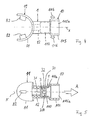
- Fig. 4
- the supervision of a further embodiment of a line element according to the invention
- Fig. 5
- 4 in longitudinal section
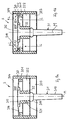
- Fig. 6
- a section through a further embodiment of a line element according to the invention
- Fig. 7a
- 6 with a nasal mask that can be fastened to the end on the patient side
- Fig. 7b
- 6 with a mouthpiece attachable to the patient end
- Fig. 8
- a further embodiment of a line element according to the invention
- Fig. 9a
- an enlarged view of a section through a one-way valve used in the line elements according to the invention in the closed position
- Fig. 9b
- the one-way valve according to FIG. 9a in the open position
- Fig. 10
- the supervision of the valve housing of the one-way valve according to FIG. 9a
- Fig. 11
- the section through the valve housing according to lines VV in Fig. 10th
- Fig. 12
- a side view of the valve body of the one-way valve according to FIG. 9a
- Fig. 13
- the bottom view of the valve body in a partially sectioned view along the section lines TT of FIG. 12th
- 14a-e
- in a schematic representation the assembly of the one-way valve according to FIG. 9.
Das in der Fig. 1 dargestellte Leitungselement 1 dient der
Atemgasversorgung eines Patienten und weist einen etwa
rechtwinklig abgewinkelt verlaufenden rohrförmigen Korpus 13
mit einem Lumen 12 auf, der ein als leitungsseitiges Ende 10
bezeichnetes Ende und ein als patientenseitiges Ende 11
bezeichnetes Ende aufweist. Das leitungsseitige Ende 10 und
das patientenseitige Ende 11 sind über das innerhalb des
rohrförmigen Korpus 13 durchgängig verlaufende Lumen 12
miteinander verbunden, wobei das Lumen 12 einen Atemgasweg
durch das Leitungselement vom leitungsseitigen Ende 10 zum
patientenseitigen Ende 11 bildet. Der Korpus 13 des
Leitungselementes 1 weist ferner im Bereich des Außenumfanges
des patientenseitigen Endes 11 einen auf diesen Außenumfang
aufgesteckten Kupplungsring 2 und ein vom patientenseitigen
Ende 11 her in das durchgehende Lumen 12 des Leitungselementes
1 eingestecktes Einwegeventil 3 auf, welches nachfolgend noch
näher erläutert wird.The
Wie bereits eingangs erläutert, dient das in der Fig. 1
dargestellte Leitungselement 1 der Atemgasversorgung eines
Patienten. Zu diesem Zweck wird eine hier nicht dargestellte
Atemgasleitung, beispielsweise ein Standardbeatmungsschlauch
nach DIN/ISO 5356/1 mit dem leitungsseitigen Ende 10 des
Leitungselementes 1 verbunden, beispielsweise auf den das
durchgehende Lumen 12 umgebenden Korpus 13 vom
leitungsseitigen Ende 10 her aufgesteckt, wozu der Korpus 13
in diesem Bereich leicht konisch ausgebildet ist. An dem dem
leitungsseitigen Ende 10 abgewandten patientenseitigen Ende 11
des Leitungselementes 1 wird ein Mundstück oder eine Maske
beispielsweise die in der Fig. 1 dargestellte Nasenmaske 4
durch Aufstecken gemäß Pfeil P3 angeschlossen, so daß ein
durchgehender Atemgasweg über das durchgehende Lumen 12 des
Leitungselementes 1 bis in den Innenraum 40 der Nasenmaske 4,
ausgehend von einer am leitungsseitigen Ende 10 des
Leitungselementes 1 angeschlossenen Atemgasleitung, zur
Atemgasversorgung eines Patienten ausgebildet ist. Die
Befestigung der Nasenmaske 4 am patientenseitigen Ende 11 des
Leitungselementes 1 erfolgt mittels des auf den Korpus 13 im
Bereich des patientenseitigen Endes 11 aufgesteckten
Kupplungsringes 2, der entlang seines Außenumfanges eine
umlaufende Nut 22 aufweist, in die ein auf der Innenseite des
Anschlußbereiches 4a der Nasenmaske 4 ausgebildeter
Befestigungsbereich 42 einsetzbar ist, wenn die Nasenmaske 4
gemäß Pfeil P3 auf den am patientenseitigen Ende 11 des Korpus
13 angebrachten Kupplungsring 2 aufgesetzt wird.As already explained at the beginning, this is used in FIG. 1
shown
Um bei der hierdurch ermöglichten Atemgasversorgung eines
Patienten den Atemgasstrom durch das Leitungselement 1
zwangsweise in nur einer gewünschten Richtung - hier der
Einatemrichtung E des Patienten - zu ermöglichen, ist das
Einwegeventil 3 in den vom durchgehenden Lumen 12 des
Leitungselementes 1 gebildeten Atemgasweg vom
patientenseitigen Ende 11 her eingesetzt. Das Einwegeventil
gibt auf Grund seiner konstruktiven Gestaltung lediglich in
einer Richtung den Atemgasweg frei und verschließt diesen in
entgegengesetzter Richtung, so daß mittels entsprechend
orientiertem Einsetzen des Einwegeventils 3 in das
durchgehende Lumen 12 die gewünschte zwangsweise Steuerung der
Atemgasrichtung durch das Leitungselement 1 bewirkbar ist. In
dem in der Fig. 1 dargestellten Ausführungsbeispiel ist das
Einwegeventil 3 so in den vom Lumen 12 gebildeten Atemgasweg
eingesetzt, daß gemäß Pfeilen E vom leitungsseitigen Ende 10
her Atemgas über die hier angeschlossene Atemgasleitung und
das durchgehende Lumen 12 in Einatemrichtung des Patienten in
die Nasenmaske 4 gelangen und dort vom Patienten eingeatmet
werden kann. In entgegengesetzter Richtung, d.h. der
Ausatemrichtung des Patienten, verschließt jedoch das
Einwegeventil 3 den vom Lumen 12 ausgebildeten Atemgasweg, so
daß in der entgegen Pfeil E gerichteten Richtung kein Atemgas
in die Atemgasleitung am leitungsseitigen Ende 10 gelangen
kann und eine problemlose Atemgasversorgung des Patienten
gewährleistet ist.In order for the breathing gas supply thereby made possible
Patient the breathing gas flow through the
Wie insbesondere der Fig. 3 entnehmbar ist, ist das
Einwegeventil 3 in der gewünschten Orientierung zur Freigabe
bzw. zum Verschließen einer bestimmten Atemgasrichtung, hier
zur Freigabe in Einatemrichtung des Patienten gemäß Pfeil E in
das durchgehende Lumen 12 des Leitungselementes 1 gemäß
Pfeilen P2 vom Patientenseitigen Ende 11 des Korpus 13 her
eingesteckt. Zu diesem Zweck weist der das durchgehende Lumen
12 umgebende Korpus 13 zum patientenseitigen Ende 11 hin eine
stufenförmige Erweiterung 110 auf, die als Aufnahmeraum für
das Einwegeventil 3 dient, so daß dieses gemäß den Pfeilen P2
vom patientenseitigen Ende 11 her in das Leitungselement 1
einsteckbar ist. Um eine sichere Verankerung des in den
stufenförmig erweiterten Aufnahmeraum 110 eingesteckten
Einwegeventiles 3 zu ermöglichen, kann dieser Aufnahmeraum 110
und die Außenwandung des Ventilgehäuses 30 des Einwegeventiles
3 leicht konisch ausgebildet sein, so daß beim Einstecken des
Einwegeventiles 3 in den Aufnahmeraum 110 eine Selbsthemmung
zwischen diesen erzeugt wird.As can be seen in particular from FIG. 3, this is
One-
In den Fig. 9a bis 13 ist ein bevorzugter Aufbau eines
Einwegeventiles 3 dargestellt. Das Einwegeventil 3 umfaßt ein
rohrförmiges Ventilgehäuse 30 mit einem im Inneren
ausgebildeten Ventilraum 305 und einen in das Ventilgehäuse 30
eingesetzten pilzförmigen Ventilkörper 31 mit Ventilschaft 310
und Ventilschirm 314. In dem Ventilgehäuse 30 ist, wie sich
auch aus den Darstellungen gemäß Fig. 10 und 11 ergibt, eine
Buchse 32 mit Wandung 320 und mit einer darin ausgebildeten
Durchgangsbohrung 321 ausgebildet, die innerhalb des
Ventilraumes 305 koaxial zum Ventilgehäuse 30 gehaltert ist.
Hierzu sind, siehe insbesondere Fig. 10, mehrere, hier
insgesamt drei sich radial zwischen der Buchse 32 und der
Wandung 300 des Ventilgehäuses 30 erstreckende Haltestege 322
vorgesehen, die die Buchse 32 in gewünschten koaxialen
Ausrichtung innerhalb des Ventilgehäuses 30 halten.
Gleichzeitig ist zwischen den radial den Ventilraum 305
durchsetzenden Haltestegen 322 ein ausreichend großer Freiraum
für einen Atemgasdurchgang durch das Einwegeventil 3 gegeben.9a to 13 is a preferred structure of a
One-
Ferner ist in dem Ventilgehäuse 30 eine ringförmige
Anlagefläche 302 von einem umlaufenden und von der Innenwand
des Ventilgehäuses 30 vorkragenden Auflagesteg 301
ausgebildet. Das Ventilgehäuse 30 mit Auflagesteg 301, Buchse
32 und Haltestegen 322 ist bevorzugt einstückig aus einem
thermoplastischen und/oder elastomeren Kunststoff, wie einem
Polycarbonat oder Polysulfon, zum Beispiel nach dem
Spritzgußverfahren hergestellt.Furthermore, an annular one is in the
Das Einwegeventil 3 gemäß Figuren 9a, 9b ist
rotationssymmetrisch aufgebaut, d.h. die Mittelachse M ist
zugleich die Mittelachse des Ventilkörpers 31, der Buchse 32
und des Ventilgehäuses 30 und stellt auch die Längsachse des
Einwegeventiles 3 dar. The one-
Der pilzförmige Ventilkörper 31, der in näheren Einzelheiten
in den Fig. 12 und 13 dargestellt ist, umfaßt einen
Ventilschaft 310 mit einem einseitig an den Ventilschaft 310
angeformten und sich quer zur Mittelachse M des Ventilschaftes
310 erstreckenden Ventilschirm 314, so daß der Ventilkörper 31
einen etwa T-förmigen Querschnitt aufweist. Der Ventilschirm
314 ist an seinen äußeren Randbereichen 315 bevorzugt
möglichst dünnwandig ausgebildet, ist jedoch im
Übergangsbereich 312 zum hieran angeformten Ventilschaft 310
verstärkt ausgebildet. Zu diesem Zweck ist der
Übergangsbereich 312 zum einen verdickt ausgebildet. Ferner
erstrecken sich beidseits des Ventilschaftes 310 zwei
angeformten Stützstege 313 radial nach außen, die mit dem
Übergangsbereich 312 und dem Ventilschirm 314 verbunden sind.
In der Darstellung gemäß Fig. 12 ist ersichtlich, daß der
Ventilschirm von der Mittelachse M ausgehend zu seinen äußeren
Randbereichen 315 leicht abwärts geneigt verlaufend, d.h. in
Richtung auf das freie Ende 310a des Ventilschaftes 310
verlaufend, ausgebildet ist. Durch die Anordnung der
Stützstege 313 auf der dem Ventilschaft 310 zugewandten Seite
des Ventilschirmes 314 wird der Ventilschirm 314 in Richtung
seines Außenumfanges ausgesteift und kann nur am Außenumfang
definierte elastische Bewegungen ausführen.The mushroom-shaped
Zur Ausbildung des in den Fig. 9a, 9b dargestellten
Einwegeventiles 3 wird der vorangehend erläuterte Ventilkörper
31 mit seinem Ventilschaft 310 in die Durchgangsbohrung 321
der Buchse 32 innerhalb des Ventilgehäuses 30 eingesteckt. In
der in der Fig. 9a, 9b dargestellten Einbauposition ist der
Ventilkörper 31 hierbei ortsfest innerhalb der Buchse 32 des
Ventilgehäuses 30 gehaltert. Zu diesem Zweck weist der
Ventilschaft 310 des Ventilkörpers 31 eine Verdickung 311 auf,
die vom Ventilschirm 314 in einem der Länge der Buchse 32
entsprechenden Abstand auf dem Ventilschaft 310 angeordnet
ist. Wenn der Ventilkörper 31 in der in den Fig. 9a, 9b
dargestellten Endstellung innerhalb der Buchse 32 eingesteckt
ist, wird somit eine ortsfeste Verbindung des Ventilkörpers 31
mit der Buchse 32 und damit des Ventilgehäuses 30 geschaffen,
wobei der Übergangsbereich 312 des Ventilkörpers 31 an dem
einen stirnseitigen Ende der Buchse 32 und die Verdickung 311
an dem anderen stirnseitigen Endbereich der Buchse 32 anliegt
und eine weitere Bewegung des Ventilkörpers 31 entlang seiner
Mittelachse M nicht mehr möglich ist. Hierbei liegt der
Ventilschirm 312 mit seinen in der Fig. 12 mit Bezugsziffer
315 gekennzeichneten Randbereichen auf dem umlaufenden
ringförmigen Auflagesteg 301 des Ventilgehäuses 30 abdichtend
auf. Die hier ausgebildete Dichtfläche verläuft damit
ringförmig umlaufend innerhalb des Ventilgehäuses 30 und ist
senkrecht zur Mittelachse M angeordnet.To form the shown in FIGS. 9a, 9b
One-
Das Einstecken des Ventilkörpers 31 in die innerhalb des
Ventilgehäuses 30 gelagerte Buchse 32 bis hin zur in den Fig.
9a, 9b dargestellten Einbauposition ist in den Fig. 14a bis
14e in mehreren Schritten dargestellt.Inserting the
In einem ersten in der Fig. 14a dargestellten Schritt wird das
freie Ende 310a des Ventilschaftes 310 des Ventilkörpers 31 in
die im Inneren der Buchse 32 ausgebildete Durchgangsbohrung
321 eingeführt und gemäß Pfeil P1 der Ventilkörper 31 durch
die Buchse 32 vorgeschoben, bis die Verdickung 311 oberseitig
an dem stirnseitigen Ende der Buchse 32 anliegt. Das Einführen
des Ventilschaftes 310 in die Buchse 32 wird hierbei durch
eine leicht konische Ausbildung des Ventilschaftes 310 zu
seinem freien Ende 310a unterstützt. Bei weiterem Vorschieben
in Pfeilrichtung P1 wird je nach Elastizitätsverhältnissen der
verwendeten Materialien für die Buchse 32 und den Ventilkörper
31 entweder der Ventilkörper 31 unter elastischer Aufweitung
der Buchse 32 aufgrund der steiferen Verdickung 311 durch die
Buchse 32 hindurchgetrieben oder es erfolgt eine elastische
Kompression der Verdickung 311 des Ventilkörpers 31 durch eine
demgegenüber steifere Buchse 32, wodurch durch ebenfalls ein
weiteres Vorschieben des Ventilkörpers in Pfeilrichtung P1
ermöglicht ist. Bevorzugt ist jedoch der Ventilkörper 31
einstückig aus einem weichen, elastischen Material, z.B.
Silikon hergestellt und die Buchse 32 aus einem demgegenüber
härter und steifer eingestellten Material gefertigt.In a first step shown in FIG
Bei weiterem Vorschieben des Ventilkörpers 31 durch die Buchse
32 taucht, wie in Fig. 14c dargestellt, der Ventilschirm 314
in den vom Ventilgehäuse 30 umgebenden Ventilraum 305 ein und
wird, siehe Fig. 14b, an den umlaufenden Anlagesteg 301 des
Ventilgehäuses 30 herangeführt. In der in der Fig. 14e
dargestellten Endstellung, die auch der Darstellung gemäß Fig.
9a entspricht, liegt der Ventilschirm 314 auf dem nach innen
vorkragenden Anlagesteg 301 des Ventilgehäuses 30 auf und der
Ventilkörper 31 ist in der Buchse 32 mit seinem
Übergangsbereich 312 und der Verdickung 311 in der vorangehend
bereits erläuterten Weise festgeklemmt.As
In dieser in der Fig. 9a dargestellten Position ist durch die
Auflage des Ventilschirmes 314 auf dem Auflagesteg 301 eine
Abdichtung gegeben, so daß der Atemgasdurchgangsweg über den
Ventilraum 305 innerhalb des Ventilgehäuses 30 verschlossen
ist.In this position shown in Fig. 9a is by
Support of the
Um jedoch in einer gewünschten Richtung ein Öffnen des
Einwegeventiles 3 zu ermöglichen, ist der Ventilschirm 314 aus
einem elastischen Material, beispielsweise Silikon,
hergestellt und im Bereich seines Außenumfanges, mit dem er
auch auf dem Anlagesteg 301 aufliegt, möglichst dünnwandig
ausgebildet.However, in order to open the
To enable one-
Sofern, wie in der Fig. 9b dargestellt, Atemgas gemäß Pfeilen
L über die als Gaseintrittsöffnung 303 bezeichnete Öffnung in
den Ventilraum 305 eintritt, wirkt auf den Ventilschirm 314
gegenüber der als Gasaustrittsöffnung 304 bezeichneten Seite
ein als Vordruck bezeichneter Überdruck ein. Bereits bei einem
äußerst geringen Vordruck von beispielsweise 0,01 bis 0,02 bar
heben auf Grund dieser Druckverhältnisse die Randbereiche des
Ventilschirmes 314 gemäß Pfeilen P2 elastisch vom Auflagesteg
301 des Ventilgehäuses 30 ab, so daß die zuvor ringförmig
umlaufende geschlossene Dichtfläche aufgehoben wird und das
Atemgas gemäß den Pfeilen L in Fig. 9b um den Außenumfang des
Ventilschirmes 314 herum von der Gaseintrittsöffnung 303 zur
Gasaustrittsöffnung 304 strömen und dort das Ventilgehäuse 30
wieder verlassen kann. In dieser auch als Freigaberichtung
gemäß Pfeilen L bezeichneten Richtung ist von daher auf Grund
des bereits für ein Öffnen des Ventiles ausreichenden äußerst
geringen Vordruckes ein nahezu ungehinderter Gasdurchgang
durch das Einwegeventil 3 ermöglicht.If, as shown in Fig. 9b, breathing gas according to arrows
L via the opening in FIG
the
Hingegen erfolgt in umgekehrter, auch als Sperrichtung
bezeichneter Richtung, d.h. entgegen Pfeilen L in Fig. 9b, ein
sofortiges Anlegen des Ventilschirmes 314 auf dem Anlagesteg
301 des Ventilgehäuses, so daß von der Gasaustrittsöffnung 304
zur Gaseintrittsöffnung 303 entgegen Pfeilen L kein Atemgas
durch das Einwegeventil 3 strömen kann. Diese Sperrwirkung des
Einwegeventiles 3 entgegen Pfeil L kann auch durch sehr hohen
Atemgasdruck nicht überwunden werden, da dieser lediglich zu
einer noch festeren Auflage des Ventilschirmes 314 auf dem
Auflagesteg 301 führt, so daß die Dichtwirkung selbsttätig mit
dem anliegenden Druck erhöht wird. Bei sehr hohem Druck in
Sperrichtung verhindern überdies die Haltestege 322 für die
Buchse 32 ein Durchdrücken des Dichtschirmes 314 und damit
einen Verlust der Dichtwirkung. Je nach Anforderung können
hierzu auich mehr als die dargestellten drei Haltestege 322
vorgesehen sein.On the other hand, it takes place in reverse, also as the blocking direction
designated direction, i.e. contrary to arrows L in Fig. 9b
immediate application of the
Um auch bei längerem Gebrauch und beispielsweise erhöhter
Adhäsion, die sich durch Niederschlag von Feuchtigkeit auf den
Ventilschirm 314 aus dem Atemgas ausbilden kann, ein stets
leichtes und zuverlässiges Öffnen des Einwegeventiles 3 in der
Freigaberichtung zu ermöglichen, ist der Auflagesteg 301 auf
seiner der dem Ventilschirm zugewandten Seite kuppenförmig mit
einem Radius von z.B. 0,4 mm ausgebildet, wodurch sich eine
annähernd linienförmige Anlagefläche 302 im Scheitelbereich
für die dichtende Anlage des Ventilschirmes 314 ergibt. Durch
diese linienförmige Anlagefläche wird jedoch die der Öffnung
des Ventilschirmes 314 unerwünscht entgegenwirkende Adhäsion
zwischen Anlagesteg 301 und Ventilschirm 314 auf ein Minimum
begrenzt.To also with longer use and for example increased
Adhesion, which is caused by precipitation of moisture on the
Can
Auch der Ventilkörper 31 ist bevorzugt einstückig nach dem
Spritzgußverfahren hergestellt, zum Beispiel aus dem bereits
erwähnten weichelastischen Kunststoff auf Basis von Silikon.The
Sowohl bei der in der Fig. 9a gezeigten abdichtenden Anlage
des Ventilschirmes 314 auf dem Anlagesteg 301 des
Ventilgehäuses 30 als auch bei dem in der Fig. 9b
dargestellten geöffneten Ventilschirm 314 zur Ausbildung eines
Atemgasdurchgangsweges durch das Einwegeventil 3 befindet sich
der dünnwandige Ventilschirm 314 stets innerhalb des
Ventilraumes 305 und ist von der Wandung 300 des
Ventilgehäuses 30 umgeben, so daß der empfindliche
Ventilschirm 314 im Ventilraum 305 vor Beschädigungen oder
Berührung gut geschützt ist.Both in the sealing system shown in FIG. 9a
of the
Mit dem vorangehend erläuterten Einwegeventil 3 ist es somit
möglich, bei Einsatz in einem Leitungselement, beispielsweise
dem in der Fig. 1 dargestellten Leitungselement 1, den mittels
des Lumens 12 ausgebildeten Atemgasweg lediglich in der
gewünschten Richtung durch das Leitungselement 1 freizugeben
und in der entgegengesetzten Richtung zu verschließen, so daß
eine zuverlässige Atemgasversorgung des Patienten
gewährleistet ist. Hierzu ist es lediglich erforderlich, daß
Einwegeventil 3 in der gewünschten Orientierung in den
Aufnahmeraum 110 des Leitungselementes 1 einzusetzen. Bei den
in den Figuren dargestellten Ausführungsbeispielen weist
hierbei der Ventilschaft 310 des Ventilkörpers 31 mit seinem
freien Ende 310a stets entgegen der Freigaberichtung.With the one-
Zur Befestigung der beispielhaft in der Fig. 1 dargestellten
Nasenmaske 4 am patientenseitigen Ende 11 des
Leitungselementes 1 wird der bereits erwähnte Kupplungsring 2
verwendet, der, wie auch aus Fig. 2 ersichtlich ist, vom
patientenseitigen Ende 11 her auf den Korpus 13 des
Leitungselementes 1 gemäß Pfeilen P1 aufsteckbar ist. Dazu
weist das Leitungselement 1 in seinem an das patientenseitige
Ende 11 angrenzenden Bereich einen gegenüber dem rohrförmigen
Korpus 13 im Außenumfang vergrößerten Aufsteckbereich 11a auf,
der an seinem dem patientenseitigen Ende 11 abgewandten Ende
von einem vorstehenden umlaufenden Anschlag 111 und an dem dem
patientenseitigen Ende 11 zugewandten Ende von einer
umlaufenden Rastnase 112 begrenzt wird. Der Kupplungsring 2,
der einen dem Außendurchmesser des Aufsteckbereiches 11a
entsprechenden Ringkörper 20 aufweist, ist somit gemäß Pfeilen
P1 in Fig. 2 auf das Leitungselement 1 aufsteckbar, und zwar
so weit, bis dessen Kante 21a am Anschlag 111 anliegt. In
dieser Stellung hinterrastet die umlaufende Rastnase 112 an
der gegenüberliegenden Kante 21 des Kupplungsringes 2, so daß
dieser gegen ein erneutes Abnehmen vom Leitungselement 1
entgegen Pfeilrichtung P1 gesichert ist und mit dem Korpus 13
des Leitungselementes 1 verbunden wird.For fastening the example shown in FIG. 1
Nasal mask 4 at the
Die Befestigung des Kupplungsringes 2 für die Nasenmaske 4 am
Anschlußstück 1 durch Aufstecken und Verrasten in der
vorangehend beschriebenen Weise bewirkt darüber hinaus, daß
der Kupplungsring 2 zwar gegen ein Abziehen entgegen
Pfeilrichtung P1 in Fig. 2 gesichert ist, jedoch um die mit M1
in Fig. 1 gekennzeichnete Mittelachse des patientenseitigen
Endes 11 frei drehbar ist, so daß die am Kupplungsring 2
befestigte Nasenmaske 4 mitsamt des Kupplungsringes 2 relativ
zum Leitungselement 1 um die Achse M1 drehbar ist, was die
Handhabung wesentlich erleichtert. Um darüber hinaus ein
ungewolltes Entweichen von Atemgas zwischen dem Korpus 13 des
Leitungselementes 1 und dem Kupplungsring 2 zu verhindern, ist
der Korpus 13 im Aufsteckbereich 11a mit mehreren, hier drei
parallel zueinander verlaufenden Nuten 113 versehen, in die
hier nicht dargestellte Dichtungsringe zur Abdichtung des
Spaltes zwischen dem patientenseitigen Ende 11 des Korpus 13
des Leitungselementes 1 und dem Kupplungsring 2 eingesetzt
werden können.The attachment of the
Eine weitere vorteilhafte Ausführungsform des
Leitungselementes 1 ist in den Fig. 6, 7a, 7b dargestellt. Das
in in diesen Figuren dargestellte Leitungselement weist
wiederum einen Korpus 13 mit einem patientenseitigen Ende 11
auf, welches mit einem Kupplungsring 2 in der bereits
beschriebenen Weise versehen ist. Im Gegensatz zu dem in der
Fig. 1 dargestellten Ausführungsbeispiel weist jedoch der
Korpus 13 des Leitungselementes 1 gemäß Fig. 6, 7a, 7b
insgesamt zwei leitungsseitige Enden 10, 10a auf, die etwa
rechtwinklig zueinander angeordnet sind und über zwei Lumen
12, 12a nach Art eines T miteinander und mit dem
patientenseitigen Ende 11 kommunizieren. Hierbei verläuft das
Lumen 12 geradlinig durchgängig vom patientenseitigen Ende 11
zum leitungsseitigen Ende 10 des Korpus 13 und das zum
leitungsseitigen Ende 10a führende Lumen 12a mündet etwa im
mittleren Bereich des Lumens 12 rechtwinklig in dieses ein. In
jedes Lumen 12, 12a ist ein Einwegeventil 3 des bereits
beschriebenen Aufbaus eingeschoben, hier jedoch vom jeweiligen
leitungsseitigen Ende 10, 10a her in einen entsprechenden
stufenförmig erweiterten Aufnahmeraum 110 des Korpus 13
eingebracht. Beide leitungsseitigen Enden 10, 10a des Korpus
13 sind im wesentlichen gleich ausgebildet, so daß gleich
aufgebaute Einwegeventile 3 in die die Atemgaswege bildenden
Lumen 12, 12a eingesetzt werden können.Another advantageous embodiment of the
Auf Grund der Ausbildung des Leitungselementes 1 mit einem
patientenseitigen Ende 11, welches mit zwei leitungsseitigen
Enden 10, 10a über Lumen 12, 12a verbunden ist, weist das
Leitungselement 1 zwei Atemgaswege auf, die von den Lumen 12,
12a gebildet werden. An jedes leitungsseitige Ende 10, 10a
können Atemgasleitungen angeschlossen werden. Hierzu sind die
mit Bezugszeichen 5 bzw. 6 gekennzeichneten Anschlußkonen nach
DIN/ISO 5356/1 an den leitungsseitigen Enden 10, 10a
befestigt, beispielsweise mittels der dargestellten
einrastbaren und selbsthaftenden Nut- und Federverbindungen.
Die Anschlußkonen 5, 6 werden hierbei um ihre Mittelachse
drehbar am Leitungselement 1 im Bereich der leitungsseitigen
Enden 10, 10a befestigt. Auf diese Anschlußkonen 5, 6 sind
sodann in bekannter Weise entsprechende Atemgasschläuche
(nicht dargestellt) als Atemgasleitungen aufsteckbar. Due to the design of the
Es ist von daher möglich, beispielsweise über den
Anschlußkonus 6 am leitungsseitigen Ende 10a Atemgas zum
Einatmen durch den Patienten über das patientenseitige Ende 11
zuzuführen, was mit Pfeil E angedeutet ist. Ebenso kann vom
Patienten ausgeatmetes Atemgas vom patientenseitigen Ende 11
her über den Atemgasweg durch das Leitungselement 1 in eine
beispielsweise am leitungsseitigen Ende 10 auf den
Anschlußkonus 5 aufgesteckte Atemgasleitung gemäß Pfeil A
abgeleitet werden. Um bei dieser Aufteilung der Atemgaswege
stets die gewünschte zwangsweise Steuerung von eingeatmetem
Atemgas und ausgeatmetem Atemgas gemäß Pfeilen E, A zu
gewährleisten, sind die Einwegeventile 3, 3a in den Lumen 12,
12a in der entsprechenden Orientierung eingesetzt, so daß sie
eine zwangsweise Steuerung des Atemgasstromes durch das
Leitungselement 1 in der vorangehend geschilderten Weise
ermöglichen. Das Einwegeventil 3a im Lumen 12a des
leitungsseitigen Endes 10a öffnet lediglich in Einatemrichtung
des Patienten gemäß Pfeil E, so daß über das leitungsseitige
Ende 10a von der dort angeschlossenen Atemgasleitung
zugeführtes Atemgas über das Lumen 12a und einen Teilabschnitt
des Lumens 12 zum patientenseitigen Ende 11 strömt und vom
Patienten eingeatmet werden kann. In entgegengesetzter
Richtung verschließt jedoch das Einwegeventil 3a den
Atemgasweg durch das Lumen 12a, so daß vom Patienten in
Ausatemrichtung gemäß Pfeil A ausgeatmetes Atemgas nicht in
die an das leitungsseitige Ende 10a angeschlossene
Atemgasleitung gelangen kann. In dieser Richtung öffnet jedoch
das in umgekehrter Orientierung zum Einwegeventil 3a in das
Lumen 12 am leitungsseitigen Ende 10 des Korpus 13 eingesetzte
Einwegeventil 3, so daß ausgeatmetes Atemgas vom
patientenseitigen Ende 11 gemäß Pfeil A durch das Lumen 12 und
das Einwegeventil 3 in die an das leitungsseitige Ende
angeschlossene Atemgasleitung abgeführt werden kann.It is therefore possible, for example via the
Connection cone 6 at the
Mit einem derart ausgebildeten Leitungselement 1 mit zwei
leitungsseitigen Enden 10, 10a zum Anschluß je einer
Atemgasleitung kann somit sowohl das Einatmen des Patienten
gemäß Pfeil E als auch das Ausatmen gemäß Pfeil A und die
dadurch bedingte Zu- bzw. Abführung des jeweiligen Atemgases
über das Leitungselement 1 und ein am patientenseitigen Ende
11 angeschlossenes Mundstück oder eine Maske für den Patienten
zwangsweise erfolgen.With a
Die vorangehend erläuterte Anordnung und Orientierung der
Einwegeventile 3, 3a ist lediglich beispielhaft zu verstehen,
es ist auch möglich, je nach Anwendungsfall die umgekehrte
Orientierung der Einwegeventile 3, 3a vorzusehen.The arrangement and orientation of the
One-
An das patientenseitige Ende 11 des Leitungselementes 1 ist
mittels des in Fig. 1 bereits erläuterten Kupplungsringes 2
sowohl eine in der Fig. 7a dargestellte Nasenmaske 4 wie auch
ein in der Fig. 7b beispielhaft dargestelltes Mundstück 8 für
den Patienten anschließbar. Beide sind hierzu mit entsprechend
angepaßten Befestigungsbereichen ausgebildet. Darüber hinaus
können am Kupplungsring 2 noch Halteösen 7 mit
Durchgangsöffnungen 70 vorgesehen sein, an denen Haltebänder
zur Fixierung des Leitungselementes 1 mitsamt des daran
befestigten Mundstückes 8 bzw. der Maske 4 am Kopf des
Patienten befestigbar sind.At the
Die vorangehend beschriebenen Leitungselemente 1 mit Korpus 13
und Kupplungsring 2 ist bevorzugt aus einem Hart-Kunststoff,
beispielsweise einem Polycarbonat oder Polysulfon, mit einer
Temperaturfestigkeit von mindestens 130°C, beispielsweise nach
dem Spritzgußverfahren hergestellt. Diese Materialauswahl
ermöglicht, ebenso wie auch beim bereits erläuterten
Einwegeventil die mehrfache Wiederverwendung des
Leitungselementes 1, da es mittels Dampf mehrfach
sterilisierbar ist.The
Eine Abwandlung des in der Fig. 7b dargestellten
Leitungselementes ist in der Fig. 8 dargestellt. Hierbei ist
am patientenseitigen Ende 11 ein Mundstück nicht als separates
auf einem Kupplungsring 2 zu befestigendes Teil ausgebildet,
sondern an das patientenseitige Ende 11 ist das Mundstück
integral angeformt. Auch in diesem Ausführungsbeispiel weist
das Leitungselement 1 neben dem als Mundstück ausgebildeten
patientenseitigen Ende 11 zwei leitungsseitige Enden 10, 10a
auf, die über Lumen 12, 12a, die die Atemgaswege bilden,
miteinander verbunden sind. In jedes Lumen 10, 10a ist ein
Einwegeventil 3, 3a zur zwangsweisen Steuerung des
Einatemgases gemäß Pfeil E und Ausatemgases gemäß Pfeil A
eingesetzt. Wiederum sind die Einwegeventil 3, 3a von den
leitungsseitigen Enden 10, 10a des Korpus 13 her in
entsprechend zum leitungsseitigen Ende hin stufenförmig
erweiterte Aufnahmeräume 110 in dem Lumen 12, 12a eingesetzt,
wobei die Einwegeventile 3, 3a mittels in den Aufnahmeraum 110
vorstehende Haltewulste 110a in ihrer eingesteckten Position
gehalten werden. Die Haltewulste 110a unterteilen den
Aufnahmeraum 110, wobei ein Herausfallen des zwischen dem
stufenförmigen Absatz und den Haltewulsten 110a im inneren
Abteil des Aufnahmeraumes 110 gehalterten Einwegeventils 3
verhindert wird. Ferner sind die leitungsseitigen Enden 10,
10a mit Aufnahmebereichen 115 und entsprechend ausgebildeten
Aufnahmebohrungen 115a für den Anschluß genormter
Anschlußkonen nach DIN/ISO 5356/1 ausgebildet.A modification of that shown in Fig. 7b
Line element is shown in FIG. 8. Here is
at the
Es ist auch möglich, an Stelle des in der Fig. 8 dargestellten
Leitungselementes 1 mit einem patientenseitigen Ende 11 mit
angeformtem Mundstück und zwei leitungsseitigen Enden 10, 10a
ein Leitungselement gemäß den Fig. 4 und 5 vorzusehen, welches
ähnlich wie das Leitungselement gemäß Fig. 1 über nur ein
patientenseitiges Ende 11 und ein leitungsseitiges Ende 10 zum
Anschluß einer Atemgasleitung verfügt, die über ein
durchgehendes Lumen 12 im geradlinig verlaufenden Korpus 13
miteinander verbunden sind. In diesem Fall ist wiederum der
Korpus 13 am patientenseitigen Ende 11 mit einem integral
angeformten Mundstück ausgebildet, welches von einem
Lippenring 81 und nach innen vorstehenden Beißblöcken 82
gebildet ist, wie es auch bei dem in Fig. 8 dargestellten
Leitungselement 1 der Fall ist. In den zum leitungsseitigen
Ende 10 hin stufenförmig erweiterten Aufnahmeraum 110 des
Lumens 12 ist wiederum ein Einwegeventil 3 eingesetzt, welches
lediglich ein Ausatmen des Patienten vom patientenseitigen
Ende 11 zum leitungsseitigen Ende 10 in eine hieran
anschließbare Atemgasleitung ermöglicht, in der
entgegengesetzten Richtung jedoch ein Einatmen durch Schließen
und Abdichten verhindert. Hierdurch kann beispielsweise eine
exakte Analyse des ausgeatmenten Atemgases über ein an die
Atemgasleitung angeschlossenes Atemgasanalysegerät vorgenommen
werden. Das leitungsseitige Ende 10 ist wiederum für den
Anschluß eines genormten Konnektors nach DIN/ISO 5356/1
vorgesehen. Zur Fixierung des Leitungselementes 1 am Patienten
sind überdies am leitungsseitigen Ende 10 des Korpus 13
außenseitig vorstehende Befestigungszapfen 116 für die
Befestigung eines hier nicht dargestellten Befestigungsbandes
vorgesehen, welches beispielsweise um den Kopf des Patienten
gelegt werden kann.It is also possible to replace the one shown in FIG. 8
Claims (21)
dadurch gekennzeichnet, daß das Einwegeventil von einem rohrförmigen Ventilgehäuse (30) und einem in das Ventilgehäuse (30) eingesetzten pilzförmigen Ventilkörper (31) mit Ventilschaft (310) und Ventilschirm (314) gebildet ist, wobei in dem Ventilgehäuse (30) eine ringförmige Anlagefläche (302) von einem umlaufenden und von der Innenwand des Ventilgehäuses (30) vorkragenden Auflagesteg (301) sowie eine koaxial in dem Ventilgehäuse (30) angeordnete Buchse (32) ausgebildet ist und der Ventilschaft des Ventilkörpers (31) in der Buchse (32) gehaltert ist und der Ventilschirm (314) des Ventilkörpers (31) an der Anlagefläche (302) dichtend anliegt und bei einem Vordruck von mindestens 0,005 bis 0,02 bar in Freigaberichtung elastisch von der Anlagefläche (302) abhebt. Pipe element according to claim 1,
characterized in that the one-way valve is formed by a tubular valve housing (30) and a mushroom-shaped valve body (31) with valve stem (310) and valve shield (314) inserted into the valve housing (30), an annular contact surface in the valve housing (30) (302) is formed by a peripheral support web (301) projecting from the inner wall of the valve housing (30) and a bushing (32) arranged coaxially in the valve housing (30) and the valve stem of the valve body (31) in the bushing (32) is held and the valve screen (314) of the valve body (31) bears sealingly against the contact surface (302) and, at a pre-pressure of at least 0.005 to 0.02 bar, lifts elastically from the contact surface (302) in the release direction.
dadurch gekennzeichnet, daß der Ventilschaft (310) des Ventilkörpers (31) eine Verdickung (311) aufweist, die vom Ventilschirm (314) in einem der Länge der Buchse (32) entsprechenden Abstand auf dem Ventilschaft (310) angeordnet ist, so daß der Ventilschaft (310) in der Buchse (32) ortsfest zwischen dem Ventilschirm (314) und der Verdickung (311) gehaltert ist.Pipe element according to claim 2,
characterized in that the valve stem (310) of the valve body (31) has a thickening (311) which is arranged on the valve stem (310) at a distance corresponding to the length of the bushing (32) from the valve shield (314), so that the Valve stem (310) in the socket (32) is fixed between the valve shield (314) and the thickening (311).
dadurch gekennzeichnet, daß zur Erhöhung der Elastizität der Ventilschirm (314) dünnwandig ausgebildet und im Übergangsbereich (312) zum Ventilschaft (310) ausgesteift ist.Pipe element according to claim 2 or 3,
characterized in that to increase the elasticity the valve screen (314) is thin-walled and stiffened in the transition region (312) to the valve stem (310).
dadurch gekennzeichnet, daß der Ventilschaft (310) des Ventilkörpers (31) auf der der Freigaberichtung abgewandten Seite des Ventilschirmes (314) angeformt ist.Pipe element according to one of claims 2 to 4,
characterized in that the valve stem (310) of the valve body (31) is formed on the side of the valve screen (314) facing away from the release direction.
dadurch gekennzeichnet, daß der Auflagesteg (301) kuppenförmig zur Ausbildung einer annähernd linienförmigen Anlagefläche (302) im Scheitelbereich ausgebildet ist.Pipe element according to one of claims 2 to 5,
characterized in that the support web (301) is dome-shaped to form an approximately linear contact surface (302) in the apex area.
dadurch gekennzeichnet, daß das Einwegeventil aus bis mindestens 130°C temperaturbeständigen Materialien hergestellt ist, wobei der Ventilkörper (31) aus einem thermoplastischen und/oder elastomeren Kunststoff, wie Silikon, und das Ventilgehäuse (30) aus einem demgegenüber härter eingestellten Kunststoff, wie Polycarbonat oder Polysulfon, hergestellt ist. Pipe element according to one of claims 1 to 6,
characterized in that the one-way valve is made of materials that are temperature-resistant up to at least 130 ° C, the valve body (31) made of a thermoplastic and / or elastomeric plastic, such as silicone, and the valve housing (30) made of a plastic material, such as polycarbonate, which is set harder or polysulfone.
dadurch gekennzeichnet, daß das Ventilgehäuse des Einwegeventils außenseitig leicht konisch ausgebildet ist.Pipe element according to one of claims 1 to 7,
characterized in that the valve housing of the one-way valve is slightly conical on the outside.
dadurch gekennzeichnet, daß das patientenseitige Ende (11) mit einem Mundstück (8) oder einer Maske (4) für den Patienten ausgerüstet ist.Pipe element according to one of claims 1 to 8,
characterized in that the patient end (11) is equipped with a mouthpiece (8) or a mask (4) for the patient.
dadurch gekennzeichnet, daß das Mundstück oder die Maske integral am patientenseitigen Ende (11) angeformt ist.Pipe element according to claim 9,
characterized in that the mouthpiece or mask is integrally formed on the patient end (11).
dadurch gekennzeichnet, daß das patientenseitige Ende (11) mit einem Lippenring (81) als Mundstück ausgebildet ist.Pipe element according to one of claims 9 or 10,
characterized in that the patient end (11) is formed with a lip ring (81) as a mouthpiece.
dadurch gekennzeichnet, daß an den Lippenring (81) nach innen vorstehende Beißblöcke (82) angeformt sind.Pipe element according to claim 11,
characterized in that bite blocks (82) projecting inwards are molded onto the lip ring (81).
dadurch gekennzeichnet, daß der Korpus (13) am patientenseitigen Ende (11) außenseitig mit einem Kupplungsring (2) ausgerüstet ist, der um seine Mittelachse drehbar ist und der Kupplungsring entlang seines Außenumfanges eine umlaufende Nut (22) für die Befestigung eines entsprechend ausgebildeten Mundstückes oder einer Maske (4) aufweist. Pipe element according to one of claims 9 to 12,
characterized in that the body (13) on the patient end (11) is equipped on the outside with a coupling ring (2) which is rotatable about its central axis and the coupling ring has a circumferential groove (22) along its outer circumference for fastening a correspondingly designed mouthpiece or a mask (4).
dadurch gekennzeichnet, daß der Korpus (13) am patientenseitigen Ende (11) außenseitig mindestens eine umlaufende Nut (113) zur Aufnahme eines Dichtungsringes für die Abdichtung des patientenseitigen Endes (11) des Korpus (13) gegenüber dem Kupplungsring (2) aufweist.Pipe element according to claim 13,
characterized in that the body (13) has at the patient end (11) on the outside at least one circumferential groove (113) for receiving a sealing ring for sealing the patient end (11) of the body (13) with respect to the coupling ring (2).
dadurch gekennzeichnet, daß im Bereich des Außenumfanges eines leitungsseitigen Endes (10, 10a) des Korpus (13) mindestens ein Befestigungszapfen (116) für die Befestigung eines Haltebandes ausgebildet ist.Pipe element according to one of claims 1 to 14,
characterized in that in the area of the outer circumference of a line-side end (10, 10a) of the body (13) at least one fastening pin (116) is formed for fastening a retaining band.
dadurch gekennzeichnet, daß das mindestens eine Lumen im Korpus (13) zum leitungsseitigen Ende hin stufenförmig unter Ausbildung eines Aufnahmeraumes (110) erweitert ist, in welchen das Einwegeventil eingesetzt ist.Pipe element according to one of claims 1 to 15,
characterized in that the at least one lumen in the body (13) is widened step-wise towards the line end to form a receiving space (110) in which the one-way valve is inserted.
dadurch gekennzeichnet, daß das Lumen zum patientenseitigen Ende (11) hin stufenförmig unter Ausbildung eines Aufnahmeraumes (110) erweitert ist, in welchen das Einwegeventil eingesetzt ist.Pipe element according to one of claims 1 to 15,
characterized in that the lumen is widened step-wise towards the patient end (11) to form a receiving space (110) in which the one-way valve is inserted.
dadurch gekennzeichnet, daß der stufenförmig erweiterte Aufnahmeraum (110) durch einen in den Aufnahmeraum (110) hineinragenden Haltewulst (110a) abgeteilt ist,wobei das Einwegeventil in das innere Abteil des Aufnahmeraumes (110) ortsfest eingesetzt ist. Pipe element according to one of claims 16 or 17,
characterized in that the step-widened receiving space (110) is divided by a retaining bead (110a) projecting into the receiving space (110), the one-way valve being fixed in place in the inner compartment of the receiving space (110).
dadurch gekennzeichnet, daß es zwei leitungsseitige Enden (10,10a) und ein patientenseitiges Ende (11) aufweist, die über die Atemgaswege bildende Lumen (12, 12a) miteinander verbunden sind und in jedem Lumen (12, 12a) im Bereich des leitungsseitigen Endes (10, 10a) ein Einwegeventil (3, 3a) angeordnet ist, dergestalt, daß ein Einwegeventil (3) den Atemgasweg in der einen Richtung, ausgehend vom patientenseitigen Ende (11), und das andere Einwegeventil (3a) den Atemgasweg in der entgegengesetzten Richtung zum patientenseitigen Ende (11) freigibt und die Einwegeventile (3, 3a) in der jeweils entgegengesetzten Richtung den Atemgasweg verschließen, so daß der Atemgasweg zum Einatmen bzw. Ausatmen des Patienten wechselweise über das eine Einwegeventil (3a) bzw. das andere Einwegeventil (3) freigebbar ist.Pipe element according to one of claims 1 to 18,
characterized in that it has two line-side ends (10, 10a) and a patient-side end (11) which are connected to one another via the lumens (12, 12a) forming the respiratory gas paths and in each lumen (12, 12a) in the region of the line-side end (10, 10a) a one-way valve (3, 3a) is arranged such that a one-way valve (3) the breathing gas path in one direction, starting from the patient end (11), and the other one-way valve (3a) the breathing gas path in the opposite Releases direction to the patient end (11) and the one-way valves (3, 3a) close the respiratory gas path in the opposite direction, so that the respiratory gas path for inhaling or exhaling the patient alternately via one one-way valve (3a) or the other one-way valve ( 3) can be released.
dadurch gekennzeichnet, daß das mindestens eine leitungsseitige Ende für den Anschluß von genormten Konnektoren einer Atemgasleitung nach DIN/ISO 5365/1 ausgebildet ist.Pipe element according to one of claims 1 to 19,
characterized in that the at least one line-side end is designed for the connection of standardized connectors of a breathing gas line according to DIN / ISO 5365/1.
dadurch gekennzeichnet, daß der Korpus (13) abgewinkelt verlaufend ausgebildet ist.Pipe element according to one of claims 1 to 20,
characterized in that the body (13) is angled.
Applications Claiming Priority (4)
| Application Number | Priority Date | Filing Date | Title |
|---|---|---|---|
| DE29718137U DE29718137U1 (en) | 1997-10-16 | 1997-10-16 | Mouthpiece for a breathing gas line |
| DE29718137U | 1997-10-16 | ||
| DE29721766U | 1997-12-10 | ||
| DE29721766U DE29721766U1 (en) | 1997-12-10 | 1997-12-10 | Connector for a patient's breathing gas supply |
Publications (2)
| Publication Number | Publication Date |
|---|---|
| EP0911050A2 true EP0911050A2 (en) | 1999-04-28 |
| EP0911050A3 EP0911050A3 (en) | 1999-12-22 |
Family
ID=26060800
Family Applications (1)
| Application Number | Title | Priority Date | Filing Date |
|---|---|---|---|
| EP98119601A Withdrawn EP0911050A3 (en) | 1997-10-16 | 1998-10-16 | Conduit element for the connection of at least a breathing gas conduit to a patient |
Country Status (1)
| Country | Link |
|---|---|
| EP (1) | EP0911050A3 (en) |
Cited By (6)
| Publication number | Priority date | Publication date | Assignee | Title |
|---|---|---|---|---|
| WO2003082109A1 (en) * | 2002-03-28 | 2003-10-09 | Azienda Ospedaliera Pisana | Ventilation apparatus for pulmonary scintigraphy |
| EP1471964A1 (en) * | 2002-02-04 | 2004-11-03 | Fisher & Paykel Healthcare Limited | Breathing assistance apparatus |
| WO2006059161A3 (en) * | 2004-12-04 | 2006-09-08 | Concept 2 Manufacture Design L | Medical breathing apparatus |
| US9662467B2 (en) | 2000-10-19 | 2017-05-30 | Resmed R&D Germany Gmbh | Breathing mask for feeding a breathing gas to a mask user and discharge device for discharging breathing gas |
| US9757534B2 (en) | 2001-10-22 | 2017-09-12 | Resmed R&D Germany Gmbh | Breathing mask arrangement as well as an application device and a forehead support device for same |
| US10058671B2 (en) | 2001-10-22 | 2018-08-28 | Resmed R&D Germany Gmbh | Application device for a breathing mask arrangement |
Families Citing this family (1)
| Publication number | Priority date | Publication date | Assignee | Title |
|---|---|---|---|---|
| DE10201682A1 (en) | 2002-01-17 | 2003-07-31 | Map Medizin Technologie Gmbh | The breathing mask arrangement |
Family Cites Families (6)
| Publication number | Priority date | Publication date | Assignee | Title |
|---|---|---|---|---|
| US2936779A (en) * | 1956-10-11 | 1960-05-17 | Sierra Eng Co | Flapper valve |
| US3028873A (en) * | 1956-11-19 | 1962-04-10 | Sierra Eng Co | Non-rebreathing valve |
| GB8514849D0 (en) * | 1985-06-12 | 1985-07-17 | Vitalograph Ltd | Breathing aid |
| DE4037084A1 (en) * | 1990-11-22 | 1992-05-27 | Volker Bertram | OROPHARYNGEAL TUBE |
| IL104571A0 (en) * | 1993-02-01 | 1993-06-10 | Rabintex Ind Ltd | Mouth-to-mouth resuscitator |
| US5398673A (en) * | 1993-12-10 | 1995-03-21 | Environmental Support Systems, Inc. | Resuscitator-snorkel for land or water use |
-
1998
- 1998-10-16 EP EP98119601A patent/EP0911050A3/en not_active Withdrawn
Non-Patent Citations (1)
| Title |
|---|
| None |
Cited By (15)
| Publication number | Priority date | Publication date | Assignee | Title |
|---|---|---|---|---|
| US9662467B2 (en) | 2000-10-19 | 2017-05-30 | Resmed R&D Germany Gmbh | Breathing mask for feeding a breathing gas to a mask user and discharge device for discharging breathing gas |
| US10596342B2 (en) | 2000-10-19 | 2020-03-24 | Resmed R&D Germany Gmbh | Breathing mask for feeding a breathing gas to a mask user and discharge device for discharging breathing gas |
| US10245403B2 (en) | 2001-10-22 | 2019-04-02 | RedMed R&D Germany GmbH | Breathing mask arrangement as well as an application device and a forehead support device for same |
| US10058671B2 (en) | 2001-10-22 | 2018-08-28 | Resmed R&D Germany Gmbh | Application device for a breathing mask arrangement |
| US9889266B2 (en) | 2001-10-22 | 2018-02-13 | Resmed R&D Germany Gmbh | Breathing mask arrangement as well as an application device and a forehead support device for same |
| US9757534B2 (en) | 2001-10-22 | 2017-09-12 | Resmed R&D Germany Gmbh | Breathing mask arrangement as well as an application device and a forehead support device for same |
| EP2082774A2 (en) * | 2002-02-04 | 2009-07-29 | Fisher & Paykel Healthcare Limited | Breathing Assistance Apparatus |
| EP2082774A3 (en) * | 2002-02-04 | 2014-09-17 | Fisher & Paykel Healthcare Limited | Breathing Assistance Apparatus |
| US9750905B2 (en) | 2002-02-04 | 2017-09-05 | Fisher & Paykel Healthcare Limited | Breathing assistance apparatus |
| EP1471964A4 (en) * | 2002-02-04 | 2011-03-02 | Fisher & Paykel Healthcare Ltd | Breathing assistance apparatus |
| US9913953B2 (en) | 2002-02-04 | 2018-03-13 | Fisher & Paykel Healthcare Limited | Breathing assistance apparatus |
| EP1471964A1 (en) * | 2002-02-04 | 2004-11-03 | Fisher & Paykel Healthcare Limited | Breathing assistance apparatus |
| WO2003082109A1 (en) * | 2002-03-28 | 2003-10-09 | Azienda Ospedaliera Pisana | Ventilation apparatus for pulmonary scintigraphy |
| US8448643B2 (en) | 2004-12-04 | 2013-05-28 | Concept 2 Manufacture Design Ltd | Medical breathing apparatus |
| WO2006059161A3 (en) * | 2004-12-04 | 2006-09-08 | Concept 2 Manufacture Design L | Medical breathing apparatus |
Also Published As
| Publication number | Publication date |
|---|---|
| EP0911050A3 (en) | 1999-12-22 |
Similar Documents
| Publication | Publication Date | Title |
|---|---|---|
| DE102005014650B3 (en) | Assembly, for instilling lung preparations into patients' lungs, comprises instillation catheter and connector for attachment to tracheal or endotracheal tube including valve with elastic proximal opening and distal nose section | |
| DE4200008C2 (en) | Tracheal tube unit | |
| EP0822842B1 (en) | Tracheostomy cannula | |
| EP2253351B1 (en) | Slit valve in combination with a pneumatic switching circuit of a ventilator device | |
| DE3819237A1 (en) | ENDOTRACHEAL TUBE | |
| WO2014060242A1 (en) | Speaking valve for tracheostomy cannula | |
| DE202006017217U1 (en) | Safety device for intravenous injection, comprises an injection valve that is made of silica gel and has a side wall embedded in a seat and a central part subdivided by slits into freely bendable flaps | |
| DE10046872B4 (en) | Breathing assistance apparatus | |
| DE10014178C2 (en) | Device for discharging breathing gas | |
| EP0911050A2 (en) | Conduit element for the connection of at least a breathing gas conduit to a patient | |
| WO2014187511A1 (en) | Breathing mask with emergency breathing valve | |
| WO2016097363A1 (en) | Housing of a heat and moisture exchanger and method for detaching a cover from a housing | |
| WO1986006970A3 (en) | Tracheotomy closure | |
| WO2018210956A1 (en) | Exhalation valve for a ventilator apparatus with noise-reducing flow resistance | |
| DE3720482C2 (en) | ||
| EP2428244B1 (en) | Breathing mask | |
| EP3858413B1 (en) | Curved connecting unit for connecting a patient side coupling unit to a medical apparatus | |
| DE202017003898U1 (en) | Ventilation filter for a tracheostoma | |
| DE3623367C2 (en) | ||
| EP3727538B1 (en) | Tracheostomy cannula having a phonation opening | |
| EP3787722A1 (en) | Tracheal respiratory device having a sealing | |
| DE19543169A1 (en) | Endo-tracheal cannula with outer cannula inside which is inner cannula | |
| DE102018005054A1 (en) | Respiratory mask with means for coupling the harness | |
| EP3551267B1 (en) | Heat and moisture exchanger | |
| EP3257544B1 (en) | Emergency breathing valve with membrane ring |
Legal Events
| Date | Code | Title | Description |
|---|---|---|---|
| PUAI | Public reference made under article 153(3) epc to a published international application that has entered the european phase |
Free format text: ORIGINAL CODE: 0009012 |
|
| AK | Designated contracting states |
Kind code of ref document: A2 Designated state(s): AT BE CH DE DK ES FR GB GR IE IT LI NL PT SE |
|
| AX | Request for extension of the european patent |
Free format text: AL;LT;LV;MK;RO;SI |
|
| PUAL | Search report despatched |
Free format text: ORIGINAL CODE: 0009013 |
|
| RIC1 | Information provided on ipc code assigned before grant |
Free format text: 6A 61M 16/08 A, 6A 61M 16/20 B |
|
| AK | Designated contracting states |
Kind code of ref document: A3 Designated state(s): AT BE CH CY DE DK ES FI FR GB GR IE IT LI LU MC NL PT SE |
|
| AX | Request for extension of the european patent |
Free format text: AL;LT;LV;MK;RO;SI |
|
| 17P | Request for examination filed |
Effective date: 20000620 |
|
| AKX | Designation fees paid |
Free format text: AT BE CH DE DK ES FR GB GR IE IT LI NL PT SE |
|
| 17Q | First examination report despatched |
Effective date: 20040120 |
|
| STAA | Information on the status of an ep patent application or granted ep patent |
Free format text: STATUS: THE APPLICATION IS DEEMED TO BE WITHDRAWN |
|
| 18D | Application deemed to be withdrawn |
Effective date: 20040730 |