EP0913255B1 - Thermal ink jet print head energy control apparatus and method - Google Patents
Thermal ink jet print head energy control apparatus and method Download PDFInfo
- Publication number
- EP0913255B1 EP0913255B1 EP98307724A EP98307724A EP0913255B1 EP 0913255 B1 EP0913255 B1 EP 0913255B1 EP 98307724 A EP98307724 A EP 98307724A EP 98307724 A EP98307724 A EP 98307724A EP 0913255 B1 EP0913255 B1 EP 0913255B1
- Authority
- EP
- European Patent Office
- Prior art keywords
- voltage
- firing
- resistors
- pulse
- input
- Prior art date
- Legal status (The legal status is an assumption and is not a legal conclusion. Google has not performed a legal analysis and makes no representation as to the accuracy of the status listed.)
- Expired - Lifetime
Links
Images


Classifications
-
- B—PERFORMING OPERATIONS; TRANSPORTING
- B41—PRINTING; LINING MACHINES; TYPEWRITERS; STAMPS
- B41J—TYPEWRITERS; SELECTIVE PRINTING MECHANISMS, i.e. MECHANISMS PRINTING OTHERWISE THAN FROM A FORME; CORRECTION OF TYPOGRAPHICAL ERRORS
- B41J2/00—Typewriters or selective printing mechanisms characterised by the printing or marking process for which they are designed
- B41J2/005—Typewriters or selective printing mechanisms characterised by the printing or marking process for which they are designed characterised by bringing liquid or particles selectively into contact with a printing material
- B41J2/01—Ink jet
- B41J2/015—Ink jet characterised by the jet generation process
- B41J2/04—Ink jet characterised by the jet generation process generating single droplets or particles on demand
- B41J2/045—Ink jet characterised by the jet generation process generating single droplets or particles on demand by pressure, e.g. electromechanical transducers
- B41J2/04501—Control methods or devices therefor, e.g. driver circuits, control circuits
- B41J2/04506—Control methods or devices therefor, e.g. driver circuits, control circuits aiming at correcting manufacturing tolerances
-
- B—PERFORMING OPERATIONS; TRANSPORTING
- B41—PRINTING; LINING MACHINES; TYPEWRITERS; STAMPS
- B41J—TYPEWRITERS; SELECTIVE PRINTING MECHANISMS, i.e. MECHANISMS PRINTING OTHERWISE THAN FROM A FORME; CORRECTION OF TYPOGRAPHICAL ERRORS
- B41J2/00—Typewriters or selective printing mechanisms characterised by the printing or marking process for which they are designed
- B41J2/005—Typewriters or selective printing mechanisms characterised by the printing or marking process for which they are designed characterised by bringing liquid or particles selectively into contact with a printing material
- B41J2/01—Ink jet
- B41J2/015—Ink jet characterised by the jet generation process
- B41J2/04—Ink jet characterised by the jet generation process generating single droplets or particles on demand
- B41J2/045—Ink jet characterised by the jet generation process generating single droplets or particles on demand by pressure, e.g. electromechanical transducers
- B41J2/04501—Control methods or devices therefor, e.g. driver circuits, control circuits
- B41J2/0451—Control methods or devices therefor, e.g. driver circuits, control circuits for detecting failure, e.g. clogging, malfunctioning actuator
-
- B—PERFORMING OPERATIONS; TRANSPORTING
- B41—PRINTING; LINING MACHINES; TYPEWRITERS; STAMPS
- B41J—TYPEWRITERS; SELECTIVE PRINTING MECHANISMS, i.e. MECHANISMS PRINTING OTHERWISE THAN FROM A FORME; CORRECTION OF TYPOGRAPHICAL ERRORS
- B41J2/00—Typewriters or selective printing mechanisms characterised by the printing or marking process for which they are designed
- B41J2/005—Typewriters or selective printing mechanisms characterised by the printing or marking process for which they are designed characterised by bringing liquid or particles selectively into contact with a printing material
- B41J2/01—Ink jet
- B41J2/015—Ink jet characterised by the jet generation process
- B41J2/04—Ink jet characterised by the jet generation process generating single droplets or particles on demand
- B41J2/045—Ink jet characterised by the jet generation process generating single droplets or particles on demand by pressure, e.g. electromechanical transducers
- B41J2/04501—Control methods or devices therefor, e.g. driver circuits, control circuits
- B41J2/04528—Control methods or devices therefor, e.g. driver circuits, control circuits aiming at warming up the head
-
- B—PERFORMING OPERATIONS; TRANSPORTING
- B41—PRINTING; LINING MACHINES; TYPEWRITERS; STAMPS
- B41J—TYPEWRITERS; SELECTIVE PRINTING MECHANISMS, i.e. MECHANISMS PRINTING OTHERWISE THAN FROM A FORME; CORRECTION OF TYPOGRAPHICAL ERRORS
- B41J2/00—Typewriters or selective printing mechanisms characterised by the printing or marking process for which they are designed
- B41J2/005—Typewriters or selective printing mechanisms characterised by the printing or marking process for which they are designed characterised by bringing liquid or particles selectively into contact with a printing material
- B41J2/01—Ink jet
- B41J2/015—Ink jet characterised by the jet generation process
- B41J2/04—Ink jet characterised by the jet generation process generating single droplets or particles on demand
- B41J2/045—Ink jet characterised by the jet generation process generating single droplets or particles on demand by pressure, e.g. electromechanical transducers
- B41J2/04501—Control methods or devices therefor, e.g. driver circuits, control circuits
- B41J2/04541—Specific driving circuit
-
- B—PERFORMING OPERATIONS; TRANSPORTING
- B41—PRINTING; LINING MACHINES; TYPEWRITERS; STAMPS
- B41J—TYPEWRITERS; SELECTIVE PRINTING MECHANISMS, i.e. MECHANISMS PRINTING OTHERWISE THAN FROM A FORME; CORRECTION OF TYPOGRAPHICAL ERRORS
- B41J2/00—Typewriters or selective printing mechanisms characterised by the printing or marking process for which they are designed
- B41J2/005—Typewriters or selective printing mechanisms characterised by the printing or marking process for which they are designed characterised by bringing liquid or particles selectively into contact with a printing material
- B41J2/01—Ink jet
- B41J2/015—Ink jet characterised by the jet generation process
- B41J2/04—Ink jet characterised by the jet generation process generating single droplets or particles on demand
- B41J2/045—Ink jet characterised by the jet generation process generating single droplets or particles on demand by pressure, e.g. electromechanical transducers
- B41J2/04501—Control methods or devices therefor, e.g. driver circuits, control circuits
- B41J2/04543—Block driving
-
- B—PERFORMING OPERATIONS; TRANSPORTING
- B41—PRINTING; LINING MACHINES; TYPEWRITERS; STAMPS
- B41J—TYPEWRITERS; SELECTIVE PRINTING MECHANISMS, i.e. MECHANISMS PRINTING OTHERWISE THAN FROM A FORME; CORRECTION OF TYPOGRAPHICAL ERRORS
- B41J2/00—Typewriters or selective printing mechanisms characterised by the printing or marking process for which they are designed
- B41J2/005—Typewriters or selective printing mechanisms characterised by the printing or marking process for which they are designed characterised by bringing liquid or particles selectively into contact with a printing material
- B41J2/01—Ink jet
- B41J2/015—Ink jet characterised by the jet generation process
- B41J2/04—Ink jet characterised by the jet generation process generating single droplets or particles on demand
- B41J2/045—Ink jet characterised by the jet generation process generating single droplets or particles on demand by pressure, e.g. electromechanical transducers
- B41J2/04501—Control methods or devices therefor, e.g. driver circuits, control circuits
- B41J2/04563—Control methods or devices therefor, e.g. driver circuits, control circuits detecting head temperature; Ink temperature
-
- B—PERFORMING OPERATIONS; TRANSPORTING
- B41—PRINTING; LINING MACHINES; TYPEWRITERS; STAMPS
- B41J—TYPEWRITERS; SELECTIVE PRINTING MECHANISMS, i.e. MECHANISMS PRINTING OTHERWISE THAN FROM A FORME; CORRECTION OF TYPOGRAPHICAL ERRORS
- B41J2/00—Typewriters or selective printing mechanisms characterised by the printing or marking process for which they are designed
- B41J2/005—Typewriters or selective printing mechanisms characterised by the printing or marking process for which they are designed characterised by bringing liquid or particles selectively into contact with a printing material
- B41J2/01—Ink jet
- B41J2/015—Ink jet characterised by the jet generation process
- B41J2/04—Ink jet characterised by the jet generation process generating single droplets or particles on demand
- B41J2/045—Ink jet characterised by the jet generation process generating single droplets or particles on demand by pressure, e.g. electromechanical transducers
- B41J2/04501—Control methods or devices therefor, e.g. driver circuits, control circuits
- B41J2/0457—Power supply level being detected or varied
-
- B—PERFORMING OPERATIONS; TRANSPORTING
- B41—PRINTING; LINING MACHINES; TYPEWRITERS; STAMPS
- B41J—TYPEWRITERS; SELECTIVE PRINTING MECHANISMS, i.e. MECHANISMS PRINTING OTHERWISE THAN FROM A FORME; CORRECTION OF TYPOGRAPHICAL ERRORS
- B41J2/00—Typewriters or selective printing mechanisms characterised by the printing or marking process for which they are designed
- B41J2/005—Typewriters or selective printing mechanisms characterised by the printing or marking process for which they are designed characterised by bringing liquid or particles selectively into contact with a printing material
- B41J2/01—Ink jet
- B41J2/015—Ink jet characterised by the jet generation process
- B41J2/04—Ink jet characterised by the jet generation process generating single droplets or particles on demand
- B41J2/045—Ink jet characterised by the jet generation process generating single droplets or particles on demand by pressure, e.g. electromechanical transducers
- B41J2/04501—Control methods or devices therefor, e.g. driver circuits, control circuits
- B41J2/04573—Timing; Delays
-
- B—PERFORMING OPERATIONS; TRANSPORTING
- B41—PRINTING; LINING MACHINES; TYPEWRITERS; STAMPS
- B41J—TYPEWRITERS; SELECTIVE PRINTING MECHANISMS, i.e. MECHANISMS PRINTING OTHERWISE THAN FROM A FORME; CORRECTION OF TYPOGRAPHICAL ERRORS
- B41J2/00—Typewriters or selective printing mechanisms characterised by the printing or marking process for which they are designed
- B41J2/005—Typewriters or selective printing mechanisms characterised by the printing or marking process for which they are designed characterised by bringing liquid or particles selectively into contact with a printing material
- B41J2/01—Ink jet
- B41J2/015—Ink jet characterised by the jet generation process
- B41J2/04—Ink jet characterised by the jet generation process generating single droplets or particles on demand
- B41J2/045—Ink jet characterised by the jet generation process generating single droplets or particles on demand by pressure, e.g. electromechanical transducers
- B41J2/04501—Control methods or devices therefor, e.g. driver circuits, control circuits
- B41J2/0458—Control methods or devices therefor, e.g. driver circuits, control circuits controlling heads based on heating elements forming bubbles
-
- B—PERFORMING OPERATIONS; TRANSPORTING
- B41—PRINTING; LINING MACHINES; TYPEWRITERS; STAMPS
- B41J—TYPEWRITERS; SELECTIVE PRINTING MECHANISMS, i.e. MECHANISMS PRINTING OTHERWISE THAN FROM A FORME; CORRECTION OF TYPOGRAPHICAL ERRORS
- B41J2/00—Typewriters or selective printing mechanisms characterised by the printing or marking process for which they are designed
- B41J2/005—Typewriters or selective printing mechanisms characterised by the printing or marking process for which they are designed characterised by bringing liquid or particles selectively into contact with a printing material
- B41J2/01—Ink jet
- B41J2/015—Ink jet characterised by the jet generation process
- B41J2/04—Ink jet characterised by the jet generation process generating single droplets or particles on demand
- B41J2/045—Ink jet characterised by the jet generation process generating single droplets or particles on demand by pressure, e.g. electromechanical transducers
- B41J2/04501—Control methods or devices therefor, e.g. driver circuits, control circuits
- B41J2/04581—Control methods or devices therefor, e.g. driver circuits, control circuits controlling heads based on piezoelectric elements
-
- B—PERFORMING OPERATIONS; TRANSPORTING
- B41—PRINTING; LINING MACHINES; TYPEWRITERS; STAMPS
- B41J—TYPEWRITERS; SELECTIVE PRINTING MECHANISMS, i.e. MECHANISMS PRINTING OTHERWISE THAN FROM A FORME; CORRECTION OF TYPOGRAPHICAL ERRORS
- B41J2/00—Typewriters or selective printing mechanisms characterised by the printing or marking process for which they are designed
- B41J2/005—Typewriters or selective printing mechanisms characterised by the printing or marking process for which they are designed characterised by bringing liquid or particles selectively into contact with a printing material
- B41J2/01—Ink jet
- B41J2/015—Ink jet characterised by the jet generation process
- B41J2/04—Ink jet characterised by the jet generation process generating single droplets or particles on demand
- B41J2/045—Ink jet characterised by the jet generation process generating single droplets or particles on demand by pressure, e.g. electromechanical transducers
- B41J2/04501—Control methods or devices therefor, e.g. driver circuits, control circuits
- B41J2/0459—Height of the driving signal being adjusted
-
- B—PERFORMING OPERATIONS; TRANSPORTING
- B41—PRINTING; LINING MACHINES; TYPEWRITERS; STAMPS
- B41J—TYPEWRITERS; SELECTIVE PRINTING MECHANISMS, i.e. MECHANISMS PRINTING OTHERWISE THAN FROM A FORME; CORRECTION OF TYPOGRAPHICAL ERRORS
- B41J2/00—Typewriters or selective printing mechanisms characterised by the printing or marking process for which they are designed
- B41J2/005—Typewriters or selective printing mechanisms characterised by the printing or marking process for which they are designed characterised by bringing liquid or particles selectively into contact with a printing material
- B41J2/01—Ink jet
- B41J2/015—Ink jet characterised by the jet generation process
- B41J2/04—Ink jet characterised by the jet generation process generating single droplets or particles on demand
- B41J2/045—Ink jet characterised by the jet generation process generating single droplets or particles on demand by pressure, e.g. electromechanical transducers
- B41J2/04501—Control methods or devices therefor, e.g. driver circuits, control circuits
- B41J2/04591—Width of the driving signal being adjusted
-
- H—ELECTRICITY
- H05—ELECTRIC TECHNIQUES NOT OTHERWISE PROVIDED FOR
- H05K—PRINTED CIRCUITS; CASINGS OR CONSTRUCTIONAL DETAILS OF ELECTRIC APPARATUS; MANUFACTURE OF ASSEMBLAGES OF ELECTRICAL COMPONENTS
- H05K1/00—Printed circuits
- H05K1/02—Details
- H05K1/11—Printed elements for providing electric connections to or between printed circuits
- H05K1/118—Printed elements for providing electric connections to or between printed circuits specially for flexible printed circuits, e.g. using folded portions
Description
- This invention relates to thermal ink jet printers, and more particularly to the control of droplet firing energy to provide a uniform output.
- Inkjet printing mechanisms use pens that shoot droplets of colorant onto a printable surface to generate an image. Such mechanisms may be used in a wide variety of applications, including computer printers, plotters, copiers, and facsimile machines. For convenience, the concepts of the invention are discussed in the context of a printer. An ink jet printer typically includes a print head having a multitude of independently addressable firing units. Each firing unit includes an ink chamber connected to a common ink source, and to an ink outlet nozzle. A transducer within the chamber provides the impetus for expelling ink droplets through the nozzles. In thermal ink jet printers, the transducers are thin film firing resistors that generate sufficient heat during application of a brief voltage pulse to vaporize a quantity of ink sufficient to expel a liquid droplet.
- The energy applied to a firing resistor affects performance, durability, and efficiency. It is well known that the firing energy must be above a certain threshold to cause a vapor bubble to nucleate. Above this threshold in a transitional range, increasing the energy increases the drop volume expelled. Above a higher threshold at the upper limit of the transitional range, drop volumes do not increase with increasing energy. It is in this range in which drop volumes are stable even with moderate energy variations that printing ideally takes place, as variations in drop volume cause disuniformities in printed output. As energy levels increase above this optimal zone, uniformity is not compromised, but energy is wasted, and the printer components are prematurely aged due to excessive heating and ink residue build up.
- In existing systems having a dedicated connection for each firing resistor, a one time calibration of each connection by printer or production circuitry external to the pen also compensates for any parasitic resistance or impedance in the unique path leading to each resistor. Print heads may be characterized at production to set these operating parameters.
- However, in highly multiplexed print heads having different sets of nozzles, each set addressed by a common voltage line, there may be variations due to other factors. Each set of nozzles is powered by a single voltage line that receives power via an electrical contact pad between the printer electronics and the removable print cartridge. This line continues on a flex circuit to a tab bonding connection to the print head die having other electronics, including the firing resistors. The impedance of the print cartridge contacts, tab bonding connections, and connections in between can vary from cartridge to cartridge, from nozzle to nozzle, and over time, even when the voltage provided by the printer to each of the cartridge contacts is well controlled. Consequently, as printed data changes, the current draw through the line and the voltage as measured at the pen terminals may be undesirably varied. For instance, when many or all nozzles are fired simultaneously, the pen voltage may be depressed by parasitic effects, giving a lower firing energy than when only one or a few nozzles are fired.
- EP-A-0650838, filed in the name of the present applicant, teaches a method of calibrating a thermal ink jet printer, by determining a thermal turn on energy for ink firing heater resistors.
- US-A-4268838 refers to heat generating resistor elements in a thermal recording system using a periodic (A.C.) voltage supply from which a control signal is obtained for controlling the supply of the periodic voltage to the print-head.
- DE-A-19613649 teaches an inkjet printer which controls a supply of electric power applied to individual heating elements, based on the temperature dependency of their individual resistance values, by monitoring their resistances while ink is being discharged.
- The present invention overcomes the limitations of the prior art by providing a method of operating a thermal ink jet printer with a removable print head having a plurality of ink firing resistors, the operation includes calibrating the printer by determining a nominal input voltage above a threshold necessary for simultaneous operation of a plurality of the resistors. Then, during printing, detecting the input voltage on the print head at an input node connected to the resistors and generating a firing pulse having a duration based on the detected input voltage at the node. Thus, a detected input voltage higher than the nominal voltage is compensated for by a shortened firing pulse. The method may be achieved in a removable ink jet print head having a connector with many electrical inputs connectable to a printer, and a voltage input node connected to the connector. The print head has numerous firing resistors connected to the input node. An energy control circuit is connected to the input node and is connected to the resistors to fire the resistors with a firing pulse having a duration inversely related to the voltage at the input node, such that the firing energy is maintained in control by varying the firing pulse duration to compensate for voltage variations.
-
- Fig. 1 is a schematic block diagram of a thermal ink jet printing apparatus according to a preferred embodiment of the invention.
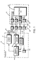
- Fig. 2 is a detailed schematic of a print head circuit of the embodiment of Fig. 1.
- Fig. 3 is graph showing an internal voltage and logic condition plotted against time under different circumstances.
-
- Figure 1 shows a schematic block diagram of an
inkjet printer 10 with a connectedprint cartridge 12. Acontroller 14 in the printer receives print data from a computer or microprocessor (not shown) and processes the data to provide printer control information or image data to a printhead driver circuit 16. A controlledvoltage power supply 17 provides to a four line power bus 18 a controlled supply voltage. Amemory reader circuit 19 in the printer is connected to the controller for transmitting information received from theprint cartridge 12 via amemory line 20. The print head driver circuit is controlled by the controller to send the image data to aprint head die 22 on theprint cartridge 12, via a control bus 24 that has about twenty lines. - The cartridge is removably replaceable, and is electrically connected to the printer by the control bus 24,
power bus 18,memory line 20 and thermal data line to be discussed below. Aconnector interface 26 has a conductive pin for each line on the printer side contacting a corresponding pad on aflexible circuit 30 on thecartridge 12. Amemory chip 31 on the cartridge stores printer control information programmed at production of the cartridge, or by the printer during use. Theflex circuit 30 is connected to the print head die 22 viatab bonds 32. An analog-to-digital converter 34 in the printer is connected to the print head to receive data from the print head that indicates the print head's temperature. - The print head has 524 nozzles, each with an associated firing resistor. The print head is arranged into four similar quadrants, each having eight "primitives" of 16 nozzles each, plus four primitives of three nozzles each. To provide a multiplexed function requiring only a limited number of lines between the printer and print head, resistor current flows through a voltage line and a ground line shared by other resistors in its quadrant. The resistors are individually addressable to provide unlimited pattern permutations, by a serial data stream fed from the print head.
- Figure 2 shows a firing and
energy control circuit 36 of a representative quadrant of the die, and showing an exemplary fraction of the many resistors of the quadrant (an nth one of the sixteen of the full primitive.) Thecircuit 36 resides on the print head die and has a single voltage input line (Vpp) 40 from thepower bus 18 commonly connected to aset 42 of thin film firing resistors 44, each preferably 28Ω. Avoltage sensing network 46 includes ahigh value resistor 50 having ten times the resistance (280Ω) of any of the firing resistors, and connected to theinput line 40 at the same node as the firing resistors. The sensing network further includes aLDMOS switch 52 having an input connected to theresistor 50, an output connected to asense resistor 54 having a low value (10Ω) relative to the firing resistors, and a control line connected to afiring line 56 from the printer. The sense resistor is connected to ground. - A voltage-to-
power converter circuit 60 has aprimary input line 62 connected between theswitch 52 andsense resistor 54. A firing input is connected to thefiring line 56, so that a pulse on the firing line triggers the converter's operation. The converter includes a biascurrent generator 64 and anintegration capacitor 66. A voltage provided to the converter is converted to a power signal, which is used to generate a bias current that is fed to the integration capacitor, creating an output voltage that is proportional to energy. A quadrant slope adjuster (QSA)circuit 68 has an output connected to the converter circuit to adjust its rate of output voltage increase, or output slope, stored in the QSA register, having been loaded from the printer controller, this data having been received from the memory chip. In the preferred embodiment, each QSA provides a +/-5% adjustment in the slope, so that small variations in performance and energy requirements among the quadrants may be controlled and compensated for. Each quadrant has its own such QSA, so that each may be adjusted slightly. A wider adjustment range may be implemented where desired. - A pulse
width control block 70 includes logic for pulse width truncation and a continuous-time voltage comparator has a first input connected to the output of the converter 60 (which transmits the energy signal), a second input connected to the output of a DAC, which is in turn controlled by a setpointvoltage reference device 72, and a control line connected to thefiring line 56. The control block's comparator has anoutput line 74 that transmits a voltage pulse, which is initiated upon triggering by a pulse on the firing line, and when the output of theconverter 60 equals the output of theconverter 80, or when the fire pulse terminates, whichever occurs first. A truncation detect signal on a secondcomparator output line 75 provides status information to control logic circuitry indicating that the circuit has truncated the fire pulse. This signal is used for calibration purposes. - The setpoint
reference voltage device 72 includes a 7-line bus 76 connected to an internal register loaded by the printer, and a 7-bit digital-to-analog-converter (DAC) 80 connected to convert a digitally encoded voltage value received from the printer to a reference voltage output. Theconverter 80 has an output voltage that allows a delivered energy range of 1µJ to 7µJ. In the preferred embodiment, theconverter 80 is a precision poly resistor string combined with an analog switch matrix. - Each firing resistor 44 is connected to a
corresponding firing switch 82 connected to a ground line, and having a control input connected to the output of afire pulse modulator 84. The fire pulse modulator receives print data on a 9 bit bus, and outputs a firing signal to each selected firing switch. - In operation, the system is calibrated as discussed below to set a Vpp level adequate to ensure adequate firing energy levels for full drop volume firing in "blackout conditions" when all resistors are fired simultaneously. Because firing energy is proportional to the product of the square of the voltage and the time duration, Vpp must be high enough to provide adequate energy within the limited time afforded for printing each dot, before the next dot is to be printed at the desired printer scan rate. Part of the calibration process includes establishing a setpoint voltage to provide a limited firing energy threshold for all firing condition, regardless of the number of nozzles fired simultaneously.
- To fire a selected group of the resistor set 42, the printer sends a voltage Vpp on
line 40, and transmits a full-duration firing pulse online 56. In response to the firing pulse, the comparator transmits the firing pulse to the resistor firing switches 82, causing the selected switches to close, connecting the resistors to ground for current flow to generate firing energy. Also in response to initiation of the firing pulse online 56, theswitch 52 opens, allowing a small current to flow throughresistors line 62 being proportional to the Vpp online 40 as affected by the current drawn by the activated resistors. - The firing pulse also triggers the
converter circuit 60 to reset the capacitor to zero, zeroing the output voltage. The input voltage is converted to a power signal by conventional analog circuitry. The power signal is then used to generate a bias current that is fed into theintegration capacitor 66, creating an output voltage ramp with a slope proportional to the energy dissipated during the pulse. The rate of voltage rise is further modified based on the stored data in the quadrantslope adjustment circuit 68, which has been based on initial manufacturing calibrations discussed below. - When the output voltage reaches a preselected setpoint voltage determined experimentally at operational calibration (as will be discussed below,) the comparator of
control block 70 terminates the pulse transmitted online 74 to the firing resistors. In this process, when Vpp is higher due only to a limited number of resistors being selected for firing, the voltage atline 62 will be higher, and the rate of charging of the capacitor will be increased. Consequently, the pulse will be terminated after a shorter duration to maintain a consistent energy delivered. In the event that Vpp drops below the point determined during calibration, and the capacitor voltage does not reach the setpoint before the printer firing pulse ends, the printer fire pulse will override the comparator and terminate energy delivery. It is possible to compensate for such low Vpp conditions by lengthening the firing pulse slightly after calibration, as long as the requirements of pen frequency and printing speed are not violated. - To operationally calibrate an installed print head cartridge to compensate for parasitic resistances in the printer and the printer-to-cartridge connection, Vpp is set by the printer to a default value based on a test operation in which nozzles are fired one quadrant at a time to generate the worst case possible parasitic voltage drops at the input lines for each of the sets of resistors across all of the primitives at its maximum firing frequency. As the printer must have adequately fast throughput and carriage scan speed, the voltage is set with a firing pulse somewhat briefer than the desired time between pulses (i.e. less than [scan speed/dot pitch] + margin). With this nominal maximum pulse duration, the default voltage is set to ensure that all nozzles are firing fully, above the transitional range discussed in the background of the invention. The determination of proper firing and function above the transitional range is conducted by means well known in the field of thermal ink jet printing.
- With a default Vpp established, an energy calibration mode is enabled. In this mode, the energy control circuitry, including the
sense network 46,converter 64, and controlblock 70 are activated. The printer again delivers signals to generate firing from all nozzles of all primitives with the setpoint voltage set at a relatively high initial level Vs1 to provide a high firing energy well beyond the transitional range. This process is repeated at sequentially lower setpoint voltages Vs2, Vs3, etc. until the onset of pulse width truncation indicates that an optimum firing energy level has been reached. This is achieved by firing a pulse at nominal voltage, then checking a truncation status bit indicating whether a pulse was properly fired, then lowering the voltage by a small increment, and repeating the process. During this calibration process, the status bit is set when the firing pulse is still high or active when the comparator trips. If the firing pulse drops or terminates before the comparator trips, the status bit is not set. When the voltage is at a low enough level, firing will not occur, and conventional printer drop sensing circuitry, which may include optical drop detectors, will set the status bit to a state indicating non-firing. The setpoint voltage is set above this non-firing voltage by a margin of safety to ensure firing. Preferably, the setpoint voltage is set so that the firing pulse duration is no longer than 2 µs, to avoid reliability problems associated with longer duration low voltage pulses. Such reliability problems arise when a too-high power is applied during a short duration to obtain the needed energy. Such extreme power creates high rates of temperature change in the resistors, which generates potentially damaging stresses. Optionally, the operational calibration process may continue until a sufficiently low setpoint is reached so that all quadrants are experiencing pulse truncation, thereby ensuring that none of the quadrants are firing at higher than needed energy levels. Ensuring truncation throughout the system also provides a margin for pulse expansion in unexpectedly low Vpp conditions. - Figure 3 illustrates how operational calibration and printing occur. In the upper portion of the graph, the vertical axis reflects the voltage at the
converter 64 output. As shown, the solid line "n" reflects a rising voltage as energy is dissipated by all n resistors firing. During calibration, the setpoint voltage is stepped down as shown until a suitable pulse width and printing performance is attained at Vs3. The voltage line n reaches the selected setpoint at time t1, terminating the pulse P1 as shown in the lower portion of the graph, which reflects the pulse output to the firing resistors atline 74. During subsequent operation after calibration, when less than all resistors are fired, such as with line (n-1) reflecting all resistors fired but one, the slope of the voltage line is steeper, causing it to reach the selected setpoint voltage Vs3 at an earlier time t2, providing a truncated pulse having duration P2 to compensate for the increased Vpp and yield a consistent firing energy. - Prior to delivery and use, the pen undergoes a one-time factory calibration process to compensate for quadrant-to quadrant variations within the pen cartridge. in pen resistors and internal trace resistances. Although the resistances in the printer, and in the power connections between the printer carriage and the pen tend to differ from printer to printer, and with different installations of the same pen in the same printer, the variations internal to a given pen are best identified and compensated for as an end manufacturing process. Internal pen variables include pen flex circuit power and ground line resistance, flex circuit-to-die tab bond resistance, die traces connecting each quadrant to power and to ground, and semiconductor process and resistor variations. Compensating for these variables at manufacturing minimizes the diagnostic circuitry requirements of the printer, and limits calibration delays upon pen installation by the user.
- Factory calibration serves to identify the operational differences between the four functional quadrants of the print head die, in particular the different resistances in the traces and connections for each different quadrant. Also, the resistor dimensions may vary within tolerances, and these variations may tend to be consistent within each quadrant, and different between quadrants. In addition, the semiconductor manufacturing process may generate variations that are minimal within each quadrant, but which create variations within each die, from quadrant to quadrant.
- Calibration of the print head is made at an energy level somewhat in excess of the nominal firing energy, so that any unexpected resistances, such as caused by a marginally poor cartridge-to-printer connection, may be compensated for. The nominally excessive energy is compensated for by the pulse width truncation approach discussed above. In the preferred embodiment, an "over energy" level of 20%, or 1.2 times nominal, is selected.
- Initially, with the energy compensation circuit turned off (so that truncation does not occur), the pulse width is set to 2.0µsec, a maximum nominal pulse width. At this pulse width, each quadrant of the pen is separately operated with all of its nozzles firing, with the other three quadrants inactive. The turn on voltage of each quadrant is determined, and the quadrant with the highest turn on voltage Vh is identified.
- Factory calibration continues by turning on the energy compensation circuit. The
QSA 68 in the highest voltage quadrant (with voltage Vh) is set at the maximum +5% by manufacturing circuitry connected to the cartridge by the standard printer connections. The voltage Vpp on the power line to the high quadrant is set at Vpp=Vh√1.2 (the 1.2 being based on the desired "over energy" level of 1.2 times nominal.) While firing all the resistors of this quadrant only, theDAC 80 is adjusted in a binary search mode until the pulse width for the quadrant begins to truncate, that is, at the lowest voltage level at which truncation occurs. The QSA value of +5%, and the determined DAC setting are written to thememory chip 31 by the external manufacturing circuitry. - The remaining quadrants are calibrated one at a time, firing all resistors of the quadrant "x" to determine a turn on voltage Vx. Using the DAC setting established in calibrating the first "Vh" quadrant, the input Vpp is then set at Vpp=Vx√1.2, and the QSA is adjusted by a binary descent mode until the pulse width for that quadrant just truncates. The QSA setting for this quadrant is written to the memory chip, and the process is repeated for each quadrant. Following manufacturing calibration, the memory chip contains a single DAC setting, and four independent QSA settings, one for each quadrant.
- Factory calibration includes storing a nominal operating voltage Vop, which is used to enable the printer in which the pen is eventually installed to determine whether there are intolerably high parasitic resistances that were not detectable in the pen alone during factory calibration. Such resistances might occur with a printer wiring fault, or a poor conduction at the pen-printer contacts. If a high resistance were encountered, the system circuitry would compensate with a higher input voltage Vpp. This is acceptable up to a point, but a high Vpp needed to overcome resistance when all resistors are firing, will lead to a much higher voltage at a single firing resistor. Of course, this can be compensated for by substantial pulse width truncation to achieve controlled energy, but beyond a certain point, the resistor is unable to reliably withstand the power transmitted, as discussed above.
- Therefore, the factory calibration determines Vop by firing all nozzles of all quadrants, and stepping Vpp up until the highest turn on voltage quadrant just truncates. Voltage is stepped down one increment, and this voltage is written as Vop to the memory chip in the pen cartridge. With the memory chip thus programmed, the cartridge may be delivered to a user, either in conjunction with a printer, or as a replacement cartridge.
- When installed in a printer by the user, the printer will perform a test on the pen cartridge to determine the correct power supply voltage Vps for that pen. First, the printer reads the operating voltage Vop from the pen's memory chip, and sets Vps=Vop. Then, the printer operates with all nozzles of all quadrants firing, in blackout mode, and reads the pulse width truncation flags for each quadrant. The power supply voltage Vps is stepped up until all quadrants are truncating, and defines that voltage as Vtrunc. Then, the processor calculates the amount by which Vtrunc (the voltage needed to operate under blackout conditions) exceeds Vop. If this difference is below an acceptable limit stored ion the printer controller, Vps is lowered by a single increment below Vtrunc, and the printer operated at this voltage.
- If the (Vtrunc-Vps) difference exceeds the preselected limit, the pen reliability may be jeopardized by further operation, and the printer generates a fault message advising the user to reinstall the pen cartridge. If the unexpected resistance leading to the excessive Vtrunc was due to a bad contact between printer and cartridge, such as by a particle between contact pin and contact pad, the reinstallation is likely to cure the problem. If reinstallation does not solve the problem, a fault message advises servicing the printer, and may disable printer operation to prevent damage.
- While the above is discussed in terms of preferred and alternative embodiments, the invention is not intended to be so limited.
Claims (10)
- A method of operating a thermal ink jet printer (10) including a removable print head (12) having a plurality of ink firing resistors (42) comprising the steps:calibrating the printer by determining a nominal input voltage (Vs1) above a threshold necessary for simultaneous operation of a plurality of the resistors;during printing, detecting the input voltage on the print head at an input node (40) connected to at least some of the resistors; andshortening a firing pulse (P1), in an energy control circuit connected to the input node and operably connected to the plurality of resistors, to generate a shortened firing pulse (P2) having a duration based on the detected input voltage at the node, such that a detected input voltage higher than the nominal voltage is compensated for by the shortened firing pulse.
- The method of claim 1 wherein calibrating includes sequentially firing at least some of the resistors (44) using progressively lower voltages.
- The method of claim 1 wherein detecting the input voltage includes connecting the input node to a current sensor (46).
- The method of claim 1 wherein generating the firing pulse includes connecting the input node to a capacitive device (64) having an output control voltage that rises in relation to current input.
- The method of claim 1 wherein generating the firing pulse includes initiating the pulse, and while the pulse is continuing to deliver energy to the resistors, generating a rising setpoint voltage proportional to the energy delivered to the resistors, and when the setpoint voltage rises to a preselected threshold, terminating the pulse.
- A removable ink jet print head (12) comprising:a connector having a plurality of electrical inputs (40) connectable to a printer;a voltage input node (40) connected to the connector,a plurality of firing resistors (44) connected to the input node;an energy control circuit (46, 60) connected to the input node and operably connected to the plurality of resistors to fire the resistors with a firing pulse having a duration inversely related to the voltage at the input node, such that firing energy is maintained in control by varying the firing pulse duration to compensate for voltage variations.
- The apparatus of claim 6 wherein the energy control circuit includes a voltage to energy converter (60) for estimating the energy provided to the resistors.
- The apparatus of claim 7 including a voltage comparator (70) having an input connected to the converter, and output operably connected to the resistors to deliver a pulse having a limited duration terminating when the output of the converter rises above a preselected threshold.
- The apparatus of claim 6 wherein the energy control circuit includes a capacitor (64) that accumulates a charge in relation to the voltage at the input node and to the time connected to the input node.
- The apparatus of claim 6 including a firing input (56) operably connected to a switch between the input node and the energy control circuit, such that the energy control circuit is disconnected from the input node until the switch is closed by the leading edge of a firing pulse on the firing input.
Applications Claiming Priority (2)
| Application Number | Priority Date | Filing Date | Title |
|---|---|---|---|
| US08/958,951 US6183056B1 (en) | 1997-10-28 | 1997-10-28 | Thermal inkjet printhead and printer energy control apparatus and method |
| US958951 | 1997-10-28 |
Publications (3)
| Publication Number | Publication Date |
|---|---|
| EP0913255A2 EP0913255A2 (en) | 1999-05-06 |
| EP0913255A3 EP0913255A3 (en) | 2000-04-19 |
| EP0913255B1 true EP0913255B1 (en) | 2003-05-02 |
Family
ID=25501481
Family Applications (1)
| Application Number | Title | Priority Date | Filing Date |
|---|---|---|---|
| EP98307724A Expired - Lifetime EP0913255B1 (en) | 1997-10-28 | 1998-09-23 | Thermal ink jet print head energy control apparatus and method |
Country Status (4)
| Country | Link |
|---|---|
| US (1) | US6183056B1 (en) |
| EP (1) | EP0913255B1 (en) |
| JP (1) | JP4489856B2 (en) |
| DE (1) | DE69813990T2 (en) |
Cited By (8)
| Publication number | Priority date | Publication date | Assignee | Title |
|---|---|---|---|---|
| US7090338B2 (en) | 1999-07-30 | 2006-08-15 | Hewlett-Packard Development Company, L.P. | Fluid ejection device with fire cells |
| WO2007065187A1 (en) * | 2005-12-05 | 2007-06-14 | Silverbrook Research Pty Ltd | Method of modulating printhead peak power requirement using redundant nozzles |
| US7438371B2 (en) | 2005-12-05 | 2008-10-21 | Silverbrook Research Pty Ltd | Method of modulating printhead peak power requirement using redundant nozzles |
| US7441862B2 (en) | 2005-12-05 | 2008-10-28 | Silverbrook Research Pty Ltd | Method of modulating printhead peak power requirement using out-of-phase firing |
| US7455376B2 (en) | 2005-12-05 | 2008-11-25 | Silverbrook Research Pty Ltd | Printhead system for modulating printhead peak power requirement using out-of-phase firing |
| US7458659B2 (en) | 2005-12-05 | 2008-12-02 | Silverbrook Research Pty Ltd | Printer controller for modulating printhead peak power requirement using redundant nozzles |
| US7465017B2 (en) | 2005-12-05 | 2008-12-16 | Silverbrook Research Pty Ltd | Dot-at-a-time redundancy for modulating printhead peak power requirement |
| US7654636B2 (en) | 2005-12-05 | 2010-02-02 | Silverbrook Research Pty Ltd | Inkjet printhead having optimal number of printhead modules and nozzle rows for out-of-phase printing |
Families Citing this family (37)
| Publication number | Priority date | Publication date | Assignee | Title |
|---|---|---|---|---|
| US6290333B1 (en) * | 1997-10-28 | 2001-09-18 | Hewlett-Packard Company | Multiple power interconnect arrangement for inkjet printhead |
| US6536871B1 (en) * | 1997-11-05 | 2003-03-25 | Hewlett-Packard Company | Reliable flex circuit interconnect on inkjet print cartridge |
| JP3976907B2 (en) * | 1998-09-21 | 2007-09-19 | キヤノン株式会社 | Recording head and recording apparatus using the recording head |
| AUPP702498A0 (en) * | 1998-11-09 | 1998-12-03 | Silverbrook Research Pty Ltd | Image creation method and apparatus (ART77) |
| US6755495B2 (en) | 2001-03-15 | 2004-06-29 | Hewlett-Packard Development Company, L.P. | Integrated control of power delivery to firing resistors for printhead assembly |
| US6729707B2 (en) * | 2002-04-30 | 2004-05-04 | Hewlett-Packard Development Company, L.P. | Self-calibration of power delivery control to firing resistors |
| JP2000343702A (en) * | 1999-06-04 | 2000-12-12 | Canon Inc | Liquid ejecting head and liquid ejecting device using the liquid ejecting head |
| US6439697B1 (en) | 1999-07-30 | 2002-08-27 | Hewlett-Packard Company | Dynamic memory based firing cell of thermal ink jet printhead |
| JP2002096470A (en) * | 1999-08-24 | 2002-04-02 | Canon Inc | Device for recording, nethod for controlling the same, and computer readable memory |
| US6520615B1 (en) * | 1999-10-05 | 2003-02-18 | Hewlett-Packard Company | Thermal inkjet print head with integrated power supply fault protection circuitry for protection of firing circuitry |
| JP3442027B2 (en) * | 2000-03-28 | 2003-09-02 | キヤノン株式会社 | Ink jet recording head and ink jet recording apparatus |
| US6523935B2 (en) * | 2001-01-30 | 2003-02-25 | Hewlett-Packard Company | Narrow ink jet printhead |
| DE60205423T2 (en) | 2001-04-27 | 2006-04-13 | Canon K.K. | Printing device and pressure control method |
| US6758547B2 (en) | 2002-07-10 | 2004-07-06 | Lexmark International, Inc. | Method and apparatus for machine specific overcurrent detection |
| US6779862B2 (en) | 2002-09-12 | 2004-08-24 | Hewlett-Packard Development, L.P. | System and method of providing power to a print head |
| US6669324B1 (en) | 2002-11-25 | 2003-12-30 | Lexmark International, Inc. | Method and apparatus for optimizing a relationship between fire energy and drop velocity in an imaging device |
| US6825675B1 (en) | 2003-06-27 | 2004-11-30 | Lexmark International, Inc. | Method for detecting a shorted printhead in a printer having at least two printheads |
| US20050097385A1 (en) * | 2003-10-15 | 2005-05-05 | Ahne Adam J. | Method of fault correction for an array of fusible links |
| US6976752B2 (en) * | 2003-10-28 | 2005-12-20 | Lexmark International, Inc. | Ink jet printer with resistance compensation circuit |
| US7175248B2 (en) * | 2004-02-27 | 2007-02-13 | Hewlett-Packard Development Company, L.P. | Fluid ejection device with feedback circuit |
| US7240981B2 (en) * | 2004-02-27 | 2007-07-10 | Hewlett-Packard Development Company, L.P. | Wide array fluid ejection device |
| US7390070B2 (en) * | 2004-06-04 | 2008-06-24 | Brother Kogyo Kabushiki Kaisha | Ink-jet printer |
| US20060176326A1 (en) * | 2005-02-09 | 2006-08-10 | Benq Corporation | Fluid injector devices and methods for utilizing the same |
| US7419231B2 (en) * | 2005-05-25 | 2008-09-02 | Lexmark International, Inc. | Power sensing circuit |
| WO2007035803A2 (en) * | 2005-09-20 | 2007-03-29 | Zink Imaging, Llc | Thermal print head temperature estimation system |
| US20070126761A1 (en) * | 2005-12-05 | 2007-06-07 | Silverbrook Research Pty Ltd | Printhead system for modulating printhead peak power requirement using redundant nozzles |
| JP4144637B2 (en) | 2005-12-26 | 2008-09-03 | セイコーエプソン株式会社 | Printing material container, substrate, printing apparatus, and method for preparing printing material container |
| US7661782B2 (en) * | 2007-04-19 | 2010-02-16 | Lexmark International, Inc. | Current control circuit for micro-fluid ejection device heaters |
| US8702191B2 (en) | 2012-07-05 | 2014-04-22 | Hewlett-Packard Development Company, L.P. | Printer control method and system |
| EP3134271B1 (en) | 2014-04-23 | 2020-02-19 | Hewlett-Packard Development Company, L.P. | Evaluating print head nozzle condition |
| WO2016068849A1 (en) | 2014-10-27 | 2016-05-06 | Hewlett-Packard Development Company, L.P. | Printing device |
| US9415585B1 (en) | 2015-07-29 | 2016-08-16 | Hewlett-Packard Development Company, L. P. | Dynamic power thresholds for printer device pens |
| US10368581B2 (en) * | 2016-03-11 | 2019-08-06 | Altria Client Services Llc | Multiple dispersion generator e-vaping device |
| GB2552979B (en) | 2016-08-17 | 2022-05-25 | Sweven Design Ltd | Driving variable capacitive loads |
| US11764776B2 (en) | 2016-08-17 | 2023-09-19 | Sweven Design Ltd. | Zero excess energy storage transformer |
| WO2018067155A1 (en) | 2016-10-06 | 2018-04-12 | Hewlett-Packard Development Company, L.P. | Input control signals propagated over signal paths |
| US11318737B2 (en) | 2018-07-02 | 2022-05-03 | Hewlett-Packard Development Company, L.P. | Fluidic die with fire signal adjustment |
Family Cites Families (33)
| Publication number | Priority date | Publication date | Assignee | Title |
|---|---|---|---|---|
| DE2928304C2 (en) | 1978-07-18 | 1983-01-13 | Oki Electric Industry Co., Ltd., Tokyo | Control circuit for maintaining constant color intensity in a thermal recording apparatus |
| US4490728A (en) | 1981-08-14 | 1984-12-25 | Hewlett-Packard Company | Thermal ink jet printer |
| JPS6013571A (en) * | 1983-07-04 | 1985-01-24 | Sony Corp | Printer |
| JPS60206664A (en) * | 1984-03-31 | 1985-10-18 | Canon Inc | Liquid jet recording device |
| JPH069920B2 (en) * | 1985-02-28 | 1994-02-09 | キヤノン株式会社 | Inkjet recording device |
| US4791435A (en) | 1987-07-23 | 1988-12-13 | Hewlett-Packard Company | Thermal inkjet printhead temperature control |
| US5068674A (en) * | 1988-06-07 | 1991-11-26 | Canon Kabushiki Kaisha | Liquid jet recording head stabilization |
| US5036377A (en) * | 1988-08-03 | 1991-07-30 | Texas Instruments Incorporated | Triac array |
| JPH0332844A (en) * | 1989-06-30 | 1991-02-13 | Canon Inc | Liquid jet recording head |
| USRE36279E (en) * | 1990-02-02 | 1999-08-24 | Canon Kabushiki Kaisha | Ink jet apparatus and ink jet cartridge therefor |
| US5072235A (en) * | 1990-06-26 | 1991-12-10 | Xerox Corporation | Method and apparatus for the electronic detection of air inside a thermal inkjet printhead |
| US5109234A (en) | 1990-09-14 | 1992-04-28 | Hewlett-Packard Company | Printhead warming method to defeat wait-time banding |
| US5083137A (en) * | 1991-02-08 | 1992-01-21 | Hewlett-Packard Company | Energy control circuit for a thermal ink-jet printhead |
| US5726690A (en) * | 1991-05-01 | 1998-03-10 | Hewlett-Packard Company | Control of ink drop volume in thermal inkjet printheads by varying the pulse width of the firing pulses |
| JPH05301370A (en) * | 1992-04-24 | 1993-11-16 | Oki Electric Ind Co Ltd | Thermal head |
| DE69307590T2 (en) | 1992-05-11 | 1997-05-15 | Hewlett Packard Co | Method and device for printing density control in an inkjet printer |
| JP3264694B2 (en) * | 1992-06-16 | 2002-03-11 | キヤノン株式会社 | Ink jet recording head and ink jet recording method |
| US5691750A (en) * | 1992-11-24 | 1997-11-25 | Lexmark International, Inc. | Ink level sensing for disposable ink jet print head cartridges |
| JPH06286139A (en) * | 1993-04-07 | 1994-10-11 | Nec Corp | Ink jet printer |
| US5418558A (en) | 1993-05-03 | 1995-05-23 | Hewlett-Packard Company | Determining the operating energy of a thermal ink jet printhead using an onboard thermal sense resistor |
| US5428376A (en) | 1993-10-29 | 1995-06-27 | Hewlett-Packard Company | Thermal turn on energy test for an inkjet printer |
| US5682185A (en) * | 1993-10-29 | 1997-10-28 | Hewlett-Packard Company | Energy measurement scheme for an ink jet printer |
| US5475405A (en) | 1993-12-14 | 1995-12-12 | Hewlett-Packard Company | Control circuit for regulating temperature in an ink-jet print head |
| US5497174A (en) * | 1994-03-11 | 1996-03-05 | Xerox Corporation | Voltage drop correction for ink jet printer |
| US5521620A (en) * | 1994-05-20 | 1996-05-28 | Xerox Corporation | Correction circuit for an ink jet device to maintain print quality |
| EP0703079B1 (en) * | 1994-09-23 | 1999-03-17 | Hewlett-Packard Company | Reducing energy variations in thermal ink jet printheads |
| US5754193A (en) * | 1995-01-09 | 1998-05-19 | Xerox Corporation | Thermal ink jet printhead with reduced power bus voltage drop differential |
| JPH08276572A (en) * | 1995-04-07 | 1996-10-22 | Sharp Corp | Ink jet printer and adjustment thereof |
| JPH0911463A (en) * | 1995-06-28 | 1997-01-14 | Fuji Xerox Co Ltd | Ink-jet recording device, its driving device, and ink-jet recording method |
| JP3590702B2 (en) * | 1995-11-16 | 2004-11-17 | 富士写真フイルム株式会社 | Method and apparatus for measuring resistance data of thermal head and thermal printer having the same |
| US5751302A (en) * | 1996-03-29 | 1998-05-12 | Xerox Corporation | Transducer power dissipation control in a thermal ink jet printhead |
| JPH1024584A (en) * | 1996-07-12 | 1998-01-27 | Canon Inc | Liquid discharge head cartridge and liquid discharge device |
| US6039430A (en) * | 1998-06-05 | 2000-03-21 | Hewlett-Packard Company | Method and apparatus for storing and retrieving information on a replaceable printing component |
-
1997
- 1997-10-28 US US08/958,951 patent/US6183056B1/en not_active Expired - Lifetime
-
1998
- 1998-09-23 EP EP98307724A patent/EP0913255B1/en not_active Expired - Lifetime
- 1998-09-23 DE DE69813990T patent/DE69813990T2/en not_active Expired - Lifetime
- 1998-10-28 JP JP30700198A patent/JP4489856B2/en not_active Expired - Fee Related
Cited By (13)
| Publication number | Priority date | Publication date | Assignee | Title |
|---|---|---|---|---|
| US7090338B2 (en) | 1999-07-30 | 2006-08-15 | Hewlett-Packard Development Company, L.P. | Fluid ejection device with fire cells |
| WO2007065187A1 (en) * | 2005-12-05 | 2007-06-14 | Silverbrook Research Pty Ltd | Method of modulating printhead peak power requirement using redundant nozzles |
| US7438371B2 (en) | 2005-12-05 | 2008-10-21 | Silverbrook Research Pty Ltd | Method of modulating printhead peak power requirement using redundant nozzles |
| US7441862B2 (en) | 2005-12-05 | 2008-10-28 | Silverbrook Research Pty Ltd | Method of modulating printhead peak power requirement using out-of-phase firing |
| US7455376B2 (en) | 2005-12-05 | 2008-11-25 | Silverbrook Research Pty Ltd | Printhead system for modulating printhead peak power requirement using out-of-phase firing |
| US7458659B2 (en) | 2005-12-05 | 2008-12-02 | Silverbrook Research Pty Ltd | Printer controller for modulating printhead peak power requirement using redundant nozzles |
| US7465017B2 (en) | 2005-12-05 | 2008-12-16 | Silverbrook Research Pty Ltd | Dot-at-a-time redundancy for modulating printhead peak power requirement |
| US7654636B2 (en) | 2005-12-05 | 2010-02-02 | Silverbrook Research Pty Ltd | Inkjet printhead having optimal number of printhead modules and nozzle rows for out-of-phase printing |
| US7896465B2 (en) | 2005-12-05 | 2011-03-01 | Silverbrook Research Pty Ltd | Inkjet printhead with a printer controller for controlling nozzle firing sequence |
| US7918522B2 (en) | 2005-12-05 | 2011-04-05 | Silverbrook Research Pty Ltd | Printhead system for modulating printhead peak power requirement using redundant nozzles |
| US7984966B2 (en) | 2005-12-05 | 2011-07-26 | Silverbrook Research Pty Ltd | Inkjet printhead with matched number of color channels and printhead modules |
| US8066346B2 (en) | 2005-12-05 | 2011-11-29 | Silverbrook Research Pty Ltd | Printer controller for modulating printhead peak power requirement using out-of phase firing |
| US8075097B2 (en) | 2005-12-05 | 2011-12-13 | Silverbrook Research Pty Ltd | Method of modulating peak power requirement of modular printhead |
Also Published As
| Publication number | Publication date |
|---|---|
| DE69813990T2 (en) | 2004-03-11 |
| US6183056B1 (en) | 2001-02-06 |
| EP0913255A2 (en) | 1999-05-06 |
| JP4489856B2 (en) | 2010-06-23 |
| JPH11192702A (en) | 1999-07-21 |
| DE69813990D1 (en) | 2003-06-05 |
| EP0913255A3 (en) | 2000-04-19 |
Similar Documents
| Publication | Publication Date | Title |
|---|---|---|
| EP0913255B1 (en) | Thermal ink jet print head energy control apparatus and method | |
| EP0953446B1 (en) | Energy control method for an inkjet print cartridge | |
| US6575548B1 (en) | System and method for controlling energy characteristics of an inkjet printhead | |
| US6565177B1 (en) | System and method for controlling thermal characteristics of an inkjet printhead | |
| EP0650837B1 (en) | Energy management scheme for an ink-jet printer | |
| US6302507B1 (en) | Method for controlling the over-energy applied to an inkjet print cartridge using dynamic pulse width adjustment based on printhead temperature | |
| US6318828B1 (en) | System and method for controlling firing operations of an inkjet printhead | |
| US5576745A (en) | Recording apparatus having thermal head and recording method | |
| US6536871B1 (en) | Reliable flex circuit interconnect on inkjet print cartridge | |
| EP1029685A2 (en) | A high performance printing system and protocol | |
| US6290333B1 (en) | Multiple power interconnect arrangement for inkjet printhead | |
| US7625056B2 (en) | Device and method for driving jetting head | |
| EP1193065B1 (en) | Ink jet printing apparatus and ink jet printing method | |
| JP2000238247A (en) | Print head assembly | |
| JPH071736A (en) | Method for determining actuating energy of thermal ink jet printing head using on-board heat sensing resistor | |
| US7029087B2 (en) | Head driving device of liquid ejecting apparatus | |
| KR101093481B1 (en) | Fluid ejection device identification | |
| JPH02289354A (en) | Liquid jet recording head, substrate for same recording head, and recorder | |
| US6481823B1 (en) | Method for using highly energetic droplet firing events to improve droplet ejection reliability | |
| US6886903B2 (en) | Determination of turn-on energy for a printhead |
Legal Events
| Date | Code | Title | Description |
|---|---|---|---|
| PUAI | Public reference made under article 153(3) epc to a published international application that has entered the european phase |
Free format text: ORIGINAL CODE: 0009012 |
|
| AK | Designated contracting states |
Kind code of ref document: A2 Designated state(s): DE FR GB IT |
|
| AX | Request for extension of the european patent |
Free format text: AL;LT;LV;MK;RO;SI |
|
| PUAL | Search report despatched |
Free format text: ORIGINAL CODE: 0009013 |
|
| AK | Designated contracting states |
Kind code of ref document: A3 Designated state(s): AT BE CH CY DE DK ES FI FR GB GR IE IT LI LU MC NL PT SE |
|
| AX | Request for extension of the european patent |
Free format text: AL;LT;LV;MK;RO;SI |
|
| 17P | Request for examination filed |
Effective date: 20000926 |
|
| AKX | Designation fees paid |
Free format text: DE FR GB IT |
|
| RAP1 | Party data changed (applicant data changed or rights of an application transferred) |
Owner name: HEWLETT-PACKARD COMPANY, A DELAWARE CORPORATION |
|
| 17Q | First examination report despatched |
Effective date: 20011011 |
|
| GRAH | Despatch of communication of intention to grant a patent |
Free format text: ORIGINAL CODE: EPIDOS IGRA |
|
| GRAH | Despatch of communication of intention to grant a patent |
Free format text: ORIGINAL CODE: EPIDOS IGRA |
|
| GRAA | (expected) grant |
Free format text: ORIGINAL CODE: 0009210 |
|
| AK | Designated contracting states |
Designated state(s): DE FR GB IT |
|
| PG25 | Lapsed in a contracting state [announced via postgrant information from national office to epo] |
Ref country code: IT Free format text: LAPSE BECAUSE OF FAILURE TO SUBMIT A TRANSLATION OF THE DESCRIPTION OR TO PAY THE FEE WITHIN THE PRESCRIBED TIME-LIMIT;WARNING: LAPSES OF ITALIAN PATENTS WITH EFFECTIVE DATE BEFORE 2007 MAY HAVE OCCURRED AT ANY TIME BEFORE 2007. THE CORRECT EFFECTIVE DATE MAY BE DIFFERENT FROM THE ONE RECORDED. Effective date: 20030502 |
|
| REG | Reference to a national code |
Ref country code: GB Ref legal event code: FG4D |
|
| REF | Corresponds to: |
Ref document number: 69813990 Country of ref document: DE Date of ref document: 20030605 Kind code of ref document: P |
|
| ET | Fr: translation filed | ||
| PLBE | No opposition filed within time limit |
Free format text: ORIGINAL CODE: 0009261 |
|
| STAA | Information on the status of an ep patent application or granted ep patent |
Free format text: STATUS: NO OPPOSITION FILED WITHIN TIME LIMIT |
|
| 26N | No opposition filed |
Effective date: 20040203 |
|
| REG | Reference to a national code |
Ref country code: GB Ref legal event code: 732E Free format text: REGISTERED BETWEEN 20120329 AND 20120404 |
|
| PGFP | Annual fee paid to national office [announced via postgrant information from national office to epo] |
Ref country code: GB Payment date: 20120925 Year of fee payment: 15 |
|
| PGFP | Annual fee paid to national office [announced via postgrant information from national office to epo] |
Ref country code: FR Payment date: 20121001 Year of fee payment: 15 |
|
| PGFP | Annual fee paid to national office [announced via postgrant information from national office to epo] |
Ref country code: DE Payment date: 20120927 Year of fee payment: 15 |
|
| GBPC | Gb: european patent ceased through non-payment of renewal fee |
Effective date: 20130923 |
|
| REG | Reference to a national code |
Ref country code: DE Ref legal event code: R119 Ref document number: 69813990 Country of ref document: DE Effective date: 20140401 |
|
| REG | Reference to a national code |
Ref country code: FR Ref legal event code: ST Effective date: 20140530 |
|
| PG25 | Lapsed in a contracting state [announced via postgrant information from national office to epo] |
Ref country code: GB Free format text: LAPSE BECAUSE OF NON-PAYMENT OF DUE FEES Effective date: 20130923 |
|
| PG25 | Lapsed in a contracting state [announced via postgrant information from national office to epo] |
Ref country code: FR Free format text: LAPSE BECAUSE OF NON-PAYMENT OF DUE FEES Effective date: 20130930 Ref country code: DE Free format text: LAPSE BECAUSE OF NON-PAYMENT OF DUE FEES Effective date: 20140401 |