EP0915433A2 - View offset estimation for steroscopic video coding - Google Patents
View offset estimation for steroscopic video coding Download PDFInfo
- Publication number
- EP0915433A2 EP0915433A2 EP98120697A EP98120697A EP0915433A2 EP 0915433 A2 EP0915433 A2 EP 0915433A2 EP 98120697 A EP98120697 A EP 98120697A EP 98120697 A EP98120697 A EP 98120697A EP 0915433 A2 EP0915433 A2 EP 0915433A2
- Authority
- EP
- European Patent Office
- Prior art keywords
- layer image
- image
- lower layer
- enhancement layer
- offset
- Prior art date
- Legal status (The legal status is an assumption and is not a legal conclusion. Google has not performed a legal analysis and makes no representation as to the accuracy of the status listed.)
- Granted
Links
Images


Classifications
-
- H—ELECTRICITY
- H04—ELECTRIC COMMUNICATION TECHNIQUE
- H04N—PICTORIAL COMMUNICATION, e.g. TELEVISION
- H04N19/00—Methods or arrangements for coding, decoding, compressing or decompressing digital video signals
- H04N19/50—Methods or arrangements for coding, decoding, compressing or decompressing digital video signals using predictive coding
- H04N19/597—Methods or arrangements for coding, decoding, compressing or decompressing digital video signals using predictive coding specially adapted for multi-view video sequence encoding
-
- G—PHYSICS
- G06—COMPUTING; CALCULATING OR COUNTING
- G06T—IMAGE DATA PROCESSING OR GENERATION, IN GENERAL
- G06T7/00—Image analysis
- G06T7/97—Determining parameters from multiple pictures
-
- G—PHYSICS
- G06—COMPUTING; CALCULATING OR COUNTING
- G06T—IMAGE DATA PROCESSING OR GENERATION, IN GENERAL
- G06T2207/00—Indexing scheme for image analysis or image enhancement
- G06T2207/10—Image acquisition modality
- G06T2207/10004—Still image; Photographic image
- G06T2207/10012—Stereo images
-
- H—ELECTRICITY
- H04—ELECTRIC COMMUNICATION TECHNIQUE
- H04N—PICTORIAL COMMUNICATION, e.g. TELEVISION
- H04N13/00—Stereoscopic video systems; Multi-view video systems; Details thereof
- H04N13/10—Processing, recording or transmission of stereoscopic or multi-view image signals
- H04N13/106—Processing image signals
- H04N13/161—Encoding, multiplexing or demultiplexing different image signal components
-
- H—ELECTRICITY
- H04—ELECTRIC COMMUNICATION TECHNIQUE
- H04N—PICTORIAL COMMUNICATION, e.g. TELEVISION
- H04N13/00—Stereoscopic video systems; Multi-view video systems; Details thereof
- H04N13/10—Processing, recording or transmission of stereoscopic or multi-view image signals
- H04N13/194—Transmission of image signals
-
- H—ELECTRICITY
- H04—ELECTRIC COMMUNICATION TECHNIQUE
- H04N—PICTORIAL COMMUNICATION, e.g. TELEVISION
- H04N13/00—Stereoscopic video systems; Multi-view video systems; Details thereof
- H04N13/20—Image signal generators
- H04N13/204—Image signal generators using stereoscopic image cameras
- H04N13/239—Image signal generators using stereoscopic image cameras using two 2D image sensors having a relative position equal to or related to the interocular distance
-
- H—ELECTRICITY
- H04—ELECTRIC COMMUNICATION TECHNIQUE
- H04N—PICTORIAL COMMUNICATION, e.g. TELEVISION
- H04N13/00—Stereoscopic video systems; Multi-view video systems; Details thereof
- H04N2013/0074—Stereoscopic image analysis
- H04N2013/0081—Depth or disparity estimation from stereoscopic image signals
Landscapes
- Engineering & Computer Science (AREA)
- Multimedia (AREA)
- Signal Processing (AREA)
- Computer Vision & Pattern Recognition (AREA)
- Physics & Mathematics (AREA)
- General Physics & Mathematics (AREA)
- Theoretical Computer Science (AREA)
- Compression Or Coding Systems Of Tv Signals (AREA)
- Testing, Inspecting, Measuring Of Stereoscopic Televisions And Televisions (AREA)
Abstract
Description
- The present invention relates to an apparatus and method for coding stereoscopic video data. In particular, a system for estimating the optimal offset of a scene between right and left channel views at the same temporal reference point is presented. The system reduces the motion vector search range for disparity (i.e., cross-channel or cross-layer) prediction to improve coding efficiency.
- Digital technology has revolutionized the delivery of video and audio services to consumers since it can deliver signals of much higher quality than analog techniques and provide additional features that were previously unavailable. Digital systems are particularly advantageous for signals that are broadcast via a cable television network or by satellite to cable television affiliates and/or directly to home satellite television receivers. In such systems, a subscriber receives the digital data stream via a receiver/descrambler that decompresses and decodes the data in order to reconstruct the original video and audio signals. The digital receiver includes a microcomputer and memory storage elements for use in this process.
- The need to provide low cost receivers while still providing high quality video and audio requires that the amount of data which is processed be limited. Moreover, the available bandwidth for the transmission of the digital signal may also be limited by physical constraints, existing communication protocols, and governmental regulations. Accordingly, various intra-frame data compression schemes have been developed that take advantage of the spatial correlation among adjacent pixels in a particular video picture (e.g., frame).
- Moreover, inter-frame compression schemes take advantage of temporal correlations between corresponding regions of successive frames by using motion compensation data and block-matching motion estimation algorithms. In this case, a motion vector is determined for each block in a current picture of an image by identifying a block in a previous picture which most closely resembles the current block. The entire current picture can then be reconstructed at a decoder by sending data which represents the difference between the corresponding block pairs, together with the motion vectors that are required to identify the corresponding pairs. Block matching motion estimating algorithms are particularly effective when combined with block-based spatial compression techniques such as the discrete cosine transform (DCT).
- Additionally, there has been increasing interest in proposed stereoscopic video transmission formats such as the Motion Picture Experts Group (MPEG) MPEG-2 Multi-view Profile (MVP) system, described in document ISO/IEC JTC1/SC29/WG11 N1088 (ITU-T Recommendation H.262), entitled "Proposed Draft Amendment No. 3 to 13818-2 (Multi-view Profile)," November 1995, and its
amendment 3; as well as the MPEG-4 Video Verification Model (VM) Version 3.0, described in document ISO/IEC JTC1/SC29/WG11 N1277, Tampere, Finland, July 1996, both of which are incorporated herein by reference. - Stereoscopic video provides slightly offset views of the same image to produce a combined image with greater depth of field, thereby creating a three-dimensional (3-D) effect. In such a system, dual cameras may be positioned about 2.5 inches, or 65 mm, apart to record an event on two separate video signals. The spacing of the cameras approximates the distance between left and right human eyes, i.e., the inter-ocular separation. Moreover, with some stereoscopic video camcorders, the two lenses are built into one camcorder head and therefore move in synchronism, for example, when panning across an image. The two video signals can be transmitted and recombined at a receiver to produce an image with a depth of field that corresponds to normal human vision. Other special effects can also be provided.
- The MPEG MVP system includes two video layers which are transmitted in a multiplexed signal. First, a base (e.g., lower) layer represents a left view of a three dimensional object. Second, an enhancement (e.g., auxiliary, or upper) layer represents a right view of the object. Since the right and left views are of the same object and are offset only slightly relative to each other, there will usually be a large degree of correlation between the video images of the base and enhancement layers. This correlation can be used to compress the enhancement layer data relative to the base layer, thereby reducing the amount of data that needs to be transmitted in the enhancement layer to maintain a given image quality. The image quality generally corresponds to the quantization level of the video data.
- The MPEG MVP system includes three types of video pictures; specifically, the intra-coded picture (I-picture), predictive-coded picture (P-picture), and bi-directionally predictive-coded picture (B-picture). Furthermore, while the base layer accommodates either frame or field structure video sequences, the enhancement layer accommodates only frame structure. An I-picture completely describes a single video picture without reference to any other picture. For improved error concealment, motion vectors can be included with an I-picture. An error in an I-picture has the potential for greater impact on the displayed video since both P-pictures and B-pictures in the base layer are predicted from I-pictures. Moreover, pictures in the enhancement layer can be predicted from pictures in the base layer in a cross-layer prediction process known as disparity prediction. Prediction from one frame to another within a layer is known as temporal prediction.
- In the base layer, P pictures are predicted based on previous I or P pictures. The reference is from an earlier I or P picture to a future P-picture and is known as forward prediction. B-pictures are predicted from the closest earlier I or P picture and the closest later I or P picture.
- In the enhancement layer, a P-picture can be predicted from (a) the most recently decoded picture in the enhancement layer, (b) the most recent base layer picture, in display order, or (c) the next lower layer picture, in display order. Case (b) is used usually when the most recent base layer picture, in display order, is an I-picture.
- Moreover, a B-picture in the enhancement layer can be predicted using (d) the most recent decoded enhancement layer picture for forward prediction, and the most recent lower layer picture, in display order, (e) the most recent decoded enhancement layer picture for forward prediction, and the next lower layer picture, in display order, for backward prediction, or (f) the most recent lower layer picture, in display order, for forward prediction, and the next lower layer picture, in display order, for backward prediction. When the most recent lower layer picture, in display order, is an I-picture, only that I-picture will be used for predictive coding (e.g., there will be no forward prediction).
- Note that only prediction modes (a), (b) and (d) are encompassed within the MPEG MVP system. The MVP system is a subset of MPEG temporal scalability coding, which encompasses each of modes (a)-(f).
- In one optional configuration, the enhancement layer has only P and B pictures, but no I pictures. The reference to a future picture (i.e., one that has not yet been displayed) is called backward prediction. Note that no backward prediction occurs within the enhancement layer. Accordingly, enhancement layer pictures are transmitted in display order. There are situations where backward prediction is very useful in increasing the compression rate. For example, in a scene in which a door opens, the current picture may predict what is behind the door based upon a future picture in which the door is already open.
- B-pictures yield the most compression but also incorporate the most error. To eliminate error propagation, B-pictures may never be predicted from other B-pictures in the base layer. P-pictures yield less error and less compression. I-pictures yield the least compression, but are able to provide random access.
- For disparity prediction, e.g., where a lower layer image is used as a reference image for an enhancement layer image, either alone or in combination with an enhancement layer reference image. The enhancement layer image is motion compensated by finding a best-match image in the reference image by searching a predefined search area, then differentially encoding the pixels of the enhancement layer image using the pixels of the best-match image of the reference image. A motion vector which defines the relative displacement of the best match image to the coded enhancement layer region is transmitted with the differentially encoded pixel data to allow reconstruction of the enhancement layer image at a decoder. Processing may occur on a macroblock by macroblock basis.
- However, the processing and memory storage requirements for disparity prediction are increased when the motion vector search range is increased. Additionally, inefficient variable length coding (e.g., Huffman coding) of disparity vectors results. This results in more expensive and/or slower encoding and decoding apparatus. Accordingly, it would be advantageous to have a system to improve the coding efficiency of disparity predicted enhancement layer images in a stereoscopic video system. The system should account for the interocular separation of a stereoscopic video camera to provide a shifted lower layer image which more closely matches the enhancement layer image. The system should be compatible with various image sizes, including rectangular as well as arbitrarily shaped images.
- The system should further be compatible with various existing and proposed video coding standards, such as MPEG-1, MPEG-2, MPEG-4, H.261 and H.263.
- The system should provide for the transmission of an offset value for use by a decoder in reconstructing a reference frame. The system should also be effective with video standards that do no allow for the transmission of an offset value by reducing the motion vector search range at an encoder. The technique should be suitable for both still images and sequences of images.
- The present invention provides a system having the above and other advantages.
- In accordance with the present invention, a method and apparatus are presented for improving coding efficiency in a stereoscopic video transmission system by compensating for inter-ocular camera lens separation.
- A method for prediction of an enhancement layer image in an enhancement layer of a stereoscopic video signal using a lower layer image in a lower layer thereof comprises the steps of determining an optimal offset, x, between the enhancement layer image and the lower layer image according to either a minimum mean error, or a minimum mean squared error, and shifting the lower layer image according to the optimal offset to obtain a reference image for use in disparity predicting the enhancement layer image. The shifting is accomplished by deleting the last (e.g., rightmost) x pixel columns of the lower layer image and padding the first (e.g., leftmost) x pixel columns according to the pre-existing first pixel column (i.e., the leftmost column before shifting).
- The enhancement layer image is disparity predicted from the reference image using motion compensation, and a best-match image, such as a macroblock, is obtained in the reference image using a search range which is reduced relative to a search range of the lower layer image without the shifting.
- An estimated offset may be determined according to a camera focus parameter and an inter-ocular separation, in which case the lower layer image can be searched in a range determined by the estimated offset to find the optimal offset.
- The enhancement layer image and the lower layer image may comprise video object planes or other arbitrarily shaped images as well as rectangular images (e.g., frames).
- A new optimal offset x may be determined when a scene change is detected for the lower layer image. If a scene change is not detected, an offset from a prior image in the lower layer can be used as the optimal offset x. Optionally, a new optimal offset x may be determined for a new group of pictures in the lower layer.
- The optimal offset x may be transmitted in the stereoscopic video signal for use by a decoder in recreating the reference image.
- For the minimum mean error, the optimal offset x is determined such that the value
- For the minimum mean squared error, the optimal offset x is determined such that the value
- The offset for chrominance data isx/2
 for 4:2:0 video.
- A corresponding apparatus and decoder are also presented.
-
- FIG. 1 is a block diagram of a coder/decoder structure for stereoscopic video.
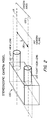
- FIG. 2 is a schematic diagram of a stereoscopic video camera model.
- FIG. 3 is an illustration of a disparity prediction mode for P-pictures in the enhancement layer.
- FIG. 4 is an illustration of an enhancement layer predict mode for B-pictures.
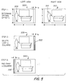
- FIG. 5 illustrates processing of a left-view picture in accordance with the present invention.
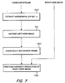
- FIG. 6 illustrates an encoder process flow in accordance with the present invention.
- FIG. 7 illustrates a decoder process flow in accordance with the present invention.
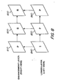
- FIG. 8 illustrates disparity prediction and motion vector searching in accordance with the present invention.
- FIG. 9 illustrates motion vector searching in accordance with the present invention.
- FIG. 10 is a block diagram of an enhancement layer decoder structure in accordance with the present invention.
-
- A method and apparatus are presented for estimating the optimal offset of a scene between right and left channel views in a stereoscopic video system.
- FIG. 1 is a block diagram of a coder/decoder structure for stereoscopic video. The MPEG MVP standard and similar systems involve coding of two video layers, including a lower layer and an enhancement or upper layer. For such an application, the lower layer is assigned to a left view while the enhancement layer is assigned to a right view. In the coder/decoder (e.g., codec) structure of FIG. 1, the lower layer and enhancement layer video sequences are received by a temporal remultiplexer (remux) 105. Using time division multiplexing (TDMX), the enhancement layer video is provided to an
enhancement encoder 110, while the base layer video is provided to alower encoder 115. Note that the lower layer video data may be provided to theenhancement encoder 110 for disparity prediction. - The encoded enhancement and base layers are then provided to a
system multiplexer 120 for transmission to a decoder, shown generally at 122, as a transport stream. The transmission path is typically a satellite link to a cable system headend or directly via satellite to a consumer's home. At thedecoder 122, the transport stream is demultiplexed at asystem demultiplexer 125. The encoded enhancement layer data is provided to anenhancement decoder 130, while the encoded lower layer data is provided to alower decoder 135. Note that decoding is preferably carried out concurrently with the lower and enhancement layers in a parallel processing configuration. Alternatively, theenhancement decoder 130 andlower decoder 135 may share common processing hardware, in which case decoding may be carried out sequentially, one picture at a time. - The decoded lower layer data is output from the
lower decoder 135 as a separate data stream, and is also provided to atemporal remultiplexer 140. At thetemporal remultiplexer 140, the decoded base layer data and the decoded enhancement layer data are combined to provide an enhancement layer output signal as shown. The enhancement and lower layer output signals are then provided to a display device for viewing. - FIG. 2 is a schematic diagram of a stereoscopic video camera model. The camera apparatus, shown generally at 100, includes a
right view lens 120 and aleft view lens 110 withrespective axes axes camera plane 140. Thecamera apparatus 100 includes two identical cameras, each with a respective lens, so that two separate recordings of a scene are obtained. The cameras are oriented with parallel axes and coplanar image sensors, such as charge coupled devices (CCDs). Thus, the displacement (disparity) of two images of a scene at a given moment is mainly horizontal and is created by the horizontal separation of thelenses - A stereoscopic imaging system replicates the principle of human vision system to provide two views of a scene. By presenting the appropriate views on a suitable display to the corresponding left- and right-eyes of a viewer, two slightly different perspective views of the scene are imaged on each retina. The brain then fuses these images into one view, and the viewer experiences the sensation of stereopsis (stereoscopic vision), which provides added realism through improved depth perception.
- To efficiently transmit stereoscopic video data, coding (e.g., compression) of the images of the two views must be efficient. Efficient coding of a stereoscopic video depends not only on motion compensation, but also on disparity (e.g., cross-channel or cross-layer) prediction. By reducing a motion vector search range for disparity prediction between left- and right-view pictures, a low complexity encoder can be implemented. This is achieved by optimally estimating the global location-offset of a scene between pictures of two views at the same temporal reference point.
- The system presented herein may be used a performance enhancement option of the MPEG-2 Multi-View Profile (MVP) and MPEG-4 Video Verification Model (VM) (Version 3.0 and above) experiments for disparity prediction of stereoscopic video coding. MVP (or MPEG-4 MV 3.0) involves two layer coding, namely a lower or base layer and an enhancement layer. For stereoscopic video coding, the lower layer is assigned to the left view and the enhancement layer is assigned to the right view. The disparity estimation/prediction modes of the enhancement layer in MVP for P- and B-pictures consist of a macroblock-based block matching technique. In an MVP decoder, these prediction modes are shown in FIGs 3, 4 and 8.
- With stereoscopic video coding, a horizontal disparity vector for each disparity-predicted macroblock is expected because of the offset of the view points. In fact, this causes inefficient variable length (Huffman) coding (VLC) of these disparity vectors. The present invention addresses the problem of how to determine the horizontal offset of stereoscopic views such that the coding of estimated disparity vectors becomes more efficient.
- In accordance with the present invention, the left-view image is offset by an appropriate number of pixels such that the displacement between the offset left-view image and the right-view image can be reduced. The disparity prediction based on this new image pair is therefore more efficient.
- FIG. 3 is an illustration of a disparity prediction mode for P-pictures in the enhancement layer. Here, a P-
picture 310 in the enhancement layer is disparity predicted using a temporally coincident I-picture 300 in the lower layer. - FIG. 4 is an illustration of an enhancement layer predict mode for B-pictures. Here, a B-
picture 410 in the enhancement layer is predicted using both forward prediction and disparity prediction. Specifically, the B-picture 410 is forward predicted using another B-picture 420, which is the most recent decoded enhancement layer picture, and an I-picture 400, which is the most recent lower layer picture, in display order. - FIG. 5 illustrates processing of a left-view picture in accordance with the present invention. A global horizontal position offset technique of the present invention improves coding efficiency while maintaining compatibility with existing stereoscopic coding standards. The global horizontal position offset method obtains a horizontal position shift of the left-view image such that the distortion between the (shifted) left-view image and the corresponding right-view image is minimized. This technique is applicable to arbitrarily shaped images such as Video Object Planes (VOP) as discussed in the MPEG-4 standard as well as rectangular images, e.g., a video frame or picture or sub-portion thereof as used in the MPEG-2 MVP standard. Specifically, a VOP in a left-view image is shifted to the right by deleting the x leftmost pixels which extend vertically on the VOP, i.e., at the leftmost edge of the VOP, and padding x pixels starting at the rightmost edge of the VOP. Thus, the rightmost edge is extended horizontally by x pixels. The position of the VOP is thus shifted with respect to the left-view frame in which it is situated as well as with respect to the corresponding VOP in the right-view image. Generally, the rightmost and leftmost portions of the left-view frame are unchanged, assuming the VOP does not extend to the vertical boundaries of the frame.
- In FIG. 5, a left-
view image 500 and right-view image 510 are shown. Parameters h and w denote the high and width, respectively, for both images. For example, for NTSC video, h=480 and w=704, and for PAL video, h=576 and w=704). Parameters yL(i,j) and yR(i,j) represent the luminance pixel values of the left- (or lower) and right-view images, respectively. The parameter yR(i,j) may be referred to as yE(i,j) where the subscript "E" denotes the enhancement layer. - The technique is discussed assuming the left-view image is in the lower layer and the right-view image is in the enhancement layer. However, the technique is easily adapted for use in a stereoscopic video system where the right-view image is in the lower layer and the left-view image is in the enhancement layer.
- The left-
view image 500 includes afeature 505, while the right-view image 510 includes thesame feature 515 but in a different relative position within the frame. Specifically, theimage 500 is relatively offset to the left of theimage 510 by a distance x. In a first step, the value x is the horizontal offset which is to be determined, and is assumed to fall within a pre-assigned or pre-determined range X, that is, 0 ≤ x ≤ X. - The global horizontal position offset technique in accordance with a first embodiment of the present invention is to find the horizontal offset integer value x such that:
- In another embodiment of the present invention, the offset value x is found such that:
- In another embodiment of the present invention, a horizontal offset xest is estimated by using a camera focus parameter and the inter-ocular separation δ. For example, an estimated offset of ten pixels (e.g., +/-5) may be used. Then, an exhaustive horizontal search is performed for max{xest-5, 0} ≤ i ≤ { xest+5 } to find the offset x such that Dist_L1(x) or Dist_L2(x) is a minimum.
- A left-view reference frame for disparity estimation and prediction is obtained as follows. After determining the horizontal offset x in the encoder, a reference frame is constructed from the original and reconstructed left-view images for disparity estimation/prediction of the right-view image. If the video standard allows the offset value x to be transmitted to a decoder, the offset x is extracted at the decoder, and the reference frame is reconstructed from the decoded left-view image for disparity prediction/compensation of the right-view image. The offset may be transmitted in the user data portion of a picture header, for example.
- The construction process of the reference frame for luminance pixels is achieved, in a second step, by deleting the last x columns of the left-view image. At the encoder, the original left-view image is used, while at the decoder, the decoded left-view image is used. Referring to the left-view image 535, the last x
columns 520 at the right-hand side of the image 535 are deleted. - In a third step, for each row of the left-
view image 540, fill x pixels in the beginning of the row with the first pixel value of the row. The fill (e.g., padding) process can be accomplished as described in the MPEG-4 standard. The paddedregion 530 is shown at the left-hand side of theimage 540. As a result of the foregoing steps, an offset or shifted left-view image 540 is obtained that more closely matches the corresponding right-view image. - For the chrominance pixel data, the construction process of the reference frame for disparity prediction consists of the same steps given, but with a horizotal offset of
- FIG. 6 illustrates an encoder process flow in accordance with the present invention. The process shown corresponds to the case where the horizontal offset value x can be transmitted to a decoder. For the case where the horizontal offset cannot be transmitted, e.g., with the MPEG-2 MVP standard, the horizontal offset value x can still be used to reduce the complexity of disparity vector searching in the encoder, as discussed in connection with FIGs 8 and 9.
- The offset value x may be determined according to various protocols. For example, x may be computed and stored for each successive image in a video sequence. However, this may be computationally burdensome and unnecessary. Alternatively, the offset x may be determined whenever a scene change is detected, or at the start of a new group of pictures (GOP). A group of pictures (GOP) indicates one or more consecutive pictures which can be decoded without reference to pictures in another GOP. The selection of an optimum criteria for recalculating the offset x should be based on implementation complexity and video characteristics.
- If the offset x is not newly recalculated for the current image, the previous stored offset can be used.
- The left-view image is provided to a
block 610, where it is determined whether a scene change or a new GOP is detected. If so, atblock 620, the offset search range X (where 0 ≤ x ≤ X) is loaded, e.g., into memory for use by a microcomputer. If not, atblock 600, the horizontal offset x which was determined from the last scene is used. - At
block 630, the offset x is determined using either the minimum mean error or the minimum mean squared error discussed previously. The right-view image data is used for this procedure. Atblock 640, the reference frame is constructed using the procedure discussed in connection with FIG. 5. The right-view image data is also used for this procedure. - At
block 650, the newly-constructed reference frame is searched to determine best-match macroblocks. That is, a search range is defined in the reference frame over which each macroblock is compared to a right-view macroblock which is currently being coded to determine the one reference frame macroblock which most closely matches the right-view macroblock which is currently being coded. Since the reference frame is offset relative to the original left-view image, it more closely resembles the right-view image, and a reduced search range may be used to obtain the best match macroblock. For example, as discussed in connection with FIG. 9 below, the search range may be reduced from 64x48 pixels to 8x8 pixels, for example. - At
block 660, the right-view image is encoded using known techniques, such as those disclosed in the MVP standard. Atblock 670, the encoded data and the offset x are transmitted to a decoder, e.g., in a satellite broadcast CATV network, as discussed in connection with FIG. 7. Some video communication standards may not provide for the transmission of the offset value x, in which case the offset can be used only at the encoder to reduce the search range. - FIG. 7 illustrates a decoder process flow in accordance with the present invention. In this case, the offset x is assumed to be transmitted with the video data in a coded bitstream. At
block 700, the horizontal offset is extracted from the coded bitstream. Atblock 710, the left-view image is decoded in a conventional manner. Atblock 720, the reference frame is constructed using the offset x. Atblock 730, the right-view image is disparity predicted using the encoded right-view image data and the reference frame. The offset x and motion vectors are used to identify the best-match macroblocks of the reference frame, and the full right-view image is recovered using the sum of the pixel data of the best-match macroblocks and the differentially encoded right-vew image data. - For cases where the horizontal offset can not be transmitted, e.g. with the MPEG-2 MVP standard, the horizontal offset can still be used to reduce the complexity of the disparity vector search in the encoder, e.g., by reducing the motion vector search range.
- FIG. 8 illustrates disparity prediction and motion vector searching in accordance with the present invention. The enhancement layer includes a P-
picture 810, a B-picture 820, and a B-picture 830, while the lower layer includes an I-picture 840, a P-picture 850 and a P-picture 860. Prediction is indicated by the direction of the arrows such that the arrow points from the reference image to the predicted image. For example, each macroblock in the P-picture 850 is predicted using corresponding best-match macroblocks in the I-picture 840. - For each ith macroblock, a motion vector (vx,vy) indicates the relative displacement of the best-match macroblock to the predicted macroblock. For lower layer prediction, the estimation is centered at a non-offset position of each macroblock. For example, the upper left hand pixel of each predicted macroblock may be taken as the non-offset coordinate (0,0).
- The B-
picture 820 is disparity predicted using the P-picture 850 in the lower layer and temporally predicted using the P-picture 810 in the enhancement layer. For disparity prediction, the horizontal offset x is determined as discussed. Next, macroblocks in the B-picture 820 are disparity predicted by locating best-match macroblocks in the P-picture 850, where the disparity estimation/prediction is centered on (x,0) rather than (0,0). That is, the estimation is shifted by x pixels to the right. - The disparity vector (vx,vy) indicates the positional difference between corresponding macroblocks of pixels of the base layer and the enhancement layer, and is used for reconstruction of the disparity-predicted enhancement layer picture at a decoder. In particular, with the pixel coordinates for a search window macroblock in the enhancement layer being (xs,ys), and the pixel coordinates for a corresponding reference window macroblock in the base layer being (xr,yr), the disparity vector is
- Moreover, the temporal prediction of the B-
picture 820 using the P-picture 810 is centered at (vx,vy) for each ith macroblock. - The disparity prediction and motion vector searching process can be further understood with reference to FIG. 9.
- FIG. 9 illustrates motion vector searching in accordance with the present invention. As discussed in connection with FIG. 8, a vector (vx,vy) defines a
best match macroblock 920 in the I-picture 840 for anith macroblock 900 in the P-picture 850. The vector indicates the amount of temporal movement of an image between the two pictures. Asearch range 910 is used to find thebest match macroblock 920. The search range may have a total size of 82x64 pixels, corresponding to a variation of 64x48 for the16x16 macroblock 900. - For disparity prediction of macroblocks in the B-
picture 820 in the enhancement layer, theith macroblock 930 is centered at (x,0), and is compared to macroblocks in a smaller search range 940, for example, having a total size of 24x24 pixels, corresponding to a variation of 8x8 for a 16x16 macroblock. The offset value x allows a smaller search range to be used since the best-match macroblock for differentially encoding themacroblock 930 is likely to be in a smaller neighborhood of pixels nearmacroblock 930. Accordingly, a faster processing time and reduced memory requirements can be realized. - Additionally, when the offset value is transmitted to the decoders, more efficient variable length coding (e.g., Huffman coding) of disparity vectors results since each disparity vector is smaller, thereby reducing the amount of data which must be transmitted.
- A macroblock in the B-
picture 820 which is co-sited with themacroblock 900 in the P-picture 850 can also use a smaller search range in the P-picture 810 which is centered on themacroblock 920 defined by the vector (vx,vy). For example, the motion vector search range for the right-view sequence can also be reduced as low as an 8x8 variation. This is true since the correlation between the B-picture 820 and the P-picture 810 is likely to be similar to the correlation between the P-picture 850 and the I-picture 840. - FIG. 10 is a block diagram of an enhancement layer decoder structure in accordance with the present invention. The decoder, shown generally at 130, includes an
input terminal 1005 for receiving the compressed enhancement layer data, and a transportlevel syntax parser 1010 for parsing the data. The parsed data is provided to amemory manager 1030, which may comprise a central processing unit. Thememory manager 1030 communicates with amemory 1020, which may comprise a dynamic random-access memory (DRAM), for example. The horizontal offset x may be communicated with the enhancement layer data or otherwise provided in the stereoscopic video signal. A reference frame is constructed using the decoded lower layer data and the offset x. - The
memory manager 1030 also communicates with a decompression/prediction processor 1040, and receives decoded lower level data via terminal 1050 which may be stored temporarily in thememory 1020 for subsequent use by theprocessor 1040 in decoding the disparity-predicted enhancement layer pictures. - The decompression/
prediction processor 1040 provides a variety of processing functions, such as error detection and correction, motion vector decoding, inverse quantization, inverse discrete cosine transformation, Huffman decoding and prediction calculations, for instance. After being processed by the decompression/prediction function 1040, decoded enhancement layer data is output by the memory manager. Alternatively, the decoded data may be output directly from the decompression/prediction function 1040 via means not shown. - An analogous structure may be used for the lower layer. Moreover, the enhancement and lower layer decoders may share common hardware. For example, the
memory 1020 andprocessor 1040 may be shared. - Test results conform that the view offset estimation technique of the present invention can effectively improve coding efficiency for stereoscopic video signals. The offset estimation technique was implemented in a MPEG-2 MVP program and run through the Class D video test sequences of ISO/IEC JTC1/SC29/WG11/MPEG-4 and some other sequences. Examples of test results with an offset search range of X=20 pixels are shown in Table 1. The improvement in coding efficiency over MVP in bits/frame ranges from 2.0 to 5.2%. PSNR indicates the peak signal-to-noise ratio. All picture types are P-pictures.
Sequence Quantization Level Q PSNR Total coded bits Improvement (bits/frame) Right-view bit rate Tunnel : (Offset Values x=2; Frame No. n = 50-th) 26 31 210,818 2% 3 Mbits/sec. Tunnel : (Offset Values x=2; Frame No. n = 50th) 33 30 172,011 4% 2 Mbits/sec. Fun Fair (Offset Values x=8; Frame No. n = 2nd) 26 31 223,939 2.3% 3 Mbits/sec. Fun Fair (Offset Values x=8; Frame No. n = 2nd) 33 30 181,071 5.2% 2 Mbits/sec. - Further coding efficiency improvements can be achieved by using a threshold T to zero the residual macroblock after compensation, or zero some high frequency DCT coefficients.
- As can be seen, the present invention provides a system for estimating the optimal offset x of a scene between right and left channel views at the same temporal reference point. The system reduces the motion vector search range for disparity (i.e., cross-channel or cross-layer) prediction to improve coding efficiency. The offset may be recalculated when there is a scene change or a new group of pictures in the lower layer.
- At an encoder, the optimal offset, x, between the enhancement layer image and the lower layer image is determined according to either a minimum mean error between the enhancement and lower layer images, or a minimum mean squared error between the enhancement and lower layer images. The offset x is bounded by an offset search range X. The x rightmost pixel columns of the lower layer image are deleted, and the x leftmost columns of the lower layer image are padded to effectively shift the lower layer image to the right by x pixels to obtain the reference image for use in disparity predicting the enhancement layer image. For arbitrarily shaped images such as VOPs, a VOP in a left-view image is shifted to the right by deleting the x leftmost pixels which extend vertically on the VOP, and padding x pixels starting at the rightmost edge of the VOP.
- The reference frame is searched to obtain best-match macroblocks, and the right-view data is differentially encoded. At a decoder, the offset value x is recovered if available and used to reconstruct the reference frame for disparity prediction.
- Although the invention has been described in connection with various specific embodiments, those skilled in the art will appreciate that numerous adaptations and modifications may be made thereto without departing from the spirit and scope of the invention as set forth in the claims.
Claims (40)
- A method for predicting an enhancement layer image in an enhancement layer of a stereoscopic video signal using a lower-layer image in a lower layer thereof, comprising the steps of:determining an optimal offset, x, between said enhancement layer image and said lower layer image according to one of (a) a minimum mean error between pixel values of said enhancement layer image and said lower layer image, and (b) a minimum mean squared error between pixel values of said enhancement layer image and said lower layer image; andshifting said lower layer image according to said optimal offset to obtain a reference image for use in disparity predicting the enhancement layer image.
- The method of claim 1, wherein:the enhancement layer image is disparity predicted from said reference image using motion compensation; anda best-match image is obtained in said reference image using a search range which is reduced relative to a search range of said lower layer image without said shifting.
- The method of claim 1 or 2, comprising the further steps of:determining an estimated offset according to at least one of a camera focus parameter and an inter-ocular separation; andsearching within said lower layer image in a range determined by said estimated offset to find said optimal offset.
- The method of one of the preceding claims, comprising the further step of:searching within a horizontal offset range X to find said optimal offset x such that 0 ≤ x ≤ X.
- The method of one of the preceding claims, wherein:said enhancement layer image and said lower layer image comprise a video object plane.
- The method of one of the preceding claims, wherein:said enhancement layer image and said lower layer image are arbitrarily shaped.
- The method of claim 6, wherein said shifting step comprises the steps of:deleting a leftmost edge region of the VOP which has a width of x pixels; andand padding a rightmost edge portion of the VOP to extend the rightmost edge portion by a width of x pixels.
- The method of one of the preceding claims, wherein said shifting step comprises the steps of:deleting x rightmost pixel columns of the lower layer image; andpadding a leftmost portion of the lower layer image with x pixel columns.
- The method of one of the preceding claims, comprising the further steps of:determining a new optimal offset x when a scene change is detected for the lower layer image; andif a scene change is not detected, using an offset from a prior image in said lower layer as said optimal offset x.
- The method of one of the preceding claims, wherein:a new optimal offset x is determined for a new group of pictures in the lower layer.
- The method of one of the preceding claims, comprising the further step of:transmitting said optimal offset x in said stereoscopic video signal for use by a decoder in recreating the reference image.
- The method of one of the preceding claims, wherein:for said minimum mean error, said optimal offset x is determined such that the value
- The method of claim 12, wherein:for said minimum mean error, an optimal offset for chrominance pixel values isx/2
 .
.
- The method of one of claims 1 to 11, wherein:for said minimum mean squared error, said optimal offset x is determined such that the value
- The method of claim 14, wherein:for said minimum mean squared error, an optimal offset for chrominance pixel values is
- An apparatus for predicting an enhancement layer image in an enhancement layer of a stereoscopic video signal using a lower layer image in a lower layer thereof, comprising:means for determining an optimal offset, x, between said enhancement layer image and said lower layer image according to one of (a) a minimum mean error between pixel values of said enhancement layer image and said lower layer image, and (b) a minimum mean squared error between pixel values of said enhancement layer image and said lower layer image; andmeans for shifting said lower layer image according to said optimal offset to obtain a reference image for use in disparity predicting the enhancement layer image.
- The apparatus of claim 16, wherein:the enhancement layer image is disparity predicted from said reference image using motion compensation; anda best-match image is obtained in said reference image using a search range which is reduced relative to a search range of said lower layer image without said shifting.
- The apparatus of claim 16 or 17, further comprising:means for determining an estimated offset according to at least one of a camera focus parameter and an inter-ocular separation; andmeans for searching within said lower layer image in a range determined by said estimated offset to find said optimal offset.
- The apparatus of one of claims 16 to 18, further comprising:means for searching within a horizontal offset range X to find said optimal offset x such that 0 ≤ x ≤ X.
- The apparatus of one of claims 16 to 19, wherein:said enhancement layer image and said lower layer image comprise a video object plane.
- The apparatus of one of claims 16 to 20, wherein:said enhancement layer image and said lower layer image are arbitrarily shaped.
- The apparatus of claim 21, wherein said means for shifting deletes a leftmost edge region of the VOP which has a width of x pixels, and pads a rightmost edge portion of the VOP to extend the rightmost edge portion by a width of x pixels.
- The apparatus of one of claims 16 to 22, wherein said means for shifting deletes x rightmost pixel columns of the lower layer image, and pads a leftmost portion of the lower layer image with x pixel columns.
- The apparatus of one of claims 16 to 23, further comprising means for:(a) determining a new optimal offset x when a scene change is detected for the lower layer image; and(b) if a scene change is not detected, using an offset from a prior image in said lower layer as said optimal offset x.
- The apparatus of one of claims 16 to 24, wherein:a new optimal offset x is determined for a new group of pictures in the lower layer.
- The apparatus of one of claims 16 to 25, further comprising:means for transmitting said optimal offset x in said stereoscopic video signal for use by a decoder in recreating the reference image.
- The apparatus of claim 16, wherein:for said minimum mean error, said optimal offset x is determined such that the value
- The apparatus of claim 27, wherein:for said minimum mean error, an optimal offset for chrominance pixel values is
- The apparatus of one of claims 16 to 25, wherein:for said minimum mean squared error, said optimal offset x is determined such that the value
- The apparatus of claim 29, wherein:for said minimum mean squared error, an optimal offset for chrominance pixel values is
- A decoder for predicting an enhancement layer image in an enhancement layer of a stereoscopic video signal using a lower layer image in a lower layer thereof, comprising:means for recovering an optimal offset, x, between said enhancement layer image and said lower layer image from said stereoscopic video signal;said optimal offset x being determined at an encoder according to one of (a) a minimum mean error between pixel values of said enhancement layer image and said lower layer image, and (b) a minimum mean squared error between pixel values of said enhancement layer image and said lower layer image; andmeans for shifting said lower layer image according to said optimal offset to obtain a reference image for use in disparity predicting the enhancement layer image.
- The decoder of claim 31, wherein:the enhancement layer image is disparity predicted from said reference image using motion compensation; anda best-match image is obtained in said reference image using a search range which is reduced relative to a search range of said lower layer image without said shifting.
- The decoder of claim 31 or 32, wherein:said enhancement layer image and said lower layer image comprise a video object plane.
- The decoder of one of claims 31 to 33, wherein:said enhancement layer image and said lower layer image are arbitrarily shaped.
- The decoder of claim 34, wherein said means for shifting deletes a leftmost edge region of the VOP which has a width of x pixels, and pads a rightmost edge portion of the VOP to extend the rightmost edge portion by a width of x pixels.
- The decoder of one of claims 31 to 35, wherein said means for shifting deletes x rightmost pixel columns of the lower layer image, and pads a leftmost portion of the lower layer image with x pixel columns.
- The decoder of one of claims 31 to 36, wherein:for said minimum mean error, said optimal offset x is determined such that the value
- The decoder of claim 37, wherein:for said minimum mean error, an optimal offset for chrominance pixel values is
- The decoder of one of claims 31 to 36, wherein:for said minimum mean squared error, said optimal offset x is determined such that the value
- The decoder of claim 39, wherein:for said minimum mean squared error, an optimal offset for chrominance pixel values is
Applications Claiming Priority (2)
| Application Number | Priority Date | Filing Date | Title |
|---|---|---|---|
| US966277 | 1997-11-07 | ||
| US08/966,277 US6043838A (en) | 1997-11-07 | 1997-11-07 | View offset estimation for stereoscopic video coding |
Publications (3)
| Publication Number | Publication Date |
|---|---|
| EP0915433A2 true EP0915433A2 (en) | 1999-05-12 |
| EP0915433A3 EP0915433A3 (en) | 2000-02-23 |
| EP0915433B1 EP0915433B1 (en) | 2005-04-27 |
Family
ID=25511147
Family Applications (1)
| Application Number | Title | Priority Date | Filing Date |
|---|---|---|---|
| EP98120697A Expired - Lifetime EP0915433B1 (en) | 1997-11-07 | 1998-11-06 | View offset estimation for steroscopic video coding |
Country Status (9)
| Country | Link |
|---|---|
| US (1) | US6043838A (en) |
| EP (1) | EP0915433B1 (en) |
| JP (1) | JPH11262032A (en) |
| KR (1) | KR19990045067A (en) |
| CN (1) | CN1226786A (en) |
| CA (1) | CA2252324C (en) |
| DE (1) | DE69829931T2 (en) |
| NO (1) | NO985170L (en) |
| TW (1) | TW426835B (en) |
Cited By (8)
| Publication number | Priority date | Publication date | Assignee | Title |
|---|---|---|---|---|
| WO2000013142A1 (en) * | 1998-08-28 | 2000-03-09 | Sarnoff Corporation | Method and apparatus for processing images |
| EP1185112A2 (en) * | 2000-08-25 | 2002-03-06 | Fuji Photo Film Co., Ltd. | Apparatus for parallax image capturing and parallax image processing |
| EP1418766A2 (en) * | 1998-08-28 | 2004-05-12 | Imax Corporation | Method and apparatus for processing images |
| EP1889490A1 (en) * | 2005-05-31 | 2008-02-20 | Samsung Electronics Co, Ltd | Multi-view image system and method for compressing and decompressing applied to the same |
| WO2012112142A1 (en) * | 2011-02-15 | 2012-08-23 | Thomson Licensing | Apparatus and method for generating a disparity map in a receiving device |
| WO2014130489A1 (en) * | 2013-02-23 | 2014-08-28 | Microsoft Corporation | Real time stereo matching |
| US9098908B2 (en) | 2011-10-21 | 2015-08-04 | Microsoft Technology Licensing, Llc | Generating a depth map |
| US9402086B2 (en) | 2010-04-09 | 2016-07-26 | Thomson Licensing | Method for processing stereoscopic images and corresponding device |
Families Citing this family (85)
| Publication number | Priority date | Publication date | Assignee | Title |
|---|---|---|---|---|
| US6351563B1 (en) * | 1997-07-09 | 2002-02-26 | Hyundai Electronics Ind. Co., Ltd. | Apparatus and method for coding/decoding scalable shape binary image using mode of lower and current layers |
| JP4056154B2 (en) * | 1997-12-30 | 2008-03-05 | 三星電子株式会社 | 2D continuous video 3D video conversion apparatus and method, and 3D video post-processing method |
| KR100334722B1 (en) * | 1999-06-05 | 2002-05-04 | 강호석 | Method and the apparatus for generating stereoscopic image using MPEG data |
| EP1243141B1 (en) * | 1999-12-14 | 2011-10-19 | Scientific-Atlanta, LLC | System and method for adaptive decoding of a video signal with coordinated resource allocation |
| KR100830355B1 (en) * | 2000-03-31 | 2008-05-20 | 코닌클리케 필립스 일렉트로닉스 엔.브이. | Method, encoder, decoder, and multiplex for the encoding and decoding of two correlated sequences of data |
| US6493387B1 (en) * | 2000-04-10 | 2002-12-10 | Samsung Electronics Co., Ltd. | Moving picture coding/decoding method and apparatus having spatially scalable architecture and signal-to-noise ratio scalable architecture together |
| JP2002010251A (en) * | 2000-06-19 | 2002-01-11 | Matsushita Electric Ind Co Ltd | Video signal coding device and video signal decoding device |
| JP2004515132A (en) * | 2000-11-23 | 2004-05-20 | コーニンクレッカ フィリップス エレクトロニクス エヌ ヴィ | Video encoding method and corresponding encoder |
| JP2004531925A (en) * | 2001-03-05 | 2004-10-14 | インタービデオインコーポレイテッド | System and method for encoding and decoding redundant motion vectors in a compressed video bitstream |
| US6925120B2 (en) * | 2001-09-24 | 2005-08-02 | Mitsubishi Electric Research Labs, Inc. | Transcoder for scalable multi-layer constant quality video bitstreams |
| US7274857B2 (en) * | 2001-12-31 | 2007-09-25 | Scientific-Atlanta, Inc. | Trick modes for compressed video streams |
| US7319720B2 (en) * | 2002-01-28 | 2008-01-15 | Microsoft Corporation | Stereoscopic video |
| CA2380105A1 (en) * | 2002-04-09 | 2003-10-09 | Nicholas Routhier | Process and system for encoding and playback of stereoscopic video sequences |
| US7391807B2 (en) * | 2002-04-24 | 2008-06-24 | Mitsubishi Electric Research Laboratories, Inc. | Video transcoding of scalable multi-layer videos to single layer video |
| US7454123B2 (en) * | 2002-06-06 | 2008-11-18 | Intel Corporation | Personal video recorder having reduced overscan coding |
| EP1527613B1 (en) * | 2002-07-31 | 2014-09-10 | Koninklijke Philips N.V. | Method and apparatus for encoding a digital video signal |
| KR100565791B1 (en) * | 2003-08-04 | 2006-03-29 | 삼성전자주식회사 | Apparatus and Method for presumption motion vector |
| US7778328B2 (en) | 2003-08-07 | 2010-08-17 | Sony Corporation | Semantics-based motion estimation for multi-view video coding |
| US7966642B2 (en) * | 2003-09-15 | 2011-06-21 | Nair Ajith N | Resource-adaptive management of video storage |
| US20050100098A1 (en) * | 2003-10-23 | 2005-05-12 | Gong-Sheng Lin | Highly integrated mpeg-4 video decoding unit |
| EP1727090A1 (en) * | 2004-02-27 | 2006-11-29 | Tdvision Corporation S.A. DE C.V. | Method and system for digital decoding 3d stereoscopic video images |
| CN1926576A (en) * | 2004-02-27 | 2007-03-07 | Td视觉有限公司 | Method and system for digital coding three-dimensional video image |
| US8600217B2 (en) * | 2004-07-14 | 2013-12-03 | Arturo A. Rodriguez | System and method for improving quality of displayed picture during trick modes |
| KR100688383B1 (en) * | 2004-08-13 | 2007-03-02 | 경희대학교 산학협력단 | Motion estimation and compensation for panorama image |
| US7623682B2 (en) * | 2004-08-13 | 2009-11-24 | Samsung Electronics Co., Ltd. | Method and device for motion estimation and compensation for panorama image |
| TWI268715B (en) * | 2004-08-16 | 2006-12-11 | Nippon Telegraph & Telephone | Picture encoding method, picture decoding method, picture encoding apparatus, and picture decoding apparatus |
| WO2006080739A1 (en) * | 2004-10-12 | 2006-08-03 | Electronics And Telecommunications Research Institute | Method and apparatus for encoding and decoding multi-view video using image stitching |
| WO2007004633A1 (en) * | 2005-07-05 | 2007-01-11 | Sanyo Electric Co., Ltd. | 3-d image processing method and 3-d image processing device and program and program-stored recording medium |
| KR100762783B1 (en) * | 2005-07-11 | 2007-10-05 | (주)블루비스 | Apparatus for encoding and decoding multi-view image |
| US8644386B2 (en) * | 2005-09-22 | 2014-02-04 | Samsung Electronics Co., Ltd. | Method of estimating disparity vector, and method and apparatus for encoding and decoding multi-view moving picture using the disparity vector estimation method |
| US8902977B2 (en) * | 2006-01-09 | 2014-12-02 | Thomson Licensing | Method and apparatus for providing reduced resolution update mode for multi-view video coding |
| US8456515B2 (en) * | 2006-07-25 | 2013-06-04 | Qualcomm Incorporated | Stereo image and video directional mapping of offset |
| CN101166271B (en) * | 2006-10-16 | 2010-12-08 | 华为技术有限公司 | A visual point difference estimate/compensation method in multi-visual point video coding |
| US20100266042A1 (en) * | 2007-03-02 | 2010-10-21 | Han Suh Koo | Method and an apparatus for decoding/encoding a video signal |
| US8155461B2 (en) * | 2007-03-27 | 2012-04-10 | Samsung Electronics Co., Ltd. | Methods and apparatuses for encoding and decoding multi-view image |
| WO2008133455A1 (en) * | 2007-04-25 | 2008-11-06 | Lg Electronics Inc. | A method and an apparatus for decoding/encoding a video signal |
| WO2008140190A1 (en) * | 2007-05-14 | 2008-11-20 | Samsung Electronics Co, . Ltd. | Method and apparatus for encoding and decoding multi-view image |
| KR101381601B1 (en) * | 2007-05-14 | 2014-04-15 | 삼성전자주식회사 | Method and apparatus for encoding and decoding multi-view image |
| US20090033791A1 (en) * | 2007-07-31 | 2009-02-05 | Scientific-Atlanta, Inc. | Video processing systems and methods |
| MX2011000728A (en) * | 2008-07-21 | 2011-03-29 | Thomson Licensing | Multistandard coding device for 3d video signals. |
| US8300696B2 (en) * | 2008-07-25 | 2012-10-30 | Cisco Technology, Inc. | Transcoding for systems operating under plural video coding specifications |
| US8300089B2 (en) | 2008-08-14 | 2012-10-30 | Reald Inc. | Stereoscopic depth mapping |
| US9251621B2 (en) * | 2008-08-14 | 2016-02-02 | Reald Inc. | Point reposition depth mapping |
| JP5202190B2 (en) * | 2008-08-28 | 2013-06-05 | キヤノン株式会社 | Image processing method and image processing apparatus |
| US8610726B2 (en) * | 2008-09-26 | 2013-12-17 | Apple Inc. | Computer systems and methods with projected display |
| US7881603B2 (en) | 2008-09-26 | 2011-02-01 | Apple Inc. | Dichroic aperture for electronic imaging device |
| US20100079653A1 (en) * | 2008-09-26 | 2010-04-01 | Apple Inc. | Portable computing system with a secondary image output |
| WO2010038365A1 (en) * | 2008-09-30 | 2010-04-08 | パナソニック株式会社 | Recording medium, reproduction device, system lsi, reproduction method, spectacle, and display device associated with 3d video |
| EP2340534B1 (en) * | 2008-10-03 | 2013-07-24 | RealD Inc. | Optimal depth mapping |
| KR20100089705A (en) * | 2009-02-04 | 2010-08-12 | 삼성전자주식회사 | Apparatus and method for encoding and decoding 3d video |
| US8428122B2 (en) * | 2009-09-16 | 2013-04-23 | Broadcom Corporation | Method and system for frame buffer compression and memory resource reduction for 3D video |
| JP4875127B2 (en) | 2009-09-28 | 2012-02-15 | パナソニック株式会社 | 3D image processing device |
| US8619128B2 (en) * | 2009-09-30 | 2013-12-31 | Apple Inc. | Systems and methods for an imaging system using multiple image sensors |
| US9602814B2 (en) | 2010-01-22 | 2017-03-21 | Thomson Licensing | Methods and apparatus for sampling-based super resolution video encoding and decoding |
| WO2011090798A1 (en) | 2010-01-22 | 2011-07-28 | Thomson Licensing | Data pruning for video compression using example-based super-resolution |
| US8878913B2 (en) * | 2010-03-12 | 2014-11-04 | Sony Corporation | Extended command stream for closed caption disparity |
| WO2012033972A1 (en) | 2010-09-10 | 2012-03-15 | Thomson Licensing | Methods and apparatus for pruning decision optimization in example-based data pruning compression |
| CN103141092B (en) * | 2010-09-10 | 2016-11-16 | 汤姆逊许可公司 | The method and apparatus carrying out encoded video signal for the super-resolution based on example of video compress use motion compensation |
| KR101640404B1 (en) * | 2010-09-20 | 2016-07-18 | 엘지전자 주식회사 | Mobile terminal and operation control method thereof |
| US8538132B2 (en) | 2010-09-24 | 2013-09-17 | Apple Inc. | Component concentricity |
| LU91745B1 (en) * | 2010-10-15 | 2012-04-16 | Iee Sarl | Range image pixel matching method |
| JP2014500674A (en) * | 2010-12-08 | 2014-01-09 | トムソン ライセンシング | Method and system for 3D display with adaptive binocular differences |
| EP2667614A4 (en) * | 2011-01-21 | 2013-11-27 | Panasonic Corp | Motion picture coding device and motion picture coding method |
| KR101763944B1 (en) * | 2011-02-18 | 2017-08-01 | 엘지디스플레이 주식회사 | Image display device |
| JP2012257198A (en) * | 2011-05-17 | 2012-12-27 | Canon Inc | Stereoscopic image encoding apparatus, method therefor, and image pickup apparatus having stereoscopic image encoding apparatus |
| US9485518B2 (en) | 2011-05-27 | 2016-11-01 | Sun Patent Trust | Decoding method and apparatus with candidate motion vectors |
| EP3614665B1 (en) * | 2011-05-27 | 2022-03-23 | Sun Patent Trust | Apparatus, method and program for decoding moving pictures |
| TW201304552A (en) | 2011-05-31 | 2013-01-16 | Panasonic Corp | Moving picture coding method, moving picture coding apparatus, moving picture decoding method, moving picture decoding apparatus, and moving picture coding and decoding apparatus |
| CN105049864A (en) | 2011-06-28 | 2015-11-11 | 三星电子株式会社 | Video encoding method using offset adjustments according to pixel classification and apparatus therefor |
| IN2014CN00729A (en) | 2011-08-03 | 2015-04-03 | Panasonic Corp | |
| TWI456975B (en) | 2011-08-23 | 2014-10-11 | Acer Inc | Devices and methods for 3-d image processing |
| CN102984538B (en) * | 2011-09-05 | 2015-02-25 | 宏碁股份有限公司 | Device and method for three-dimensional image processing |
| CN102984548B (en) * | 2011-09-05 | 2014-12-31 | 中国移动通信集团公司 | 3D video coding transmission method and apparatus |
| CN108881903B (en) | 2011-10-19 | 2022-01-04 | 太阳专利托管公司 | Image encoding method and device, image decoding method and device, and encoding and decoding device |
| TWI461066B (en) * | 2011-11-03 | 2014-11-11 | Ind Tech Res Inst | Motion estimation method and disparity estimation method for adaptive search range |
| WO2013109112A1 (en) * | 2012-01-19 | 2013-07-25 | 삼성전자 주식회사 | Multi-view video prediction method for view conversion and apparatus therefor, multi-view video prediction restoring method for viewpoint conversion and apparatus therefor |
| WO2014000154A1 (en) * | 2012-06-26 | 2014-01-03 | Intel Corporation | Cross-layer cross-channel sample prediction |
| WO2014000168A1 (en) * | 2012-06-27 | 2014-01-03 | Intel Corporation | Cross-layer cross-channel residual prediction |
| KR20140080884A (en) * | 2012-12-20 | 2014-07-01 | 주식회사 팬택 | Method for decoding intra prediction mode of chroma block on scalable video coding and apparatus for using the same |
| US9998750B2 (en) | 2013-03-15 | 2018-06-12 | Cisco Technology, Inc. | Systems and methods for guided conversion of video from a first to a second compression format |
| CA2909550C (en) * | 2013-07-15 | 2018-04-24 | Mediatek Singapore Pte. Ltd. | Method of disparity derived depth coding in 3d video coding |
| US9356061B2 (en) | 2013-08-05 | 2016-05-31 | Apple Inc. | Image sensor with buried light shield and vertical gate |
| US9537779B2 (en) * | 2013-10-11 | 2017-01-03 | Huawei Technologies Co., Ltd. | System and method for real-time traffic delivery |
| CN105215098B (en) * | 2015-10-27 | 2017-10-13 | 安徽哈科数控机床制造有限公司 | A kind of bender and its application method |
| CN117917077A (en) * | 2021-08-19 | 2024-04-19 | 联发科技股份有限公司 | Method and apparatus for hardware friendly template matching in video codec systems |
Citations (2)
| Publication number | Priority date | Publication date | Assignee | Title |
|---|---|---|---|---|
| US5619256A (en) * | 1995-05-26 | 1997-04-08 | Lucent Technologies Inc. | Digital 3D/stereoscopic video compression technique utilizing disparity and motion compensated predictions |
| US5652616A (en) * | 1996-08-06 | 1997-07-29 | General Instrument Corporation Of Delaware | Optimal disparity estimation for stereoscopic video coding |
Family Cites Families (2)
| Publication number | Priority date | Publication date | Assignee | Title |
|---|---|---|---|---|
| US5612735A (en) * | 1995-05-26 | 1997-03-18 | Luncent Technologies Inc. | Digital 3D/stereoscopic video compression technique utilizing two disparity estimates |
| US5886736A (en) * | 1996-10-24 | 1999-03-23 | General Instrument Corporation | Synchronization of a stereoscopic video sequence |
-
1997
- 1997-11-07 US US08/966,277 patent/US6043838A/en not_active Expired - Lifetime
-
1998
- 1998-10-29 TW TW087117979A patent/TW426835B/en not_active IP Right Cessation
- 1998-11-03 CA CA002252324A patent/CA2252324C/en not_active Expired - Fee Related
- 1998-11-05 NO NO985170A patent/NO985170L/en not_active Application Discontinuation
- 1998-11-06 DE DE69829931T patent/DE69829931T2/en not_active Expired - Lifetime
- 1998-11-06 JP JP10316119A patent/JPH11262032A/en active Pending
- 1998-11-06 KR KR1019980047444A patent/KR19990045067A/en not_active IP Right Cessation
- 1998-11-06 EP EP98120697A patent/EP0915433B1/en not_active Expired - Lifetime
- 1998-11-09 CN CN98125816A patent/CN1226786A/en active Pending
Patent Citations (2)
| Publication number | Priority date | Publication date | Assignee | Title |
|---|---|---|---|---|
| US5619256A (en) * | 1995-05-26 | 1997-04-08 | Lucent Technologies Inc. | Digital 3D/stereoscopic video compression technique utilizing disparity and motion compensated predictions |
| US5652616A (en) * | 1996-08-06 | 1997-07-29 | General Instrument Corporation Of Delaware | Optimal disparity estimation for stereoscopic video coding |
Non-Patent Citations (1)
| Title |
|---|
| PURI A ET AL: "BASICS OF STEROSCOPIC VIDEO, NEW COMPRESSION RESULTS WITH MPEG-2 AND A PROPOSAL FOR MPEG-4" SIGNAL PROCESSING. IMAGE COMMUNICATION,NL,ELSEVIER SCIENCE PUBLISHERS, AMSTERDAM, vol. 10, no. 1/03, page 201-233 XP000691766 ISSN: 0923-5965 * |
Cited By (14)
| Publication number | Priority date | Publication date | Assignee | Title |
|---|---|---|---|---|
| EP1418766A2 (en) * | 1998-08-28 | 2004-05-12 | Imax Corporation | Method and apparatus for processing images |
| US6269175B1 (en) | 1998-08-28 | 2001-07-31 | Sarnoff Corporation | Method and apparatus for enhancing regions of aligned images using flow estimation |
| WO2000013142A1 (en) * | 1998-08-28 | 2000-03-09 | Sarnoff Corporation | Method and apparatus for processing images |
| US6490364B2 (en) * | 1998-08-28 | 2002-12-03 | Sarnoff Corporation | Apparatus for enhancing images using flow estimation |
| US7200261B2 (en) | 2000-08-25 | 2007-04-03 | Fujifilm Corporation | Parallax image capturing apparatus and parallax image processing apparatus |
| EP1185112A3 (en) * | 2000-08-25 | 2004-12-08 | Fuji Photo Film Co., Ltd. | Apparatus for parallax image capturing and parallax image processing |
| EP1185112A2 (en) * | 2000-08-25 | 2002-03-06 | Fuji Photo Film Co., Ltd. | Apparatus for parallax image capturing and parallax image processing |
| EP1889490A1 (en) * | 2005-05-31 | 2008-02-20 | Samsung Electronics Co, Ltd | Multi-view image system and method for compressing and decompressing applied to the same |
| EP1889490A4 (en) * | 2005-05-31 | 2013-11-20 | Samsung Electronics Co Ltd | Multi-view image system and method for compressing and decompressing applied to the same |
| US9402086B2 (en) | 2010-04-09 | 2016-07-26 | Thomson Licensing | Method for processing stereoscopic images and corresponding device |
| WO2012112142A1 (en) * | 2011-02-15 | 2012-08-23 | Thomson Licensing | Apparatus and method for generating a disparity map in a receiving device |
| US9628769B2 (en) | 2011-02-15 | 2017-04-18 | Thomson Licensing Dtv | Apparatus and method for generating a disparity map in a receiving device |
| US9098908B2 (en) | 2011-10-21 | 2015-08-04 | Microsoft Technology Licensing, Llc | Generating a depth map |
| WO2014130489A1 (en) * | 2013-02-23 | 2014-08-28 | Microsoft Corporation | Real time stereo matching |
Also Published As
| Publication number | Publication date |
|---|---|
| CA2252324A1 (en) | 1999-05-07 |
| TW426835B (en) | 2001-03-21 |
| DE69829931T2 (en) | 2006-02-23 |
| NO985170L (en) | 1999-05-10 |
| KR19990045067A (en) | 1999-06-25 |
| EP0915433B1 (en) | 2005-04-27 |
| EP0915433A3 (en) | 2000-02-23 |
| US6043838A (en) | 2000-03-28 |
| JPH11262032A (en) | 1999-09-24 |
| CA2252324C (en) | 2005-09-27 |
| NO985170D0 (en) | 1998-11-05 |
| CN1226786A (en) | 1999-08-25 |
| MX9809262A (en) | 2007-02-27 |
| DE69829931D1 (en) | 2005-06-02 |
Similar Documents
| Publication | Publication Date | Title |
|---|---|---|
| EP0915433B1 (en) | View offset estimation for steroscopic video coding | |
| EP0838959B1 (en) | Synchronization of a stereoscopic video sequence | |
| EP0823826B1 (en) | Optimal disparity estimation for stereoscopic video coding | |
| EP0817493B1 (en) | Rate control for stereoscopic digital video encoding | |
| US5619256A (en) | Digital 3D/stereoscopic video compression technique utilizing disparity and motion compensated predictions | |
| US5612735A (en) | Digital 3D/stereoscopic video compression technique utilizing two disparity estimates | |
| US8204133B2 (en) | Method and apparatus for encoding and decoding multi-view video using image stitching | |
| EP0883300B1 (en) | Temporal and spatial scaleable coding for video object planes | |
| US6111596A (en) | Gain and offset correction for efficient stereoscopic coding and improved display | |
| US20070104276A1 (en) | Method and apparatus for encoding multiview video | |
| US20070064800A1 (en) | Method of estimating disparity vector, and method and apparatus for encoding and decoding multi-view moving picture using the disparity vector estimation method | |
| US20070041443A1 (en) | Method and apparatus for encoding multiview video | |
| WO2007035054A1 (en) | Method of estimating disparity vector, and method and apparatus for encoding and decoding multi-view moving picture using the disparity vector estimation method | |
| WO2007024072A1 (en) | Method and apparatus for encoding multiview video | |
| Yang et al. | An MPEG-4-compatible stereoscopic/multiview video coding scheme | |
| Chen et al. | MPEG-2 multiview profile and its application in 3D TV | |
| MXPA98009262A (en) | View offset estimation for stereoscopic video coding | |
| Cho et al. | Stereoscopic video codec for 3D video service over T-DMB | |
| Yang et al. | MPEG-4 based stereoscopic and multiview video coding | |
| Pourazad et al. | An efficient low random-access delay panorama-based multiview video coding scheme | |
| El-Shafai et al. | Computer and Information Sciences | |
| Lim et al. | Motion/disparity compensated multiview sequence coding | |
| MXPA97005999A (en) | Optimal disparity estimation for stereoscopic video coding |
Legal Events
| Date | Code | Title | Description |
|---|---|---|---|
| PUAI | Public reference made under article 153(3) epc to a published international application that has entered the european phase |
Free format text: ORIGINAL CODE: 0009012 |
|
| AK | Designated contracting states |
Kind code of ref document: A2 Designated state(s): DE FR GB NL |
|
| AX | Request for extension of the european patent |
Free format text: AL;LT;LV;MK;RO;SI |
|
| PUAL | Search report despatched |
Free format text: ORIGINAL CODE: 0009013 |
|
| AK | Designated contracting states |
Kind code of ref document: A3 Designated state(s): AT BE CH CY DE DK ES FI FR GB GR IE IT LI LU MC NL PT SE |
|
| AX | Request for extension of the european patent |
Free format text: AL;LT;LV;MK;RO;SI |
|
| 17P | Request for examination filed |
Effective date: 20000715 |
|
| AKX | Designation fees paid |
Free format text: DE FR GB NL |
|
| PGFP | Annual fee paid to national office [announced via postgrant information from national office to epo] |
Ref country code: DK Payment date: 20010919 Year of fee payment: 4 |
|
| 17Q | First examination report despatched |
Effective date: 20040310 |
|
| GRAP | Despatch of communication of intention to grant a patent |
Free format text: ORIGINAL CODE: EPIDOSNIGR1 |
|
| GRAS | Grant fee paid |
Free format text: ORIGINAL CODE: EPIDOSNIGR3 |
|
| GRAA | (expected) grant |
Free format text: ORIGINAL CODE: 0009210 |
|
| AK | Designated contracting states |
Kind code of ref document: B1 Designated state(s): DE FR GB NL |
|
| PG25 | Lapsed in a contracting state [announced via postgrant information from national office to epo] |
Ref country code: NL Free format text: LAPSE BECAUSE OF FAILURE TO SUBMIT A TRANSLATION OF THE DESCRIPTION OR TO PAY THE FEE WITHIN THE PRESCRIBED TIME-LIMIT Effective date: 20050427 |
|
| REG | Reference to a national code |
Ref country code: GB Ref legal event code: FG4D |
|
| REF | Corresponds to: |
Ref document number: 69829931 Country of ref document: DE Date of ref document: 20050602 Kind code of ref document: P |
|
| NLV1 | Nl: lapsed or annulled due to failure to fulfill the requirements of art. 29p and 29m of the patents act | ||
| PLBE | No opposition filed within time limit |
Free format text: ORIGINAL CODE: 0009261 |
|
| STAA | Information on the status of an ep patent application or granted ep patent |
Free format text: STATUS: NO OPPOSITION FILED WITHIN TIME LIMIT |
|
| ET | Fr: translation filed | ||
| 26N | No opposition filed |
Effective date: 20060130 |
|
| REG | Reference to a national code |
Ref country code: DE Ref legal event code: R082 Ref document number: 69829931 Country of ref document: DE Representative=s name: HOEGER, STELLRECHT & PARTNER PATENTANWAELTE, DE |
|
| REG | Reference to a national code |
Ref country code: DE Ref legal event code: R082 Ref document number: 69829931 Country of ref document: DE Representative=s name: BETTEN & RESCH PATENT- UND RECHTSANWAELTE PART, DE Effective date: 20130816 Ref country code: DE Ref legal event code: R082 Ref document number: 69829931 Country of ref document: DE Representative=s name: HOEGER, STELLRECHT & PARTNER PATENTANWAELTE MB, DE Effective date: 20130816 Ref country code: DE Ref legal event code: R082 Ref document number: 69829931 Country of ref document: DE Representative=s name: HOEGER, STELLRECHT & PARTNER PATENTANWAELTE, DE Effective date: 20130816 Ref country code: DE Ref legal event code: R081 Ref document number: 69829931 Country of ref document: DE Owner name: GOOGLE TECHNOLOGY HOLDINGS LLC, MOUNTAIN VIEW, US Free format text: FORMER OWNER: GENERAL INSTRUMENT CORPORATION, HORSHAM, PA., US Effective date: 20130816 Ref country code: DE Ref legal event code: R081 Ref document number: 69829931 Country of ref document: DE Owner name: MOTOROLA MOBILITY LLC (N.D.GES.D. STAATES DELA, US Free format text: FORMER OWNER: GENERAL INSTRUMENT CORPORATION, HORSHAM, PA., US Effective date: 20130816 Ref country code: DE Ref legal event code: R081 Ref document number: 69829931 Country of ref document: DE Owner name: MOTOROLA MOBILITY LLC (N.D.GES.D. STAATES DELA, US Free format text: FORMER OWNER: GENERAL INSTRUMENT CORPORATION, HORSHAM, US Effective date: 20130816 |
|
| REG | Reference to a national code |
Ref country code: GB Ref legal event code: 732E Free format text: REGISTERED BETWEEN 20130919 AND 20130925 |
|
| REG | Reference to a national code |
Ref country code: FR Ref legal event code: TP Owner name: MOTOROLA MOBILITY LLC, US Effective date: 20131230 |
|
| REG | Reference to a national code |
Ref country code: DE Ref legal event code: R082 Ref document number: 69829931 Country of ref document: DE Representative=s name: BETTEN & RESCH PATENT- UND RECHTSANWAELTE PART, DE Ref country code: DE Ref legal event code: R082 Ref document number: 69829931 Country of ref document: DE Representative=s name: HOEGER, STELLRECHT & PARTNER PATENTANWAELTE MB, DE |
|
| REG | Reference to a national code |
Ref country code: FR Ref legal event code: PLFP Year of fee payment: 18 |
|
| REG | Reference to a national code |
Ref country code: FR Ref legal event code: PLFP Year of fee payment: 19 |
|
| PGFP | Annual fee paid to national office [announced via postgrant information from national office to epo] |
Ref country code: GB Payment date: 20161128 Year of fee payment: 19 Ref country code: FR Payment date: 20161123 Year of fee payment: 19 Ref country code: DE Payment date: 20161123 Year of fee payment: 19 |
|
| REG | Reference to a national code |
Ref country code: GB Ref legal event code: 732E Free format text: REGISTERED BETWEEN 20170831 AND 20170906 |
|
| REG | Reference to a national code |
Ref country code: FR Ref legal event code: TP Owner name: GOOGLE TECHNOLOGY HOLDINGS LLC, US Effective date: 20171214 |
|
| REG | Reference to a national code |
Ref country code: DE Ref legal event code: R119 Ref document number: 69829931 Country of ref document: DE |
|
| REG | Reference to a national code |
Ref country code: DE Ref legal event code: R082 Ref document number: 69829931 Country of ref document: DE Representative=s name: BETTEN & RESCH PATENT- UND RECHTSANWAELTE PART, DE Ref country code: DE Ref legal event code: R081 Ref document number: 69829931 Country of ref document: DE Owner name: GOOGLE TECHNOLOGY HOLDINGS LLC, MOUNTAIN VIEW, US Free format text: FORMER OWNER: MOTOROLA MOBILITY LLC (N.D.GES.D. STAATES DELAWARE), LIBERTYVILLE, ILL., US |
|
| GBPC | Gb: european patent ceased through non-payment of renewal fee |
Effective date: 20171106 |
|
| REG | Reference to a national code |
Ref country code: FR Ref legal event code: ST Effective date: 20180731 |
|
| PG25 | Lapsed in a contracting state [announced via postgrant information from national office to epo] |
Ref country code: FR Free format text: LAPSE BECAUSE OF NON-PAYMENT OF DUE FEES Effective date: 20171130 Ref country code: DE Free format text: LAPSE BECAUSE OF NON-PAYMENT OF DUE FEES Effective date: 20180602 |
|
| PG25 | Lapsed in a contracting state [announced via postgrant information from national office to epo] |
Ref country code: GB Free format text: LAPSE BECAUSE OF NON-PAYMENT OF DUE FEES Effective date: 20171106 |
|
| P01 | Opt-out of the competence of the unified patent court (upc) registered |
Effective date: 20230516 |