EP0917273A2 - Stator winding method and stator winding structure - Google Patents
Stator winding method and stator winding structure Download PDFInfo
- Publication number
- EP0917273A2 EP0917273A2 EP98303290A EP98303290A EP0917273A2 EP 0917273 A2 EP0917273 A2 EP 0917273A2 EP 98303290 A EP98303290 A EP 98303290A EP 98303290 A EP98303290 A EP 98303290A EP 0917273 A2 EP0917273 A2 EP 0917273A2
- Authority
- EP
- European Patent Office
- Prior art keywords
- stator
- windings
- terminals
- stator winding
- teeth
- Prior art date
- Legal status (The legal status is an assumption and is not a legal conclusion. Google has not performed a legal analysis and makes no representation as to the accuracy of the status listed.)
- Granted
Links
Images

Classifications
-
- H—ELECTRICITY
- H02—GENERATION; CONVERSION OR DISTRIBUTION OF ELECTRIC POWER
- H02K—DYNAMO-ELECTRIC MACHINES
- H02K3/00—Details of windings
- H02K3/46—Fastening of windings on the stator or rotor structure
- H02K3/50—Fastening of winding heads, equalising connectors, or connections thereto
-
- H—ELECTRICITY
- H02—GENERATION; CONVERSION OR DISTRIBUTION OF ELECTRIC POWER
- H02K—DYNAMO-ELECTRIC MACHINES
- H02K3/00—Details of windings
- H02K3/04—Windings characterised by the conductor shape, form or construction, e.g. with bar conductors
- H02K3/28—Layout of windings or of connections between windings
-
- H—ELECTRICITY
- H02—GENERATION; CONVERSION OR DISTRIBUTION OF ELECTRIC POWER
- H02K—DYNAMO-ELECTRIC MACHINES
- H02K15/00—Methods or apparatus specially adapted for manufacturing, assembling, maintaining or repairing of dynamo-electric machines
- H02K15/0056—Manufacturing winding connections
-
- H—ELECTRICITY
- H02—GENERATION; CONVERSION OR DISTRIBUTION OF ELECTRIC POWER
- H02K—DYNAMO-ELECTRIC MACHINES
- H02K15/00—Methods or apparatus specially adapted for manufacturing, assembling, maintaining or repairing of dynamo-electric machines
- H02K15/0056—Manufacturing winding connections
- H02K15/0068—Connecting winding sections; Forming leads; Connecting leads to terminals
-
- Y—GENERAL TAGGING OF NEW TECHNOLOGICAL DEVELOPMENTS; GENERAL TAGGING OF CROSS-SECTIONAL TECHNOLOGIES SPANNING OVER SEVERAL SECTIONS OF THE IPC; TECHNICAL SUBJECTS COVERED BY FORMER USPC CROSS-REFERENCE ART COLLECTIONS [XRACs] AND DIGESTS
- Y10—TECHNICAL SUBJECTS COVERED BY FORMER USPC
- Y10T—TECHNICAL SUBJECTS COVERED BY FORMER US CLASSIFICATION
- Y10T29/00—Metal working
- Y10T29/49—Method of mechanical manufacture
- Y10T29/49002—Electrical device making
- Y10T29/49117—Conductor or circuit manufacturing
- Y10T29/49174—Assembling terminal to elongated conductor
- Y10T29/49179—Assembling terminal to elongated conductor by metal fusion bonding
-
- Y—GENERAL TAGGING OF NEW TECHNOLOGICAL DEVELOPMENTS; GENERAL TAGGING OF CROSS-SECTIONAL TECHNOLOGIES SPANNING OVER SEVERAL SECTIONS OF THE IPC; TECHNICAL SUBJECTS COVERED BY FORMER USPC CROSS-REFERENCE ART COLLECTIONS [XRACs] AND DIGESTS
- Y10—TECHNICAL SUBJECTS COVERED BY FORMER USPC
- Y10T—TECHNICAL SUBJECTS COVERED BY FORMER US CLASSIFICATION
- Y10T29/00—Metal working
- Y10T29/53—Means to assemble or disassemble
- Y10T29/5313—Means to assemble electrical device
- Y10T29/53143—Motor or generator
- Y10T29/53157—Means to stake wire to commutator or armature
Definitions
- the present invention relates to a stator winding method and a stator winding structure, and more specifically, to a novel improvement in the vibration resistance and impact resistance of windings and the prevention of the break thereof caused by a temperature change, the improvement being achieved by forming slack portions to the windings when they are wound around the teeth of a stator and connected to terminals.
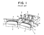
- FIG. 1 the structure shown in FIG. 1 is conventionally employed as this type of the stator winding method and the stator winding structure. That is, what is denoted by numeral 1 in FIG. 1 is a stator which is formed to a ring-shape as a whole and has a plurality of teeth 2 projecting inward and stator insulation covers 3 formed to a ring-shape are disposed to the stator 1 so as to cover the respective teeth 2.
- Windings 4 are wound around the respective teeth 2 through the outer peripheries of the stator insulation covers 3 by a specific winding method using a not shown winding machine and the ends 4a of the windings 4 are caused to automatically become entangled with and directly connected to the respective terminals 6 of the terminal plate 5 of the stator insulation covers 3.
- An object of the present invention made to solve the above problems is to provide a stator winding method and a stator winding structure capable of improving the vibration resistance and impact resistance of windings and preventing the break thereof caused by a temperature change by forming slack portions to the windings when the windings wound around the teeth of a stator are connected to terminals.
- a stator winding method of winding windings around the respective teeth of a stator and connecting the ends of the windings to terminals attached to the terminal plate of the stator insulation covers provided with the stator comprising the steps of positioning a longitudinal rod member between the teeth and the terminals; connecting the windings to the terminals in the state that the windings stride over the longitudinal rod member; and removing the longitudinal rod member to thereby form slack portions to the windings which are located between the teeth and the terminals.
- a stator winding structure for winding windings around the respective teeth of a stator and connecting the ends of the windings to terminals attached to the terminal plate of the stator insulation covers provided with the stator comprises slack portions formed by being caused to stride over a longitudinal rod member which is disposed between the teeth and the terminals when the windings are connected.
- a stator 1 which is formed to a ring-shape and has a plurality of teeth 2 projecting inward and ring-shaped stator insulation covers 3 are disposed to the respective teeth 2 of the stator 1 to insulate the teeth 2 from windings 4.
- the windings 4 are wound around the respective teeth 2 through the outer peripheries of the stator insulation covers 3 by a known specific winding method using a not shown winding machine.
- a longitudinal rod member 10 provided with the winding machine is inserted and positioned between the teeth 2 end the terminals 6 above the teeth 2 before the ends 4a of the windings 4 are connected to the terminals 6 of a terminal plate 5 disposed to the stator 1 integrally with the stator insulation covers 3, the ends 4a are connected to the respective terminals 6 by being caused to become entangled therewith while coming into contact with the upper surface of the longitudinal rod member 10.
- slack portions 4aA are formed to the ends 4a as shown in FIG. 2 when the longitudinal rod member 10 is removed in the direction of an arrow A.
- the longitudinal rod member 10 may be assembled to the winding machine or arranged as an independent system.
- the stator 1 may be applicable to various types of known rotating machines such as a resolver, motor, synchro and the like.
- the slack portions can be formed to the ends of the windings wound around the teeth, whereby vibration resistance and impact resistance can be improved as well as the break of the windings caused by a temperature change can be prevented.
- the reliability of various rotating machines can be greatly improved.
Abstract
Description
- The present invention relates to a stator winding method and a stator winding structure, and more specifically, to a novel improvement in the vibration resistance and impact resistance of windings and the prevention of the break thereof caused by a temperature change, the improvement being achieved by forming slack portions to the windings when they are wound around the teeth of a stator and connected to terminals.
- In general, the structure shown in FIG. 1 is conventionally employed as this type of the stator winding method and the stator winding structure. That is, what is denoted by numeral 1 in FIG. 1 is a stator which is formed to a ring-shape as a whole and has a plurality of
teeth 2 projecting inward and stator insulation covers 3 formed to a ring-shape are disposed to the stator 1 so as to cover therespective teeth 2.Windings 4 are wound around therespective teeth 2 through the outer peripheries of the stator insulation covers 3 by a specific winding method using a not shown winding machine and theends 4a of thewindings 4 are caused to automatically become entangled with and directly connected to therespective terminals 6 of theterminal plate 5 of the stator insulation covers 3. - Since the prior art stator winding method and stator winding structure are arranged as described above, they have the following problems.
- Since the ends of the windings which are wound around the respective teeth are directly wound around the terminals, these ends are stretched between the teeth and the terminals under a tension without any slack. Thus, the ends have low reliability of impact resistance and vibration resistance and prevention of break thereof in use. Thus, the improvement of the reliability has been desired.
- An object of the present invention made to solve the above problems is to provide a stator winding method and a stator winding structure capable of improving the vibration resistance and impact resistance of windings and preventing the break thereof caused by a temperature change by forming slack portions to the windings when the windings wound around the teeth of a stator are connected to terminals.
- According to the present invention, a stator winding method of winding windings around the respective teeth of a stator and connecting the ends of the windings to terminals attached to the terminal plate of the stator insulation covers provided with the stator, the method comprising the steps of positioning a longitudinal rod member between the teeth and the terminals; connecting the windings to the terminals in the state that the windings stride over the longitudinal rod member; and removing the longitudinal rod member to thereby form slack portions to the windings which are located between the teeth and the terminals. Further, according to the present invention, a stator winding structure for winding windings around the respective teeth of a stator and connecting the ends of the windings to terminals attached to the terminal plate of the stator insulation covers provided with the stator comprises slack portions formed by being caused to stride over a longitudinal rod member which is disposed between the teeth and the terminals when the windings are connected.
- The invention will now be described, by way of example, with reference to the accompanying drawings, in which:
- FIG. 1 is a view showing the arrangement of prior art stator windings;
- FIG. 2 is a view showing a stator winding method and a stator winding structure according to the present invention; and
- FIG. 3 is a view showing the state that winding is being performed in FIG. 1.
-
- A preferred embodiment of a stator winding method and a stator winding structure according to the present invention will be described with reference to the drawings. Parts similar to those of the prior art are described using the same numerals.
- As shown in FIG. 3, a stator 1 which is formed to a ring-shape and has a plurality of
teeth 2 projecting inward and ring-shapedstator insulation covers 3 are disposed to therespective teeth 2 of the stator 1 to insulate theteeth 2 fromwindings 4. Thewindings 4 are wound around therespective teeth 2 through the outer peripheries of the stator insulation covers 3 by a known specific winding method using a not shown winding machine. Since alongitudinal rod member 10 provided with the winding machine is inserted and positioned between theteeth 2 end theterminals 6 above theteeth 2 before theends 4a of thewindings 4 are connected to theterminals 6 of aterminal plate 5 disposed to the stator 1 integrally with the stator insulation covers 3, theends 4a are connected to therespective terminals 6 by being caused to become entangled therewith while coming into contact with the upper surface of thelongitudinal rod member 10. On the completion of the connection of theends 4a to theterminal pins 6, slack portions 4aA are formed to theends 4a as shown in FIG. 2 when thelongitudinal rod member 10 is removed in the direction of an arrow A. Thelongitudinal rod member 10 may be assembled to the winding machine or arranged as an independent system. In addition, the stator 1 may be applicable to various types of known rotating machines such as a resolver, motor, synchro and the like. - Since the stator winding method and the stator winding structure according to the present invention are arranged as described above, the slack portions can be formed to the ends of the windings wound around the teeth, whereby vibration resistance and impact resistance can be improved as well as the break of the windings caused by a temperature change can be prevented. Thus, the reliability of various rotating machines can be greatly improved.
Claims (2)
- A stator winding method of winding windings around the respective teeth of a stator and connecting the ends of the windings to terminals attached to the terminal plate of the stator insulation covers provided with the stator, comprising the steps of:positioning a longitudinal rod member between the teeth and the terminals;connecting the windings to the terminals in the state that the windings stride over the longitudinal rod member; andremoving the longitudinal rod member to thereby form slack portions to the windings which are located between the teeth and the terminals.
- A stator winding structure for winding windings around the respective teeth of a stator and connecting the ends of the windings to terminals attached to the terminal plate of the stator insulation covers provided with the stator, comprising slack portions formed by being caused to stride over a longitudinal rod member which is disposed between the teeth and the terminals when the windings are connected.
Applications Claiming Priority (3)
| Application Number | Priority Date | Filing Date | Title |
|---|---|---|---|
| JP313586/97 | 1997-11-14 | ||
| JP31358697 | 1997-11-14 | ||
| JP31358697A JP3299702B2 (en) | 1997-11-14 | 1997-11-14 | Stator winding method and stator winding structure |
Publications (3)
| Publication Number | Publication Date |
|---|---|
| EP0917273A2 true EP0917273A2 (en) | 1999-05-19 |
| EP0917273A3 EP0917273A3 (en) | 2001-08-29 |
| EP0917273B1 EP0917273B1 (en) | 2007-04-25 |
Family
ID=18043105
Family Applications (1)
| Application Number | Title | Priority Date | Filing Date |
|---|---|---|---|
| EP98303290A Expired - Lifetime EP0917273B1 (en) | 1997-11-14 | 1998-04-28 | Stator winding method and system |
Country Status (11)
| Country | Link |
|---|---|
| US (2) | US6044545A (en) |
| EP (1) | EP0917273B1 (en) |
| JP (1) | JP3299702B2 (en) |
| KR (1) | KR100360514B1 (en) |
| BR (1) | BR9801628B1 (en) |
| CA (1) | CA2237486C (en) |
| DE (1) | DE69837645T2 (en) |
| ES (1) | ES2284193T3 (en) |
| ID (1) | ID21319A (en) |
| MY (1) | MY116297A (en) |
| TW (1) | TW443026B (en) |
Cited By (3)
| Publication number | Priority date | Publication date | Assignee | Title |
|---|---|---|---|---|
| EP1276209A1 (en) * | 2001-07-05 | 2003-01-15 | Tamagawa Seiki Kabushiki Kaisha | Terminal connection structure of a resolver stator coil |
| US7356910B2 (en) | 2002-01-23 | 2008-04-15 | Mitsubishi Denki Kabushiki Kaisha | Method of manufacturing a rotation angle detector |
| DE102008061779A1 (en) | 2008-12-11 | 2010-06-17 | Ltn Servotechnik Gmbh | Resolver component and resolver equipped therewith |
Families Citing this family (24)
| Publication number | Priority date | Publication date | Assignee | Title |
|---|---|---|---|---|
| US6847146B2 (en) * | 2000-07-26 | 2005-01-25 | Milwaukee Electric Tool Corporation | Field assembly and methods for assembling a field assembly |
| JP2002125348A (en) * | 2000-10-12 | 2002-04-26 | Suzuki Motor Corp | Wiring connection device |
| JP4696207B2 (en) * | 2001-07-09 | 2011-06-08 | 多摩川精機株式会社 | Resolver stator structure |
| JP3899486B2 (en) * | 2002-04-03 | 2007-03-28 | ミネベア株式会社 | Resolver terminal mounting structure |
| JP2004007902A (en) * | 2002-05-31 | 2004-01-08 | Tamagawa Seiki Co Ltd | Insulating cap structure of rotary machine |
| JP2003344107A (en) * | 2002-05-31 | 2003-12-03 | Tamagawa Seiki Co Ltd | Stator structure for rotation detector |
| JP3811892B2 (en) * | 2002-06-28 | 2006-08-23 | ミネベア株式会社 | Sag formation mechanism of stator winding |
| JP3893087B2 (en) * | 2002-07-25 | 2007-03-14 | ミネベア株式会社 | Winding machine stator mounting jig and stator winding method |
| JP3659640B2 (en) * | 2002-08-08 | 2005-06-15 | 多摩川精機株式会社 | Winding method of rotation detector |
| JP3864380B2 (en) * | 2002-09-25 | 2006-12-27 | ミネベア株式会社 | Resolver input / output terminal structure and resolver connection method using the same |
| KR20050021423A (en) * | 2005-02-07 | 2005-03-07 | 김길평 | Guardrail using bridge can regulate wind pressure |
| US7467456B2 (en) * | 2006-03-02 | 2008-12-23 | Hiwin Mikrosystem Corp. | Method of arranging a resolver |
| JP4760566B2 (en) * | 2006-06-21 | 2011-08-31 | 日本電産株式会社 | Winding mounting method |
| JP5186767B2 (en) * | 2007-01-11 | 2013-04-24 | 日本電産株式会社 | Resolver and method for producing resolver |
| JP5092412B2 (en) * | 2007-01-12 | 2012-12-05 | 日本電産株式会社 | Resolver and method for producing resolver |
| JP5301170B2 (en) * | 2008-01-29 | 2013-09-25 | 株式会社一宮電機 | Resolver stator and resolver |
| US8757268B2 (en) * | 2009-05-22 | 2014-06-24 | Bl Sales & Management, Inc. | Self centering downhole float valve for vertical and lateral wells |
| JP5959270B2 (en) * | 2012-03-30 | 2016-08-02 | 三菱電機株式会社 | Electric motor stator, blower motor and air conditioner |
| US10158268B2 (en) * | 2013-09-17 | 2018-12-18 | Panasonic Intellectual Property Management Co., Ltd. | Brushless DC motor and ventilation device having same mounted therein |
| JP2015082935A (en) * | 2013-10-23 | 2015-04-27 | 日本電産サンキョー株式会社 | Motor and method for connecting winding to terminal pin in motor |
| KR101605630B1 (en) | 2014-09-05 | 2016-03-23 | 대성전기공업 주식회사 | A insulating cover of resolver and mehtod for winding coil thereof |
| JP2016073171A (en) * | 2014-10-02 | 2016-05-09 | 多摩川精機株式会社 | Resolver terminal structure and welding method for the same |
| US20190027307A1 (en) * | 2017-07-18 | 2019-01-24 | Wen Liang Wang | Method of winding a stator core to prevent breakage of wire between pin and winding groove |
| JP7170171B2 (en) * | 2018-11-26 | 2022-11-14 | パナソニックIpマネジメント株式会社 | Stator, motor and blower |
Citations (2)
| Publication number | Priority date | Publication date | Assignee | Title |
|---|---|---|---|---|
| WO1995015607A1 (en) * | 1993-12-03 | 1995-06-08 | Globe Products Inc. | Stator lead wire connection method and apparatus |
| US5659213A (en) * | 1994-02-28 | 1997-08-19 | Nidec Corporation | Spindle motor |
Family Cites Families (2)
| Publication number | Priority date | Publication date | Assignee | Title |
|---|---|---|---|---|
| US5760505A (en) * | 1994-11-07 | 1998-06-02 | Ametek, Inc. | Apparatus and method for introducing wire slack in stator windings |
| US5833166A (en) * | 1996-07-25 | 1998-11-10 | Globe Products Inc. | Stator coil winding and lead wire placing method and apparatus |
-
1997
- 1997-11-14 JP JP31358697A patent/JP3299702B2/en not_active Expired - Fee Related
-
1998
- 1998-04-14 TW TW087105661A patent/TW443026B/en not_active IP Right Cessation
- 1998-04-28 ES ES98303290T patent/ES2284193T3/en not_active Expired - Lifetime
- 1998-04-28 DE DE69837645T patent/DE69837645T2/en not_active Expired - Lifetime
- 1998-04-28 EP EP98303290A patent/EP0917273B1/en not_active Expired - Lifetime
- 1998-04-28 US US09/066,878 patent/US6044545A/en not_active Expired - Fee Related
- 1998-04-30 ID IDP980645A patent/ID21319A/en unknown
- 1998-04-30 KR KR10-1998-0015547A patent/KR100360514B1/en not_active IP Right Cessation
- 1998-05-12 CA CA002237486A patent/CA2237486C/en not_active Expired - Fee Related
- 1998-05-13 BR BRPI9801628-8A patent/BR9801628B1/en not_active IP Right Cessation
- 1998-11-10 MY MYPI98005102A patent/MY116297A/en unknown
- 1998-12-30 US US09/223,393 patent/US6031307A/en not_active Expired - Fee Related
Patent Citations (2)
| Publication number | Priority date | Publication date | Assignee | Title |
|---|---|---|---|---|
| WO1995015607A1 (en) * | 1993-12-03 | 1995-06-08 | Globe Products Inc. | Stator lead wire connection method and apparatus |
| US5659213A (en) * | 1994-02-28 | 1997-08-19 | Nidec Corporation | Spindle motor |
Non-Patent Citations (1)
| Title |
|---|
| BODEN: "Automatische Positionierung loser Wicklungsdrahtenden bewickelter Statoren" ANTRIEBSTECHNIK, vol. 31, no. 9, 1992, pages 84-87, XP000291684 Mainz, Germany * |
Cited By (7)
| Publication number | Priority date | Publication date | Assignee | Title |
|---|---|---|---|---|
| EP1276209A1 (en) * | 2001-07-05 | 2003-01-15 | Tamagawa Seiki Kabushiki Kaisha | Terminal connection structure of a resolver stator coil |
| US6873074B2 (en) | 2001-07-05 | 2005-03-29 | Tamagawa Seiki Kabushiki Kaisha | Terminal connection structure of a resolver stator coil |
| EP1870984A2 (en) * | 2001-07-05 | 2007-12-26 | Tamagawa Seiki Kabushiki Kaisha | Terminal connection structure of a resolver stator coil |
| EP1870984A3 (en) * | 2001-07-05 | 2008-12-31 | Tamagawa Seiki Kabushiki Kaisha | Terminal connection structure of a resolver stator coil |
| US7356910B2 (en) | 2002-01-23 | 2008-04-15 | Mitsubishi Denki Kabushiki Kaisha | Method of manufacturing a rotation angle detector |
| DE10302162B4 (en) * | 2002-01-23 | 2013-11-07 | Mitsubishi Denki K.K. | Method for producing a rotation angle detector |
| DE102008061779A1 (en) | 2008-12-11 | 2010-06-17 | Ltn Servotechnik Gmbh | Resolver component and resolver equipped therewith |
Also Published As
| Publication number | Publication date |
|---|---|
| KR100360514B1 (en) | 2003-01-10 |
| ES2284193T3 (en) | 2007-11-01 |
| MY116297A (en) | 2003-12-31 |
| CA2237486C (en) | 2000-10-31 |
| JP3299702B2 (en) | 2002-07-08 |
| US6044545A (en) | 2000-04-04 |
| DE69837645D1 (en) | 2007-06-06 |
| TW443026B (en) | 2001-06-23 |
| DE69837645T2 (en) | 2008-01-31 |
| JPH11150922A (en) | 1999-06-02 |
| BR9801628A (en) | 1999-12-14 |
| ID21319A (en) | 1999-05-20 |
| EP0917273A3 (en) | 2001-08-29 |
| KR19990044723A (en) | 1999-06-25 |
| BR9801628B1 (en) | 2009-05-05 |
| EP0917273B1 (en) | 2007-04-25 |
| US6031307A (en) | 2000-02-29 |
Similar Documents
| Publication | Publication Date | Title |
|---|---|---|
| EP0917273A2 (en) | Stator winding method and stator winding structure | |
| US6028383A (en) | Resolver stator structure having insulation extended portion with connector pins | |
| US3984712A (en) | End turn shield and winding connector | |
| DE10302162B4 (en) | Method for producing a rotation angle detector | |
| JP3491510B2 (en) | Stator for magnet generator | |
| EP0915558A3 (en) | Quadrature winding retention in a dynamoelectric machine | |
| EP1376825A2 (en) | Slack-forming mechanism for stator coil | |
| US4818910A (en) | Commutator motor with an insulating cover for the rotor shaft | |
| EP1276209A1 (en) | Terminal connection structure of a resolver stator coil | |
| JP3692722B2 (en) | Motor stator | |
| US20080231139A1 (en) | Method for Production of a Commutator, as Well as Commutator | |
| KR20010006313A (en) | Method for fixing a rotor winding | |
| US5448122A (en) | Brush device | |
| JPH0547455Y2 (en) | ||
| JPH0548559U (en) | Motor winding terminal processing device | |
| JPH0357088Y2 (en) | ||
| CN1223495A (en) | Stator winding method and stator winding structure | |
| JPH0441748Y2 (en) | ||
| JPH051970Y2 (en) | ||
| JPH04178142A (en) | Electric motor | |
| JPH01321834A (en) | Stator for rotary electric machine | |
| JPH0641364U (en) | Stator for generator | |
| JPH11308811A (en) | Stator with sensor | |
| JPH1118347A (en) | Motor | |
| JPS6134861Y2 (en) |
Legal Events
| Date | Code | Title | Description |
|---|---|---|---|
| PUAI | Public reference made under article 153(3) epc to a published international application that has entered the european phase |
Free format text: ORIGINAL CODE: 0009012 |
|
| AK | Designated contracting states |
Kind code of ref document: A2 Designated state(s): AT BE CH CY DE DK ES FI FR GB GR IE IT LI LU MC NL PT SE |
|
| AX | Request for extension of the european patent |
Free format text: AL;LT;LV;MK;RO;SI |
|
| PUAL | Search report despatched |
Free format text: ORIGINAL CODE: 0009013 |
|
| AK | Designated contracting states |
Kind code of ref document: A3 Designated state(s): AT BE CH CY DE DK ES FI FR GB GR IE IT LI LU MC NL PT SE |
|
| AX | Request for extension of the european patent |
Free format text: AL;LT;LV;MK;RO;SI |
|
| RIC1 | Information provided on ipc code assigned before grant |
Free format text: 7H 02K 3/50 A, 7H 02K 15/00 B |
|
| 17P | Request for examination filed |
Effective date: 20011203 |
|
| AKX | Designation fees paid |
Free format text: BE CH DE ES FR GB IT LI NL SE |
|
| 17Q | First examination report despatched |
Effective date: 20050603 |
|
| GRAP | Despatch of communication of intention to grant a patent |
Free format text: ORIGINAL CODE: EPIDOSNIGR1 |
|
| RTI1 | Title (correction) |
Free format text: STATOR WINDING METHOD AND SYSTEM |
|
| GRAS | Grant fee paid |
Free format text: ORIGINAL CODE: EPIDOSNIGR3 |
|
| GRAA | (expected) grant |
Free format text: ORIGINAL CODE: 0009210 |
|
| AK | Designated contracting states |
Kind code of ref document: B1 Designated state(s): BE CH DE ES FR GB IT LI NL SE |
|
| REG | Reference to a national code |
Ref country code: GB Ref legal event code: FG4D |
|
| REG | Reference to a national code |
Ref country code: SE Ref legal event code: TRGR |
|
| REG | Reference to a national code |
Ref country code: CH Ref legal event code: NV Representative=s name: WILLIAM BLANC & CIE CONSEILS EN PROPRIETE INDUSTRI Ref country code: CH Ref legal event code: EP |
|
| REF | Corresponds to: |
Ref document number: 69837645 Country of ref document: DE Date of ref document: 20070606 Kind code of ref document: P |
|
| PG25 | Lapsed in a contracting state [announced via postgrant information from national office to epo] |
Ref country code: DE Free format text: LAPSE BECAUSE OF FAILURE TO SUBMIT A TRANSLATION OF THE DESCRIPTION OR TO PAY THE FEE WITHIN THE PRESCRIBED TIME-LIMIT Effective date: 20070726 |
|
| ET | Fr: translation filed | ||
| REG | Reference to a national code |
Ref country code: ES Ref legal event code: FG2A Ref document number: 2284193 Country of ref document: ES Kind code of ref document: T3 |
|
| REG | Reference to a national code |
Ref country code: HK Ref legal event code: WD Ref document number: 1020120 Country of ref document: HK |
|
| PLBE | No opposition filed within time limit |
Free format text: ORIGINAL CODE: 0009261 |
|
| STAA | Information on the status of an ep patent application or granted ep patent |
Free format text: STATUS: NO OPPOSITION FILED WITHIN TIME LIMIT |
|
| 26N | No opposition filed |
Effective date: 20080128 |
|
| PGFP | Annual fee paid to national office [announced via postgrant information from national office to epo] |
Ref country code: ES Payment date: 20090508 Year of fee payment: 12 |
|
| PGFP | Annual fee paid to national office [announced via postgrant information from national office to epo] |
Ref country code: SE Payment date: 20090407 Year of fee payment: 12 Ref country code: NL Payment date: 20090405 Year of fee payment: 12 Ref country code: IT Payment date: 20090421 Year of fee payment: 12 Ref country code: FR Payment date: 20090417 Year of fee payment: 12 |
|
| PGFP | Annual fee paid to national office [announced via postgrant information from national office to epo] |
Ref country code: BE Payment date: 20090422 Year of fee payment: 12 |
|
| PGFP | Annual fee paid to national office [announced via postgrant information from national office to epo] |
Ref country code: CH Payment date: 20090416 Year of fee payment: 12 |
|
| PGFP | Annual fee paid to national office [announced via postgrant information from national office to epo] |
Ref country code: GB Payment date: 20090422 Year of fee payment: 12 |
|
| REG | Reference to a national code |
Ref country code: CH Ref legal event code: PFA Owner name: TAMAGAWA SEIKI KABUSHIKI KAISHA Free format text: TAMAGAWA SEIKI KABUSHIKI KAISHA#1879, OOYASUMI#IIDA-SHI, NAGANO-KEN (JP) -TRANSFER TO- TAMAGAWA SEIKI KABUSHIKI KAISHA#1879, OOYASUMI#IIDA-SHI, NAGANO-KEN (JP) |
|
| BERE | Be: lapsed |
Owner name: TAMAGAWA SEIKI K.K. Effective date: 20100430 |
|
| REG | Reference to a national code |
Ref country code: NL Ref legal event code: V1 Effective date: 20101101 |
|
| EUG | Se: european patent has lapsed | ||
| REG | Reference to a national code |
Ref country code: CH Ref legal event code: PL |
|
| GBPC | Gb: european patent ceased through non-payment of renewal fee |
Effective date: 20100428 |
|
| REG | Reference to a national code |
Ref country code: FR Ref legal event code: ST Effective date: 20101230 |
|
| PG25 | Lapsed in a contracting state [announced via postgrant information from national office to epo] |
Ref country code: NL Free format text: LAPSE BECAUSE OF NON-PAYMENT OF DUE FEES Effective date: 20101101 |
|
| PG25 | Lapsed in a contracting state [announced via postgrant information from national office to epo] |
Ref country code: LI Free format text: LAPSE BECAUSE OF NON-PAYMENT OF DUE FEES Effective date: 20100430 Ref country code: CH Free format text: LAPSE BECAUSE OF NON-PAYMENT OF DUE FEES Effective date: 20100430 |
|
| PG25 | Lapsed in a contracting state [announced via postgrant information from national office to epo] |
Ref country code: BE Free format text: LAPSE BECAUSE OF NON-PAYMENT OF DUE FEES Effective date: 20100430 Ref country code: GB Free format text: LAPSE BECAUSE OF NON-PAYMENT OF DUE FEES Effective date: 20100428 Ref country code: IT Free format text: LAPSE BECAUSE OF NON-PAYMENT OF DUE FEES Effective date: 20100428 |
|
| REG | Reference to a national code |
Ref country code: ES Ref legal event code: FD2A Effective date: 20110715 |
|
| PG25 | Lapsed in a contracting state [announced via postgrant information from national office to epo] |
Ref country code: ES Free format text: LAPSE BECAUSE OF NON-PAYMENT OF DUE FEES Effective date: 20110705 |
|
| PG25 | Lapsed in a contracting state [announced via postgrant information from national office to epo] |
Ref country code: ES Free format text: LAPSE BECAUSE OF NON-PAYMENT OF DUE FEES Effective date: 20100429 |
|
| PG25 | Lapsed in a contracting state [announced via postgrant information from national office to epo] |
Ref country code: FR Free format text: LAPSE BECAUSE OF NON-PAYMENT OF DUE FEES Effective date: 20100430 |
|
| PGFP | Annual fee paid to national office [announced via postgrant information from national office to epo] |
Ref country code: DE Payment date: 20120502 Year of fee payment: 15 |
|
| PG25 | Lapsed in a contracting state [announced via postgrant information from national office to epo] |
Ref country code: SE Free format text: LAPSE BECAUSE OF NON-PAYMENT OF DUE FEES Effective date: 20100429 |
|
| PG25 | Lapsed in a contracting state [announced via postgrant information from national office to epo] |
Ref country code: DE Free format text: LAPSE BECAUSE OF FAILURE TO SUBMIT A TRANSLATION OF THE DESCRIPTION OR TO PAY THE FEE WITHIN THE PRESCRIBED TIME-LIMIT Effective date: 20131101 |
|
| REG | Reference to a national code |
Ref country code: DE Ref legal event code: R119 Ref document number: 69837645 Country of ref document: DE Effective date: 20131101 |