EP0918189A2 - A stick with signal markings - Google Patents
A stick with signal markings Download PDFInfo
- Publication number
- EP0918189A2 EP0918189A2 EP98610040A EP98610040A EP0918189A2 EP 0918189 A2 EP0918189 A2 EP 0918189A2 EP 98610040 A EP98610040 A EP 98610040A EP 98610040 A EP98610040 A EP 98610040A EP 0918189 A2 EP0918189 A2 EP 0918189A2
- Authority
- EP
- European Patent Office
- Prior art keywords
- stick
- switch
- light sources
- light
- stick according
- Prior art date
- Legal status (The legal status is an assumption and is not a legal conclusion. Google has not performed a legal analysis and makes no representation as to the accuracy of the status listed.)
- Withdrawn
Links
Images

Classifications
-
- A—HUMAN NECESSITIES
- A45—HAND OR TRAVELLING ARTICLES
- A45B—WALKING STICKS; UMBRELLAS; LADIES' OR LIKE FANS
- A45B3/00—Sticks combined with other objects
- A45B3/02—Sticks combined with other objects with illuminating devices
- A45B3/04—Sticks combined with other objects with illuminating devices electrical
Definitions
- the present invention relates to a stick with signal markings in particular to aid walking-impaired and blind people, said stick comprising a rod which has a handle at the top, the lower part of the rod being provided with activatable light sources which may be connected to an energy supply via a switch.
- sticks for the blind and crutch-handled sticks. It is known to provide a stick with markings in the form of reflector tapes or tapes in a contrast colour relative to the stick in order to be seen in the traffic. The person using the stick is hereby made more visible to his surroundings. Reflector tapes, however, have almost no effect in daylight, whereas a contrast colour, such as red tapes on a white stick, is most visible in daylight. In the dark, however, none of these signal markings can be seen without being illuminated. When illuminated, the reflector markings have the greatest effect as they reflect the light. It is well-known in this connection that a reflector marking is easier to see if it moves. Additionally, it is expedient that signal markings are provided at the bottom of a stick, as it will be the lowermost end of the stick which is the most moving and thereby the most "signalling" part.
- US 5 588 735 describes a special stick with incorporated alarm and light system which may be activated by the user.
- the stick uses a traditional incandescent bulb which is arranged at the lowermost part of the stick and emits light through a large circular opening with a glass window.
- An incandescent bulb has a relatively poor light intensity, and the circular hole causes the ultimate strength of the stick to be weakened.
- the electrical circuit has a rather great energy consumption.
- DE 38 11 037 A1 describes a stick where the electric bulb is arranged within the tube of the stick at the handle.
- the lowermost part of the stick is made of a transparent material.
- the bulb emits light down through the stick, and this in combination with the long distance from light source to the transparent material results in a weakening of the light intensity from the lowermost part of the stick.
- the structure moreover has the drawback that it cannot be incorporated in existing sticks, but has to be constructed quite specially.
- the transparent part of the stick reduces the ultimate strength of the stick.
- US 4 236 544 describes a stick having a xenon flash tube which generates periodic intensive flashes of light.
- the electrical system for this purpose is relatively complicated and consumes much energy.
- the stick is also constructed with a lower part consisting of transparent glass, clear PVC or the like, which impairs the ultimate strength of the stick considerably.
- the object of the invention is to provide a stick with signal markings which overcomes the above-mentioned drawbacks of known signal markings.
- the novelty of the invention comprises a stick of the type mentioned in the opening paragraph, where the light sources consist of at least one light emitting diode (LED) which preferably emits light in a direction directly away from the stick.
- LED light emitting diode
- the very low energy consumption means that a stick with a standard NiMH battery has enough energy for about 12 hours of uninterrupted use.
- a further advantage of using light emitting diodes of this type is that they have a great light intensity, and they can thus be observed at a distance of about 200 metres.
- the light sources are positioned in recesses in the tube wall, it is ensured that the stick has a greater ultimate strength than the known sticks where entire lengths of glass, clear PVC or like are used in the stick. It is realized in connection with the invention that, alternatively, it is possible to position the light sources externally on the stick.
- the light sources are connected to means causing the diodes to flash when they are activated, increased visibility is achieved, it having been found that a flashing signal marking is extremely conspicuous in the streets. Furthermore, a saving in the power consumption is achieved since the light emitting diodes are suitable for such a flashing system rather than ordinary incandescent bulbs.
- the switch is a motion sensor, preferably a toggle switch in the form of a ball switch arranged such that the switch is turned off until the stick is held in an approximately horizontal position, it is possible to use the stick according to the invention for active signalling e.g. to other road-users.
- the switch is instead arranged in connection with the handle for manual operation by the user of the stick, an alternative solution to active signalling is achieved, which does not require movement of the stick.
- the rod is tubular, and the switch and the energy supply are arranged inside the tube, an expedient embodiment of a stick according to the invention is achieved where the signalling means are shielded against wind and weather.
- the signalling means are shielded against wind and weather.
- the stick is moreover provided with a positionally detectable signal unit allowing the position of the stick to be determined, a discrete, but nevertheless effective means for monitoring particularly senile residents at nursing homes is achieved, thereby making it possible more quickly to come to the rescue of a person who has lost his way.
- a positionally detectable signal unit allowing the position of the stick to be determined, a discrete, but nevertheless effective means for monitoring particularly senile residents at nursing homes is achieved, thereby making it possible more quickly to come to the rescue of a person who has lost his way.
- these persons frequently need a stick in order to be able to walk about on their own. It is therefore advantageous to incorporate the position detection system in the stick.
- the positionally detectable signal unit is constructed such that, by means of discriminant signals, it can communicate with a receiver unit which can identify the position of the stick, a particularly simple solution is achieved, which does not require much space, and the unit can therefore be incorporated in the stick, e.g. in the handle of the stick.
- the unit is provided in a band for the wrist or the arm which is connected to the stick.
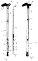
- Figure 1 shows a stick 1 with signal markings in the form of the light means 5.
- the stick consists of a plurality of tube sections 6 which may be adjusted to a suitable height for the user via displacement screws 2.
- the stick is provided with a handle 3 at the top and is terminated by a rubber block 4 at the bottom.
- the central tube section is formed with recesses in which the light means 5 are arranged.
- These light means are formed by light emitting diodes 5, preferably of the LTL-307URK or LTL-353CK-H3 type from Liteon, which emit a strong light and have a low consumption of energy.
- the light emitting diodes may either be positioned in recesses in the tube section, as shown in fig. 1, or externally on the stick.
- Fig. 2 shows an insert intended for mounting inside the stick. It comprises a mounting rail 10 on which a plurality of light emitting diodes 5a is arranged and connected to wires 7 to a relay 8 or other control electronics, e.g. a low energy timer of the LMC555 type from National Semiconductor, for controlling the flashing of the lights. Further, the rail 10 mounts one or more batteries 9 and a switch 11 for activating the light means 5. In figs. 2 and 3, this switch 11 is constructed as a manually activatable switch arranged in connection with the handle 3.
- the stick is equipped with a toggle switch 11 in the form of a ball switch (see fig. 5) e.g. of the RN-OA SP-DT type from Fritec, which automatically activates the light emitting diodes 5a in the light means 5 when the stick is moved up to an approximately horizontal position.
- the angle determining when the toggle switch 11 is activated may also be set at other activation angles, however.
- This ball switch has the advantage over previously used toggle switches, such as e.g. mercury switches, that it is purely mechanical so that it just consumes current at the moment of activation, thereby avoiding the use of harmful chemical compounds, such as mercury.
- the light means 5 are provided with energy from a plurality of batteries 9, which are positioned at the upper part of the stick to ensure a good weight distribution in the stick.
- the batteries 9, the switch 11 and the light units 5a are interconnected by wires 7 inside the tube sections 6.
Abstract
Description
- The present invention relates to a stick with signal markings in particular to aid walking-impaired and blind people, said stick comprising a rod which has a handle at the top, the lower part of the rod being provided with activatable light sources which may be connected to an energy supply via a switch.
- Various types of sticks are available, including sticks for the blind and crutch-handled sticks. It is known to provide a stick with markings in the form of reflector tapes or tapes in a contrast colour relative to the stick in order to be seen in the traffic. The person using the stick is hereby made more visible to his surroundings. Reflector tapes, however, have almost no effect in daylight, whereas a contrast colour, such as red tapes on a white stick, is most visible in daylight. In the dark, however, none of these signal markings can be seen without being illuminated. When illuminated, the reflector markings have the greatest effect as they reflect the light. It is well-known in this connection that a reflector marking is easier to see if it moves. Additionally, it is expedient that signal markings are provided at the bottom of a stick, as it will be the lowermost end of the stick which is the most moving and thereby the most "signalling" part.
- US 5 588 735 describes a special stick with incorporated alarm and light system which may be activated by the user. The stick uses a traditional incandescent bulb which is arranged at the lowermost part of the stick and emits light through a large circular opening with a glass window. An incandescent bulb has a relatively poor light intensity, and the circular hole causes the ultimate strength of the stick to be weakened. Furthermore, the electrical circuit has a rather great energy consumption.
- DE 38 11 037 A1 describes a stick where the electric bulb is arranged within the tube of the stick at the handle. The lowermost part of the stick is made of a transparent material. Thus, the bulb emits light down through the stick, and this in combination with the long distance from light source to the transparent material results in a weakening of the light intensity from the lowermost part of the stick. The structure moreover has the drawback that it cannot be incorporated in existing sticks, but has to be constructed quite specially. The transparent part of the stick reduces the ultimate strength of the stick.
- US 4 236 544 describes a stick having a xenon flash tube which generates periodic intensive flashes of light. The electrical system for this purpose is relatively complicated and consumes much energy. The stick is also constructed with a lower part consisting of transparent glass, clear PVC or the like, which impairs the ultimate strength of the stick considerably.
- Accordingly, the object of the invention is to provide a stick with signal markings which overcomes the above-mentioned drawbacks of known signal markings.
- The novelty of the invention comprises a stick of the type mentioned in the opening paragraph, where the light sources consist of at least one light emitting diode (LED) which preferably emits light in a direction directly away from the stick. This results in an extremely low energy consumption of the light sources on the stick. The very low energy consumption means that a stick with a standard NiMH battery has enough energy for about 12 hours of uninterrupted use. A further advantage of using light emitting diodes of this type is that they have a great light intensity, and they can thus be observed at a distance of about 200 metres.
- When, as stated in
claim 2, the light sources are positioned in recesses in the tube wall, it is ensured that the stick has a greater ultimate strength than the known sticks where entire lengths of glass, clear PVC or like are used in the stick. It is realized in connection with the invention that, alternatively, it is possible to position the light sources externally on the stick. - When, as stated in
claim 4, the light sources are connected to means causing the diodes to flash when they are activated, increased visibility is achieved, it having been found that a flashing signal marking is extremely conspicuous in the streets. Furthermore, a saving in the power consumption is achieved since the light emitting diodes are suitable for such a flashing system rather than ordinary incandescent bulbs. - When, as stated in
claim 5, the switch is a motion sensor, preferably a toggle switch in the form of a ball switch arranged such that the switch is turned off until the stick is held in an approximately horizontal position, it is possible to use the stick according to the invention for active signalling e.g. to other road-users. - When, as stated in
claim 6, the switch is instead arranged in connection with the handle for manual operation by the user of the stick, an alternative solution to active signalling is achieved, which does not require movement of the stick. - When, as stated in
claim 7, the rod is tubular, and the switch and the energy supply are arranged inside the tube, an expedient embodiment of a stick according to the invention is achieved where the signalling means are shielded against wind and weather. However, it is realized in connection with the invention that, alternatively, it is possible to apply the signalling means externally on an existing stick. - When, as stated in claim 8, the stick is moreover provided with a positionally detectable signal unit allowing the position of the stick to be determined, a discrete, but nevertheless effective means for monitoring particularly senile residents at nursing homes is achieved, thereby making it possible more quickly to come to the rescue of a person who has lost his way. In this connection it is realized by the invention that these persons frequently need a stick in order to be able to walk about on their own. It is therefore advantageous to incorporate the position detection system in the stick.
- When, as stated in
claim 9, the positionally detectable signal unit is constructed such that, by means of discriminant signals, it can communicate with a receiver unit which can identify the position of the stick, a particularly simple solution is achieved, which does not require much space, and the unit can therefore be incorporated in the stick, e.g. in the handle of the stick. Another embodiment may be that the unit is provided in a band for the wrist or the arm which is connected to the stick. - The invention will be described more fully below with reference to the accompanying drawing, in which
- fig. 1
- shows a stick according to a first embodiment of the invention,
- fig. 2
- shows an insert for the stick in fig. 1,
- fig. 3
- shows a second embodiment of the stick according to the invention,
- figs. 4 and 5
- show details of a stick according to the preferred embodiment of the invention.
- Figure 1 shows a
stick 1 with signal markings in the form of the light means 5. As is normal, the stick consists of a plurality oftube sections 6 which may be adjusted to a suitable height for the user via displacement screws 2. The stick is provided with ahandle 3 at the top and is terminated by arubber block 4 at the bottom. The central tube section is formed with recesses in which the light means 5 are arranged. These light means are formed bylight emitting diodes 5, preferably of the LTL-307URK or LTL-353CK-H3 type from Liteon, which emit a strong light and have a low consumption of energy. The light emitting diodes may either be positioned in recesses in the tube section, as shown in fig. 1, or externally on the stick. - Fig. 2 shows an insert intended for mounting inside the stick. It comprises a mounting
rail 10 on which a plurality oflight emitting diodes 5a is arranged and connected towires 7 to a relay 8 or other control electronics, e.g. a low energy timer of the LMC555 type from National Semiconductor, for controlling the flashing of the lights. Further, therail 10 mounts one ormore batteries 9 and aswitch 11 for activating the light means 5. In figs. 2 and 3, thisswitch 11 is constructed as a manually activatable switch arranged in connection with thehandle 3. - In another embodiment, the stick is equipped with a
toggle switch 11 in the form of a ball switch (see fig. 5) e.g. of the RN-OA SP-DT type from Fritec, which automatically activates thelight emitting diodes 5a in the light means 5 when the stick is moved up to an approximately horizontal position. The angle determining when thetoggle switch 11 is activated, may also be set at other activation angles, however. This ball switch has the advantage over previously used toggle switches, such as e.g. mercury switches, that it is purely mechanical so that it just consumes current at the moment of activation, thereby avoiding the use of harmful chemical compounds, such as mercury. - As will appear from fig. 4, the light means 5 are provided with energy from a plurality of
batteries 9, which are positioned at the upper part of the stick to ensure a good weight distribution in the stick. Thebatteries 9, theswitch 11 and thelight units 5a are interconnected bywires 7 inside thetube sections 6.
Claims (9)
- A stick with signal markings in particular to aid walking-impaired and blind people, said stick comprising a rod which has a handle at the top, the lower part of the rod being provided with activatable light sources which may be connected to an energy supply via a switch, characterized in that said light sources consist of at least one light emitting diode (LED) which preferably emits light in a direction directly away from the stick.
- A stick according to claim 1, characterized in that the light sources are arranged in recesses in the tube wall.
- A stick according to claim 1, characterized in that the light sources are arranged externally on the stick.
- A stick according to claims 1-3, characterized in that the light sources are connected to means which cause the diodes to flash when said means are activated.
- A stick according to claims 1-4, characterized in that the switch is a motion sensor, preferably a toggle switch in the form of a ball switch arranged such that the switch is turned off until the stick is held in an approximately horizontal position.
- A stick according to claims 1-4, characterized in that the switch is arranged in connection with the handle for manual operation by the user of the stick.
- A stick according to any one of the preceding claims, characterized in that the rod is tubular, and that the switch and the energy supply are arranged inside the tube.
- A stick according to any one of the preceding claims, characterized in that it is moreover provided with a positionally detectable signal unit allowing the position of the stick to be determined.
- A stick according to claim 6, characterized in that the positionally detectable signal unit is constructed such that, by means of discriminant signals, it can communicate with a receiver unit which can identify the position of the stick.
Applications Claiming Priority (4)
| Application Number | Priority Date | Filing Date | Title |
|---|---|---|---|
| DK121997 | 1997-10-24 | ||
| DK121997 | 1997-10-24 | ||
| DK15798 | 1998-02-05 | ||
| DK15798 | 1998-02-05 |
Publications (2)
| Publication Number | Publication Date |
|---|---|
| EP0918189A2 true EP0918189A2 (en) | 1999-05-26 |
| EP0918189A3 EP0918189A3 (en) | 1999-12-15 |
Family
ID=26063421
Family Applications (1)
| Application Number | Title | Priority Date | Filing Date |
|---|---|---|---|
| EP98610040A Withdrawn EP0918189A3 (en) | 1997-10-24 | 1998-10-23 | A stick with signal markings |
Country Status (1)
| Country | Link |
|---|---|
| EP (1) | EP0918189A3 (en) |
Cited By (2)
| Publication number | Priority date | Publication date | Assignee | Title |
|---|---|---|---|---|
| EP1707067A1 (en) * | 2005-03-30 | 2006-10-04 | Andres A. Berl | Walking cane with mechanical and magnetic pick-up devices and illumination source |
| DE202012000319U1 (en) * | 2012-01-16 | 2013-04-18 | Stichting Ontwikkeling En Vervaardiging Van Hulpmiddelen Voor Visueel Gehandicapten | Warning buzzer for placement in or on a portable mobility aid |
Citations (3)
| Publication number | Priority date | Publication date | Assignee | Title |
|---|---|---|---|---|
| US4236544A (en) | 1978-02-24 | 1980-12-02 | Takeshi Osaka | Safety-enhancing walking stick |
| DE3811037A1 (en) | 1988-03-31 | 1989-10-12 | Bernd Bloeser | Walking stick |
| US5588735A (en) | 1994-06-14 | 1996-12-31 | Harada; Noboru | Stick |
Family Cites Families (5)
| Publication number | Priority date | Publication date | Assignee | Title |
|---|---|---|---|---|
| EP0114929A1 (en) * | 1983-01-26 | 1984-08-08 | Daimaru Kogyo Kabushiki Kaisha | Walking cane |
| FR2666968A1 (en) * | 1990-09-20 | 1992-03-27 | Carre Andre | Walking stick (cane) for personal security (safety) |
| US5197501A (en) * | 1991-09-26 | 1993-03-30 | Henry Ragatz | Multi-purpose cane |
| GB2261166A (en) * | 1991-11-06 | 1993-05-12 | David Peter Ogilvie | Light-emitting walking stick |
| US5331990A (en) * | 1992-10-06 | 1994-07-26 | Hall H Eugene | Safety cane |
-
1998
- 1998-10-23 EP EP98610040A patent/EP0918189A3/en not_active Withdrawn
Patent Citations (3)
| Publication number | Priority date | Publication date | Assignee | Title |
|---|---|---|---|---|
| US4236544A (en) | 1978-02-24 | 1980-12-02 | Takeshi Osaka | Safety-enhancing walking stick |
| DE3811037A1 (en) | 1988-03-31 | 1989-10-12 | Bernd Bloeser | Walking stick |
| US5588735A (en) | 1994-06-14 | 1996-12-31 | Harada; Noboru | Stick |
Cited By (2)
| Publication number | Priority date | Publication date | Assignee | Title |
|---|---|---|---|---|
| EP1707067A1 (en) * | 2005-03-30 | 2006-10-04 | Andres A. Berl | Walking cane with mechanical and magnetic pick-up devices and illumination source |
| DE202012000319U1 (en) * | 2012-01-16 | 2013-04-18 | Stichting Ontwikkeling En Vervaardiging Van Hulpmiddelen Voor Visueel Gehandicapten | Warning buzzer for placement in or on a portable mobility aid |
Also Published As
| Publication number | Publication date |
|---|---|
| EP0918189A3 (en) | 1999-12-15 |
Similar Documents
| Publication | Publication Date | Title |
|---|---|---|
| US4611265A (en) | Lighted address display with emergency signal system | |
| FI94681C (en) | Warning triangle for motor vehicles | |
| US6422714B1 (en) | Illuminated, solar powered, vehicle activated, traffic sign | |
| DK1282888T3 (en) | Air navigation device on wind power plants | |
| US6000811A (en) | Hanging emergency light assembly | |
| US20030132852A1 (en) | Illuminated emergency signaling device | |
| US10859254B2 (en) | Luminous protective fence | |
| US6939021B2 (en) | Triangular light assembly with flashing and non-flashing lights | |
| JP3962712B2 (en) | Luminous handrail device | |
| EP0918189A2 (en) | A stick with signal markings | |
| JP2002138426A (en) | Curbstone block emission device | |
| US5000402A (en) | Kite illumination system | |
| JP2008302006A (en) | Stick for elderly person | |
| JP2004102208A (en) | Building material with light emitting device and light emitting device for housing equipment | |
| US20030033739A1 (en) | Safety lighting device | |
| JP2006045817A (en) | Handrail with lighting means, and handrail bracket | |
| CN207878323U (en) | A kind of traffic safety warming device | |
| RU79111U1 (en) | BEACON SIGNAL | |
| JPH0648542Y2 (en) | Self-luminous indicator for ski areas | |
| JPH05280015A (en) | Traffic safety system | |
| KR200237831Y1 (en) | Umbrella with night warning effect | |
| JP2902805B2 (en) | Emergency guide light | |
| JPH1014629A (en) | Umbrella being equipped with warning lamp | |
| CN213118875U (en) | Street lamp that possesses 5G communication function | |
| KR0124413Y1 (en) | Flickering signal rod |
Legal Events
| Date | Code | Title | Description |
|---|---|---|---|
| PUAI | Public reference made under article 153(3) epc to a published international application that has entered the european phase |
Free format text: ORIGINAL CODE: 0009012 |
|
| AK | Designated contracting states |
Kind code of ref document: A2 Designated state(s): AT BE CH CY DE DK ES FI FR GB GR IE IT LI LU MC NL PT SE |
|
| AX | Request for extension of the european patent |
Free format text: AL;LT;LV;MK;RO;SI |
|
| PUAL | Search report despatched |
Free format text: ORIGINAL CODE: 0009013 |
|
| AK | Designated contracting states |
Kind code of ref document: A3 Designated state(s): AT BE CH CY DE DK ES FI FR GB GR IE IT LI LU MC NL PT SE |
|
| AX | Request for extension of the european patent |
Free format text: AL;LT;LV;MK;RO;SI |
|
| AKX | Designation fees paid | ||
| REG | Reference to a national code |
Ref country code: DE Ref legal event code: 8566 |
|
| STAA | Information on the status of an ep patent application or granted ep patent |
Free format text: STATUS: THE APPLICATION IS DEEMED TO BE WITHDRAWN |
|
| 18D | Application deemed to be withdrawn |
Effective date: 20000616 |