EP0918376A2 - Modular connectors - Google Patents
Modular connectors Download PDFInfo
- Publication number
- EP0918376A2 EP0918376A2 EP98121170A EP98121170A EP0918376A2 EP 0918376 A2 EP0918376 A2 EP 0918376A2 EP 98121170 A EP98121170 A EP 98121170A EP 98121170 A EP98121170 A EP 98121170A EP 0918376 A2 EP0918376 A2 EP 0918376A2
- Authority
- EP
- European Patent Office
- Prior art keywords
- terminals
- terminal
- housing
- connector
- electrical
- Prior art date
- Legal status (The legal status is an assumption and is not a legal conclusion. Google has not performed a legal analysis and makes no representation as to the accuracy of the status listed.)
- Granted
Links
Images


Classifications
-
- H—ELECTRICITY
- H01—ELECTRIC ELEMENTS
- H01R—ELECTRICALLY-CONDUCTIVE CONNECTIONS; STRUCTURAL ASSOCIATIONS OF A PLURALITY OF MUTUALLY-INSULATED ELECTRICAL CONNECTING ELEMENTS; COUPLING DEVICES; CURRENT COLLECTORS
- H01R12/00—Structural associations of a plurality of mutually-insulated electrical connecting elements, specially adapted for printed circuits, e.g. printed circuit boards [PCB], flat or ribbon cables, or like generally planar structures, e.g. terminal strips, terminal blocks; Coupling devices specially adapted for printed circuits, flat or ribbon cables, or like generally planar structures; Terminals specially adapted for contact with, or insertion into, printed circuits, flat or ribbon cables, or like generally planar structures
- H01R12/70—Coupling devices
- H01R12/71—Coupling devices for rigid printing circuits or like structures
- H01R12/72—Coupling devices for rigid printing circuits or like structures coupling with the edge of the rigid printed circuits or like structures
- H01R12/722—Coupling devices for rigid printing circuits or like structures coupling with the edge of the rigid printed circuits or like structures coupling devices mounted on the edge of the printed circuits
- H01R12/727—Coupling devices presenting arrays of contacts
-
- H—ELECTRICITY
- H01—ELECTRIC ELEMENTS
- H01R—ELECTRICALLY-CONDUCTIVE CONNECTIONS; STRUCTURAL ASSOCIATIONS OF A PLURALITY OF MUTUALLY-INSULATED ELECTRICAL CONNECTING ELEMENTS; COUPLING DEVICES; CURRENT COLLECTORS
- H01R13/00—Details of coupling devices of the kinds covered by groups H01R12/70 or H01R24/00 - H01R33/00
- H01R13/648—Protective earth or shield arrangements on coupling devices, e.g. anti-static shielding
- H01R13/658—High frequency shielding arrangements, e.g. against EMI [Electro-Magnetic Interference] or EMP [Electro-Magnetic Pulse]
- H01R13/6581—Shield structure
- H01R13/6585—Shielding material individually surrounding or interposed between mutually spaced contacts
-
- H—ELECTRICITY
- H05—ELECTRIC TECHNIQUES NOT OTHERWISE PROVIDED FOR
- H05K—PRINTED CIRCUITS; CASINGS OR CONSTRUCTIONAL DETAILS OF ELECTRIC APPARATUS; MANUFACTURE OF ASSEMBLAGES OF ELECTRICAL COMPONENTS
- H05K1/00—Printed circuits
- H05K1/02—Details
- H05K1/14—Structural association of two or more printed circuits
- H05K1/141—One or more single auxiliary printed circuits mounted on a main printed circuit, e.g. modules, adapters
-
- H—ELECTRICITY
- H05—ELECTRIC TECHNIQUES NOT OTHERWISE PROVIDED FOR
- H05K—PRINTED CIRCUITS; CASINGS OR CONSTRUCTIONAL DETAILS OF ELECTRIC APPARATUS; MANUFACTURE OF ASSEMBLAGES OF ELECTRICAL COMPONENTS
- H05K3/00—Apparatus or processes for manufacturing printed circuits
- H05K3/30—Assembling printed circuits with electric components, e.g. with resistor
- H05K3/306—Lead-in-hole components, e.g. affixing or retention before soldering, spacing means
- H05K3/308—Adaptations of leads
-
- H—ELECTRICITY
- H05—ELECTRIC TECHNIQUES NOT OTHERWISE PROVIDED FOR
- H05K—PRINTED CIRCUITS; CASINGS OR CONSTRUCTIONAL DETAILS OF ELECTRIC APPARATUS; MANUFACTURE OF ASSEMBLAGES OF ELECTRICAL COMPONENTS
- H05K3/00—Apparatus or processes for manufacturing printed circuits
- H05K3/36—Assembling printed circuits with other printed circuits
- H05K3/366—Assembling printed circuits with other printed circuits substantially perpendicularly to each other
Definitions
- This invention relates to electrical connectors. Specifically, it relates to electrical connectors constructed of a plurality of circuit substrate modules, to which mating terminals and other components may be attached.
- Connectors formed of printed circuit boards arranged in side by side relationship have been disclosed.
- One such system is shown in United States 4,521,014.
- the construction shown in this patent would be expensive to produce and difficult to miniaturize.
- United States Application Serial No. 08/784 743 filed 16 January 1997 illustrates modular connectors of a similar type used to form high speed cable interconnections.
- United States Patent Application Serial No. 08/784 744 filed 16 January 1997 illustrates arrangements for surface mounting such high speed connectors. Both of these applications are commonly owned by the assignee of the present application an are incorporated herein by reference.
- This invention relates to electrical connectors and interconnection systems formed in a modular fashion from stacked assemblies of circuit substrate elements.
- Contact terminals, especially receptacle terminals are provided with shielding in the mating region of the terminal.
- High cross talk performance is achieved by shielding that can be carried through the interconnection, with also the possibility of incorporating signal conditioning elements in the connector.
- Terminal carriers for holding a plurality of terminals in position to be mounted on the circuit substrate simultaneously.
- the carriers can be designed to function as a means for retaining modules in a housing and/or transmitting insertion force to press fit terminals.
- Fig. 1a shows an exploded view of a right angle receptacle connector embodying features of the invention.
- the connector 20 includes a plurality of circuit modules 22.
- Each module 22 includes a circuit substrate 24 that can be formed of a substantially planar piece of printed circuit board material, such as that sold under the commercial designation FR4, or other suitable materials.
- the substrate 24 can be formed of a molded or cast piece of a suitable insulative material, especially one receptive to or easily treated to be receptive to the formation of conductive traces on its surface.
- the substrate 24 carries a plurality of conductive traces (see Fig. 2a) extending from the region of one edge, such as edge 24a to the region of a second edge, such as edge 24b.
- ground tracks are interlaced with the terminal traces for shielding of these traces.
- the side of the substrate 24 opposite the side carrying the circuit traces (the side disposed upwardly in Fig. 1a) is covered with a continuous shielding or ground layer.
- Each module has one or more sets of terminals secured on its track receiving side.
- one terminal set comprises a receptacle terminal assembly 26.
- the terminal carrier 26 comprises a housing 28 of insulative material having a plurality of aligned openings 30.
- a receptacle terminal such as a tuning fork terminal 32, is received in each of the openings 30 and is retained therein by retentive barbs 33 on side edges of the terminals.
- the tines 34 of the terminals extend through an offset region 35 to a base section 36 having a surface 38 adapted to be surface mounted on a conductive trace of the substrate 24.
- the surfaces 38 are arranged to be substantially coplanar with the top surface 28c of the housing 28.
- Suitable location and retention structure such as locating/mounting pegs (not shown) may be formed on the housing 28 to aid in location and retention of the terminal carrier on the circuit substrate 24.
- a press fit terminal carrier 40 having a plurality of press fit terminals 42 may be mounted along edge 24b.
- the press fit terminal carrier 40 may also include an extension 44 that comprises structure for transmitting press fit insertion force to the terminals 14. Terminal carriers 26 and 40 are described in greater detail below.
- the connector 20 also includes an insulative housing 46.
- the housing 46 includes a top wall 48 and a front wall 50 having a plurality of a lead-in apertures 52 position to be aligned with the receptacle terminals 32.
- a plurality of interior walls 53 extend between the top wall 48 and the bottom wall 54 to form a plurality of parallel stacked compartments, each of which receives one of the circuit modules 22.
- the housing can include a plurality of ground springs 56 for establishing a ground connection between the circuit modules 22 and a mating connector. Alternatively, as described later, the ground springs 56 can be carried by terminal carrier 26.
- a plurality of circuit modules 22 are inserted into the housing 46 to form a completed right angle connector.
- the modules are retained in the housing by means of an interference fit between the housing and portions of the modules.
- Such an interference fit may be created by sizing terminal carrier 26 and/or the press fit carrier 40 in their thickness or width dimensions, or both, so that there is a suitable interference fit with the slots between the dividing walls 53.
- the modules 22 are supported so that there are spaces 62 between each of the modules. Such spacing allows for other components to be mounted on the module 24, as will be later explained.
- the connector 20 may also include an additional ground spring 58, that is adopted ground the connector to the printed circuit board on which it is mounted.
- the grounded spring 58 is retained by a mounting structure 60 that is received on the locating post 63. Grounding can be carried from modules 22 through contact springs (not shown) similar to ground springs 56, that contact ground spring 58.
- the press fit terminal carrier 40 may include a force transmitting extension 44 that is adopted to bear against the bottom surface of the housing top 48.
- a force transmitting extension 44 that is adopted to bear against the bottom surface of the housing top 48.
- an insertion force may be applied directly to housing 40 by appropriate tooling.
- Fig. 1c is an isometric view of the connector shown in 1b taken from the front of the connector, showing the front face 50 with lead-in apertures 52.
- Fig. 1d is an isometric view showing the top view of the connector 20, with grounding springs 56 extending through slots in the top 48 of the housing and positioned to engage shielding contacts of a mating header..
- a module 22' that is similar to the receptacle module illustrated in Fig. 1a, with the primary difference being that, in place of the receptacle carrier 40, a pin carrier 64 comprising an insulation body 66 and a plurality of contact pins 68, is mounted on circuit substrate 24.
- the circuit substrate 24 has a plurality of circuit traces 70 formed thereon.
- the press fit terminal carrier 40 is secured on one edge of the board with the press fit terminals 42 attached to contact pads 72.
- the pin carrier 64 is applied to another edge of the circuit substrate.
- the pin header 64 may have one or more contact pins 74 that extend beyond the lower surface of body 66 as shown in Fig.
- the pins 74 are adapted to be received in plated through-holes 76 in the circuit substrate.
- the contacts 74 can be substantially flush with the bottom surface of the carrier body 66 (as shown in Fig. 14b), thereby providing for surface mounting of the pin carrier 64 onto the circuit substrate 24.
- the circuit substrate 24 may be populated with appropriate passive or active electronic elements 78 for purposes of signal conditioning or modifying signals carried by conductive traces 70.
- the press fit carrier 40 includes press fit terminals 42 that have surface mounting pads 80 substantially coplanar with the bottom surface of the carrier 40.
- the pads 80 may be integrally formed with the press fit pins 42, for example by bending an integral tab in a U-shape to form the pad 80.
- a suitable header connector may be formed from the modules 22 in essentially the same manner as described with respect to the receptacle connector 20.
- a body 82 of insulative material is formed in a similar manner to the housing 46 of Fig. 1a, with the exception that the front wall 84 of the housing 82 includes an array of integrally formed insulating ferrules 86.
- a shroud 88 is mounted onto the insulative housing 82, with the ferrules 86 received in openings 90 in the base of the shroud.
- the shroud in this embodiment is formed of a conductive material, such as a die cast zinc, for shielding purposes.
- a latch structure 92 may be secured onto the shroud 88 for purposes of latching a cable connector onto the shroud.
- Figs. 4a, 4b and 4c illustrate a module 22'' for forming a cable connector.
- the circuit substrate 24' includes a receptacle carrier 26 generally of the same type as illustrated in Fig. 1a having a plurality of tuning fork contacts 32.
- an insulation displacement contact (IDC) carrier 94 At the end of the substrate 24'' opposite the terminal carrier 26, is an insulation displacement contact (IDC) carrier 94 that includes a plurality of insulation displacement contacts 96 received in an insulative cover 98.
- the bottom surfaces 100 of the IDC terminals are adapted to be surface mounted onto the circuit substrate 24''.
- the terminals 96 are assembled to the cover 98, with the cover positioned to allow insertion of conductors 102 into channels 104 in the cover.
- the cover is pushed toward the terminals 96, causing the conductors 102 to be driven into the IDC contacts 96 and thereby causing the upstanding portions of the terminals to slice through insulation surrounding the conductors 102, as is conventional in such type connectors. Drain wires 105, if present may also be placed in one of the IDC contacts 96.
- metal strain relief ferrules 104 may be applied to the cable 106.
- the strain relief ferrules 102 may be secured to the substrate 24'' by means of pegs or by soldering through vias 108 in the substrate 24''.
- a cable connector module 22'' is formed as shown in Fig.
- Fig. 4c illustrates a receptacle carrier 26 of essentially the same type as shown in Fig. 1a.
- the opposed cantilever sections of each tuning fork terminal formed by the tines 34 and offset portions 35 are joined together at the base 36.
- the plane of base 36 is offset from the plane of portions 34 by the offset defined by the portions 35. The amount of the offset is sufficient for a signal pin to be received between forks 34 and to pass next to base 36, as shown in Fig. 13..
- a cable connector may be formed by inserting a plurality of cable connector modules 22'' into a cable connector housing 110 formed of an insulative material and having a plurality of parallel slots 111 for receiving the modules 22''. As shown in Fig. 5b, a plurality of modules 22'' are fit into the housing 110. A shielded connector is formed by securing metal shields 112, with a suitable strain relief structure about the unit formed by the housing 110 and the modules 22''. The assembled, fully shielded cable connector is shown in Fig. 5c.
- Figs. 6a and 6b illustrate another form of cable connector module 22'' similar to that shown in Fig. 5a except that, instead of the insulation displacement carrier 94, the conductors 102 are stripped and soldered directly onto appropriate contact pads on the circuit substrate.
- Figs. 7a and 7b illustrate a receptacle printed circuit board connector essentially as shown in Fig. 1 with the exception that the modules are placed in alternating orientation to provide for a differential pair arrangement.
- Fig. 8a is an exploded view of an alternative embodiment to the right angle receptacle connector shown in Fig. 1a.
- the receptacle contact carrier 26' includes a surrounding metal shield having contact springs 112 integrally formed with a shield, as will be later described. Contact springs 112 extend through slots 114 in the housing 46.
- Fig. 8b illustrates a modified form of receptacle terminal carrier useful with the Fig. 8a receptacle embodiment, as well as with other receptacle embodiments.
- the carrier 26' has a body 28 having a plurality of terminal receiving openings 30. One of the openings, 30', is relieved along the top edge. The relief allows the center tuning fork terminal 32' to be positioned forwardly of the other terminals 32 by a distance FMLB.
- This provides the receptacle assembly with the capability of a "first make, last break" function with the mating terminal pins, whereby the center pin of an equal length set of pins will engage terminal 32' before the remaining pins engage terminals 32 during mating and will remain in contact with terminal 32' after the remaining pins separate from terminals 32 during unmating.
- This functionality is provided on the receptacle side of the connector and avoid the need for using unequal pin lengths in the mating header.
- Fig. 9a is a cross sectional view of a press fit terminal carrier, such as carrier 40 previously described.
- the body 118 of insulative material has a plurality of slots 120 (Fig. 10) in each of which is received a press lit pin 42.
- Each pin 42 includes a retention section 122 having barbs for retaining the terminal.
- Each terminal further includes a tab 124 that is bent into a U-shape to form a surface mounting pad 80 that is soldered onto a contact pad on the circuit substrate 24.
- the press fit section 128 may be formed in a suitable shape, such as an eye of the needle shape, to be retained in a through-hole 130, by being pressed therein, as is conventional.
- an insulative body 132 includes a plurality of channels 134 formed along a bottom edge thereof.
- a plurality of surface mount terminal members 136 are wrapped about a core section 138 to form surface mount surfaces 140 and 142 that are adapted to be surface mounted respectively to a contact pad 144 on the printed circuit board or a contact pad on a trace of the circuit substrate 24.
- the terminal members 136 can float somewhat and are maintained on body 132 by the bent portions 145 and 147.
- insulative body 146 has a metallic terminal 148 mounted therein.
- the terminal 148 includes a surface mount portion 150 adapted to be soldered onto the circuit substrate 24.
- An opposite end 152 of the terminal extends into a well 156 and has a fusible element, such as a solder ball 158, secured thereto.
- the solder ball 158 is adapted, upon reflow, to effect a solder connection with contact pad 160 on the printed circuit board.
- the insulative housing 162 has a metallic solder terminal 164 secured therein.
- the terminal 164 has a surface mount portion 166 adapted to be surface mounted onto the circuit substrate 24.
- a tail portion 168 is adapted to extend into a plated through-hole 170. Using intrusive reflow techniques, solder paste received in the through-hole 170 fuses the tall section 168 into electrical communication with the plated through-hole 170.
- a shielded receptacle carrier is shown therein.
- the insulative housing 28 carries a plurality of tuning fork type receptacle contacts 32, as previously described.
- a surrounding shield 170 provides electrical shielding of the individual tuning fork contacts 32.
- Each end of the shield 170 is turned underneath the insulative housing 28 to form hold-down sections 172 (Fig. 12) that are soldered onto the circuit substrate 24.
- tabs 174 (Fig. 12) are punched out of the shield 170 and are bent to extend in slots formed in housing 28 between adjacent terminals 32.
- the tabs 174 may be soldered onto suitable grounding contact pads formed on the circuit substrate 174. In this manner, effective shielding about individual terminals or groups of terminals may be effected, as shown in Fig. 12.
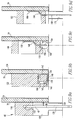
- Fig. 13 is a side sectional view of a right angle receptacle connector received in a mating header connector.
- the contact springs 112 from the shield of the receptacle carrier 26 are positioned to engage the shroud 116 of the header, directly along one edge (at the top) and directly through the ground spring 58 at the bottom.
- Contact pins 113 are received by the tuning fork contacts 32 and the tips thereof pass by the base section 36 by reason of the offset in the tines 34.
- Figs. 14a and 14b shown a shielding arrangement similar to that illustrated in Fig. 11a, 11b and 12, except that the shield 180 is applied to a header carrier as previously illustrated in connection with Fig. 2a.
- the shield 180 may have tabs 182 that are punched from the shield and folded, to substantially surround individual or groups of contact pins 68.
- contact springs 184 may be integrally formed in the shield 180.
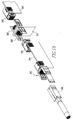
- Fig. 15 shows a cable interconnection arrangement utilizing several of the previously described connectors.
- a cable connector 200 of the type generally illustrated in Figs. 5a, 5b and 5c is used.
- a shielded receptacle carrier as shown in Figs. 12a, 12b and 13 is used in cable connector 200.
- Cable connector 200 mates with a right angle header connector 202 as generally illustrated in Fig. 3b.
- a shielded pin carrier as shown in Figs. 14a and 14b is used on the modules forming header 202.
- Right angle header connector 200 is mounted on one end of a circuit board 204.
- Receptacle connector 206 is mated with a shielded pin header that extends through a back plane 210 to a mirror image arrangement partially represented by the connectors 208', 206' and circuit board 204'.
Abstract
Description
- This invention relates to electrical connectors. Specifically, it relates to electrical connectors constructed of a plurality of circuit substrate modules, to which mating terminals and other components may be attached.
- Connectors formed of printed circuit boards arranged in side by side relationship have been disclosed. One such system is shown in United States 4,521,014. However, the construction shown in this patent would be expensive to produce and difficult to miniaturize.
- Published European Patent Application Serial No. 0 752 739 (commonly owned by the assignee of the present invention and incorporated herein by reference) discloses a modular connector system using side by side stacked circuit substrates to form miniaturized, high speed connectors capable of being manufactured at lower cost.
- United States Application Serial No. 08/784 743 filed 16 January 1997 illustrates modular connectors of a similar type used to form high speed cable interconnections. United States Patent Application Serial No. 08/784 744 filed 16 January 1997 illustrates arrangements for surface mounting such high speed connectors. Both of these applications are commonly owned by the assignee of the present application an are incorporated herein by reference.
- However, a need exists to increase the high frequency performance of these systems and reduce the manufacturing costs. Regarding performance, current widely commercial backplane connector systems having a 2mm grid pitch run at levels of 10% cross talk at 500 picosecond rise times (0.7 GHz). Electrically enhanced versions of these systems approach a performance level of 6% cross talk at 500 picosecond rise times. However, for data transmission especially performance levels of 1% cross talk at signal rise times of 60 to 100 picoseconds (3.5 to 6 GHz) are desirable for systems meant to carry digital signals at a 2.5 Gigabits/second rate.
- This invention relates to electrical connectors and interconnection systems formed in a modular fashion from stacked assemblies of circuit substrate elements. Contact terminals, especially receptacle terminals are provided with shielding in the mating region of the terminal. High cross talk performance is achieved by shielding that can be carried through the interconnection, with also the possibility of incorporating signal conditioning elements in the connector.
- Manufacturing costs are improved by providing terminal carriers for holding a plurality of terminals in position to be mounted on the circuit substrate simultaneously. The carriers can be designed to function as a means for retaining modules in a housing and/or transmitting insertion force to press fit terminals.
-
- Figs. 1a, 1a', 1a'', 1b, 1c and 1d are isometric views of a right angle receptacle connector made in accordance with the invention;
- Figs. 2a and 2b are isometric views of components of a right angle header module;
- Figs. 2c and 2d are isometric views of terminal blocks or carriers used in the module shown in Fig. 2b;
- Figs. 3a and 3b are isometric views of a right angle header using the module shown in Fig. 2b;
- Figs. 4a, 4b and 4c are isometric views of a module or parts thereof used for forming cable connectors;
- Figs. 5a, 5b and 5c are isometric views of a receptacle cable connector using modules of the type shown in Fig. 4b;
- Figs. 6a and 6b show another embodiment of cable connector module similar to that shown in Fig. 4a;
- Figs. 7a and 7b are isometric views of a right angle receptacle connector arranged for differential signal pairs;
- Fig. 8a is an isometric exploded view of a right angle receptacle connector having shielded receptacle contacts;
- Figs. 8b and 8c are isometric views of a receptacle carrier having first make, last break functionality;
- Fig. 9a, 9b, 9c an 9d shown several variants of terminal carriers for forming connections to printed circuit boards;
- Fig. 10 is a front elevational view of the terminal carrier shown in Fig. 9a;
- Fig. 11a is a top elevation of a shielded receptacle carrier and Fig. 11b is a side elevational view of that carrier;
- Fig. 12 is a cross-sectional view taken generally along line A-A of Fig. 13.
- Fig. 13 is a side elevational view of the right angle connector shown in Fig. 8a, mated with a header connector;
- Figs. 14a and 14b are top and side views respectively of a shielded pin carrier for surface mounting on a circuit module, and
- Fig. 15 is an isometric view of an interconnection system made up of several of the connectors illustrated in the proceeding figures.
-
- Fig. 1a shows an exploded view of a right angle receptacle connector embodying features of the invention. The
connector 20 includes a plurality ofcircuit modules 22. Eachmodule 22 includes acircuit substrate 24 that can be formed of a substantially planar piece of printed circuit board material, such as that sold under the commercial designation FR4, or other suitable materials. Also, thesubstrate 24 can be formed of a molded or cast piece of a suitable insulative material, especially one receptive to or easily treated to be receptive to the formation of conductive traces on its surface. Thesubstrate 24 carries a plurality of conductive traces (see Fig. 2a) extending from the region of one edge, such asedge 24a to the region of a second edge, such asedge 24b. Preferably, ground tracks are interlaced with the terminal traces for shielding of these traces. In addition, the side of thesubstrate 24 opposite the side carrying the circuit traces (the side disposed upwardly in Fig. 1a) is covered with a continuous shielding or ground layer. Such constructions are disclosed in above-noted published European patent application. - Each module has one or more sets of terminals secured on its track receiving side. In the embodiment illustrated in Fig. 1a, one terminal set comprises a
receptacle terminal assembly 26. As shown in exploded view in Fig. 1a'', theterminal carrier 26 comprises ahousing 28 of insulative material having a plurality of alignedopenings 30. A receptacle terminal, such as atuning fork terminal 32, is received in each of theopenings 30 and is retained therein byretentive barbs 33 on side edges of the terminals. Thetines 34 of the terminals extend through an offsetregion 35 to abase section 36 having asurface 38 adapted to be surface mounted on a conductive trace of thesubstrate 24. Preferably, thesurfaces 38 are arranged to be substantially coplanar with thetop surface 28c of thehousing 28. Suitable location and retention structure, such as locating/mounting pegs (not shown) may be formed on thehousing 28 to aid in location and retention of the terminal carrier on thecircuit substrate 24. - Similarly, a press
fit terminal carrier 40 having a plurality of pressfit terminals 42 may be mounted alongedge 24b. The pressfit terminal carrier 40 may also include anextension 44 that comprises structure for transmitting press fit insertion force to the terminals 14.Terminal carriers - The
connector 20 also includes aninsulative housing 46. Thehousing 46 includes atop wall 48 and afront wall 50 having a plurality of a lead-inapertures 52 position to be aligned with thereceptacle terminals 32. A plurality ofinterior walls 53 extend between thetop wall 48 and thebottom wall 54 to form a plurality of parallel stacked compartments, each of which receives one of thecircuit modules 22. The housing can include a plurality of ground springs 56 for establishing a ground connection between thecircuit modules 22 and a mating connector. Alternatively, as described later, the ground springs 56 can be carried byterminal carrier 26. - As shown in Fig. 1b, a plurality of
circuit modules 22 are inserted into thehousing 46 to form a completed right angle connector. Preferably, the modules are retained in the housing by means of an interference fit between the housing and portions of the modules. Such an interference fit may be created by sizingterminal carrier 26 and/or thepress fit carrier 40 in their thickness or width dimensions, or both, so that there is a suitable interference fit with the slots between the dividingwalls 53. Themodules 22 are supported so that there arespaces 62 between each of the modules. Such spacing allows for other components to be mounted on themodule 24, as will be later explained. Theconnector 20 may also include anadditional ground spring 58, that is adopted ground the connector to the printed circuit board on which it is mounted. The groundedspring 58 is retained by a mountingstructure 60 that is received on the locatingpost 63. Grounding can be carried frommodules 22 through contact springs (not shown) similar to ground springs 56, thatcontact ground spring 58. - As previously described, the press
fit terminal carrier 40 may include aforce transmitting extension 44 that is adopted to bear against the bottom surface of thehousing top 48. Thus, when a press fit insertion force is applied to the top 48, that force is applied directly, throughextension 44, to thecarrier housing 40 to push thepress fit terminals 42 into the circuit board. This avoids applying shear stress directly to the solder interface between theterminals 42 and thecircuit substrate 24. Alternately, an insertion force may be applied directly tohousing 40 by appropriate tooling. - Fig. 1c is an isometric view of the connector shown in 1b taken from the front of the connector, showing the
front face 50 with lead-inapertures 52. Fig. 1d is an isometric view showing the top view of theconnector 20, with grounding springs 56 extending through slots in the top 48 of the housing and positioned to engage shielding contacts of a mating header.. - Referring to Figs. 2a and 2b, there is illustrated a module 22' that is similar to the receptacle module illustrated in Fig. 1a, with the primary difference being that, in place of the
receptacle carrier 40, apin carrier 64 comprising aninsulation body 66 and a plurality of contact pins 68, is mounted oncircuit substrate 24. As shown in Fig. 2a, thecircuit substrate 24 has a plurality of circuit traces 70 formed thereon. The pressfit terminal carrier 40 is secured on one edge of the board with thepress fit terminals 42 attached to contactpads 72. Thepin carrier 64 is applied to another edge of the circuit substrate. In one variant, thepin header 64 may have one or more contact pins 74 that extend beyond the lower surface ofbody 66 as shown in Fig. 2c. Thepins 74 are adapted to be received in plated through-holes 76 in the circuit substrate. Alternately, thecontacts 74 can be substantially flush with the bottom surface of the carrier body 66 (as shown in Fig. 14b), thereby providing for surface mounting of thepin carrier 64 onto thecircuit substrate 24. - As shown in Fig. 2d, the
circuit substrate 24 may be populated with appropriate passive or activeelectronic elements 78 for purposes of signal conditioning or modifying signals carried byconductive traces 70. - As shown in Fig. 2d, the
press fit carrier 40 includes pressfit terminals 42 that havesurface mounting pads 80 substantially coplanar with the bottom surface of thecarrier 40. Thepads 80 may be integrally formed with the press fit pins 42, for example by bending an integral tab in a U-shape to form thepad 80. - As shown in the exploded view of Fig. 3a and assembled view of Fig. 3b, a suitable header connector may be formed from the
modules 22 in essentially the same manner as described with respect to thereceptacle connector 20. In this form of a connector, abody 82 of insulative material is formed in a similar manner to thehousing 46 of Fig. 1a, with the exception that thefront wall 84 of thehousing 82 includes an array of integrally formed insulatingferrules 86. Ashroud 88 is mounted onto theinsulative housing 82, with theferrules 86 received inopenings 90 in the base of the shroud. The shroud in this embodiment is formed of a conductive material, such as a die cast zinc, for shielding purposes. Alatch structure 92 may be secured onto theshroud 88 for purposes of latching a cable connector onto the shroud. - Figs. 4a, 4b and 4c illustrate a module 22'' for forming a cable connector. In this version, the circuit substrate 24' includes a
receptacle carrier 26 generally of the same type as illustrated in Fig. 1a having a plurality oftuning fork contacts 32. At the end of the substrate 24'' opposite theterminal carrier 26, is an insulation displacement contact (IDC)carrier 94 that includes a plurality ofinsulation displacement contacts 96 received in aninsulative cover 98. The bottom surfaces 100 of the IDC terminals are adapted to be surface mounted onto the circuit substrate 24''. As is conventional, theterminals 96 are assembled to thecover 98, with the cover positioned to allow insertion ofconductors 102 intochannels 104 in the cover. To attach the conductors, the cover is pushed toward theterminals 96, causing theconductors 102 to be driven into theIDC contacts 96 and thereby causing the upstanding portions of the terminals to slice through insulation surrounding theconductors 102, as is conventional in such type connectors. Drain wires 105, if present may also be placed in one of theIDC contacts 96. For additional securing of the cables, metalstrain relief ferrules 104 may be applied to thecable 106. Thestrain relief ferrules 102 may be secured to the substrate 24'' by means of pegs or by soldering throughvias 108 in the substrate 24''. A cable connector module 22'' is formed as shown in Fig. 4b by applying thereceptacle carrier 26 and theIDC terminal carrier 94 to the substrate 24''. Fig. 4c illustrates areceptacle carrier 26 of essentially the same type as shown in Fig. 1a. It should be noted that the opposed cantilever sections of each tuning fork terminal formed by thetines 34 and offsetportions 35, are joined together at thebase 36. The plane ofbase 36 is offset from the plane ofportions 34 by the offset defined by theportions 35. The amount of the offset is sufficient for a signal pin to be received betweenforks 34 and to pass next to base 36, as shown in Fig. 13.. - As shown in Figs. 5a, 5b and 5c, a cable connector may be formed by inserting a plurality of cable connector modules 22'' into a
cable connector housing 110 formed of an insulative material and having a plurality of parallel slots 111 for receiving the modules 22''. As shown in Fig. 5b, a plurality of modules 22'' are fit into thehousing 110. A shielded connector is formed by securingmetal shields 112, with a suitable strain relief structure about the unit formed by thehousing 110 and the modules 22''. The assembled, fully shielded cable connector is shown in Fig. 5c. - Figs. 6a and 6b illustrate another form of cable connector module 22'' similar to that shown in Fig. 5a except that, instead of the
insulation displacement carrier 94, theconductors 102 are stripped and soldered directly onto appropriate contact pads on the circuit substrate. - Figs. 7a and 7b illustrate a receptacle printed circuit board connector essentially as shown in Fig. 1 with the exception that the modules are placed in alternating orientation to provide for a differential pair arrangement.
- Fig. 8a is an exploded view of an alternative embodiment to the right angle receptacle connector shown in Fig. 1a. In this embodiment, the receptacle contact carrier 26' includes a surrounding metal shield having contact springs 112 integrally formed with a shield, as will be later described. Contact springs 112 extend through
slots 114 in thehousing 46. - Fig. 8b illustrates a modified form of receptacle terminal carrier useful with the Fig. 8a receptacle embodiment, as well as with other receptacle embodiments. The carrier 26' has a
body 28 having a plurality of terminal receivingopenings 30. One of the openings, 30', is relieved along the top edge. The relief allows the center tuning fork terminal 32' to be positioned forwardly of theother terminals 32 by a distance FMLB. This provides the receptacle assembly with the capability of a "first make, last break" function with the mating terminal pins, whereby the center pin of an equal length set of pins will engage terminal 32' before the remaining pins engageterminals 32 during mating and will remain in contact with terminal 32' after the remaining pins separate fromterminals 32 during unmating. This functionality is provided on the receptacle side of the connector and avoid the need for using unequal pin lengths in the mating header. - Fig. 9a is a cross sectional view of a press fit terminal carrier, such as
carrier 40 previously described. In this arrangement, thebody 118 of insulative material has a plurality of slots 120 (Fig. 10) in each of which is received a press litpin 42. Eachpin 42 includes aretention section 122 having barbs for retaining the terminal. Each terminal further includes atab 124 that is bent into a U-shape to form asurface mounting pad 80 that is soldered onto a contact pad on thecircuit substrate 24. Thepress fit section 128 may be formed in a suitable shape, such as an eye of the needle shape, to be retained in a through-hole 130, by being pressed therein, as is conventional. - In another form of mounting illustrated in Fig. 9b, an
insulative body 132 includes a plurality of channels 134 formed along a bottom edge thereof. A plurality of surface mountterminal members 136 are wrapped about acore section 138 to form surface mount surfaces 140 and 142 that are adapted to be surface mounted respectively to acontact pad 144 on the printed circuit board or a contact pad on a trace of thecircuit substrate 24. Theterminal members 136 can float somewhat and are maintained onbody 132 by thebent portions 145 and 147. - In another variant shown in Fig. 9c,
insulative body 146 has ametallic terminal 148 mounted therein. The terminal 148 includes asurface mount portion 150 adapted to be soldered onto thecircuit substrate 24. An opposite end 152 of the terminal extends into a well 156 and has a fusible element, such as asolder ball 158, secured thereto. Thesolder ball 158 is adapted, upon reflow, to effect a solder connection withcontact pad 160 on the printed circuit board. - Another embodiment of printed circuit board mounting is shown in Fig. 9d. The
insulative housing 162 has ametallic solder terminal 164 secured therein. The terminal 164 has asurface mount portion 166 adapted to be surface mounted onto thecircuit substrate 24. Atail portion 168 is adapted to extend into a plated through-hole 170. Using intrusive reflow techniques, solder paste received in the through-hole 170 fuses thetall section 168 into electrical communication with the plated through-hole 170. - Referring to Figs. 11a and 11b, a shielded receptacle carrier is shown therein. In this embodiment, the
insulative housing 28 carries a plurality of tuning forktype receptacle contacts 32, as previously described. In addition, a surroundingshield 170 provides electrical shielding of the individualtuning fork contacts 32. Each end of theshield 170 is turned underneath theinsulative housing 28 to form hold-down sections 172 (Fig. 12) that are soldered onto thecircuit substrate 24. In order to shield individual terminals, tabs 174 (Fig. 12) are punched out of theshield 170 and are bent to extend in slots formed inhousing 28 betweenadjacent terminals 32. Thetabs 174 may be soldered onto suitable grounding contact pads formed on thecircuit substrate 174. In this manner, effective shielding about individual terminals or groups of terminals may be effected, as shown in Fig. 12. - Fig. 13 is a side sectional view of a right angle receptacle connector received in a mating header connector. As shown, in this arrangement, the contact springs 112 from the shield of the
receptacle carrier 26 are positioned to engage theshroud 116 of the header, directly along one edge (at the top) and directly through theground spring 58 at the bottom. Contact pins 113 are received by thetuning fork contacts 32 and the tips thereof pass by thebase section 36 by reason of the offset in thetines 34. - Figs. 14a and 14b shown a shielding arrangement similar to that illustrated in Fig. 11a, 11b and 12, except that the
shield 180 is applied to a header carrier as previously illustrated in connection with Fig. 2a. In this arrangement, theshield 180 may havetabs 182 that are punched from the shield and folded, to substantially surround individual or groups of contact pins 68. In addition, contact springs 184 may be integrally formed in theshield 180. - Fig. 15 shows a cable interconnection arrangement utilizing several of the previously described connectors. If the system is single ended, a
cable connector 200 of the type generally illustrated in Figs. 5a, 5b and 5c is used. For improved high speed capabilities, a shielded receptacle carrier as shown in Figs. 12a, 12b and 13 is used incable connector 200.Cable connector 200 mates with a rightangle header connector 202 as generally illustrated in Fig. 3b. Again, if improved high speed performance is desired, a shielded pin carrier as shown in Figs. 14a and 14b is used on themodules forming header 202. Rightangle header connector 200 is mounted on one end of acircuit board 204. A rightangle receptacle connector 206 of the type illustrated generally in Fig. 1a or, for higher speeds, using a shielded receptacle contact carrier, as shown in Fig. 8a, is used.Receptacle connector 206 is mated with a shielded pin header that extends through aback plane 210 to a mirror image arrangement partially represented by the connectors 208', 206' and circuit board 204'. - Manufacturing costs are improved by the use of terminal carrier assemblies that locate and accurately place multiple terminals simultaneously. Housings for the carriers are formed with flat surfaces that allow placement by pick and place equipment. By the use of the shielding arrangements show, high speed interconnections with low cost cross talk have be achieved.
- While the present invention has been described in connection with the preferred embodiments of the various figures, it is to be understood that other similar embodiments may be used or modifications and additions may be made to the described embodiment for performing the same function of the present invention without deviating therefrom. Therefore, the present invention should not be limited to any single embodiment, but rather construed in breadth and scope in accordance with the recitation of the appended claims.
Claims (11)
- An electrical connector having a mating interface and a mounting interface comprising:a) at least one circuit substrate having a body and a plurality of conductive circuit traces carried by the body, the traces extending from a first region of the body adjacent the mating interface to a second region of the body adjacent the mounting interface;b) a housing formed of electrically insulative material mounted on the body in at least one of the first and second regions;c) a plurality of electrical terminals carried by the housing in a manner to associate each of the terminals with one of the traces; andd) means for maintaining a plurality of the circuit substrates in a substantially parallel assembled state.
- An electrical connector as in claim 1, wherein the terminals include surface mount portions for mounting the terminals on the traces.
- An electrical connector as in claim 1, wherein the housing includes a shield member for electrically shielding the terminals.
- An electrical connector as in claim 3, wherein the shield member includes means for securing the housing onto the circuit substrate by surface mounting techniques; or wherein the shield member includes portions positioned in shielding relationship with respect to at least one of the terminals.
- An electrical connector as in claim 1, wherein the terminal has a press fit section and the housing includes a force transmitting portion for receiving an insertion force for pressing the terminal into the circuit substrate and transmitting the insertion force to the terminal.
- An electrical connector as in claim 1, wherein said plurality of terminals have a deformable element disposed along said mounting interface for establishing electrical contact with a circuit element on which the connector is mounted; in particular wherein the deformable element is heat deformable; and in particular wherein the deformable element is a solder ball.
- An electrical connector as in claim 1, wherein the housing includes structure for receiving the body and the body is secured to the structure by an interference fit; or wherein an open zone is present on one side of the circuit substrate for receiving electronic elements mounted on the circuit substrate.
- A method of making an electrical connector comprising:a) forming an electrical substrate element comprising an insulative body having first and second edge portions spaced from each other and a plurality of conductive traces extending from a region adjacent the first edge to a region adjacent the second edge;b) forming an electrical connection interface at the region adjacent the first edge by placing a body having a plurality of electrical contact terminals in the first region with each terminal being positioned for attaching to one of the conductive traces;c) electrically connecting each terminal to one of the traces; andd) mounting the circuit substrate in a housing to present the contact terminals in a position for mating with a mating connector.
- The method of claim 8, further comprising the step of securing an electrically conductive element to each of the circuit traces at said second region.
- The method as in claim 8, wherein the step of electrical connecting each electrical terminal to a circuit trace comprises surface mounting; or wherein the step of mounting the circuit substrate in the housing includes establishing an interference fit between said body and the housing.
- An electrical connector comprising an insulative body, and a substantially linear array of receptacle contact terminals mounted on the body and adapted to receive a mating contact along an insertion direction, at least one of said terminals being offset along said insertion direction from the other of the contacts.
Applications Claiming Priority (2)
| Application Number | Priority Date | Filing Date | Title |
|---|---|---|---|
| US974536 | 1997-11-19 | ||
| US08/974,536 US5924899A (en) | 1997-11-19 | 1997-11-19 | Modular connectors |
Publications (3)
| Publication Number | Publication Date |
|---|---|
| EP0918376A2 true EP0918376A2 (en) | 1999-05-26 |
| EP0918376A3 EP0918376A3 (en) | 2001-03-28 |
| EP0918376B1 EP0918376B1 (en) | 2006-03-22 |
Family
ID=25522148
Family Applications (1)
| Application Number | Title | Priority Date | Filing Date |
|---|---|---|---|
| EP98121170A Expired - Lifetime EP0918376B1 (en) | 1997-11-19 | 1998-11-12 | Modular connectors and method of making the same |
Country Status (4)
| Country | Link |
|---|---|
| US (2) | US5924899A (en) |
| EP (1) | EP0918376B1 (en) |
| JP (1) | JPH11224742A (en) |
| DE (1) | DE69833904T2 (en) |
Cited By (5)
| Publication number | Priority date | Publication date | Assignee | Title |
|---|---|---|---|---|
| EP0971451A2 (en) * | 1998-07-10 | 2000-01-12 | Berg Electronics Manufacturing B.V. | Modular high speed connector |
| NL1013741C2 (en) * | 1999-12-03 | 2001-06-06 | Fci S Hertogenbosch B V | Shielded connector assembly. |
| WO2001057962A1 (en) * | 2000-02-03 | 2001-08-09 | Tyco Electronics Corporation | Electrical connector including a housing that holds parallel circuit boards |
| GB2508679A (en) * | 2012-12-07 | 2014-06-11 | Wintec Ind Inc | Printed circuit board with notch-mounted pins |
| US20150162680A1 (en) * | 2013-12-05 | 2015-06-11 | Tyco Electronics Corporation | Daughter card assembly and communication system including the same |
Families Citing this family (134)
| Publication number | Priority date | Publication date | Assignee | Title |
|---|---|---|---|---|
| EP0951667A4 (en) | 1996-11-01 | 2002-03-06 | Golden Entpr Inc | Personalized automated operator position |
| FR2771223B1 (en) * | 1997-11-19 | 2000-01-14 | Entrelec Sa | INTERFACE DEVICE BETWEEN EQUIPMENT OF A SYSTEM |
| US20020098743A1 (en) | 1998-04-17 | 2002-07-25 | Schell Mark S. | Power connector |
| US6319075B1 (en) | 1998-04-17 | 2001-11-20 | Fci Americas Technology, Inc. | Power connector |
| US7314377B2 (en) * | 1998-04-17 | 2008-01-01 | Fci Americas Technology, Inc. | Electrical power connector |
| DE19825971C1 (en) * | 1998-06-10 | 1999-11-11 | Harting Kgaa | Multipin electrical plug connector, e.g. for printed circuit board |
| US6634889B2 (en) * | 1998-08-03 | 2003-10-21 | Dell Products L.P. | Cross-connected card-edge socket connector and card-edge |
| US6471547B1 (en) * | 1999-06-01 | 2002-10-29 | John T. Venaleck | Electrical connector for high density signal interconnections and method of making the same |
| WO2001003247A1 (en) * | 1999-07-02 | 2001-01-11 | General Dynamics Information Systems, Inc. | Impedance-controlled connector |
| US6485322B1 (en) * | 1999-10-01 | 2002-11-26 | Jds Uniphase Corporation | Removable latch and bezel EMI grounding feature for fiber-optic transceivers |
| US6171115B1 (en) | 2000-02-03 | 2001-01-09 | Tyco Electronics Corporation | Electrical connector having circuit boards and keying for different types of circuit boards |
| US6824391B2 (en) | 2000-02-03 | 2004-11-30 | Tyco Electronics Corporation | Electrical connector having customizable circuit board wafers |
| US6435897B1 (en) * | 2000-04-10 | 2002-08-20 | Storcase Technology, Inc. | Compact PCI connector guide |
| US6478625B2 (en) * | 2000-07-11 | 2002-11-12 | Bernard R. Tolmie | Electrical-optical hybrid connector |
| US6283792B1 (en) * | 2000-07-11 | 2001-09-04 | Bernard R. Tolmie | Extruded metallic electrical connector assembly and method of producing same |
| GB2385722B (en) * | 2000-12-06 | 2004-07-28 | Ept Gmbh & Co Kg | Plug-in connector |
| NL1017519C2 (en) * | 2001-03-07 | 2002-09-10 | Fci S Hertogenbosch B V | Cable connector has multiple contacts in rectangular matrix which are connected to cable cores and three-piece metal EMI screening box |
| NL1017518C2 (en) * | 2001-03-07 | 2002-09-10 | Fci S Hertogenbosch B V | Multiple contact screened connector for telecommunication pairs, uses modular intermediate contacts to provide EMI shielding |
| US6540522B2 (en) | 2001-04-26 | 2003-04-01 | Tyco Electronics Corporation | Electrical connector assembly for orthogonally mating circuit boards |
| JP2002343504A (en) * | 2001-05-11 | 2002-11-29 | Sumitomo Electric Ind Ltd | Diode, and connector serving as resistor |
| US6641410B2 (en) | 2001-06-07 | 2003-11-04 | Teradyne, Inc. | Electrical solder ball contact |
| US6612857B2 (en) | 2001-07-05 | 2003-09-02 | Bernard R. Tolmie | Electrical connector system and method having optical and/or cooling capability |
| USD473941S1 (en) | 2001-08-27 | 2003-04-29 | Kimberly-Clark Worldwide, Inc. | Flexible connecting device |
| USD486909S1 (en) | 2001-08-27 | 2004-02-17 | Kimberly-Clark Worldwide, Inc. | Bendable connecting device |
| USD466607S1 (en) | 2001-08-27 | 2002-12-03 | Kimberly-Clark Worldwide, Inc. | Flexible connector |
| USD476731S1 (en) | 2001-08-27 | 2003-07-01 | Kimberly-Clark Worldwide, Inc. | Bendable connector |
| JP3727567B2 (en) * | 2001-10-23 | 2005-12-14 | ヒロセ電機株式会社 | Intermediate board electrical connector |
| US6821146B2 (en) * | 2002-01-07 | 2004-11-23 | Bernard R. Tolmie | Hybrid connector system and method |
| US6764349B2 (en) * | 2002-03-29 | 2004-07-20 | Teradyne, Inc. | Matrix connector with integrated power contacts |
| US6705895B2 (en) | 2002-04-25 | 2004-03-16 | Tyco Electronics Corporation | Orthogonal interface for connecting circuit boards carrying differential pairs |
| US6638079B1 (en) * | 2002-05-21 | 2003-10-28 | Hon Hai Precision Ind. Co., Ltd. | Customizable electrical connector |
| US6623310B1 (en) * | 2002-05-21 | 2003-09-23 | Hon Hai Precision Ind. Co., Ltd. | High density electrical connector assembly with reduced insertion force |
| US6762941B2 (en) * | 2002-07-15 | 2004-07-13 | Teradyne, Inc. | Techniques for connecting a set of connecting elements using an improved latching apparatus |
| US20040018773A1 (en) * | 2002-07-29 | 2004-01-29 | Fci Americas Technology, Inc. | Printed circuit board assembly having a BGA connection |
| US6685510B1 (en) | 2002-10-22 | 2004-02-03 | Hon Hai Precision Ind. Co., Ltd. | Electrical cable connector |
| US6899547B1 (en) * | 2002-12-04 | 2005-05-31 | Stanley M. Chang | Multi-chip connector module having one or more semiconductor dice |
| US6819569B1 (en) * | 2002-12-06 | 2004-11-16 | Thin Film Technology Corp. | Impedance equalization module |
| US6743050B1 (en) | 2002-12-10 | 2004-06-01 | Hon Hai Precision Ind. Co., Ltd. | Cable assembly with latch mechanism |
| US6926553B2 (en) * | 2003-06-19 | 2005-08-09 | Hon Hai Precision Ind. Co., Ltd. | Cable assembly with improved grounding means |
| US6786771B2 (en) * | 2002-12-20 | 2004-09-07 | Teradyne, Inc. | Interconnection system with improved high frequency performance |
| US6780027B2 (en) | 2003-01-28 | 2004-08-24 | Fci Americas Technology, Inc. | Power connector with vertical male AC power contacts |
| US20040147169A1 (en) * | 2003-01-28 | 2004-07-29 | Allison Jeffrey W. | Power connector with safety feature |
| JP3964353B2 (en) * | 2003-05-22 | 2007-08-22 | タイコエレクトロニクスアンプ株式会社 | Connector assembly |
| US6848950B2 (en) * | 2003-05-23 | 2005-02-01 | Fci Americas Technology, Inc. | Multi-interface power contact and electrical connector including same |
| US6918774B2 (en) * | 2003-06-18 | 2005-07-19 | Hon Hai Precision Ind. Co., Ltd | Electrical connector having long circuit boards |
| US6857912B2 (en) * | 2003-06-25 | 2005-02-22 | Hon Hai Precision Ind. Co., Ltd | Cable assembly with internal circuit modules |
| US6814620B1 (en) | 2003-07-01 | 2004-11-09 | Hon Hai Precision Ind. Co. Ltd. | Electrical connector |
| US6939174B2 (en) * | 2003-07-01 | 2005-09-06 | Hon Hai Precision Ind. Co., Ltd. | Cable assembly with internal circuit modules |
| US6739910B1 (en) | 2003-07-11 | 2004-05-25 | Hon Hai Precision Ind. Co., Ltd. | Cable assembly with internal circuit modules |
| US7059907B2 (en) | 2003-07-24 | 2006-06-13 | Fci Americas Technology, Inc. | Modular electrical connector |
| WO2005053102A2 (en) * | 2003-11-21 | 2005-06-09 | Ohio Associated Enterprises Llc | Cable assembly and method of making |
| US7285018B2 (en) | 2004-06-23 | 2007-10-23 | Amphenol Corporation | Electrical connector incorporating passive circuit elements |
| US6910914B1 (en) * | 2004-08-11 | 2005-06-28 | Hon Hai Precision Ind. Co., Ltd. | Shielded cable end connector assembly |
| CN101099271A (en) * | 2005-01-11 | 2008-01-02 | Fci公司 | Board-to-board connector |
| US7361055B2 (en) * | 2005-01-14 | 2008-04-22 | Molex Incorporated | Modular filter connector |
| US7147512B2 (en) * | 2005-04-19 | 2006-12-12 | Hon Hai Precision Ind. Co., Ltd. | Connector assembly |
| US7134913B1 (en) * | 2005-04-21 | 2006-11-14 | Tyco Electronics Corporation | Connector assembly with mating guide surfaces |
| US20090291593A1 (en) | 2005-06-30 | 2009-11-26 | Prescott Atkinson | High frequency broadside-coupled electrical connector |
| US7376215B2 (en) * | 2005-12-27 | 2008-05-20 | Honeywell International Inc. | Measurement of ash composition using scanning high voltage X-ray sensor |
| GB2436897A (en) * | 2006-04-03 | 2007-10-10 | Brand Rex Ltd | Stepped electrical connector |
| US7484989B2 (en) * | 2006-11-29 | 2009-02-03 | Ohio Associated Enterprises, Llc | Low friction cable assembly latch |
| US20080166928A1 (en) * | 2007-01-10 | 2008-07-10 | Liang Tang | Compliant pin |
| US20080318453A1 (en) * | 2007-06-20 | 2008-12-25 | Dancison Philip M | Compliant pin |
| US8187019B2 (en) | 2008-09-09 | 2012-05-29 | Molex Incorporated | Connector with integrated latch assembly |
| EP2332217B1 (en) * | 2008-09-30 | 2012-08-01 | Fci | Lead frame assembly for an electrical connector |
| USD619099S1 (en) | 2009-01-30 | 2010-07-06 | Fci Americas Technology, Inc. | Electrical connector |
| US8323049B2 (en) | 2009-01-30 | 2012-12-04 | Fci Americas Technology Llc | Electrical connector having power contacts |
| US8926377B2 (en) | 2009-11-13 | 2015-01-06 | Amphenol Corporation | High performance, small form factor connector with common mode impedance control |
| US8475177B2 (en) * | 2010-01-20 | 2013-07-02 | Ohio Associated Enterprises, Llc | Backplane cable interconnection |
| EP2539971A4 (en) | 2010-02-24 | 2014-08-20 | Amphenol Corp | High bandwidth connector |
| CN107069274B (en) | 2010-05-07 | 2020-08-18 | 安费诺有限公司 | High performance cable connector |
| US8382524B2 (en) | 2010-05-21 | 2013-02-26 | Amphenol Corporation | Electrical connector having thick film layers |
| US20110287663A1 (en) | 2010-05-21 | 2011-11-24 | Gailus Mark W | Electrical connector incorporating circuit elements |
| US8636543B2 (en) | 2011-02-02 | 2014-01-28 | Amphenol Corporation | Mezzanine connector |
| WO2013059317A1 (en) | 2011-10-17 | 2013-04-25 | Amphenol Corporation | Electrical connector with hybrid shield |
| US9022812B2 (en) * | 2011-11-02 | 2015-05-05 | Fci Americas Technology Llc | Electrical connector with reduced normal force |
| US8784122B2 (en) * | 2011-11-14 | 2014-07-22 | Airborn, Inc. | Low-profile right-angle electrical connector assembly |
| US8591257B2 (en) | 2011-11-17 | 2013-11-26 | Amphenol Corporation | Electrical connector having impedance matched intermediate connection points |
| US8715006B2 (en) * | 2012-06-11 | 2014-05-06 | Tyco Electronics Corporation | Circuit board having plated thru-holes and ground columns |
| CN108336593B (en) | 2012-06-29 | 2019-12-17 | 安费诺有限公司 | Low-cost high-performance radio frequency connector |
| CN104704682B (en) | 2012-08-22 | 2017-03-22 | 安费诺有限公司 | High-frequency electrical connector |
| US20160093985A1 (en) * | 2013-02-20 | 2016-03-31 | Foxconn Interconnect Technology Limited | High speed high density connector assembly |
| WO2014160356A1 (en) | 2013-03-13 | 2014-10-02 | Amphenol Corporation | Housing for a speed electrical connector |
| US9484674B2 (en) | 2013-03-14 | 2016-11-01 | Amphenol Corporation | Differential electrical connector with improved skew control |
| US20140301052A1 (en) * | 2013-03-15 | 2014-10-09 | Wintec Industries, Inc. | Conductive Mechanical Support at Interface of Printed Circuit Board |
| US9246274B2 (en) | 2013-03-15 | 2016-01-26 | Panduit Corp. | Communication connectors having crosstalk compensation networks |
| US9065213B2 (en) * | 2013-07-03 | 2015-06-23 | Tyco Electronics Corporation | Electrical connector for transmitting data signals |
| EP3641074A1 (en) * | 2013-09-25 | 2020-04-22 | Virginia Panel Corporation | High speed data module for high life cycle interconnect device |
| US9196985B2 (en) * | 2014-01-09 | 2015-11-24 | Tyco Electronics Corporation | Configurable electrical connector assembly |
| US9450344B2 (en) | 2014-01-22 | 2016-09-20 | Amphenol Corporation | High speed, high density electrical connector with shielded signal paths |
| US10263351B2 (en) * | 2014-07-11 | 2019-04-16 | Fci Usa Llc | Orthogonal electrical connector system |
| CN107112696B (en) | 2014-11-12 | 2020-06-09 | 安费诺有限公司 | Very high speed, high density electrical interconnect system with impedance control in the mating region |
| WO2017007429A1 (en) | 2015-07-07 | 2017-01-12 | Amphenol Fci Asia Pte. Ltd. | Electrical connector |
| WO2017015470A1 (en) | 2015-07-23 | 2017-01-26 | Amphenol TCS | Extender module for modular connector |
| WO2017210276A1 (en) | 2016-05-31 | 2017-12-07 | Amphenol Corporation | High performance cable termination |
| US10651603B2 (en) | 2016-06-01 | 2020-05-12 | Amphenol Fci Connectors Singapore Pte. Ltd. | High speed electrical connector |
| WO2018039164A1 (en) | 2016-08-23 | 2018-03-01 | Amphenol Corporation | Connector configurable for high performance |
| TWI797094B (en) | 2016-10-19 | 2023-04-01 | 美商安芬諾股份有限公司 | Compliant shield for very high speed, high density electrical interconnection |
| CN114498109A (en) | 2017-08-03 | 2022-05-13 | 安费诺有限公司 | Cable connector for high speed interconnect |
| DE102017213863A1 (en) * | 2017-08-09 | 2019-02-14 | Robert Bosch Gmbh | A pressure sensor for measuring a pressure of a fluid and a method of manufacturing a pressure sensor for measuring a pressure of a fluid |
| US11710917B2 (en) | 2017-10-30 | 2023-07-25 | Amphenol Fci Asia Pte. Ltd. | Low crosstalk card edge connector |
| US10446959B2 (en) * | 2017-10-31 | 2019-10-15 | Seagate Technology Llc | Printed circuit board mounted cable apparatus and methods thereof |
| US10601181B2 (en) | 2017-12-01 | 2020-03-24 | Amphenol East Asia Ltd. | Compact electrical connector |
| US10777921B2 (en) | 2017-12-06 | 2020-09-15 | Amphenol East Asia Ltd. | High speed card edge connector |
| US10665973B2 (en) | 2018-03-22 | 2020-05-26 | Amphenol Corporation | High density electrical connector |
| CN112514175B (en) | 2018-04-02 | 2022-09-09 | 安达概念股份有限公司 | Controlled impedance compliant cable termination |
| WO2020039666A1 (en) * | 2018-08-24 | 2020-02-27 | 株式会社村田製作所 | Electrical connector set and circuit board on which said electrical connector set is mounted |
| CN208862209U (en) | 2018-09-26 | 2019-05-14 | 安费诺东亚电子科技(深圳)有限公司 | A kind of connector and its pcb board of application |
| WO2020073460A1 (en) | 2018-10-09 | 2020-04-16 | Amphenol Commercial Products (Chengdu) Co. Ltd. | High-density edge connector |
| TWM576774U (en) | 2018-11-15 | 2019-04-11 | 香港商安費諾(東亞)有限公司 | Metal case with anti-displacement structure and connector thereof |
| US10931062B2 (en) | 2018-11-21 | 2021-02-23 | Amphenol Corporation | High-frequency electrical connector |
| US11381015B2 (en) | 2018-12-21 | 2022-07-05 | Amphenol East Asia Ltd. | Robust, miniaturized card edge connector |
| US11189943B2 (en) | 2019-01-25 | 2021-11-30 | Fci Usa Llc | I/O connector configured for cable connection to a midboard |
| WO2020154526A1 (en) | 2019-01-25 | 2020-07-30 | Fci Usa Llc | I/o connector configured for cabled connection to the midboard |
| US11189971B2 (en) | 2019-02-14 | 2021-11-30 | Amphenol East Asia Ltd. | Robust, high-frequency electrical connector |
| CN113728521A (en) | 2019-02-22 | 2021-11-30 | 安费诺有限公司 | High performance cable connector assembly |
| TWM582251U (en) | 2019-04-22 | 2019-08-11 | 香港商安費諾(東亞)有限公司 | Connector set with hidden locking mechanism and socket connector thereof |
| EP3973597A4 (en) | 2019-05-20 | 2023-06-28 | Amphenol Corporation | High density, high speed electrical connector |
| US11735852B2 (en) | 2019-09-19 | 2023-08-22 | Amphenol Corporation | High speed electronic system with midboard cable connector |
| US11588277B2 (en) | 2019-11-06 | 2023-02-21 | Amphenol East Asia Ltd. | High-frequency electrical connector with lossy member |
| TW202127754A (en) | 2019-11-06 | 2021-07-16 | 香港商安費諾(東亞)有限公司 | High-frequency electrical connector with interlocking segments |
| WO2021154718A1 (en) | 2020-01-27 | 2021-08-05 | Fci Usa Llc | High speed, high density direct mate orthogonal connector |
| CN115428275A (en) | 2020-01-27 | 2022-12-02 | 富加宜(美国)有限责任公司 | High speed connector |
| CN113258325A (en) | 2020-01-28 | 2021-08-13 | 富加宜(美国)有限责任公司 | High-frequency middle plate connector |
| DE102020104100B3 (en) | 2020-02-17 | 2021-08-05 | Interplex NAS Electronics GmbH | PCB corner connector and card connector arrangement |
| TWM625349U (en) | 2020-03-13 | 2022-04-11 | 大陸商安費諾商用電子產品(成都)有限公司 | Reinforcing member, electrical connector, circuit board assembly and insulating body |
| US11728585B2 (en) | 2020-06-17 | 2023-08-15 | Amphenol East Asia Ltd. | Compact electrical connector with shell bounding spaces for receiving mating protrusions |
| US11831092B2 (en) | 2020-07-28 | 2023-11-28 | Amphenol East Asia Ltd. | Compact electrical connector |
| US11652307B2 (en) | 2020-08-20 | 2023-05-16 | Amphenol East Asia Electronic Technology (Shenzhen) Co., Ltd. | High speed connector |
| CN212874843U (en) | 2020-08-31 | 2021-04-02 | 安费诺商用电子产品(成都)有限公司 | Electrical connector |
| CN215816516U (en) | 2020-09-22 | 2022-02-11 | 安费诺商用电子产品(成都)有限公司 | Electrical connector |
| CN213636403U (en) | 2020-09-25 | 2021-07-06 | 安费诺商用电子产品(成都)有限公司 | Electrical connector |
| US11569613B2 (en) | 2021-04-19 | 2023-01-31 | Amphenol East Asia Ltd. | Electrical connector having symmetrical docking holes |
| USD1002553S1 (en) | 2021-11-03 | 2023-10-24 | Amphenol Corporation | Gasket for connector |
Citations (6)
| Publication number | Priority date | Publication date | Assignee | Title |
|---|---|---|---|---|
| US4017770A (en) * | 1974-11-22 | 1977-04-12 | Applicazione Elettrotelefoniche Spa | Connecting device for telecommunication circuits |
| FR2448235A1 (en) * | 1979-02-05 | 1980-08-29 | Sadar | Connector for miniature PCB - has conventional connector half along board edge accepting plug-on control modules forming continuous control surface |
| US5383095A (en) * | 1993-10-29 | 1995-01-17 | The Whitaker Corporation | Circuit board and edge-mountable connector therefor, and method of preparing a circuit board edge |
| US5421746A (en) * | 1993-09-13 | 1995-06-06 | Berg Technology, Inc. | Orientation and positioning device for electrical connectors |
| US5539620A (en) * | 1994-06-16 | 1996-07-23 | Northern Telecom Limited | Electronic modules, circuit packs and sealing arrangements |
| WO1997012418A2 (en) * | 1995-09-26 | 1997-04-03 | Siemens Aktiengesellschaft | Contact component for a distributor in a telecommunication facility |
Family Cites Families (29)
| Publication number | Priority date | Publication date | Assignee | Title |
|---|---|---|---|---|
| US3035244A (en) * | 1959-06-12 | 1962-05-15 | Aveni Anthony | Flexible pin extension adapter plug |
| US3208028A (en) * | 1963-04-30 | 1965-09-21 | Ind Electronic Hardware Corp | Multilayer circuitry with interrupted lines |
| US3432801A (en) * | 1966-10-31 | 1969-03-11 | Dynamics Corp America | Patchboard programming system |
| US3564343A (en) * | 1968-09-24 | 1971-02-16 | Reliance Electric Co | Computer programming apparatus |
| US4008941A (en) * | 1976-03-04 | 1977-02-22 | Amp Incorporated | Printed circuit board housing system |
| US4157612A (en) * | 1977-12-27 | 1979-06-12 | Bell Telephone Laboratories, Incorporated | Method for improving the transmission properties of a connectorized flat cable interconnection assembly |
| US4148543A (en) * | 1978-04-28 | 1979-04-10 | General Dynamics Corporation | Suppressor for electromagnetic interference |
| US4206963A (en) * | 1979-04-20 | 1980-06-10 | Amp Incorporated | Connector filtered adapter assembly |
| US4265549A (en) * | 1979-05-21 | 1981-05-05 | Centronics Data Computer Corp. | Flat flexible printed circuit cable for a print head |
| US4382653A (en) * | 1980-12-04 | 1983-05-10 | Avco Corporation | Connector |
| US4457574A (en) * | 1982-02-05 | 1984-07-03 | Automation Industries, Inc. | Electromagnetically shielded connector |
| US4477022A (en) * | 1982-02-23 | 1984-10-16 | Amp Incorporated | Polarizing and latch arrangement for an electrical connector |
| US4571014A (en) * | 1984-05-02 | 1986-02-18 | At&T Bell Laboratories | High frequency modular connector |
| US4689721A (en) * | 1986-01-10 | 1987-08-25 | Trw Inc. | Dual printed circuit board module |
| US4806107A (en) * | 1987-10-16 | 1989-02-21 | American Telephone And Telegraph Company, At&T Bell Laboratories | High frequency connector |
| US4861272A (en) * | 1988-03-31 | 1989-08-29 | E. I. Du Pont De Nemours And Company | Impedance controlled connector interface |
| US4846727A (en) * | 1988-04-11 | 1989-07-11 | Amp Incorporated | Reference conductor for improving signal integrity in electrical connectors |
| JPH0769759B2 (en) * | 1988-09-08 | 1995-07-31 | 三菱電機株式会社 | Memory card connection mechanism |
| US4975084A (en) * | 1988-10-17 | 1990-12-04 | Amp Incorporated | Electrical connector system |
| ES2070283T3 (en) * | 1989-10-10 | 1995-06-01 | Whitaker Corp | CONTRAPLANE CONNECTOR WITH ADAPTED IMPEDANCES. |
| GB8928777D0 (en) * | 1989-12-20 | 1990-02-28 | Amp Holland | Sheilded backplane connector |
| GB9003241D0 (en) * | 1990-02-13 | 1990-04-11 | Gore W L & Ass Uk | Shielded connector |
| US5055069A (en) * | 1990-06-08 | 1991-10-08 | E. I. Du Pont De Nemours And Company | Connectors with ground structure |
| US5118300A (en) * | 1991-05-23 | 1992-06-02 | Amp Incorporated | Active electrical connector |
| NL9300971A (en) * | 1993-06-04 | 1995-01-02 | Framatome Connectors Belgium | Circuit board connector assembly. |
| JP2623435B2 (en) * | 1993-09-17 | 1997-06-25 | 日本航空電子工業株式会社 | Isometric right angle connector |
| US5470244A (en) * | 1993-10-05 | 1995-11-28 | Thomas & Betts Corporation | Electrical connector having reduced cross-talk |
| US5591035A (en) * | 1994-10-06 | 1997-01-07 | The Whitaker Corporation | Electrical connector with shortened contact |
| US5605477A (en) * | 1995-01-13 | 1997-02-25 | The Whitaker Corporation | Flexible etched circuit assembly |
-
1997
- 1997-11-19 US US08/974,536 patent/US5924899A/en not_active Expired - Lifetime
-
1998
- 1998-11-12 DE DE69833904T patent/DE69833904T2/en not_active Expired - Lifetime
- 1998-11-12 EP EP98121170A patent/EP0918376B1/en not_active Expired - Lifetime
- 1998-11-19 JP JP10328742A patent/JPH11224742A/en active Pending
-
1999
- 1999-04-27 US US09/300,037 patent/US6102747A/en not_active Expired - Lifetime
Patent Citations (6)
| Publication number | Priority date | Publication date | Assignee | Title |
|---|---|---|---|---|
| US4017770A (en) * | 1974-11-22 | 1977-04-12 | Applicazione Elettrotelefoniche Spa | Connecting device for telecommunication circuits |
| FR2448235A1 (en) * | 1979-02-05 | 1980-08-29 | Sadar | Connector for miniature PCB - has conventional connector half along board edge accepting plug-on control modules forming continuous control surface |
| US5421746A (en) * | 1993-09-13 | 1995-06-06 | Berg Technology, Inc. | Orientation and positioning device for electrical connectors |
| US5383095A (en) * | 1993-10-29 | 1995-01-17 | The Whitaker Corporation | Circuit board and edge-mountable connector therefor, and method of preparing a circuit board edge |
| US5539620A (en) * | 1994-06-16 | 1996-07-23 | Northern Telecom Limited | Electronic modules, circuit packs and sealing arrangements |
| WO1997012418A2 (en) * | 1995-09-26 | 1997-04-03 | Siemens Aktiengesellschaft | Contact component for a distributor in a telecommunication facility |
Cited By (11)
| Publication number | Priority date | Publication date | Assignee | Title |
|---|---|---|---|---|
| EP0971451A2 (en) * | 1998-07-10 | 2000-01-12 | Berg Electronics Manufacturing B.V. | Modular high speed connector |
| EP0971451A3 (en) * | 1998-07-10 | 2001-09-05 | Berg Electronics Manufacturing B.V. | Modular high speed connector |
| NL1013741C2 (en) * | 1999-12-03 | 2001-06-06 | Fci S Hertogenbosch B V | Shielded connector assembly. |
| EP1107369A1 (en) * | 1999-12-03 | 2001-06-13 | F.C.I. - Framatome Connectors International | Shielded connector assembly |
| WO2001057962A1 (en) * | 2000-02-03 | 2001-08-09 | Tyco Electronics Corporation | Electrical connector including a housing that holds parallel circuit boards |
| DE10195326B3 (en) * | 2000-02-03 | 2011-12-08 | Tyco Electronics Corp. | Electrical connector with a parallel board receiving housing |
| GB2508679A (en) * | 2012-12-07 | 2014-06-11 | Wintec Ind Inc | Printed circuit board with notch-mounted pins |
| CN103872481A (en) * | 2012-12-07 | 2014-06-18 | 美威特工业股份有限公司 | Discrete-Pin Printed-Circuit Mounting with Notches |
| GB2508679B (en) * | 2012-12-07 | 2016-01-13 | Wintec Ind Inc | Discrete-pin printed-circuit mounting with notches |
| US20150162680A1 (en) * | 2013-12-05 | 2015-06-11 | Tyco Electronics Corporation | Daughter card assembly and communication system including the same |
| US9735481B2 (en) * | 2013-12-05 | 2017-08-15 | Te Connectivity Corporation | Daughter card assembly and communication system including the same |
Also Published As
| Publication number | Publication date |
|---|---|
| EP0918376A3 (en) | 2001-03-28 |
| JPH11224742A (en) | 1999-08-17 |
| US6102747A (en) | 2000-08-15 |
| US5924899A (en) | 1999-07-20 |
| EP0918376B1 (en) | 2006-03-22 |
| DE69833904D1 (en) | 2006-05-11 |
| DE69833904T2 (en) | 2007-02-22 |
Similar Documents
| Publication | Publication Date | Title |
|---|---|---|
| US5924899A (en) | Modular connectors | |
| US6083047A (en) | Modular electrical PCB assembly connector | |
| CA2225151C (en) | Connector with integrated pcb assembly | |
| JP3412771B2 (en) | Electrical connector assembly | |
| EP0405454B1 (en) | Coaxial contact element | |
| US6808419B1 (en) | Electrical connector having enhanced electrical performance | |
| JP3399979B2 (en) | Bent or right angle electrical connectors, electrical receptacles, electrical headers and conductive shields | |
| US6641438B1 (en) | High speed, high density backplane connector | |
| EP0836756B1 (en) | Connector with integrated pcb assembly | |
| EP0270598B1 (en) | Shielded electrical connector | |
| US6042394A (en) | Right-angle connector | |
| US7632107B2 (en) | Board-to-board connector | |
| EP0220210B1 (en) | Electrical connector for an electrical cable | |
| EP1538716A2 (en) | Electrical connector with circuit board module | |
| EP1023747B1 (en) | Connector system | |
| US6109976A (en) | Modular high speed connector | |
| US20070042619A1 (en) | Electrical connector having a ground plane with independently configurable contacts | |
| WO1997037404A1 (en) | Connector assembly with shielded modules | |
| US7188408B2 (en) | Method of making a straddle mount connector | |
| US7112072B2 (en) | Ground bus for an electrical connector | |
| US6190196B1 (en) | Cable connector assembly | |
| KR20060057990A (en) | Multipole coaxial cable connector and assembling method for connector | |
| US6692273B1 (en) | Straddle mount connector | |
| WO1999026321A1 (en) | Shielded electrical connector | |
| EP1102361A2 (en) | Electrical connector with wire management system |
Legal Events
| Date | Code | Title | Description |
|---|---|---|---|
| PUAI | Public reference made under article 153(3) epc to a published international application that has entered the european phase |
Free format text: ORIGINAL CODE: 0009012 |
|
| AK | Designated contracting states |
Kind code of ref document: A2 Designated state(s): BE DE FR GB IE IT NL SE |
|
| AX | Request for extension of the european patent |
Free format text: AL;LT;LV;MK;RO;SI |
|
| PUAL | Search report despatched |
Free format text: ORIGINAL CODE: 0009013 |
|
| AK | Designated contracting states |
Kind code of ref document: A3 Designated state(s): AT BE CH CY DE DK ES FI FR GB GR IE IT LI LU MC NL PT SE |
|
| AX | Request for extension of the european patent |
Free format text: AL;LT;LV;MK;RO;SI |
|
| 17P | Request for examination filed |
Effective date: 20010919 |
|
| AKX | Designation fees paid |
Free format text: BE DE FR GB IE IT LU |
|
| RBV | Designated contracting states (corrected) |
Designated state(s): BE DE FR GB IE IT LU NL SE |
|
| RBV | Designated contracting states (corrected) |
Designated state(s): BE DE FR GB IE IT NL SE |
|
| 17Q | First examination report despatched |
Effective date: 20030701 |
|
| GRAP | Despatch of communication of intention to grant a patent |
Free format text: ORIGINAL CODE: EPIDOSNIGR1 |
|
| RTI1 | Title (correction) |
Free format text: MODULAR CONNECTORS AND METHOD OF MAKING THE SAME |
|
| RBV | Designated contracting states (corrected) |
Designated state(s): BE DE FI FR GB IE IT NL SE |
|
| GRAS | Grant fee paid |
Free format text: ORIGINAL CODE: EPIDOSNIGR3 |
|
| GRAA | (expected) grant |
Free format text: ORIGINAL CODE: 0009210 |
|
| RAP1 | Party data changed (applicant data changed or rights of an application transferred) |
Owner name: FCI |
|
| RIC1 | Information provided on ipc code assigned before grant |
Ipc: H01R 12/32 20060101AFI20060126BHEP |
|
| AK | Designated contracting states |
Kind code of ref document: B1 Designated state(s): BE DE FI FR GB IE IT NL SE |
|
| PG25 | Lapsed in a contracting state [announced via postgrant information from national office to epo] |
Ref country code: NL Free format text: LAPSE BECAUSE OF FAILURE TO SUBMIT A TRANSLATION OF THE DESCRIPTION OR TO PAY THE FEE WITHIN THE PRESCRIBED TIME-LIMIT Effective date: 20060322 Ref country code: IT Free format text: LAPSE BECAUSE OF FAILURE TO SUBMIT A TRANSLATION OF THE DESCRIPTION OR TO PAY THE FEE WITHIN THE PRE;WARNING: LAPSES OF ITALIAN PATENTS WITH EFFECTIVE DATE BEFORE 2007 MAY HAVE OCCURRED AT ANY TIME BEFORE 2007. THE CORRECT EFFECTIVE DATE MAY BE DIFFERENT FROM THE ONE RECORDED.SCRIBED TIME-LIMIT Effective date: 20060322 Ref country code: BE Free format text: LAPSE BECAUSE OF FAILURE TO SUBMIT A TRANSLATION OF THE DESCRIPTION OR TO PAY THE FEE WITHIN THE PRESCRIBED TIME-LIMIT Effective date: 20060322 |
|
| REG | Reference to a national code |
Ref country code: GB Ref legal event code: FG4D |
|
| REG | Reference to a national code |
Ref country code: SE Ref legal event code: TRGR |
|
| REG | Reference to a national code |
Ref country code: IE Ref legal event code: FG4D |
|
| REF | Corresponds to: |
Ref document number: 69833904 Country of ref document: DE Date of ref document: 20060511 Kind code of ref document: P |
|
| NLV1 | Nl: lapsed or annulled due to failure to fulfill the requirements of art. 29p and 29m of the patents act | ||
| ET | Fr: translation filed | ||
| PG25 | Lapsed in a contracting state [announced via postgrant information from national office to epo] |
Ref country code: IE Free format text: LAPSE BECAUSE OF NON-PAYMENT OF DUE FEES Effective date: 20061113 |
|
| PLBE | No opposition filed within time limit |
Free format text: ORIGINAL CODE: 0009261 |
|
| STAA | Information on the status of an ep patent application or granted ep patent |
Free format text: STATUS: NO OPPOSITION FILED WITHIN TIME LIMIT |
|
| 26N | No opposition filed |
Effective date: 20061227 |
|
| GBPC | Gb: european patent ceased through non-payment of renewal fee |
Effective date: 20061112 |
|
| PG25 | Lapsed in a contracting state [announced via postgrant information from national office to epo] |
Ref country code: GB Free format text: LAPSE BECAUSE OF NON-PAYMENT OF DUE FEES Effective date: 20061112 |
|
| PG25 | Lapsed in a contracting state [announced via postgrant information from national office to epo] |
Ref country code: FI Free format text: LAPSE BECAUSE OF FAILURE TO SUBMIT A TRANSLATION OF THE DESCRIPTION OR TO PAY THE FEE WITHIN THE PRESCRIBED TIME-LIMIT Effective date: 20060322 |
|
| REG | Reference to a national code |
Ref country code: FR Ref legal event code: CA |
|
| REG | Reference to a national code |
Ref country code: DE Ref legal event code: R082 Ref document number: 69833904 Country of ref document: DE Representative=s name: BEETZ & PARTNER MBB PATENT- UND RECHTSANWAELTE, DE Effective date: 20120419 Ref country code: DE Ref legal event code: R082 Ref document number: 69833904 Country of ref document: DE Representative=s name: BEETZ & PARTNER MBB PATENTANWAELTE, DE Effective date: 20120419 Ref country code: DE Ref legal event code: R082 Ref document number: 69833904 Country of ref document: DE Representative=s name: BEETZ & PARTNER PATENT- UND RECHTSANWAELTE, DE Effective date: 20120419 Ref country code: DE Ref legal event code: R081 Ref document number: 69833904 Country of ref document: DE Owner name: FCI, FR Free format text: FORMER OWNER: FCI, VERSAILLES, FR Effective date: 20120419 |
|
| REG | Reference to a national code |
Ref country code: FR Ref legal event code: PLFP Year of fee payment: 18 |
|
| PGFP | Annual fee paid to national office [announced via postgrant information from national office to epo] |
Ref country code: IT Payment date: 20151112 Year of fee payment: 18 Ref country code: DE Payment date: 20151130 Year of fee payment: 18 |
|
| PGFP | Annual fee paid to national office [announced via postgrant information from national office to epo] |
Ref country code: FR Payment date: 20151027 Year of fee payment: 18 Ref country code: SE Payment date: 20151106 Year of fee payment: 18 |
|
| REG | Reference to a national code |
Ref country code: DE Ref legal event code: R119 Ref document number: 69833904 Country of ref document: DE |
|
| REG | Reference to a national code |
Ref country code: SE Ref legal event code: EUG |
|
| REG | Reference to a national code |
Ref country code: FR Ref legal event code: ST Effective date: 20170731 |
|
| PG25 | Lapsed in a contracting state [announced via postgrant information from national office to epo] |
Ref country code: SE Free format text: LAPSE BECAUSE OF NON-PAYMENT OF DUE FEES Effective date: 20161113 |
|
| PG25 | Lapsed in a contracting state [announced via postgrant information from national office to epo] |
Ref country code: FR Free format text: LAPSE BECAUSE OF NON-PAYMENT OF DUE FEES Effective date: 20161130 Ref country code: IT Free format text: LAPSE BECAUSE OF NON-PAYMENT OF DUE FEES Effective date: 20161112 |
|
| PG25 | Lapsed in a contracting state [announced via postgrant information from national office to epo] |
Ref country code: DE Free format text: LAPSE BECAUSE OF NON-PAYMENT OF DUE FEES Effective date: 20170601 |