EP0919912A2 - Multiserver workflow system - Google Patents
Multiserver workflow system Download PDFInfo
- Publication number
- EP0919912A2 EP0919912A2 EP98122235A EP98122235A EP0919912A2 EP 0919912 A2 EP0919912 A2 EP 0919912A2 EP 98122235 A EP98122235 A EP 98122235A EP 98122235 A EP98122235 A EP 98122235A EP 0919912 A2 EP0919912 A2 EP 0919912A2
- Authority
- EP
- European Patent Office
- Prior art keywords
- server
- servers
- client
- list
- user
- Prior art date
- Legal status (The legal status is an assumption and is not a legal conclusion. Google has not performed a legal analysis and makes no representation as to the accuracy of the status listed.)
- Granted
Links
Images


Classifications
-
- G—PHYSICS
- G06—COMPUTING; CALCULATING OR COUNTING
- G06F—ELECTRIC DIGITAL DATA PROCESSING
- G06F21/00—Security arrangements for protecting computers, components thereof, programs or data against unauthorised activity
- G06F21/60—Protecting data
- G06F21/62—Protecting access to data via a platform, e.g. using keys or access control rules
- G06F21/6218—Protecting access to data via a platform, e.g. using keys or access control rules to a system of files or objects, e.g. local or distributed file system or database
- G06F21/6227—Protecting access to data via a platform, e.g. using keys or access control rules to a system of files or objects, e.g. local or distributed file system or database where protection concerns the structure of data, e.g. records, types, queries
-
- H—ELECTRICITY
- H04—ELECTRIC COMMUNICATION TECHNIQUE
- H04L—TRANSMISSION OF DIGITAL INFORMATION, e.g. TELEGRAPHIC COMMUNICATION
- H04L67/00—Network arrangements or protocols for supporting network services or applications
- H04L67/01—Protocols
- H04L67/10—Protocols in which an application is distributed across nodes in the network
- H04L67/1001—Protocols in which an application is distributed across nodes in the network for accessing one among a plurality of replicated servers
- H04L67/1038—Load balancing arrangements to avoid a single path through a load balancer
-
- G—PHYSICS
- G06—COMPUTING; CALCULATING OR COUNTING
- G06F—ELECTRIC DIGITAL DATA PROCESSING
- G06F2221/00—Indexing scheme relating to security arrangements for protecting computers, components thereof, programs or data against unauthorised activity
- G06F2221/21—Indexing scheme relating to G06F21/00 and subgroups addressing additional information or applications relating to security arrangements for protecting computers, components thereof, programs or data against unauthorised activity
- G06F2221/2149—Restricted operating environment
-
- H—ELECTRICITY
- H04—ELECTRIC COMMUNICATION TECHNIQUE
- H04L—TRANSMISSION OF DIGITAL INFORMATION, e.g. TELEGRAPHIC COMMUNICATION
- H04L61/00—Network arrangements, protocols or services for addressing or naming
- H04L61/45—Network directories; Name-to-address mapping
-
- H—ELECTRICITY
- H04—ELECTRIC COMMUNICATION TECHNIQUE
- H04L—TRANSMISSION OF DIGITAL INFORMATION, e.g. TELEGRAPHIC COMMUNICATION
- H04L67/00—Network arrangements or protocols for supporting network services or applications
- H04L67/01—Protocols
- H04L67/10—Protocols in which an application is distributed across nodes in the network
- H04L67/1001—Protocols in which an application is distributed across nodes in the network for accessing one among a plurality of replicated servers
- H04L67/1034—Reaction to server failures by a load balancer
Definitions
- the invention relates to a server/client system and, more particularly, to a multiserver workflow system comprising a plurality of subsystems.
- a server has business process definition information as definition information of a document flow (business process).
- the document (case) inputted by the user on a client is controlled in accordance with the definition information.
- workflow system there is a workflow system with a single server construction in which one server and a plurality of clients are connected via a network.
- workflow system having a multiserver construction such that a plurality of servers and a plurality of clients are connected via a network and a control is made so that the plurality of servers have the same business process definition information and all of the plurality of servers have the newest status information of a case which is being processed.
- workflow system having a multiserver construction such that a plurality of workflow systems each having the single server construction as mentioned above are connected to the same network.
- Another object of the invention is to provide a multiserver workflow system which can execute businesses on servers other than a fault occurring server.
- Still another object of the invention is to make it easy to manage and change information on servers and users in a multiserver workflow system.
- a workflow system according to the invention has the following construction.
- a multiserver workflow system in which each server and the users who use clients construct one subsystem comprises: a plurality of servers; a plurality of clients; and a network to which the servers and clients are connected. All of the servers have: address information of the servers belonging to all subsystems; and correspondence information of all users and the subsystems which can be used by the users.
- the client downloads a list of the subsystems which can be used by the user who use the client and addresses of the servers constructing the usable subsystem from the connecting server and stores them as a connectable server list for each login user.
- each client tries to connect to the server by using the stored connectable server list and, when the connection to the server fails, the client tries to connect to another server in the connectable server list.
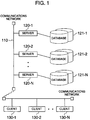
- Fig. 1 is a block diagram showing an outline of a construction of a multiserver workflow system.
- a plurality of servers 120-1 to 120-N and a plurality of clients 130-1 to 130-N are connected to a communications network 110 and databases 121-1 to 121-N are connected to the respective servers.
- the communications network 110 is an LAN (Local Area Network), a WAN (Wide Area Network), a public telephone line, an Internet, or the like.
- the server 120 and client 130 are computers such as personal computers, workstations, or the like each having a CPU, a memory, input/output devices, and an interface to the communications network.
- the database 121 can be also included in the server 120. Communications between the server 120 and client 130 and between the servers are executed using a protocol depending on the communications network 110, for example, TCP/IP.
- TCP/IP Transmission Control Protocol
- Fig. 2 is a block diagram showing a more specific structural example of the multiserver workflow system and a user interface on the client.
- server 1 120-1
- server 2 120-2
- server 3 120-3
- the server 1 belongs to an accounting business subsystem.
- the server 2 belongs to a personnel business subsystem.
- the server 3 belongs to a materials business subsystem.
- a basic screen 200 is displayed on a display device of the client X.
- Buttons of case input 201, INBOXes 211 to 214, and OUTBOXes 221 to 224 are displayed on the basic screen 200.
- the user selects the case input button 201 by a mouse click or the like. After that, a list of subsystems which can be used by the user is shown. By further selecting a desired subsystem, a business process in the selected subsystem is displayed. The subsequent operation is the same as that of the conventional workflow system of the single server construction.
- the user selects the INBOX button in order to access a case which is not processed yet and has to be processed from now on.
- the user selects the OUTBOX button in order to see a status of a case which has already been inputted or processed.
- the INBOX and OUTBOX buttons (211, 221) of all of the systems, titles of the cases relating to the user in all of the subsystems are displayed together with the additional information.
- the INBOX and OUTBOX buttons (212 - 214, 222 - 224) of each system a title of the cases relating to the user in the selected subsystem are displayed together with the additional information.
- Fig. 3 is a diagram for explaining information which is distributed to the servers of each subsystem.
- the information is made by one server and the information is distributed to each server.
- a dedicated server may be provided or any one of the servers 1, 2, and 3 constructing the business subsystems as shown in Fig. 2 may be used.
- the server which makes the information to be distributed to each server is called a management server.
- the information is made in the management server by the following procedure.
- a managing program on the management server makes a subsystem list table 310 in accordance with the input of a manager and stores the table into a memory in the management server.
- the subsystem list table 310 includes a name of the server constructing each subsystem and an address (for example, IP address) on the communications network of the server.
- the managing program on the management server makes a user information table 320 in accordance with the input of the manager and stores the table into the memory in the management server.
- the user informationtable 320 includes user IDs of all of the users who use the system, sections to which they belong, names, and posts.
- the table 320 can also further include items such as passwords, nicknames, and the like.
- the user information table may be made by the server of each subsystem and collected to the management server.
- the managing program on the management server makes a subsystem user information table 330 in accordance with the input of the manager and on the basis of the subsystem list table 310 and stores the table into the memory in the management server.
- the manager designates the users who use each subsystem by indicating a condition. For example, as shown in the table 330 in Fig. 3, the users in an operation section are designated for the subsystem of the server 1. All of the users are designated for the subsystem of the server 2. The users in the operation section and group leaders of all sections are designated for the subsystem of the server 3.
- the table 330 includes the server names and inputted conditions.
- the managing program on the management server compares the items in the user information table 320 which has already been made with the conditions in the subsystem user information table 330, determines the connectable servers for respective users, and makes a user connection information table 340.
- the user connection information has a list of the connectable servers in addition to the same items as those in the user information table 330.
- the managing program on the management server distributes the subsystem list table 310 and the user connection information table 340 to all of the servers via the communications network. Therefore, all of the servers 1 to 3 have the same information.
- the managing program is software which is executed by the CPU of the management server.
- the server to be connected in default is determined and the client has its address as default connection server information 410.
- the client connects to the default connection server and transmits a login request (430) to the connection server together with the user ID of the user who uses the client.
- the client can transmit a server information updating request or a login request to the server being connected together with the user ID at another arbitrary timings.
- the server When the login request or server information updating request is received, the server extracts the user ID included in those requests.
- the server extracts the connectable server names of the user ID from the user connection information table 340 and, further, extracts the addresses of the connectable servers from the subsystem list table 310. After that, the server transmits the connectable server names and the addresses as a connectable server list to a sending source of the login request or the server information updating request (440).
- the client stores the received connectable server list as a table 420. In some systems, a plurality of users share one client. In such system, the client may store the connectable server lists for the respective users.
- the client When the client receives the login request from the user, the client obtains information on the server which has previously been designated as a default server on own client machine (step 500) and tries to connect to the default server.
- the connectable server list table 420 is downloaded onto the own client machine (step 509). Even when the server list has already existed on the client, by again downloading, the client can obtain the new connectable server list corresponding to the login user. After that, the client starts the workflow business (step 510).
- the client checks whether the connectable server list table 420 for the user exists on the own client machine or not (step 502).
- step 502 the client tries to connect to one of the servers in the list (step 505).
- the client checks if another server exists in the list (step 507). When there is another server (YES in step 507), the client tries to connect to the server (step 505).
- the connectable server list table 420 is downloaded onto the own client machine (step 509).
- the above process is realized by software which is executed by the CPU of the client.
- the order of selecting the connection trying server in the server list table 420 by the client can be determined by the client or can be merely the topdown order of in the table.
- the basic screen 200 which is displayed on the display device of the client is shown in the paragraph (2) mentioned above and Fig. 2.
- the INBOX and OUTBOX buttons of all of the subsystems and each subsystem which can be used by the user are displayed in the above screen. This display is performed on the basis of the connectable server list table 420 on the client.
- the client obtains the address of the designated server from the server list table 420.
- the process corresponding to the designated button is started.
- the connecting process is executed by using the obtained address and, after completion of the user authentication, the process corresponding to the designated button is started.
- the client sequentially connects to all of the servers in the connectable server list table 420, receives the user authentication, and executes the transmission and reception of the information and the processes. During the process, if there is a server which is not working, the process for this server is skipped.
- the client can obtain the list of the servers which can be used by the user from any server.
- a service for accessing a plurality of servers can be provided to the user with a simple user interface.
- the numbers of items in the tables of the subsystem list, user information, subsystem user information, user connection information, and connectable server list can be increased or decreased as necessary.
Abstract
Description
Claims (9)
- A multiserver workflow system comprising:a plurality of servers (120-1, 120-2, 120-N);a plurality of clients (130-1, 130-2, 130-N); anda network (110) to which said servers and said clients are connected,wherein each of said servers and users who use the clients construct a subsystem,all of the servers have address information (310) of the servers constructing all subsystems and correspondence information (340) of all users and the subsystems which can be used by respective users, andwhen each client connects to any one of said servers, said client downloads a list of the subsystems which can be used by the user who uses said client and addresses of the servers constructing said usable subsystems from the connected server and stores the list as a connectable server list (420).
- A system according to claim 1, wherein each client provides a user interface (200) to access all of the usable subsystems with reference to said connection server list (420) and connects to the server constructing the subsystem selected by the user by using the addresses in the connectable server list.
- A system according to claim 1, wherein each client connects to the server by using the stored connectable server list (420) and, when the connection to said server fails, said client tries to connect to another server in the connectable server list.
- A method of managing information on servers and users in a multiserver workflow system including a plurality of subsystems, comprising the steps of:deciding an information management server;on said information management server, defining subsystem/server address information (310) including addresses of servers constructing all of the subsystems and user/subsystem correspondence information (340) indicating a correspondence between all of the users and the subsystems which can be used by respective users and storing the information;distributing said subsystem/server address information (310) and said user/subsystem correspondence information (340) from said information management server to all of the servers; andin each of the servers constructing the subsystems, storing said subsystem/server address information and said user/subsystem correspondence information being distributed, extracting a list of the subsystems which can be used by the user who uses said client and the addresses of the servers constructing said usable subsystems from said stored information in response to a request from the client, and transmitting the list (420) to said client.
- A method according to claim 4, wherein in said management server,information (320) on all of the users is collected,a condition (330) of the user constructing the subsystem is inputted, andsaid information on every user is compared with the condition of the user constructing said subsystem, the usable subsystem is determined for every user, and said user/subsystem correspondence information (340) is made.
- A method of connecting to a server by a client, comprising the steps of:having an address (410) of a default connection server;connecting to said default connection server at first, downloading a list of subsystems which can be used by a user who uses said client and addresses of the servers constructing said usable subsystems from the connection server, and storing the list as a connectable server list (420); andperforming the connection to the server by using the stored connectable server list at second and subsequent times, and when the connection to said server fails, the client tries to connect to another server in said connectable server list.
- A method according to claim 6, further comprising the step of:when the connection to the server succeeds, downloading the connectable server list (420) from the connection server in order to obtain latest information.
- A program storage device readable by a client machine, tangibly embodying a program of instructions executable by the client machine to perform method steps for connecting with a server machine, said method comprising the steps of:connecting to a predetermined default connection server at first, downloading a list of subsystems which can be used by a user who uses said client and addresses of servers constructing said usable subsystems from the connection server, and storing the list as a connectable server list; andconnecting to the server by using the stored connectable server list at second and subsequent times, and when the connection to said server fails, trying to connect to another server in said connectable server list.
- A server/client system comprising:a plurality of servers (120);a plurality of clients (130); anda network (110) to which said servers and said clients are connected,wherein all of the servers have address information (310) on all servers and correspondence information (340) of all users and the servers which can be used by respective users, andwhen each client is connected to any one of said servers, said client downloads a list of the servers which can be used by the user who uses said client and addresses of the servers from the connection server and stores the list as a connectable server list (420).
Applications Claiming Priority (2)
| Application Number | Priority Date | Filing Date | Title |
|---|---|---|---|
| JP34392997A JP3581779B2 (en) | 1997-11-28 | 1997-11-28 | Multi-server workflow system |
| JP343929/97 | 1997-11-28 |
Publications (3)
| Publication Number | Publication Date |
|---|---|
| EP0919912A2 true EP0919912A2 (en) | 1999-06-02 |
| EP0919912A3 EP0919912A3 (en) | 2006-07-26 |
| EP0919912B1 EP0919912B1 (en) | 2011-05-04 |
Family
ID=18365344
Family Applications (1)
| Application Number | Title | Priority Date | Filing Date |
|---|---|---|---|
| EP98122235A Expired - Lifetime EP0919912B1 (en) | 1997-11-28 | 1998-11-23 | Multiserver workflow system |
Country Status (4)
| Country | Link |
|---|---|
| US (1) | US6275846B1 (en) |
| EP (1) | EP0919912B1 (en) |
| JP (1) | JP3581779B2 (en) |
| DE (1) | DE69842251D1 (en) |
Cited By (7)
| Publication number | Priority date | Publication date | Assignee | Title |
|---|---|---|---|---|
| EP1069520A2 (en) * | 1999-07-13 | 2001-01-17 | Pfizer Products Inc. | Integrated business information system and method |
| WO2001076186A1 (en) * | 2000-03-30 | 2001-10-11 | British Telecommunications Public Limited Company | Data networks |
| WO2001091417A2 (en) * | 2000-05-19 | 2001-11-29 | Netpro Holdings, Inc. | Management and delivery of online webcasts |
| WO2001095137A2 (en) * | 2000-06-02 | 2001-12-13 | Overx, Inc. | Method and apparatus for managing data location information in a network |
| KR100377189B1 (en) * | 1999-12-24 | 2003-03-28 | 한국전자통신연구원 | System and method for data exchange between workflow system and applications |
| US7233978B2 (en) | 1998-07-08 | 2007-06-19 | Econnectix, Llc | Method and apparatus for managing location information in a network separate from the data to which the location information pertains |
| US7814169B2 (en) | 1997-01-13 | 2010-10-12 | Econnectix, Llc | System and method for establishing and retrieving data based on global indices |
Families Citing this family (15)
| Publication number | Priority date | Publication date | Assignee | Title |
|---|---|---|---|---|
| JP3681277B2 (en) * | 1998-04-24 | 2005-08-10 | 富士通株式会社 | Message processing apparatus, message management method, and recording medium recording message management program |
| US7150000B1 (en) | 1999-08-17 | 2006-12-12 | Nash Controlware, Inc. | Component development with autonomous and compiled components to implement and consume services with components operate in edit and run mode |
| US7191208B1 (en) * | 1999-12-14 | 2007-03-13 | International Business Machines Corporation | Methods of selectively distributing data in a computer network and systems using the same |
| US7467371B1 (en) * | 2000-04-28 | 2008-12-16 | Microsoft Corporation | Binding for business workflow processes |
| US7503033B2 (en) * | 2000-04-28 | 2009-03-10 | Microsoft Corporation | Model for business workflow processes |
| DE10049610A1 (en) * | 2000-10-05 | 2002-04-18 | Alcatel Sa | Network Management Client |
| US7657590B2 (en) * | 2001-02-07 | 2010-02-02 | Ubs Ag | Load balancing system and method |
| JP3743314B2 (en) * | 2001-06-28 | 2006-02-08 | 日本電気株式会社 | PC terminal connection operation system and method by mobile terminal |
| JP4039195B2 (en) * | 2001-12-27 | 2008-01-30 | 富士ゼロックス株式会社 | Network system |
| US7953087B1 (en) * | 2001-12-28 | 2011-05-31 | The Directv Group, Inc. | Content filtering using static source routes |
| US7287083B1 (en) * | 2003-03-20 | 2007-10-23 | Novell, Inc. | Computing environment failover in a branch office environment |
| JP4910274B2 (en) * | 2004-09-17 | 2012-04-04 | 富士通株式会社 | Program and server device |
| US8856276B2 (en) * | 2006-05-11 | 2014-10-07 | International Business Machines Corporation | Method, system and program product for collecting web metric data |
| US20080178164A1 (en) * | 2007-01-22 | 2008-07-24 | International Business Machines Corporation | Method, system and apparatus to associate and transform processes |
| US20100058194A1 (en) * | 2008-08-29 | 2010-03-04 | Owen James E | Remote Desktop on Multi-Function Peripheral |
Citations (2)
| Publication number | Priority date | Publication date | Assignee | Title |
|---|---|---|---|---|
| GB2308694A (en) | 1995-12-28 | 1997-07-02 | Hitachi Ltd | Arranging and removing user environments in a computer network |
| US5689708A (en) | 1995-03-31 | 1997-11-18 | Showcase Corporation | Client/server computer systems having control of client-based application programs, and application-program control means therefor |
Family Cites Families (6)
| Publication number | Priority date | Publication date | Assignee | Title |
|---|---|---|---|---|
| DE69031191T2 (en) * | 1989-05-15 | 1998-02-12 | Ibm | System for controlling access privileges |
| JPH08123744A (en) * | 1994-10-26 | 1996-05-17 | Hitachi Ltd | Work flow system |
| US5634127A (en) * | 1994-11-30 | 1997-05-27 | International Business Machines Corporation | Methods and apparatus for implementing a message driven processor in a client-server environment |
| US5754857A (en) * | 1995-12-08 | 1998-05-19 | Sun Microsystems, Inc. | Distributed asynchronous workflow on the net |
| US5774667A (en) * | 1996-03-27 | 1998-06-30 | Bay Networks, Inc. | Method and apparatus for managing parameter settings for multiple network devices |
| US6098108A (en) * | 1997-07-02 | 2000-08-01 | Sitara Networks, Inc. | Distributed directory for enhanced network communication |
-
1997
- 1997-11-28 JP JP34392997A patent/JP3581779B2/en not_active Expired - Fee Related
-
1998
- 1998-11-23 EP EP98122235A patent/EP0919912B1/en not_active Expired - Lifetime
- 1998-11-23 DE DE69842251T patent/DE69842251D1/en not_active Expired - Lifetime
- 1998-11-24 US US09/198,336 patent/US6275846B1/en not_active Expired - Fee Related
Patent Citations (2)
| Publication number | Priority date | Publication date | Assignee | Title |
|---|---|---|---|---|
| US5689708A (en) | 1995-03-31 | 1997-11-18 | Showcase Corporation | Client/server computer systems having control of client-based application programs, and application-program control means therefor |
| GB2308694A (en) | 1995-12-28 | 1997-07-02 | Hitachi Ltd | Arranging and removing user environments in a computer network |
Non-Patent Citations (2)
| Title |
|---|
| "Computer Communication Review", vol. 17, ACM, article "A yellow-pages service for a local-area network", pages: 235 - 242 |
| "Role-Based Access Control Models", IEEE COMPUTER, vol. 29, no. 2, pages 38 - 47 |
Cited By (10)
| Publication number | Priority date | Publication date | Assignee | Title |
|---|---|---|---|---|
| US7814169B2 (en) | 1997-01-13 | 2010-10-12 | Econnectix, Llc | System and method for establishing and retrieving data based on global indices |
| US7233978B2 (en) | 1998-07-08 | 2007-06-19 | Econnectix, Llc | Method and apparatus for managing location information in a network separate from the data to which the location information pertains |
| EP1069520A2 (en) * | 1999-07-13 | 2001-01-17 | Pfizer Products Inc. | Integrated business information system and method |
| EP1069520A3 (en) * | 1999-07-13 | 2005-01-26 | Pfizer Products Inc. | Integrated business information system and method |
| KR100377189B1 (en) * | 1999-12-24 | 2003-03-28 | 한국전자통신연구원 | System and method for data exchange between workflow system and applications |
| WO2001076186A1 (en) * | 2000-03-30 | 2001-10-11 | British Telecommunications Public Limited Company | Data networks |
| WO2001091417A2 (en) * | 2000-05-19 | 2001-11-29 | Netpro Holdings, Inc. | Management and delivery of online webcasts |
| WO2001091417A3 (en) * | 2000-05-19 | 2002-06-06 | Broadstream Com Inc | Management and delivery of online webcasts |
| WO2001095137A2 (en) * | 2000-06-02 | 2001-12-13 | Overx, Inc. | Method and apparatus for managing data location information in a network |
| WO2001095137A3 (en) * | 2000-06-02 | 2003-01-30 | Overx Inc | Method and apparatus for managing data location information in a network |
Also Published As
| Publication number | Publication date |
|---|---|
| EP0919912B1 (en) | 2011-05-04 |
| EP0919912A3 (en) | 2006-07-26 |
| JP3581779B2 (en) | 2004-10-27 |
| US6275846B1 (en) | 2001-08-14 |
| DE69842251D1 (en) | 2011-06-16 |
| JPH11161606A (en) | 1999-06-18 |
Similar Documents
| Publication | Publication Date | Title |
|---|---|---|
| EP0919912A2 (en) | Multiserver workflow system | |
| US20190007526A1 (en) | Provisioning multiple network resources | |
| US6868444B1 (en) | Server configuration management and tracking | |
| US7013334B2 (en) | Network system, device management system, device management method, data processing method, storage medium, and internet service provision method | |
| US7720865B2 (en) | Document management apparatus, document management method, and storage medium storing program | |
| US7295657B1 (en) | Automated selection of a backup recipient and distribution of an instant messaging request to the backup recipient | |
| EP0986225A1 (en) | System and method for securely synchronizing multiple copies of a workspace element in a network | |
| EP1014266A2 (en) | Method, apparatus and program storage device for a client and adaptive synchronization and transformation server | |
| US20020103687A1 (en) | System and method for ordering contract workers | |
| EP1217551A2 (en) | Managing a layered hierarchical data set | |
| US20030022657A1 (en) | Application provisioning over a wireless network | |
| US20060075020A1 (en) | Context administrator | |
| US20010013054A1 (en) | Server device, a method and system for communication, and a computer product | |
| US20080022195A1 (en) | System, method and program for managing electronic sticky notes | |
| JPH09198294A (en) | System performing synchronization between local area network and distributed computing environment | |
| CN110162529A (en) | A kind of data processing method, service server and data processing system | |
| US20020078104A1 (en) | Method and system for managing documents | |
| US20030233336A1 (en) | System to retate personal information to a unique identifier | |
| US20020120786A1 (en) | System and method for managing application integration utilizing a network device | |
| US7716678B2 (en) | Processing messages in a message queueing system | |
| JPH08123767A (en) | Schedule adjusting system using mail system | |
| JP3931941B2 (en) | Work process management apparatus and work process management method | |
| US20040098289A1 (en) | Operations management policy distributing method, operations management policy distributing apparatus, and operations management policy distributing program | |
| US7356712B2 (en) | Method of dynamically assigning network access priorities | |
| JP4146101B2 (en) | Knowledge accumulation support system and public summary providing method in the same system |
Legal Events
| Date | Code | Title | Description |
|---|---|---|---|
| PUAI | Public reference made under article 153(3) epc to a published international application that has entered the european phase |
Free format text: ORIGINAL CODE: 0009012 |
|
| AK | Designated contracting states |
Kind code of ref document: A2 Designated state(s): AT BE CH CY DE DK ES FI FR GB GR IE IT LI LU MC NL PT SE |
|
| AX | Request for extension of the european patent |
Free format text: AL;LT;LV;MK;RO;SI |
|
| 17P | Request for examination filed |
Effective date: 20060331 |
|
| PUAL | Search report despatched |
Free format text: ORIGINAL CODE: 0009013 |
|
| AK | Designated contracting states |
Kind code of ref document: A3 Designated state(s): AT BE CH CY DE DK ES FI FR GB GR IE IT LI LU MC NL PT SE |
|
| AX | Request for extension of the european patent |
Extension state: AL LT LV MK RO SI |
|
| RIC1 | Information provided on ipc code assigned before grant |
Ipc: H04L 29/06 20060101ALI20060616BHEP Ipc: G06F 9/46 20060101AFI19990319BHEP |
|
| 17Q | First examination report despatched |
Effective date: 20060913 |
|
| AKX | Designation fees paid |
Designated state(s): DE GB |
|
| GRAP | Despatch of communication of intention to grant a patent |
Free format text: ORIGINAL CODE: EPIDOSNIGR1 |
|
| GRAS | Grant fee paid |
Free format text: ORIGINAL CODE: EPIDOSNIGR3 |
|
| GRAA | (expected) grant |
Free format text: ORIGINAL CODE: 0009210 |
|
| AK | Designated contracting states |
Kind code of ref document: B1 Designated state(s): DE GB |
|
| REG | Reference to a national code |
Ref country code: GB Ref legal event code: FG4D |
|
| REF | Corresponds to: |
Ref document number: 69842251 Country of ref document: DE Date of ref document: 20110616 Kind code of ref document: P |
|
| REG | Reference to a national code |
Ref country code: DE Ref legal event code: R096 Ref document number: 69842251 Country of ref document: DE Effective date: 20110616 |
|
| PLBE | No opposition filed within time limit |
Free format text: ORIGINAL CODE: 0009261 |
|
| STAA | Information on the status of an ep patent application or granted ep patent |
Free format text: STATUS: NO OPPOSITION FILED WITHIN TIME LIMIT |
|
| 26N | No opposition filed |
Effective date: 20120207 |
|
| PGFP | Annual fee paid to national office [announced via postgrant information from national office to epo] |
Ref country code: DE Payment date: 20120126 Year of fee payment: 14 |
|
| REG | Reference to a national code |
Ref country code: DE Ref legal event code: R097 Ref document number: 69842251 Country of ref document: DE Effective date: 20120207 |
|
| GBPC | Gb: european patent ceased through non-payment of renewal fee |
Effective date: 20121123 |
|
| REG | Reference to a national code |
Ref country code: DE Ref legal event code: R119 Ref document number: 69842251 Country of ref document: DE Effective date: 20130601 |
|
| PG25 | Lapsed in a contracting state [announced via postgrant information from national office to epo] |
Ref country code: DE Free format text: LAPSE BECAUSE OF NON-PAYMENT OF DUE FEES Effective date: 20130601 |
|
| PG25 | Lapsed in a contracting state [announced via postgrant information from national office to epo] |
Ref country code: GB Free format text: LAPSE BECAUSE OF NON-PAYMENT OF DUE FEES Effective date: 20121123 |