EP0920969B1 - Injection molding means - Google Patents
Injection molding means Download PDFInfo
- Publication number
- EP0920969B1 EP0920969B1 EP98850181A EP98850181A EP0920969B1 EP 0920969 B1 EP0920969 B1 EP 0920969B1 EP 98850181 A EP98850181 A EP 98850181A EP 98850181 A EP98850181 A EP 98850181A EP 0920969 B1 EP0920969 B1 EP 0920969B1
- Authority
- EP
- European Patent Office
- Prior art keywords
- bushing
- front piece
- sprue
- sprue bushing
- mold
- Prior art date
- Legal status (The legal status is an assumption and is not a legal conclusion. Google has not performed a legal analysis and makes no representation as to the accuracy of the status listed.)
- Expired - Lifetime
Links
- 238000001746 injection moulding Methods 0.000 title claims description 5
- 239000000919 ceramic Substances 0.000 claims description 8
- 239000012815 thermoplastic material Substances 0.000 claims description 5
- 229910010293 ceramic material Inorganic materials 0.000 claims description 4
- 239000007769 metal material Substances 0.000 claims description 3
- 239000000463 material Substances 0.000 description 13
- 229910000831 Steel Inorganic materials 0.000 description 3
- 239000010959 steel Substances 0.000 description 3
- 238000000034 method Methods 0.000 description 2
- 239000012671 ceramic insulating material Substances 0.000 description 1
- 238000001816 cooling Methods 0.000 description 1
- 230000001351 cycling effect Effects 0.000 description 1
- 230000001419 dependent effect Effects 0.000 description 1
- 238000010438 heat treatment Methods 0.000 description 1
- 238000000465 moulding Methods 0.000 description 1
- 238000013021 overheating Methods 0.000 description 1
- 239000004033 plastic Substances 0.000 description 1
- 238000004804 winding Methods 0.000 description 1
Images

Classifications
-
- B—PERFORMING OPERATIONS; TRANSPORTING
- B29—WORKING OF PLASTICS; WORKING OF SUBSTANCES IN A PLASTIC STATE IN GENERAL
- B29C—SHAPING OR JOINING OF PLASTICS; SHAPING OF MATERIAL IN A PLASTIC STATE, NOT OTHERWISE PROVIDED FOR; AFTER-TREATMENT OF THE SHAPED PRODUCTS, e.g. REPAIRING
- B29C45/00—Injection moulding, i.e. forcing the required volume of moulding material through a nozzle into a closed mould; Apparatus therefor
- B29C45/17—Component parts, details or accessories; Auxiliary operations
- B29C45/26—Moulds
- B29C45/27—Sprue channels ; Runner channels or runner nozzles
- B29C45/2701—Details not specific to hot or cold runner channels
-
- B—PERFORMING OPERATIONS; TRANSPORTING
- B29—WORKING OF PLASTICS; WORKING OF SUBSTANCES IN A PLASTIC STATE IN GENERAL
- B29C—SHAPING OR JOINING OF PLASTICS; SHAPING OF MATERIAL IN A PLASTIC STATE, NOT OTHERWISE PROVIDED FOR; AFTER-TREATMENT OF THE SHAPED PRODUCTS, e.g. REPAIRING
- B29C45/00—Injection moulding, i.e. forcing the required volume of moulding material through a nozzle into a closed mould; Apparatus therefor
- B29C45/17—Component parts, details or accessories; Auxiliary operations
- B29C45/26—Moulds
- B29C45/27—Sprue channels ; Runner channels or runner nozzles
- B29C45/278—Nozzle tips
-
- B—PERFORMING OPERATIONS; TRANSPORTING
- B29—WORKING OF PLASTICS; WORKING OF SUBSTANCES IN A PLASTIC STATE IN GENERAL
- B29C—SHAPING OR JOINING OF PLASTICS; SHAPING OF MATERIAL IN A PLASTIC STATE, NOT OTHERWISE PROVIDED FOR; AFTER-TREATMENT OF THE SHAPED PRODUCTS, e.g. REPAIRING
- B29C45/00—Injection moulding, i.e. forcing the required volume of moulding material through a nozzle into a closed mould; Apparatus therefor
- B29C45/17—Component parts, details or accessories; Auxiliary operations
- B29C45/26—Moulds
- B29C45/27—Sprue channels ; Runner channels or runner nozzles
- B29C45/2701—Details not specific to hot or cold runner channels
- B29C2045/272—Part of the nozzle, bushing or runner in contact with the injected material being made from ceramic material
Definitions
- the present invention is for a sprue bushing for use at injection molding of thermoplastic materials with hot-runner in an equipment with sprue bushing.
- Molds of this kind may be designed with a common inlet channel, a sprue, which branches into smaller runners, one for each cavity. In order to reduce the flow length in cold steel the sprue may be substituted for by a heated sprue bushing. Further improvements may be achieved by distributing the flow of material to two or more sprue bushings in a hot channel manifold. The best result is achieved if there is a n individual sprue bushing for each single mold cavity.
- the sprue bushing may also comprise a front piece and heating means and other details.
- the temperature of the material at the inlet to the mold cavity is high enough so that the material will low into and spread within the mold cavity, without being so high that the material will be damaged.
- the temperature a the tip of the ingot will then be crucial.
- H. Bopp et al. disclose in "Heisskanalsysteme für fortune Termoplaste", Plastverarbeiter, vol. 28, no. 12, 1997, p. 649-654, an injection moulding sprue bushing with an insert made of thermally insulating ceramic material.
- the ceramic is suitable for use under high wear conditions.
- An object of the present invention is a sprue bushing which will further improve the possibilities to reduce the transfer of heat from the thermoplastic material to the material in and at the tip of the bushing. It is a further object to reduce the wear of the material of the bushing. This is achieved with a means and a sprue bushing which has the characteristics that are apparent from claim 1 and dependent claim 2.
- the sprue bushing comprises a body 1 which preferably is made from steel.
- the body 1 is mounted into the mold and is thermally insulated from it by an insulating ring 12, preferably made from ceramic material.
- the bushing extends itself downwards in the direction of the figure inwards into the mold and terminates with a front piece 3, 7 which is fixed to the bushing body 1.
- the sprue bushing is heated by an electrical element 5 which is wound around the body of the bushing and the front piece, where the pitch of the winding is varied in order to achieve the possibly best heat distribution.
- the temperature is monitored and controlled by means of a thermocouple 6.
- the front piece has at the bottom surface which faces the mold an outlet opening or inlet 13 through which the thermoplastic material is pressed into the mold cavity.
- an insert bushing 9 made from ceramic material.
- the sprue bushing and the front piece are in this case closest to mold delimited by a bottom 8 made from steel of the smallest possible goods thickness.
- the bottom 8 may be advantageous when heat is dissipated through it and the cooling of the material in the outlet opening is speeded up so that the time of the operating cycle may be reduced.
- a ceramic bushing 15 is positioned in the mold 16.
- the front piece 3 has a lower part 17 which extends itself downwards to an opening 18 in the ceramic bushing and the mold into the mold cavity.
- the front piece 3 has a small direct contact surface at the mold 16 in order to obtain support of the bushing as required.
- the ceramic bushing 15 may be extended upwards so far that there is no direct contact between metallic material of the sprue bushing/the front piece and the mold. The material flows through the front part 17 of the bushing into the channel which is defined by the inside of the ceramic bushing 15 and the lower defining surface at the tip of the front piece.
Description
- The present invention is for a sprue bushing for use at injection molding of thermoplastic materials with hot-runner in an equipment with sprue bushing.
- This method is often used for tools which have several cavities for simultaneous molding of several pieces of goods. These are usually identical but may also be of different appearance. It is desirous both to reduce the loss of material as much as possible and to attain the shortest possible cycle times. Molds of this kind may be designed with a common inlet channel, a sprue, which branches into smaller runners, one for each cavity. In order to reduce the flow length in cold steel the sprue may be substituted for by a heated sprue bushing. Further improvements may be achieved by distributing the flow of material to two or more sprue bushings in a hot channel manifold. The best result is achieved if there is a n individual sprue bushing for each single mold cavity. The sprue bushing may also comprise a front piece and heating means and other details.
- In order to keep the cycling times as short as possible and to avoid overheating of the plastic material it is desirous that the temperature of the material is maintained invariable and as low as possible. This is partly attained by the above described sprue bushings which are heated by electrical resistance elements on the outside of each bushing. The elements are so distributed over the surface that the possibly best temperature conditions are attained and control of the elements is by means of thermocouples or other temperature sensors. Further improvement is achieved by insulating the sprue bushings from surrounding metallic materials, where ceramic insulating material has proven to be suitable.
- When injection molding using the above mentioned methods it is essential that the temperature of the material at the inlet to the mold cavity is high enough so that the material will low into and spread within the mold cavity, without being so high that the material will be damaged. At the same time it is desirous to keep the temperature low so that the material will solidify rapidly inside the mold so that the product may be discarded and another cycle of operation started.
- The temperature a the tip of the ingot will then be crucial.
- H. Bopp et al. disclose in "Heisskanalsysteme für technische Termoplaste", Plastverarbeiter, vol. 28, no. 12, 1997, p. 649-654, an injection moulding sprue bushing with an insert made of thermally insulating ceramic material. The ceramic is suitable for use under high wear conditions.
- An object of the present invention is a sprue bushing which will further improve the possibilities to reduce the transfer of heat from the thermoplastic material to the material in and at the tip of the bushing. It is a further object to reduce the wear of the material of the bushing. This is achieved with a means and a sprue bushing which has the characteristics that are apparent from claim 1 and
dependent claim 2. - The invention will below be described more in detail with reference to the embodiments that are shown in the enclosed drawings.
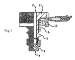
- Figure 1 shows in partial cross-section a sprue bushing. (not part of the invention).
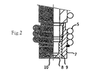
- Figure 2 shows an embodiment of the front part of the sprue bushing.
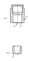
- Figure 3 shows the outer, front part of the bushing of figure 2.
- Figure 4 shows an insert to the bushing of figure 3.
- Figure 8 shows a further embodiment of the invention.
-
- All figures are in full or partial cross-section.
- The sprue bushing comprises a body 1 which preferably is made from steel. The body 1 is mounted into the mold and is thermally insulated from it by an insulating
ring 12, preferably made from ceramic material. The bushing extends itself downwards in the direction of the figure inwards into the mold and terminates with afront piece 3, 7 which is fixed to the bushing body 1. The sprue bushing is heated by anelectrical element 5 which is wound around the body of the bushing and the front piece, where the pitch of the winding is varied in order to achieve the possibly best heat distribution. The temperature is monitored and controlled by means of athermocouple 6. The front piece has at the bottom surface which faces the mold an outlet opening or inlet 13 through which the thermoplastic material is pressed into the mold cavity. - In order to further reduce the dissipation of heat to surrounding goods, increase the precision of the temperature of the material and increase the wear resistance of the sprue bushing it has, closest to the tip of the front piece at the outlet opening 13 in the embodiment of figures 2-4, an
insert bushing 9 made from ceramic material. The sprue bushing and the front piece are in this case closest to mold delimited by abottom 8 made from steel of the smallest possible goods thickness. Thebottom 8 may be advantageous when heat is dissipated through it and the cooling of the material in the outlet opening is speeded up so that the time of the operating cycle may be reduced. - In the embodiment of the invention which is shown in figure 5 a
ceramic bushing 15 is positioned in themold 16. Thefront piece 3 has alower part 17 which extends itself downwards to an opening 18 in the ceramic bushing and the mold into the mold cavity. Thefront piece 3 has a small direct contact surface at themold 16 in order to obtain support of the bushing as required. In variations of this embodiment theceramic bushing 15 may be extended upwards so far that there is no direct contact between metallic material of the sprue bushing/the front piece and the mold. The material flows through thefront part 17 of the bushing into the channel which is defined by the inside of theceramic bushing 15 and the lower defining surface at the tip of the front piece. - Other embodiments of the invention are possible within the frame of the inventive idea, especially in respect of the outer shape and the shape of the internal channel of the ceramic insert bushings. Also the tip of the sprue bushing and the front piece may be designed in various ways in order to be adapted to the ceramic inserts.
Claims (2)
- Sprue bushing for injection molding of thermoplastic material comprising a front piece and inside which there is a flow channel for the thermoplastic material, at the outlet opening of the sprue bushing/front piece and the corresponding inlet of a mold cavity there is a bushing (4, 9, 15) made from thermally insulating ceramic material which is a part of the sprue bushing/front piece and comprises a contacting surface to contact with the wall of the mold cavity characterized in that the sprue bushing/front piece is defined against the mold cavity by a bottom (8) of metallic material.
- Sprue bushing according to claim 1 characterized in that the ceramic bushing (15) is mounted into the mold (16) with at least one contacting surface to the sprue bushing/front piece (3).
Applications Claiming Priority (2)
| Application Number | Priority Date | Filing Date | Title |
|---|---|---|---|
| SE9704540A SE518906C2 (en) | 1997-12-05 | 1997-12-05 | Injection molding device |
| SE9704540 | 1997-12-05 |
Publications (2)
| Publication Number | Publication Date |
|---|---|
| EP0920969A1 EP0920969A1 (en) | 1999-06-09 |
| EP0920969B1 true EP0920969B1 (en) | 2005-03-30 |
Family
ID=20409277
Family Applications (1)
| Application Number | Title | Priority Date | Filing Date |
|---|---|---|---|
| EP98850181A Expired - Lifetime EP0920969B1 (en) | 1997-12-05 | 1998-11-30 | Injection molding means |
Country Status (4)
| Country | Link |
|---|---|
| US (1) | US6331106B1 (en) |
| EP (1) | EP0920969B1 (en) |
| DE (1) | DE69829540T2 (en) |
| SE (1) | SE518906C2 (en) |
Cited By (1)
| Publication number | Priority date | Publication date | Assignee | Title |
|---|---|---|---|---|
| EP2011621A1 (en) | 2007-07-06 | 2009-01-07 | LKM Heatlock Co Ltd | Insulating spacer for an injection mould |
Families Citing this family (13)
| Publication number | Priority date | Publication date | Assignee | Title |
|---|---|---|---|---|
| CA2358148A1 (en) | 2001-10-03 | 2003-04-03 | Mold-Masters Limited | A nozzle |
| CN100402265C (en) * | 2002-02-04 | 2008-07-16 | 标准模具有限公司 | Thermal seal between manifold and nozzle |
| ATE373557T1 (en) | 2002-07-30 | 2007-10-15 | Mold Masters Ltd | VALVE NEEDLE GUIDING AND ALIGNMENT SYSTEM FOR A HOT RUNNER IN AN INJECTION MOLDING APPARATUS |
| US7131832B2 (en) * | 2003-05-08 | 2006-11-07 | Mold-Masters Limited | Transfer seal for a removable nozzle tip of an injection molding apparatus |
| US7143496B2 (en) * | 2003-05-08 | 2006-12-05 | Mold-Masters Limited | Hot runner nozzle with removable tip and tip retainer |
| US7134868B2 (en) * | 2003-11-26 | 2006-11-14 | Mold-Masters Limited | Injection molding nozzle with wear-resistant tip having diamond-type coating |
| DE102004009806B3 (en) * | 2004-02-28 | 2005-04-21 | Otto Männer Heißkanalsysteme GmbH & Co. KG | Injection nozzle comprises an outlet for the material to be injected, a supply channel, an inlet opening, and connection elements |
| US20060041039A1 (en) * | 2004-08-20 | 2006-02-23 | Gyorgyi Fenyvesi | Fluorescent poly(alkylene terephthalate) compositions |
| KR20100075849A (en) * | 2007-09-21 | 2010-07-05 | 몰드-마스터즈(2007) 리미티드 | Injection molding nozzle having a nozzle tip with diamond crown |
| WO2009079782A1 (en) * | 2007-12-21 | 2009-07-02 | Mold-Masters (2007) Limited | Method of manufacturing hot-runner component and hot-runner components thereof |
| US7695271B2 (en) * | 2008-01-31 | 2010-04-13 | Husky Injection Molding Systems Ltd. | Non-stringing nozzle tip |
| WO2012021806A2 (en) | 2010-08-13 | 2012-02-16 | Cfph, Llc | Multi-process communication regarding gaming information |
| US9272455B2 (en) | 2014-04-30 | 2016-03-01 | Mold-Masters (2007) Limited | Hot runner system sealing arrangement |
Family Cites Families (6)
| Publication number | Priority date | Publication date | Assignee | Title |
|---|---|---|---|---|
| US4638849A (en) * | 1985-08-25 | 1987-01-27 | Vsi Corporation | Nozzle assembly for die casting apparatus |
| JPS63176119A (en) * | 1987-01-19 | 1988-07-20 | Toyota Motor Corp | Hot nozzle structure of injection molding machine |
| US5180594A (en) | 1990-04-10 | 1993-01-19 | Panos Trakas | Internally heated sprue bushing with thermally conductive sleeve |
| DE4012933A1 (en) * | 1990-04-24 | 1991-10-31 | Bosch Gmbh Robert | MACHINE AND TOOL PARTS FOR INJECTION MOLDING, EXTRUDING, EXTRUDING AND DIE CASTING |
| JP3087083B2 (en) * | 1991-03-18 | 2000-09-11 | イビデン株式会社 | Graphite mold for plastic molding |
| CA2093588C (en) * | 1993-04-07 | 2001-07-24 | Jobst Ulrich Gellert | Injection molding torpedo with shaft having ceramic central portion |
-
1997
- 1997-12-05 SE SE9704540A patent/SE518906C2/en not_active IP Right Cessation
-
1998
- 1998-11-30 DE DE69829540T patent/DE69829540T2/en not_active Expired - Fee Related
- 1998-11-30 EP EP98850181A patent/EP0920969B1/en not_active Expired - Lifetime
- 1998-12-04 US US09/205,764 patent/US6331106B1/en not_active Expired - Fee Related
Cited By (1)
| Publication number | Priority date | Publication date | Assignee | Title |
|---|---|---|---|---|
| EP2011621A1 (en) | 2007-07-06 | 2009-01-07 | LKM Heatlock Co Ltd | Insulating spacer for an injection mould |
Also Published As
| Publication number | Publication date |
|---|---|
| DE69829540D1 (en) | 2005-05-04 |
| EP0920969A1 (en) | 1999-06-09 |
| SE9704540L (en) | 1999-06-06 |
| SE518906C2 (en) | 2002-12-03 |
| DE69829540T2 (en) | 2006-05-04 |
| SE9704540D0 (en) | 1997-12-05 |
| US6331106B1 (en) | 2001-12-18 |
Similar Documents
| Publication | Publication Date | Title |
|---|---|---|
| EP0920969B1 (en) | Injection molding means | |
| US4500279A (en) | Heat pipe manifold system | |
| EP0144532B1 (en) | Injection molding system having an insulation sleeve | |
| US4345892A (en) | Injection moulding die with heavy-duty sprue bush | |
| US5776514A (en) | On-demand fast cycle mold | |
| US4954072A (en) | Electrically heated pin-point gate | |
| WO1995005276A1 (en) | Improved hot runner injection molding system | |
| US4820147A (en) | Injection molding elongated probe having integral heating element and locating means | |
| US7105123B2 (en) | Heat dissipation device for and method of dissipating heat from a manifold | |
| JPH04269520A (en) | Injection molding nozzle with tapered heating element | |
| JPH05147089A (en) | Injection molding device having heating element divided into cavity forming inserts | |
| EP0082363B1 (en) | Combination of a spacer clip and a tubular elongated injection molding heater element | |
| EP0229689B1 (en) | Plastic injection moulding system with multiple tip torpedo heater | |
| US5118280A (en) | Injection molding apparatus with integral cooling in a forward portion of the nozzle | |
| US4648833A (en) | Hot nozzle for runnerless mold | |
| CA1153523A (en) | Injection molding fixed pin gate | |
| JP2002331552A (en) | Valve gate type die device | |
| JPS6315892B2 (en) | ||
| JPS61121916A (en) | Mold for molding | |
| SU1395520A1 (en) | Hot-channel mould for making thermoplastic articles | |
| CN216544493U (en) | Flat hot nozzle, hot runner system and mould | |
| JPS6132735Y2 (en) | ||
| RU13632U1 (en) | HOT CHANNEL INJECTION FOR PRODUCTS FROM THERMOPLASTES | |
| JPH09277316A (en) | Hot runner device | |
| JP3329912B2 (en) | Molding material supply method and molding material supply nozzle |
Legal Events
| Date | Code | Title | Description |
|---|---|---|---|
| PUAI | Public reference made under article 153(3) epc to a published international application that has entered the european phase |
Free format text: ORIGINAL CODE: 0009012 |
|
| AK | Designated contracting states |
Kind code of ref document: A1 Designated state(s): DE ES FR GB IE IT NL |
|
| AX | Request for extension of the european patent |
Free format text: AL;LT;LV;MK;RO;SI |
|
| 17P | Request for examination filed |
Effective date: 19990916 |
|
| AKX | Designation fees paid |
Free format text: DE ES FR GB IE IT NL |
|
| 17Q | First examination report despatched |
Effective date: 20010410 |
|
| RAP1 | Party data changed (applicant data changed or rights of an application transferred) |
Owner name: N. HELLDIN AB |
|
| GRAP | Despatch of communication of intention to grant a patent |
Free format text: ORIGINAL CODE: EPIDOSNIGR1 |
|
| GRAS | Grant fee paid |
Free format text: ORIGINAL CODE: EPIDOSNIGR3 |
|
| GRAA | (expected) grant |
Free format text: ORIGINAL CODE: 0009210 |
|
| AK | Designated contracting states |
Kind code of ref document: B1 Designated state(s): DE ES FR GB IE IT NL |
|
| PG25 | Lapsed in a contracting state [announced via postgrant information from national office to epo] |
Ref country code: NL Free format text: LAPSE BECAUSE OF FAILURE TO SUBMIT A TRANSLATION OF THE DESCRIPTION OR TO PAY THE FEE WITHIN THE PRESCRIBED TIME-LIMIT Effective date: 20050330 |
|
| REG | Reference to a national code |
Ref country code: GB Ref legal event code: FG4D |
|
| REF | Corresponds to: |
Ref document number: 69829540 Country of ref document: DE Date of ref document: 20050504 Kind code of ref document: P |
|
| REG | Reference to a national code |
Ref country code: IE Ref legal event code: FG4D |
|
| PG25 | Lapsed in a contracting state [announced via postgrant information from national office to epo] |
Ref country code: ES Free format text: LAPSE BECAUSE OF FAILURE TO SUBMIT A TRANSLATION OF THE DESCRIPTION OR TO PAY THE FEE WITHIN THE PRESCRIBED TIME-LIMIT Effective date: 20050711 |
|
| NLV1 | Nl: lapsed or annulled due to failure to fulfill the requirements of art. 29p and 29m of the patents act | ||
| PG25 | Lapsed in a contracting state [announced via postgrant information from national office to epo] |
Ref country code: IE Free format text: LAPSE BECAUSE OF NON-PAYMENT OF DUE FEES Effective date: 20051130 |
|
| PLBE | No opposition filed within time limit |
Free format text: ORIGINAL CODE: 0009261 |
|
| STAA | Information on the status of an ep patent application or granted ep patent |
Free format text: STATUS: NO OPPOSITION FILED WITHIN TIME LIMIT |
|
| ET | Fr: translation filed | ||
| 26N | No opposition filed |
Effective date: 20060102 |
|
| REG | Reference to a national code |
Ref country code: IE Ref legal event code: MM4A |
|
| REG | Reference to a national code |
Ref country code: GB Ref legal event code: 732E |
|
| REG | Reference to a national code |
Ref country code: FR Ref legal event code: TP |
|
| PGFP | Annual fee paid to national office [announced via postgrant information from national office to epo] |
Ref country code: DE Payment date: 20081124 Year of fee payment: 11 |
|
| PGFP | Annual fee paid to national office [announced via postgrant information from national office to epo] |
Ref country code: IT Payment date: 20081125 Year of fee payment: 11 |
|
| PGFP | Annual fee paid to national office [announced via postgrant information from national office to epo] |
Ref country code: GB Payment date: 20081118 Year of fee payment: 11 |
|
| PGFP | Annual fee paid to national office [announced via postgrant information from national office to epo] |
Ref country code: FR Payment date: 20081128 Year of fee payment: 11 |
|
| GBPC | Gb: european patent ceased through non-payment of renewal fee |
Effective date: 20091130 |
|
| REG | Reference to a national code |
Ref country code: FR Ref legal event code: ST Effective date: 20100730 |
|
| PG25 | Lapsed in a contracting state [announced via postgrant information from national office to epo] |
Ref country code: FR Free format text: LAPSE BECAUSE OF NON-PAYMENT OF DUE FEES Effective date: 20091130 |
|
| PG25 | Lapsed in a contracting state [announced via postgrant information from national office to epo] |
Ref country code: DE Free format text: LAPSE BECAUSE OF NON-PAYMENT OF DUE FEES Effective date: 20100601 |
|
| PG25 | Lapsed in a contracting state [announced via postgrant information from national office to epo] |
Ref country code: GB Free format text: LAPSE BECAUSE OF NON-PAYMENT OF DUE FEES Effective date: 20091130 |
|
| PG25 | Lapsed in a contracting state [announced via postgrant information from national office to epo] |
Ref country code: IT Free format text: LAPSE BECAUSE OF NON-PAYMENT OF DUE FEES Effective date: 20091130 |