EP0920999A2 - Liquid ejecting head, head cartridge and liquid ejecting apparatus - Google Patents
Liquid ejecting head, head cartridge and liquid ejecting apparatus Download PDFInfo
- Publication number
- EP0920999A2 EP0920999A2 EP98309945A EP98309945A EP0920999A2 EP 0920999 A2 EP0920999 A2 EP 0920999A2 EP 98309945 A EP98309945 A EP 98309945A EP 98309945 A EP98309945 A EP 98309945A EP 0920999 A2 EP0920999 A2 EP 0920999A2
- Authority
- EP
- European Patent Office
- Prior art keywords
- substrate
- liquid
- heat generating
- driving
- elements
- Prior art date
- Legal status (The legal status is an assumption and is not a legal conclusion. Google has not performed a legal analysis and makes no representation as to the accuracy of the status listed.)
- Granted
Links
Images


Classifications
-
- B—PERFORMING OPERATIONS; TRANSPORTING
- B41—PRINTING; LINING MACHINES; TYPEWRITERS; STAMPS
- B41J—TYPEWRITERS; SELECTIVE PRINTING MECHANISMS, i.e. MECHANISMS PRINTING OTHERWISE THAN FROM A FORME; CORRECTION OF TYPOGRAPHICAL ERRORS
- B41J2/00—Typewriters or selective printing mechanisms characterised by the printing or marking process for which they are designed
- B41J2/005—Typewriters or selective printing mechanisms characterised by the printing or marking process for which they are designed characterised by bringing liquid or particles selectively into contact with a printing material
- B41J2/01—Ink jet
- B41J2/015—Ink jet characterised by the jet generation process
- B41J2/04—Ink jet characterised by the jet generation process generating single droplets or particles on demand
- B41J2/045—Ink jet characterised by the jet generation process generating single droplets or particles on demand by pressure, e.g. electromechanical transducers
- B41J2/05—Ink jet characterised by the jet generation process generating single droplets or particles on demand by pressure, e.g. electromechanical transducers produced by the application of heat
-
- B—PERFORMING OPERATIONS; TRANSPORTING
- B41—PRINTING; LINING MACHINES; TYPEWRITERS; STAMPS
- B41J—TYPEWRITERS; SELECTIVE PRINTING MECHANISMS, i.e. MECHANISMS PRINTING OTHERWISE THAN FROM A FORME; CORRECTION OF TYPOGRAPHICAL ERRORS
- B41J2/00—Typewriters or selective printing mechanisms characterised by the printing or marking process for which they are designed
- B41J2/005—Typewriters or selective printing mechanisms characterised by the printing or marking process for which they are designed characterised by bringing liquid or particles selectively into contact with a printing material
- B41J2/01—Ink jet
- B41J2/015—Ink jet characterised by the jet generation process
- B41J2/04—Ink jet characterised by the jet generation process generating single droplets or particles on demand
- B41J2/045—Ink jet characterised by the jet generation process generating single droplets or particles on demand by pressure, e.g. electromechanical transducers
- B41J2/04501—Control methods or devices therefor, e.g. driver circuits, control circuits
- B41J2/04528—Control methods or devices therefor, e.g. driver circuits, control circuits aiming at warming up the head
-
- B—PERFORMING OPERATIONS; TRANSPORTING
- B41—PRINTING; LINING MACHINES; TYPEWRITERS; STAMPS
- B41J—TYPEWRITERS; SELECTIVE PRINTING MECHANISMS, i.e. MECHANISMS PRINTING OTHERWISE THAN FROM A FORME; CORRECTION OF TYPOGRAPHICAL ERRORS
- B41J2/00—Typewriters or selective printing mechanisms characterised by the printing or marking process for which they are designed
- B41J2/005—Typewriters or selective printing mechanisms characterised by the printing or marking process for which they are designed characterised by bringing liquid or particles selectively into contact with a printing material
- B41J2/01—Ink jet
- B41J2/015—Ink jet characterised by the jet generation process
- B41J2/04—Ink jet characterised by the jet generation process generating single droplets or particles on demand
- B41J2/045—Ink jet characterised by the jet generation process generating single droplets or particles on demand by pressure, e.g. electromechanical transducers
- B41J2/04501—Control methods or devices therefor, e.g. driver circuits, control circuits
- B41J2/04541—Specific driving circuit
-
- B—PERFORMING OPERATIONS; TRANSPORTING
- B41—PRINTING; LINING MACHINES; TYPEWRITERS; STAMPS
- B41J—TYPEWRITERS; SELECTIVE PRINTING MECHANISMS, i.e. MECHANISMS PRINTING OTHERWISE THAN FROM A FORME; CORRECTION OF TYPOGRAPHICAL ERRORS
- B41J2/00—Typewriters or selective printing mechanisms characterised by the printing or marking process for which they are designed
- B41J2/005—Typewriters or selective printing mechanisms characterised by the printing or marking process for which they are designed characterised by bringing liquid or particles selectively into contact with a printing material
- B41J2/01—Ink jet
- B41J2/015—Ink jet characterised by the jet generation process
- B41J2/04—Ink jet characterised by the jet generation process generating single droplets or particles on demand
- B41J2/045—Ink jet characterised by the jet generation process generating single droplets or particles on demand by pressure, e.g. electromechanical transducers
- B41J2/04501—Control methods or devices therefor, e.g. driver circuits, control circuits
- B41J2/04543—Block driving
-
- B—PERFORMING OPERATIONS; TRANSPORTING
- B41—PRINTING; LINING MACHINES; TYPEWRITERS; STAMPS
- B41J—TYPEWRITERS; SELECTIVE PRINTING MECHANISMS, i.e. MECHANISMS PRINTING OTHERWISE THAN FROM A FORME; CORRECTION OF TYPOGRAPHICAL ERRORS
- B41J2/00—Typewriters or selective printing mechanisms characterised by the printing or marking process for which they are designed
- B41J2/005—Typewriters or selective printing mechanisms characterised by the printing or marking process for which they are designed characterised by bringing liquid or particles selectively into contact with a printing material
- B41J2/01—Ink jet
- B41J2/015—Ink jet characterised by the jet generation process
- B41J2/04—Ink jet characterised by the jet generation process generating single droplets or particles on demand
- B41J2/045—Ink jet characterised by the jet generation process generating single droplets or particles on demand by pressure, e.g. electromechanical transducers
- B41J2/04501—Control methods or devices therefor, e.g. driver circuits, control circuits
- B41J2/04563—Control methods or devices therefor, e.g. driver circuits, control circuits detecting head temperature; Ink temperature
-
- B—PERFORMING OPERATIONS; TRANSPORTING
- B41—PRINTING; LINING MACHINES; TYPEWRITERS; STAMPS
- B41J—TYPEWRITERS; SELECTIVE PRINTING MECHANISMS, i.e. MECHANISMS PRINTING OTHERWISE THAN FROM A FORME; CORRECTION OF TYPOGRAPHICAL ERRORS
- B41J2/00—Typewriters or selective printing mechanisms characterised by the printing or marking process for which they are designed
- B41J2/005—Typewriters or selective printing mechanisms characterised by the printing or marking process for which they are designed characterised by bringing liquid or particles selectively into contact with a printing material
- B41J2/01—Ink jet
- B41J2/015—Ink jet characterised by the jet generation process
- B41J2/04—Ink jet characterised by the jet generation process generating single droplets or particles on demand
- B41J2/045—Ink jet characterised by the jet generation process generating single droplets or particles on demand by pressure, e.g. electromechanical transducers
- B41J2/04501—Control methods or devices therefor, e.g. driver circuits, control circuits
- B41J2/0458—Control methods or devices therefor, e.g. driver circuits, control circuits controlling heads based on heating elements forming bubbles
-
- B—PERFORMING OPERATIONS; TRANSPORTING
- B41—PRINTING; LINING MACHINES; TYPEWRITERS; STAMPS
- B41J—TYPEWRITERS; SELECTIVE PRINTING MECHANISMS, i.e. MECHANISMS PRINTING OTHERWISE THAN FROM A FORME; CORRECTION OF TYPOGRAPHICAL ERRORS
- B41J2/00—Typewriters or selective printing mechanisms characterised by the printing or marking process for which they are designed
- B41J2/005—Typewriters or selective printing mechanisms characterised by the printing or marking process for which they are designed characterised by bringing liquid or particles selectively into contact with a printing material
- B41J2/01—Ink jet
- B41J2/015—Ink jet characterised by the jet generation process
- B41J2/04—Ink jet characterised by the jet generation process generating single droplets or particles on demand
- B41J2/045—Ink jet characterised by the jet generation process generating single droplets or particles on demand by pressure, e.g. electromechanical transducers
- B41J2/04501—Control methods or devices therefor, e.g. driver circuits, control circuits
- B41J2/04598—Pre-pulse
-
- B—PERFORMING OPERATIONS; TRANSPORTING
- B41—PRINTING; LINING MACHINES; TYPEWRITERS; STAMPS
- B41J—TYPEWRITERS; SELECTIVE PRINTING MECHANISMS, i.e. MECHANISMS PRINTING OTHERWISE THAN FROM A FORME; CORRECTION OF TYPOGRAPHICAL ERRORS
- B41J2/00—Typewriters or selective printing mechanisms characterised by the printing or marking process for which they are designed
- B41J2/005—Typewriters or selective printing mechanisms characterised by the printing or marking process for which they are designed characterised by bringing liquid or particles selectively into contact with a printing material
- B41J2/01—Ink jet
- B41J2/135—Nozzles
- B41J2/14—Structure thereof only for on-demand ink jet heads
- B41J2/14016—Structure of bubble jet print heads
- B41J2/14032—Structure of the pressure chamber
- B41J2/14048—Movable member in the chamber
-
- B—PERFORMING OPERATIONS; TRANSPORTING
- B41—PRINTING; LINING MACHINES; TYPEWRITERS; STAMPS
- B41J—TYPEWRITERS; SELECTIVE PRINTING MECHANISMS, i.e. MECHANISMS PRINTING OTHERWISE THAN FROM A FORME; CORRECTION OF TYPOGRAPHICAL ERRORS
- B41J2/00—Typewriters or selective printing mechanisms characterised by the printing or marking process for which they are designed
- B41J2/005—Typewriters or selective printing mechanisms characterised by the printing or marking process for which they are designed characterised by bringing liquid or particles selectively into contact with a printing material
- B41J2/01—Ink jet
- B41J2/135—Nozzles
- B41J2/14—Structure thereof only for on-demand ink jet heads
- B41J2/14016—Structure of bubble jet print heads
- B41J2/14072—Electrical connections, e.g. details on electrodes, connecting the chip to the outside...
-
- B—PERFORMING OPERATIONS; TRANSPORTING
- B41—PRINTING; LINING MACHINES; TYPEWRITERS; STAMPS
- B41J—TYPEWRITERS; SELECTIVE PRINTING MECHANISMS, i.e. MECHANISMS PRINTING OTHERWISE THAN FROM A FORME; CORRECTION OF TYPOGRAPHICAL ERRORS
- B41J2/00—Typewriters or selective printing mechanisms characterised by the printing or marking process for which they are designed
- B41J2/005—Typewriters or selective printing mechanisms characterised by the printing or marking process for which they are designed characterised by bringing liquid or particles selectively into contact with a printing material
- B41J2/01—Ink jet
- B41J2/135—Nozzles
- B41J2/14—Structure thereof only for on-demand ink jet heads
- B41J2/14016—Structure of bubble jet print heads
- B41J2/14153—Structures including a sensor
-
- B—PERFORMING OPERATIONS; TRANSPORTING
- B41—PRINTING; LINING MACHINES; TYPEWRITERS; STAMPS
- B41J—TYPEWRITERS; SELECTIVE PRINTING MECHANISMS, i.e. MECHANISMS PRINTING OTHERWISE THAN FROM A FORME; CORRECTION OF TYPOGRAPHICAL ERRORS
- B41J2/00—Typewriters or selective printing mechanisms characterised by the printing or marking process for which they are designed
- B41J2/005—Typewriters or selective printing mechanisms characterised by the printing or marking process for which they are designed characterised by bringing liquid or particles selectively into contact with a printing material
- B41J2/01—Ink jet
- B41J2/135—Nozzles
- B41J2/14—Structure thereof only for on-demand ink jet heads
- B41J2002/14354—Sensor in each pressure chamber
-
- B—PERFORMING OPERATIONS; TRANSPORTING
- B41—PRINTING; LINING MACHINES; TYPEWRITERS; STAMPS
- B41J—TYPEWRITERS; SELECTIVE PRINTING MECHANISMS, i.e. MECHANISMS PRINTING OTHERWISE THAN FROM A FORME; CORRECTION OF TYPOGRAPHICAL ERRORS
- B41J2/00—Typewriters or selective printing mechanisms characterised by the printing or marking process for which they are designed
- B41J2/005—Typewriters or selective printing mechanisms characterised by the printing or marking process for which they are designed characterised by bringing liquid or particles selectively into contact with a printing material
- B41J2/01—Ink jet
- B41J2/135—Nozzles
- B41J2/14—Structure thereof only for on-demand ink jet heads
- B41J2002/14379—Edge shooter
-
- B—PERFORMING OPERATIONS; TRANSPORTING
- B41—PRINTING; LINING MACHINES; TYPEWRITERS; STAMPS
- B41J—TYPEWRITERS; SELECTIVE PRINTING MECHANISMS, i.e. MECHANISMS PRINTING OTHERWISE THAN FROM A FORME; CORRECTION OF TYPOGRAPHICAL ERRORS
- B41J2202/00—Embodiments of or processes related to ink-jet or thermal heads
- B41J2202/01—Embodiments of or processes related to ink-jet heads
- B41J2202/17—Readable information on the head
-
- B—PERFORMING OPERATIONS; TRANSPORTING
- B41—PRINTING; LINING MACHINES; TYPEWRITERS; STAMPS
- B41J—TYPEWRITERS; SELECTIVE PRINTING MECHANISMS, i.e. MECHANISMS PRINTING OTHERWISE THAN FROM A FORME; CORRECTION OF TYPOGRAPHICAL ERRORS
- B41J2202/00—Embodiments of or processes related to ink-jet or thermal heads
- B41J2202/01—Embodiments of or processes related to ink-jet heads
- B41J2202/21—Line printing
Definitions
- the present invention relates to a liquid ejecting head for ejecting a desired liquid using generation of a bubble created by application of thermal energy to the liquid, a head cartridge and a liquid ejecting apparatus which use the liquid ejecting head.
- the present invention is applicable to various apparatus such as a printer, a copying machine, a facsimile machine having a communication system, a word processor having a printer portion, or a printing apparatus, for industrial use, combined with various processing devices, which effect recording on recording materials such as paper, thread, fiber, textile, leather, metal, plastic resin material, glass, wood, ceramic material or the like.
- recording means recording of image having any sense such as letters, figures or the like, and recording of patterns not having particular sense.
- An ink jet recording method or so-called bubble jet recording method is known wherein state change resulting in abrupt volume change is caused in the ink (generation of a bubble) by application of energy such as heat to the ink, and by the force provided by the state change, the ink is ejected from an ejection outlet, and is deposited on the recording material.
- a recording device using the bubble jet recording method generally comprises an ejection outlet for ejecting ink, an ink flow path in fluid communication with the ejection outlet, and an electrothermal transducer, as energy generating means, for ejecting the ink in the ink flow path, as disclosed in U. S. Patent No. 4, 723, 129, for example.
- Such a recording method is capable of printing high quality image at high speed and with low noise; the printing or recording head using the recording method, the ejection outlets for ejecting the ink can be arranged at high density, and therefore, high resolution image and particularly color image can be easily printed with small size machine.
- the bubble jet recording method is recently used widely for printers, copying machines, facsimile machine machines or other office equipment, and even for industrial systems such as textile printing apparatus or the like.
- the electrothermal transducer for generating energy for ejecting the ink can be manufactured through a semiconductor manufacturing process. Therefore, a conventional head using the bubble jet technique, comprises an element substrate (silicon substrate), electrothermal transducer formed thereon, and a groove for forming an ink flow path is formed thereon, and a top plate of resin material such as polysulfone or the like or glass or the like is combined thereon.
- element substrate is a silicon substrate
- a driver for driving the electrothermal transducers and a temperature sensor used to control the electrothermal transducers in accordance with the temperature of the head and a drive control portion or the like may be formed on the element substrate.
- Figure 20 shows an example of such a structure of the element substrate
- the element substrate 1001 is provided with heater array 1002 having a plurality of parallel electrothermal transducers for applying thermal energy for ink ejection, a driver circuit 1003 for driving the electrothermal transducers, image data transfer circuit 1004 for parallel transfer of the image data inputted serially from outside to a driver circuit 1003, and an input contact 1007 for inputting the image data and various signals or the like from outside.
- the element substrate 1001 is provided with a temperature sensor for sensing a temperature of the element substrate 1001, a resistance sensor for sensing a resistance value of the electrothermal transducers, or another sensor 1006, and a drive control portion 1005 for driving the sensor 1006 and for controlling a width of the driving pulse for the electrothermal transducers in accordance with an output from the sensor 1006.
- a head having the driver, the temperature sensor and the drive control portion on the element substrate has been put in practical use, with high reliability of the recording head and small size.
- the size of the element substrate is bulky with the result of bulky head.
- the ejection outlets are arranged at a high density such as 600dpi or 1200dpi or higher, precise alignment is required between the electrothermal transducers and ink flow paths, and the difference in the thermal-expansion between the element substrate and the top plate resulting from the heat during the driving of the electrothermal transducers, is not negligible.
- a liquid ejection head comprising a plurality of ejection outlets for ejecting liquid; a first substrate and a second substrate for constituting a plurality of liquid flow paths in fluid communication with said ejection outlets, respectively when combined with each other; a plurality of energy conversion elements disposed in said liquid flow paths, respectively to convert electrical energy to ejection energy for the liquid in said liquid flow paths; a plurality of elements or electric circuits having different functions for controlling driving conditions of said energy conversion elements; wherein said elements and electric circuits are provided either on said first substrate and said second substrate, depending on their functions.
- the elements or the electric circuits are not concentrated on one of the substrates, so that liquid ejecting head is downsized.
- the electrical connection with the outside are not effected by each of the function element and the electric circuit, but an outer contact for electrical connection of the element or the electric circuit with the outside is provided on either one of the first substrate and the second substrate, and the outer contact electrically connects the elements or electric circuits with outside on either one of the first substrate or second substrate, and a connection electrode for electrical connection of the elements or electric circuits on such surfaces of the first substrate and second substrate as are opposed to each other, so that they are electrically connected by combining the first substrate and the second substrate Since the connection with the outside is concentrated on one of the substrates, further downsizing can be accomplished.
- the selection may be such that such an element or electric circuit of all of the elements or electric circuits as are electrically connected to said energy conversion elements on individual or group basis, is provided on such one of the substrates as is provided with the energy conversion elements, and the other element or electric circuit is provided on the other substrate.
- the number of electrical connections between the first substrate and the second substrate decreases so that liability of defective connection can be reduced.
- Such an element or electric circuit of all of the elements or electric circuits as are electrically connected to the energy conversion elements on individual or group basis may include drivers for driving said energy conversion elements. With the use of the feature that external connection contacts are provided only on one substrate, further downsizing is accomplished.
- the element or the electric circuit can be manufactured through a semiconductor wafer processing technique. Because the first substrate and the second substrate are made of the same materials, the deviation therebetween due to thermal-expansion difference can be avoided. Therefore, the second object can be accomplished.
- At least the second substrate may be provided with a temperature sensor, a limitation circuit for limiting or stopping driving of the heat generating resistor in accordance with an output of the temperature sensor, so that difference of the temperature propagation depending on the presence or absence of the ink in the head, and the driving of the heat generating resistor can be limited or stopped on the basis of result thereof.
- the third object can be accomplished.
- each of said liquid flow paths may be provided with a movable member disposed faced to the energy conversion element and having a free end at a downstream side with respect to liquid flow toward then ejection outlet.
- Figure 1 is a sectional view, taken along a line parallel with a liquid flow path, of a liquid ejecting head according to an embodiment of the present invention.
- the liquid ejecting head comprises an element substrate 1 on which a plurality of heat generating elements 2 (only one of them is shown in Figure 1) for applying thermal energy for generating bubbles to liquid are disposed in parallel, a top plate 3 connected to the element substrate 1, an orifice plate 4 connected to the leading edge surface of the top plate 3, and a movable member 6 placed in a liquid flow path 7 constituted by the element substrate 1 and the top plate 3.
- the element substrate 1 comprises a substrate of silicon or the like, a silicon oxide film or silicon nitride film thereon for electric insulation and heat accumulation, and an electric resistance layer (heat generating element 2) and wiring patterned thereon.
- the electric resistance layer is supplied with a voltage through the wiring to supply the current to the electric resistance layer, so that heat generating element 2 generates heat.
- the top plate 3 cooperates to constitute liquid flow paths 7 corresponding to the heat generating elements 2, respectively, and a common liquid chamber 8 for supplying the liquid to the liquid flow paths 7, and it includes integral side walls extending from the top between the heat generating elements 2.
- the top plate 3 is a silicon material, and is manufactured by etching the liquid passage pattern and the common liquid chamber pattern, or by overlying on the silicon substrate silicon nitride material, silicon oxide or the like through known CVD method or the like to constitute the side walls, and then etching the liquid passage portions.
- the orifice plate 4 is provided with ejection outlets 5 which are formed corresponding respective liquid passages and which are in fluid communication with the common liquid chamber 8 through the liquid passages.
- the orifice plate 4 is of silicon material too, and is manufactured by machining a silicon substrate having ejection outlets 5 into a thickness of approx. 10-150 ⁇ m.
- the orifice plate 4 is not an inevitable element, and in place of the provision thereof, a wall of a thickness corresponding to the orifice plate 4 may be caused to remain at the end surface of the top plate 3 when the liquid flow path is formed in the top plate 3, and the ejection outlets 5 may be formed in the remaining portion.
- the movable member 6 separates the liquid flow path 7 to a first liquid flow path 7a in fluid communication with the ejection outlet 5 and a second release path 7 b having a heat generating element 2, and is disposed opposed to the heat generating element 2. It is in the form of a thin film cantilever of silicon material such as silicon nitride, silicon oxide or the like.
- the movable member 6 has a fulcrum 6a at an upstream with respect to a major liquid flow from the common liquid chamber 8 to the ejection outlet 5 via movable member 6 upon the liquid ejecting operation and has a free end 6b downstream of the fulcrum 6a, and it is extended as if it covers the heat generating element 2 with a predetermined distance from the heat generating element 2.
- the space between the heat generating element 2 and the movable member 6 is a bubble generating region 10.
- the pressure propagation of the bubble is directed toward the downstream side, so that pressure of the bubble is directly and therefore effectively used for the liquid ejection.
- the direction of the bubble expansion per se is similarly directed to the downstream side, and therefore, the bubble expands more in the downstream side than in the upstream side.
- the expansion direction per se of the bubble is controlled by the movable member to control the pressure propagating direction of the bubble, so that fundamental ejection properties such as the ejection efficiency, ejection power the ejection speed and/or the like.
- the bubble collapse process the bubble collapses rapidly synergetically with the elastic force of the movable member 6, and the movable member 6 finally restores to the initial position indicated by the solid line in Figure 1.
- the liquid flows into the liquid flow path 7 from the upstream, more particularly, from the common liquid chamber 8 to compensate for the contraction volume of the bubble in the bubble generating region 10 or to compensate for the amount of the ejected liquid (refilling of the liquid).
- the refilling is efficient because of the restoring function of the movable member 6.
- the liquid ejecting head of this embodiment comprises circuits and elements for driving the heat generating element 2 or controlling the driving.
- the circuits and the element are not concentrated on one of the element substrate 1 and the top plate 3, but are allotted to them on the basis of the functions. Since the element substrate 1 and the top plate 3 are of silicon material, the circuits and the elements can be easily and finely formed through semiconductor wafer processing technique.
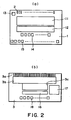
- Figure 2 illustrates a circuit structure of the liquid ejecting head shown in Figure 1, wherein (a) is a top plan view of the element substrate, (b) is a top plan view of the top plate. In Figure 2, (a) and (b) show the opposing sides.
- the element substrate 1 is provided with a plurality of heat generating elements 2 arranged in parallel with each other, drivers 11 for driving the heat generating elements 2 in accordance with the image data, an image data transfer portion 12 for supplying the inputted image data to the driver 11 and a sensor 13 for measuring a parameter necessary for controlling the driving condition for the heat generating element 2.
- the image data transfer portion 12 comprises a shift register for outputting the image data supplied in series, to the drivers 11, in parallel, and a latching circuit for storing temporarily the data outputted from the shift register.
- the image data transfer portion 12 may output the image data to the respective heat generating elements 2 or may output the image data for respective blocks of heat generating elements 2 into which the heat generating element 2 are grouped.
- the sensor 13 may be a temperature sensor for sensing the temperature adjacent to the heat generating element 2, or a resistance sensor or the like for monitoring the resistance value of the heat generating element 2.
- the ejection amount of the ejected droplet is mainly dependent on the generated bubble volume of the liquid.
- the generated bubble volume of the liquid is dependent on the temperature of the heat generating element 2 and the portion therearound. Therefore, the temperature of the heat generating element 2 and the temperature therearound are measure, and a pulse of such a small energy as is insufficient for liquid ejection(preheating pulse) is applied before application of a beating pulse for liquid ejection, and the pulse width or the output timing of the preheating pulse is changed in accordance with the output of the sensor, so that temperature of the heat generating element 2 and the temperature therearound is adjusted to assure that constant droplets are ejected, thus maintaining the image quality.
- the energy necessary for the bubble generation is represented by a required energy per unit area of the heat generating element 2 multiplied by an area of the heat generating element 2, if the heat radiation condition is constant.
- the voltage between the opposite ends of the heat generating element 2, the current flowing through the heat generating element 2 and the pulse width thereof, are selected to provide the necessary energy.
- the voltages applied to the heat generating elements 2 can be maintained substantially constant by supply it from the voltage source of the main assembly of the liquid ejecting apparatus.
- the resistance values of the heat generating elements 2 may be different depending on the lots of the element substrates 1 and individual element substrates 1, because of the variation or the like of the film thicknesses of the heat generating element 2 in the manufacturing process.
- the pulse width applied to the heat generating element 2 is constant, and the resistance value of the heat generating element 2 is larger than the design value, the current is lower, with the result of insufficiency of the supplied energy, so that bubble generation cannot be proper.
- the resistance value of the heat generating element 2 is smaller, the current is larger even when the voltage is the same. In this case, the heat generating element 2 is supplied with excessive energy, with the possible result of damage to, or service life reduction of, the heat generating element 2. Therefore, there is a method wherein the resistance values of the heat generating elements 2 are always monitored by the resistance sensor, and the power source voltage or the heating pulse width is changed in accordance with the resistance value so that heat generating elements 2 are supplied with substantially constant energy.
- the top plate 3 is provided with grooves 3a, 3b for constituting the liquid flow paths and the common liquid chamber, as described hereinbefore, and further comprises a sensor driver 17 for driving the sensor 13 provided on the element substrate 1, and a heat generating element controller 16 for controlling the driving condition for the heat generating element 2 in accordance with the output of the sensor driven by the sensor driver 17.
- the top plate 3 is provided with a supply port 3c in fluid communication with the common liquid chamber to permit supply of the liquid into the common liquid chamber for the outside.
- the stations of the element substrate 1 and the top plate 3 which are opposed to each other when they are connected, are provided with contact pads 14, 18 for electrical connection between the circuits and the like provided on the element substrate 1 and the circuits and the like provided on the top plate 3.
- the element substrate 1 is provided with an outer or external contact pad 15 functioning as input contacts for receiving external electric signals.
- the size of the element substrate 1 is larger than that of the top plate 3, and the external contact pad 15 is extended out of the top plate 3 wen the element substrate 1 and the top plate 3 are connected.
- the circuits which constitutes the driver 1L, the image data transfer portion 12 and the sensor 13 are first formed on the silicon substrate through a semiconductor wafer processing technique. Subsequently, as described, hereinbefore, the heat generating element 2 is formed, and finally, the contact pad 14 and the external contact pad 15 are formed.
- the circuits constituting the heat generating element controller 16 and the sensor driver 17 are formed on the silicon substrate by a semiconductor wafer processing technique. Then, as described hereinbefore, the grooves 3a, 3b constituting, the liquid flow paths and the common liquid chamber and the supply port 3c are formed by film,formation and etching, and finally, the connection contact pad 18 are provided.
- the thus constituted element substrate 1 and the top plate 3 are aligned and coupled, by which the heat generating elements 2 are aligned with the liquid flow paths, and the circuits and the like of the element substrate 1 and the top plate 3 are electrically connected with each other through the pads 14, 18.
- gold bumps are placed on the pads 14, 18, although doing so is not inevitable.
- the liquid ejecting head of this embodiment comprises the movable member 6, and therefore, the movable member 6 is placed on the element substrate 1 before the element substrate 1 and the connection is joined with each other.
- the orifice plate 4 is connected to the front side of the liquid flow path 7, so that liquid ejecting head 21 ( Figure 3) is provided.
- the liquid ejecting head 21 When the liquid ejecting head 21 thus manufactured is installed in the liquid ejecting apparatus or is mounted to the head cartridge which will be described hereinafter, the liquid ejecting head 21 is fixed on a base substrate 22 having a print wiring substrate 23 as shown in Figure 3, so as to constitute a liquid ejecting head unit 20.
- the print wiring substrate 23 is provided with a plurality of wiring patterns 24 for electrical connection with the head controller of the liquid ejecting apparatus, and the wiring patterns 24 are electrically connected with the outer contact pads 15 through the bonding wire 25.
- the outer contact pads 15 are provided only on the element substrate 1, and therefore, the electrical connection between the liquid ejecting head 21 and the outside can be established in the same manner as in a conventional liquid ejecting head.
- the external contact pads 15 are provided on the element substrate 1, but they may be provided on only on the top plate 3 not on the element substrate 1.
- the various circuits for driving and controlling the heat generating element 2 are distributed to the element substrate 1 and to the top plate 3 in consideration of the electrical connection between the first and second substrates, so that circuits are not concentrated on one substrate, and therefore, the liquid ejecting head can be downsized.
- element substrate 1 and the top plate 3 are both made of the silicon base material, thermal expansion coefficients of the element substrate 1 and the top plate 3 are the same. As a result, even if the thermal-expansion occurs in the element substrate 1 and the top plate 3, they keep the alignment therebetween, and therefore, the alignment between the respective heat generating elements 2 and the liquid flow paths 7.
- the circuits are divided into an element substrate groups and a top plate group depending on the functions thereof. The criteria of the grouping will be described.
- the circuit or circuits corresponding to the individual heat generating elements 2 or to blocks of the heat generating elements 2 through electric wiring, are formation d on the element substrate 1.
- the drivers 11 and the image data transfer portion 12 are those circuits. Since the heat generating elements 2 receive the driving signals in parallel, the wiring is required for the number of the signals. If such a circuit is formed on the top plate 3, the number of electric connections between the element substrate 1 and the top plate 3 is large with the result of higher liability of the connection defect, but the liability can be reduced by providing those circuits on the element substrate 1.
- the analog circuit or circuits such as a control circuit, is provided on the top plate 3 not having the heat generating element 2, since it is easily influenced by heat.
- the heat generating element controller 16 is this circuit.
- the sensor 13, may be provided either one of the element substrate 1 and the top plate 3, as desired.
- it is a resistance sensor, it is desirable to provide it on the element substrate 1 to assure the measurement accuracy.
- it is a temperature sensor, it is preferable to provide it on the element substrate 1 (first substrate) when it is for detecting the temperature rise due to abnormality of the heater driving circuit; and when it is for discriminating the state of the ink using the temperature rise of the ink, it is preferable to provide it on the top plate 3 (second substrate) or on each of the element substrate and the top plate.
- circuits such as a circuit not corresponding to the heat generating elements 2 or blocks of the heat generating elements 2 through electric wiring, a circuits not required to be provided on the element substrate 1, a sensor or the like of which the measurement accuracy is not influenced, may be provided on either one of the element substrate 1 and the top plate 3 so as to avoid concentration on one of them.
- the sensor driver 17 is this type of circuit.
- circuits and the sensors By distributing the circuits and the sensors on the basis of the criteria described above, they can be distributed with good balance without minimizing the number of electrical connections between the element substrate 1 and the top plate 3.
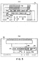
- Figure 4 shows an example of the circuit structures on the element substrate and the top plate in which the applied energy to the heat generating element is controlled in accordance with the sensor output.
- heat generating elements 32 arranged in a line, power transistors 41 functioning as drivers, AND circuits 39 for controlling the driving of the power transistors 41, a drive timing control logic circuit 38 for controlling the drive timing of the power transistors 41, an image data transfer circuit 42 comprising the shift registers and latching circuits, and a sensor 43 for detecting the resistance value of the heat generating element 32.
- the drive timing control logic circuit 38 functions for divided drive of the heat generating elements 32 (the electric power is not supplied simultaneously to all of the heat generating element 32) to reduce the capacity of the voltage source of the apparatus, and an enabling signal for driving the drive timing control logic circuit 38 is supplied through enabling signal input contacts 45k-45n which are external or outer contact pads.
- the outer contact pads provided on the element substrate 31 include an input contact 45a for supplying electric energy to the heat generating elements 32, a grounding contact 45b for the power transistors 41, input contacts 45c-45e for the signal necessary for controlling the energy driving the heat generating elements 32, a driving voltage source contact 45f for the logic circuit, a grounding contact 45g, an input contact 45i for the serial data to be supplied to the shift register of the image data transfer circuit 42, an input contact 45h for a serial clock signal in synchronization therewith, and an input contact 45j for a latch Clock signal to be supplied to the latching circuit.
- a sensor driving circuit 47 for driving the sensor 43 On the top plate 33 are formed a sensor driving circuit 47 for driving the sensor 43, a driving signal control circuit 46 for monitoring the output of the sensor 43 and for controlling the applied energy to the heat generating elements 32 in accordance with outputs of the sensor 43, memory 49 for storing, as head information, the resistance value data sensed by the sensor 43 or a coded rank values of the resistance value data, and the liquid ejection amount properties of the heat generating elements 32 which are measured beforehand (the liquid ejection amounts with a predetermined pulse application under a predetermined temperature) and for outputting the information to the driving signal control circuit 46.
- the element substrate 31 and the top plate 32 are provided with contacts 44g, 44h, 48g, 48h for connection between the sensor 43 and the sensor driving circuit 47, contacts 44b-44d, 48b-48d for connection between the input contacts 45c-45e and the driving signal control circuit 46, and a contact 48a for inputting the output of the driving signal control circuit 46 into one of the input contacts of the AND circuit 39, as shown in the Figure.
- the resistance value of the heat generating element 32 is detected by the sensor 43, and the results thereof are stored in the memory 43.
- the driving signal control circuit 46 determines rising and falling data for the driving pulse for the heat generating element 32 in accordance with the resistance value data and the liquid ejection amount property stored in the memory 43, and supplies the determined data to the AND circuit 39 through the contacts 48a, 44a.
- the image data inputted in series are stored in a shift register of the image data transfer circuit 42, and are latched in the latching circuit by a latching signal, and is supplied to the AND circuit 39 through the drive timing control circuit 38.
- the pulse width of the heating pulse is determined in accordance with the rising and falling data, and the heat generating element 32 is actuated with the pulse width.
- the heat generating element 32 is supplied with a substantially constant energy.
- the senor 43 is a resistance sensor. It may be a temperature sensor for detecting a degree of heat accumulation of the heat generating element 32 or for detecting a temperature of the element substrate 31, and the preheating pulse width may be controlled in accordance with the output of the temperature sensor.
- the driving signal control circuit 46 determines the preheat width of the heat generating element 32 in accordance with the liquid ejection amount property determined beforehand and the temperature data detected by the sensor 43, after the voltage source of the liquid ejecting apparatus is actuated.
- the memory 49 stores selection data for selecting preheat widths corresponding to the respective heat generating elements 32, and when the preheat is actually effected, the preheating signal is selected in accordance with the selection data stored in the memory 49; and then, the heat generating elements 32 are preheated in accordance therewith. In such a manner, the preheating pulse is so selected and applied that ejection amounts of the respective ejection outlets are uniform irrespective of the temperature state.
- the selection data which determine the preheat width may be once stored at the time of the start of the liquid ejecting apparatus.
- one sensor 43 is used, but two sensors (resistance sensor and temperature sensor) may be provided, and both of the heating pulse and the preheating pulse are controlled in accordance with the respective outputs, by which the image quality can be further improved.
- the head information stored in the memory 49 may include a nature of the liquid to be ejected (when the liquid is ink, the nature may be the color of the ink or the like) in addition to the resistance value data of the heat generating elements. This is because, the properties of the liquids may be different, and therefore, the ejection properties are different.
- the head information may be stored in the memory 49 after the liquid ejecting head is assembled as non-volatile memory, or the information may be supplied from the apparatus after installation of the liquid ejecting apparatus loaded with the liquid ejecting head.
- the senor 43 is provided on the element substrate 31, but when the sensor 43 is a temperature sensor, it may be provided on the top plate 33. As regards the memory 49, it may be provided on the element substrate 31 not on the top plate 33 if the element substrate 31 has enough space.
- the liquid may not be ejected despite the liquid is in the common liquid chamber, if bubbles exist in the common liquid chamber and are introduced to the liquid flow paths with the refilling of the liquid.
- a sensor may be provided to detect the presence or absence of the liquid in each of the liquid flow path (particularly, adjacent the heat generating element 32) (detail thereof will be described hereinafter), and when the absence of the liquid may be detected by the sensor, the event may be supplied to the outside.
- a process circuit for this purpose may be provided on the top plate 33.
- the liquid in the liquid ejecting head is forcedly sucked out through the ejection outlets by the liquid ejecting apparatus in response to the output of the process circuit, by which the bubble in the liquid flow path can be removed.
- the senor for detecting the presence or absence of the liquid may effect the detection using the change of the resistance value through the liquid or using an abnormal temperature rise of the heat generating element in the absence of the liquid.
- Figure 5 shows an example of circuit structures on the element substrate and the top plate for controlling the temperature of the element substrate in accordance with a sensor output.
- a temperature keeping heater 55 for heating the element substrate 51 per se to control the temperature of the element substrate 51 in addition to the heat generating elements 52 for the liquid ejection, and a power transistor 56 as a driver for the temperature keeping heater 55, as compared with the element substrate 31 shown in Figure 4, (a).
- the sensor 63 is a temperature sensor for measuring the temperature of the element substrate 51.
- the temperature keeping heater control circuit 66 includes a comparator which compares an output of the sensor 63 with a threshold predetermined on the basis of the temperature required for the element substrate 51, and when the output of the sensor 63 is higher than the threshold, a temperature keeping heater control signal for driving the temperature keeping heater 55 is outputted.
- the temperature required for the element substrate 51 is such a temperature with which the viscosity of the liquid in the liquid ejecting head is within a stable ejection range.
- Contacts 64a, 68a for inputting a temperature keeping heater control signal outputted from the temperature keeping heater control circuit 66 to the power transistor 56 for the temperature keeping heater formed on the element substrate 51, are provided on the element substrate 51 and the top plate 53 as contact pads.
- the structures in the other respect is the same as those shown in Figure 4, and therefore, the detailed explanation is omitted for simplicity.
- the temperature keeping heater 55 is actuated by the temperature keeping heater control circuit 66 in accordance with the output of the sensor 63, so that temperature of the element substrate 51 is maintained at a predetermined temperature.
- the viscosity of the liquid in the liquid ejecting head is maintained within a stable ejection range, thus assuring proper ejection.
- a correction value for compensating the variation may be stored in the memory 69 as head information, and the threshold set in the temperature keeping heater control circuit 66 may be adjusted in accordance with the correction value stored in the memory 69.
- the grooves constituting the liquid flow paths 7 are formed in the top plate 3, and the movable members 6 are manufactured in a process separate from that for the element substrate 1, and the member provided with the ejection outlets 5 ((orifice plate 4) is made of a member separate from the element substrate 1 and from the top plate 3.
- the present invention is not limited to this case.
- Figures 6-10 show another example of the element substrate and the top plate.
- the example of Figures 4 and 5 is applicable to the liquid ejecting heads according to the embodiments of Figures 6-10, which will be described.
- the structure of the liquid ejecting head is taken, and the structure of the electric circuits are omitted for simplicity.
- the movable members 76 are built in the element substrate 71, and the top plate 3 is provided with the ejection outlets 75.
- the movable member 76 is directly formed on the element substrate 71 through a film formation process after the heat generating element 72 is formed on the element substrate 71. At this time, the upper part of the heat generating element 72 is treated for weakening the contact, by which the movable member can be formed into a cantilever.
- top plate 73 when the grooves constituting the liquid flow paths 77 and the common liquid chamber 78 are formed in the top plate 73, a wall having a thickness of the orifice plate is caused to remain at the end surface of the top plate 73, and the ejection outlets 75 are formed through the wall by ion beam machining, electron beam process or the like.
- the grooves constituting the liquid flow paths 87 and common liquid chamber 88 are formed in the element substrate 81, and the top plate 83 has a supply port 83c only as opening.
- the movable members 86 are formed on the element substrate 81.
- the material comprising as a main material silicon material such as silicon nitride, silicon oxide or the like is formed into a film on the element substrate 81, and then, the portions of the walls corresponding to the orifice plate and the side walls 89 of the flow paths, are patterned. Subsequently, similarly to Figure 6, ejection outlets 85 are formed, and finally, the top plate 83 is connected.
- the heat generating elements 82, the liquid flow paths 87, the movable members 86 are all formed using semiconductor wafer processing technique, and the ejection outlets 85 are formed by patterning, so that liquid flow paths are provided with high accuracy.
- Accuracy of the fastening of the top plate 83 is dependent on the machine assembling accuracy, but what is done is to connect the supply ports 83c with the liquid flow paths 87, and the ejection performance is determined by the liquid flow passage configurations, and therefore, a less expensive assembling machine is enough for the desired accuracy.
- the liquid ejecting head is an ordinary one not having the movable member, and the structure thereof is the same as that of Figure 1 in the other respects. More particularly, grooves constituting the liquid flow paths 97 and the common liquid chamber 88 are formed in the element substrate 91 having the heat generating elements 92 formed thereon, and the top plate 93 having the supply port 93c formed therein is fastened thereto, and then, an orifice plate 94 having the ejection outlets 95 formed therein is connected or fastened to the front end of the united element substrate 91 and top plate 93.
- the ejection outlets 115 are formed in the element substrate 111.
- the structure of the element substrate 111 is the same as that shown in Figure 7 except that movable member is not provided, and the structure of the top plate 113 is the same as that shown in Figure 7, so that detailed description thereof is omitted.
- Figures 11-15 show a further structures of circuits the element substrate and the top plate of the liquid ejection recording head according to embodiments of the present invention, in each of which (a) is a top plan view of the element substrate, and (b) is a top plan view of the top plate. These Figures show the opposing surfaces similarly to Figure 2 in (a) and (b), and the broken lines on (b) indicates the position of the liquid chamber and the Figure when the they are united.
- the heads shown in Figures 11-15 are not provided with the movable member shown in Figure 10, and the ejection outlets are formed in the element substrate, but as regards the structures of the element substrate and the top plate, they are applicable to any examples having been shown.
- the examples can be combined within the sprit of the present invention, unless particular mentioning to the contrary is made.
- the like reference numerals or characters are assigned to the elements having the corresponding functions.
- the element substrate 401 are provided with a plurality of heat generating elements 402 arranged in parallel corresponding to the flow paths described above, a sub-heater 455 in the common liquid chamber, drivers 411 for actuating the heat generating elements 402, an image data transfer portion 412 for outputting the image data to the driver 411, flow passage walls 401a for constituting the nozzles and a liquid chamber frame 401b.
- the top plate 403 is provided with a temperature sensor 413 for measuring a temperature in the common liquid chamber, a sensor driver 417 for actuating the temperature sensor 413, a limitation circuit 459 for limiting or stopping driving of the heat generating resistors, a heat generating element controller 416 for controlling a driving condition of the heat generating elements 402 on the basis of the signals from the sensor driver 417 and the limitation circuit 459, and a supply port 403a in fluid communication with the common liquid chamber to supply the liquid into the common liquid chamber from outside.
- connection contact pads 414, 418 for electrical connection between the circuits or the like formed on the element substrate 401 and the circuits or the like formed the top plate 403.
- the element substrate 40 1 is provided with an outer or external contact pad 4 15 functioning as input contacts for receiving external electric signals
- the size of the element substrate 40 1 is larger than that of the top plate 40 3, and the external contact pad 4 15 is extended out of the top plate 40 3 wen the element substrate 1 and the top plate 40 3 are connected. They are formed in the same manner as with Figure 2 embodiment.
- the thus constituted element substrate 40 1 and the top plate 403 3 are aligned and coupled, by which the heat generating element 40s 2 are aligned with the liquid flow paths, and the circuits and the like of the element substrate 1 and the top plate 3 are electrically connected with each other through the contact pad 414, and 418.
- the ink is filled in a gap of several tens microns between the first substrate (element substrate 401) and the second substrate (top plate 403).
- the heating is carried out by the sub-heater 455, the heat transfer to the second substrate is different depending on the presence or absence of the ink.
- the difference of the heat transfer is detected by a temperature sensor 413 constituted by a diode sensor or the like having PN junction to discriminate the presence or absence of the ink in the liquid chamber.
- the actuation of the heater 402 is limited or stopped by the limitation circuit 459, or a signal indicative of the abnormality is supplied to the main assembly, so that physical damage of the head can be prevented, and the stabilized ejection performance can be maintained.
- the temperature sensor and the limitation circuit can be manufactured through the semiconductor wafer processing technique, and therefore, the elements can be placed at the optimum locations, and the damage, preventing function for the head can be added without cost rise.
- Figure 12 shows a modification of Figure 11 embodiment, and in this modified example, the use is made with an ejection heater i.e. heat generating resistor 402 rather than the sub-heater, as is 5 different from Figure 11 embodiment.
- the temperature sensor 413 is provided in a region on the top plate 403 opposed to the heat generating elements 402, and effects the detection of presence/absence by detecting the temperature when the heat generating elements 402 are operated with a short pulse not enough for bubble generation or with low voltage. It is possible to monitor the temperature while the liquid is being ejected, in addition to the detection of presence/absence and feed the monitored output back to the driving system.
- the structure of this modified example is particularly effective when the sub-heater is not easily disposed in the common liquid chamber.
- the heat generating element controller 416 limits or stops the head driving on the basis of the output of the temperature sensor 413.
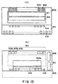
- FIG 13 shows a modification, in which temperature sensors 413 are provided corresponding to groups of different heat generating elements 402 (in the Figure, 413a, 413b, 413c or the like correspond to the respective nozzles). Since the heat generating elements 402 can be selectively driven, the state of ink (ink presence or absence) can be detected for a smaller area by the provision of a plurality of temperature sensors.
- the temperature change upon the liquid ejection can be detected for respective nozzles, and therefore, the presence or absence of the ink in the nozzle and/or the bubble generation state can be detected on the basis of the temperature.
- memory disclosed in Figure 15 may be provided, which stores data indicative of normal ejection, which data is used for comparison.
- the data of adjacent nozzles may be compared. For example, if 413b only is abnormal among 413a, 413b, 413c, for example, the nozzle 413b is discriminated as being abnormal.
- the temperature sensors 413a, 413b, 413c ... are not connected with the respective heat generating resistors through the electrical wiring connection, and therefore, there arises no such a problem that wiring is complicated even if they are provided on the second substrate (top plate 403). Even when a plurality of sensors are provided, the cost rising can be avoided by using semiconductor wafer process, according to the present invention. For this reason, the present invention is particularly preferably used with a full-line head.
- the temperature sensors 413a, 413b are provided on the first and second substrates (element substrate 401 and top plate 403) respectively, as is different from the modified example of showing.
- the control may be improper. But, by the measurement of the difference in the temperature rise by the two sensors during heating, the state of the ink such as ink presence/absence can be more correctly detected than when the sensor is provided only on one substrates.
- memory 469 which stores the temperature changes upon actuation of the heat generating resistor when the ink exists and when the ink does not exist, as head information, and which outputs the stored data to a heat generating element contoller 416.
- the memory may store the head information such as liquid ejection amount properties of the heat generating elements 402 which have been determined beforehand (the liquid ejection amount upon predetermined pulse application at a constant temperature), the used ink or the like.
- Figure 16 is a schematic exploded perspective view of a liquid ejection head cartridge including the liquid ejecting head described in the foregoing, and the liquid ejection head cartridge is generally constituted by a liquid ejecting head 200 and a liquid container 140.
- the liquid ejecting head 200 comprises an element substrate 15L, a top plate 153 provided with an ejection outlet, a confining spring 128, a liquid supply member 130, a aluminum base plate (supporting member)120.
- the element substrate 151 is provided with an array of heat generating resistors for applying heat to the liquid as described hereinbefore.
- the confining spring 128 urges the top plate 153 toward the element substrate 151, by which the element substrate 15L, the top plate 153 and the supporting member 120 are unified. When the top plate and the element substrate are connected by adhesive material with each other, the confining spring is not necessary.
- the supporting member 120 supports the element substrate 151 or the like, and the supporting member 120 is provided with print wiring substrate 123 for supplying electric signals to the element substrate 151 and contact pads 124 for connection with the main assembly of the apparatus for communication therebetween.
- the liquid container 140 contains liquid to be supplied to the liquid ejecting head 200.
- a positioning portion 144 for positioning a connecting member for connection between the liquid container 140 and the liquid ejecting head 200, and a fixed shaft 145 for fixing the connecting member.
- the liquid is supplied through a supply passage of the connecting member from the liquid supply paths 142, 143 of the liquid container 140 to the liquid supply paths 131, 132 of the liquid supply member 130, and is supplied to the common liquid chamber through the liquid supply passages 133, 129, 153c.
- the liquid is supplied from the liquid container 140 to the liquid supply member 130 through two paths, but only one path may be provided.
- the liquid container 140 may be refilled with the liquid after the liquid therein is used up.
- the liquid container 140 is preferably provided with a liquid injection port.
- the liquid ejecting head 200 and the liquid container 140 may be integral or separable.
- FIG 17 shows a general arrangement of a liquid ejecting apparatus loaded with the liquid ejecting head described hereinbefore.
- the liquid ejecting apparatus has a carriage HC which is loaded with a head cartridge including a liquid container 140 for accommodating ink and a liquid ejecting head 200 which are detachable relative to each other, and the carriage reciprocates in a lateral direction (arrows an and b) of the recording material 170 for feeding the recording paper fed by the recording material feeding means.
- the liquid container and the liquid ejecting head are detachable from each other.
- liquid ejecting apparatus of this embodiment further includes a recording material feeding means, a motor 161 as a driving source for driving the carriage HC, gears 162, 163 for transmitting power to the carriage HC from the driving source, and a carriage shaft 164.
- a recording material feeding means a motor 161 as a driving source for driving the carriage HC
- gears 162, 163 for transmitting power to the carriage HC from the driving source
- a carriage shaft 164 With this recording device, the liquid is ejected to various recording materials, so that proper image is formed thereon.
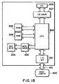
- Figure 18 is a block diagram of the entire apparatus for operating the ink ejection recording apparatus using the liquid ejecting head of the present invention.
- the recording device receives the printing information as the control signal, from the host computer 300.
- the printing information is temporarily stored in the I/O interface 301, and simultaneously it is converted to data which can be processed in the recording device, and then inputted to a CPU302 functioning also as head driving signal supply means.
- the CPU302 processes the data inputted to the CPU302, using peripheral unit such as RAM304, and covert it to printing data(image data).
- the CPU302 produces driving data for driving a driving motor 306 for moving the head 200 and the recording sheet in synchronism with image data to record the image data on a proper portion of the recording sheet.
- the image data and motor driving data are transmitted to the head 200 and the driving motor 306 through the head driver 307 and the motor driver 305 to form the image by driving at controlled timing.
- the recording material usable with the recording devices described above include various paper, OHP sheet, plastic resin material such as compact disk, ornament plate or the like, textile, metal material such as aluminum or copper, leather material such as cattle hide, pigskin or artificial leather, wood material such as wood, plywood, bamboo, ceramic material, such as tile, three-dimensional assembly such as sponge.
- the recording apparatuses include a printer for printing on various paper, OHP sheet or the like, plastic resin material material, printing apparatus for printing on plastic resin material such as compact disk, a metal recording device for printing on metal, a leather recording device for printing on leather, a wood material printing apparatus for printing on wood material, a ceramic recording device for printing on ceramic material, a recording device for printing on a three dimensional material such as sponge, and textile printing apparatus for printing on textile, or the like.
- the ejection liquid usable with the liquid ejecting apparatus is easily selected by one skilled in the art on the basis of the recording material and the recording conditions.
- FIG 19 is a schematic view illustrating an ink jet recording system using the liquid ejecting head of the present invention.
- the liquid ejecting head of this embodiment is a full line type head having ejection outlets arranged with 360dpi over a length corresponding to a recordabie width of the recording material.
- Four of such heads 201a-201d for yellow (Y), magenta (M), cyan (C) and black (Bk) are fixedly supported in parallel with each other in X direction with predetermined gaps between adjacent ones.
- Signals are fed from head drivers 307 constituting the driving signal supply means to the heads 201a-201d, and the heads 201a-201d are driven in response to the signals.
- Four color inks (Y, M, C, Bk) are supplied as the ejection liquid from the ink container 204a-204d to the heads 201a-201d.
- head caps 203a-203d having ink absorbing member such as sponge therein, and during non-recording, they cover the ejection outlets of the heads 201a-201d to maintain the heads 201a-201d.
- Designated by reference numeral 206 is a conveyer belt constituting feeding means for feeding the recording material as described above.
- the conveyer belt 206 is extended along a predetermined path around various rollers, and is driven by a driving roller connected to a motor driver 305.
- pre-processing device 251 and post processing device 252 for carrying out various processings on the recording material before and after the recording operation, upstream and downstream of the recording material feeding path, respectively.
- the post-process and the recording carries out different processing or treatment depending on the material of the recording object or ink material.
- the pre-processing may be application of ultraviolet radiation and ozone to activate the surface, thus improving the deposition property of the ink.
- the pre-process may use an ionizer apparatus to remove the static electricity of the recording material and to remove the dust.
- alkaline substance, water-soluble substance, composite polymeric, water-soluble metallic salt, urea or thiourea may be applied from the standpoint of spread prevention, improvement in the fixing or the like.
- the pre-process is not limited to this, and may be the one for providing proper temperature of the recording material.
- the post- process may be heat treatment, ultraviolet radiation projection or the like, for the recording material having received the ink to promote the fixing of the ink, or it may be the process for removing the processing material remaining as a result of pre-process and non-reaction.
- the head 201a-201d has been described as a full-line head, but this is not limiting, and a small head may be moved in the lateral direction of the recording material.
- the plurality of elements and/or the electric circuits for controlling the driving condition of the energy conversion elements are distributed to the first substrate and the second substrate depending on the their functions, so that liquid ejecting head can be downsized. Additionally, since the function is not concentrated on one substrate, the yield of the substrate is improved, and as a result, the manufacturing cost of the head can be lowered.
- connection electrode By an external contact is provided on one of the first substrate and the second substrate, and opposing surfaces of the first substrate and the second substrate are provided with connection electrode, so that electrical connection between the electric circuits or the elements can be established simultaneously with the coupling or fastening of the first substrate and the second substrate, while the connection with the outside can be effected in the similar manner as conventional manner.
- the element and the electric circuit can be produced using the semiconductor wafer processing technique, and the positional deviation due to the difference in the thermal-expansion between the first substrate and the second substrate can be prevented.
- At least the second substrate may be provided with a temperature sensor, a limitation circuit for limiting or stopping driving of the heat generating resistor in accordance with an output of the temperature sensor, so that difference of the temperature propagation depending on the presence or absence of the ink in the head, and the driving of the heat generating resistor can be limited or stopped on the basis of result thereof.
- the third object 5 can be accomplished.
- each of said liquid flow paths may be provided with a movable member disposed faced to the energy conversion element and having a free end at a downstream side with respect to liquid flow toward then ejection outlet.
Abstract
Description
- The present invention relates to a liquid ejecting head for ejecting a desired liquid using generation of a bubble created by application of thermal energy to the liquid, a head cartridge and a liquid ejecting apparatus which use the liquid ejecting head.
- The present invention is applicable to various apparatus such as a printer, a copying machine, a facsimile machine having a communication system, a word processor having a printer portion, or a printing apparatus, for industrial use, combined with various processing devices, which effect recording on recording materials such as paper, thread, fiber, textile, leather, metal, plastic resin material, glass, wood, ceramic material or the like.
- Here, "recording" means recording of image having any sense such as letters, figures or the like, and recording of patterns not having particular sense.
- An ink jet recording method, or so-called bubble jet recording method is known wherein state change resulting in abrupt volume change is caused in the ink (generation of a bubble) by application of energy such as heat to the ink, and by the force provided by the state change, the ink is ejected from an ejection outlet, and is deposited on the recording material. A recording device using the bubble jet recording method generally comprises an ejection outlet for ejecting ink, an ink flow path in fluid communication with the ejection outlet, and an electrothermal transducer, as energy generating means, for ejecting the ink in the ink flow path, as disclosed in U. S. Patent No. 4, 723, 129, for example.
- Such a recording method is capable of printing high quality image at high speed and with low noise; the printing or recording head using the recording method, the ejection outlets for ejecting the ink can be arranged at high density, and therefore, high resolution image and particularly color image can be easily printed with small size machine. For this reason, the bubble jet recording method is recently used widely for printers, copying machines, facsimile machine machines or other office equipment, and even for industrial systems such as textile printing apparatus or the like.
- The electrothermal transducer for generating energy for ejecting the ink can be manufactured through a semiconductor manufacturing process. Therefore, a conventional head using the bubble jet technique, comprises an element substrate (silicon substrate), electrothermal transducer formed thereon, and a groove for forming an ink flow path is formed thereon, and a top plate of resin material such as polysulfone or the like or glass or the like is combined thereon.
- Utilizing the fact that element substrate is a silicon substrate, in addition to the electrothermal transducers, a driver for driving the electrothermal transducers, and a temperature sensor used to control the electrothermal transducers in accordance with the temperature of the head and a drive control portion or the like may be formed on the element substrate. Figure 20, shows an example of such a structure of the element substrate, In Figure 20, the
element substrate 1001 is provided withheater array 1002 having a plurality of parallel electrothermal transducers for applying thermal energy for ink ejection, adriver circuit 1003 for driving the electrothermal transducers, imagedata transfer circuit 1004 for parallel transfer of the image data inputted serially from outside to adriver circuit 1003, and aninput contact 1007 for inputting the image data and various signals or the like from outside. Theelement substrate 1001 is provided with a temperature sensor for sensing a temperature of theelement substrate 1001, a resistance sensor for sensing a resistance value of the electrothermal transducers, or anothersensor 1006, and adrive control portion 1005 for driving thesensor 1006 and for controlling a width of the driving pulse for the electrothermal transducers in accordance with an output from thesensor 1006. A head having the driver, the temperature sensor and the drive control portion on the element substrate has been put in practical use, with high reliability of the recording head and small size. - However, recently, a higher image quality is demanded.
- As a result of inventors investigations, the following points to be improved have been found, if the density of the ejection outlets and therefore the electrothermal transducers is increased in an attempt to improve the image quality, and the electrothermal transducers are further precisely controlled.
- If the circuits for controlling the electrothermal transducers are all formed on the element substrate, the size of the element substrate is bulky with the result of bulky head.
- When the ejection outlets are arranged at a high density such as 600dpi or 1200dpi or higher, precise alignment is required between the electrothermal transducers and ink flow paths, and the difference in the thermal-expansion between the element substrate and the top plate resulting from the heat during the driving of the electrothermal transducers, is not negligible.
- In the case of a head capable of ejecting fine droplets (as a result of a high density arrangement of the ejection outlets, for example), if the heater is actuated when the ink is out, there is a liability that influence of the physical damage such as the surface damage of the heater to the ejection property is more significant than a conventional head ejecting larger droplets.
- Accordingly, it is a principal object of the present invention to provide a liquid ejecting head, head cartridge and a recording device using the same which is small despite addition of various functions for controlling ejection of the liquid.
- It is another object of the present invention to provide a liquid ejecting head wherein positional deviation due to the difference in the thermal-expansion between the element substrate and the top plate can be prevented.
- It is a further object of the present invention to provide a liquid ejecting head wherein an ink detecting mechanism is provided to prevent the damage of the heater.
- According to an aspect of the present invention, there is provided a liquid ejection head comprising a plurality of ejection outlets for ejecting liquid; a first substrate and a second substrate for constituting a plurality of liquid flow paths in fluid communication with said ejection outlets, respectively when combined with each other; a plurality of energy conversion elements disposed in said liquid flow paths, respectively to convert electrical energy to ejection energy for the liquid in said liquid flow paths; a plurality of elements or electric circuits having different functions for controlling driving conditions of said energy conversion elements; wherein said elements and electric circuits are provided either on said first substrate and said second substrate, depending on their functions.
- The elements or the electric circuits are not concentrated on one of the substrates, so that liquid ejecting head is downsized.
- The electrical connection with the outside are not effected by each of the function element and the electric circuit, but an outer contact for electrical connection of the element or the electric circuit with the outside is provided on either one of the first substrate and the second substrate, and the outer contact electrically connects the elements or electric circuits with outside on either one of the first substrate or second substrate, and a connection electrode for electrical connection of the elements or electric circuits on such surfaces of the first substrate and second substrate as are opposed to each other, so that they are electrically connected by combining the first substrate and the second substrate Since the connection with the outside is concentrated on one of the substrates, further downsizing can be accomplished.
- The selection may be such that such an element or electric circuit of all of the elements or electric circuits as are electrically connected to said energy conversion elements on individual or group basis, is provided on such one of the substrates as is provided with the energy conversion elements, and the other element or electric circuit is provided on the other substrate. By this, the number of electrical connections between the first substrate and the second substrate decreases so that liability of defective connection can be reduced. Such an element or electric circuit of all of the elements or electric circuits as are electrically connected to the energy conversion elements on individual or group basis, may include drivers for driving said energy conversion elements. With the use of the feature that external connection contacts are provided only on one substrate, further downsizing is accomplished.
- By making the first substrate and the second substrate from silicon material, the element or the electric circuit can be manufactured through a semiconductor wafer processing technique. Because the first substrate and the second substrate are made of the same materials, the deviation therebetween due to thermal-expansion difference can be avoided. Therefore, the second object can be accomplished.
- At least the second substrate may be provided with a temperature sensor, a limitation circuit for limiting or stopping driving of the heat generating resistor in accordance with an output of the temperature sensor, so that difference of the temperature propagation depending on the presence or absence of the ink in the head, and the driving of the heat generating resistor can be limited or stopped on the basis of result thereof. Thus, the third object can be accomplished. By manufacturing the temperature sensor and the limitation circuit using the semiconductor wafer processing technique, highly accurate detection of presence or absence of the ink is possible without cost increase.
- The energy conversion elements generate bubbles in the liquid by application of thermal energy, and each of said liquid flow paths may be provided with a movable member disposed faced to the energy conversion element and having a free end at a downstream side with respect to liquid flow toward then ejection outlet. By doing so, the propagating direction of the pressure resulting from the generation of the bubble and the expanding direction of the bubble per se can be directed toward the downstream side by the movable member, so that ejection property such as the ejection efficiency, the ejection power or the ejection speed is improved.
- In this specification, "" and "" is with respect to the direction of flow of the liquid toward the ejection outlet through a bubble generating region (or movable member) from the supply source of the liquid.
- These and other objects, features and advantages of the present invention will become more apparent upon a consideration of the following description of the preferred embodiments of the present invention taken in conjunction with the accompanying drawings.
-
- Figure 1 is a sectional view of a liquid ejecting head according to an embodiment of the present invention, taken along a liquid flow path.
- Figure 2 illustrates a circuit of the liquid ejecting head of Figure 1, wherein (a) is a top plan view of the element substrate and (b) is a top plan view of the top plate.
- Figure 3 is a top plan view of a liquid ejecting head unit loaded with the Figure 3 of Figure 1.
- Figure 4 shows circuits of an element substrate and a top plate in an example wherein applied energy to the heat generating element is controlled in accordance with a sensor output.
- Figure 5 shows circuits of an element substrate and a top plate in an example wherein a temperature of the element substrate is controlled in accordance with a sensor output.
- Figure 6 is a perspective view and a sectional view of a liquid ejecting head according to another embodiment of the present invention.
- Figure 7 is a perspective view and a sectional view of a liquid ejecting head according to a further embodiment of the present invention.
- Figure 8 is a perspective view and a sectional view of a liquid ejecting head according to a further embodiment of the present invention.
- Figure 9 is a perspective view and a sectional view of a liquid ejecting head according to a further embodiment of the present invention.
- Figure 10 is a perspective view and a sectional view of a further example of a liquid ejecting head according to the present invention.
- Figure 11 shows an element substrate and a top plate in an embodiment wherein presence or absence of the ink is detected on the basis of an output of a temperature sensor.
- Figure 12 shows a modified embodiment of the element substrate and the top plate of Figure 11 wherein circuit structures are modified.
- Figure 13 shows a modified embodiment of the element substrate and the top plate of Figure 11 wherein circuit structures are modified.
- Figure 14 shows a modified embodiment of the element substrate and the top plate of Figure 11 wherein circuit structures are modified.
- Figure 15 shows a modified embodiment of the element substrate and the top plate of Figure 11 wherein circuit structures are modified.
- Figure 16 is an exploded perspective view of a liquid election head cartridge usable with the present invention.
- Figure 17 is a schematic illustration of a liquid ejecting apparatus to which the present invention is applicable.
- Figure 18 is an apparatus block diagram of a liquid ejecting apparatus to which the present invention is applicable.
- Figure 19 shows a liquid ejection system to which the present invention is applicable.
- Figure 20 shows a circuit of an element substrate of a conventional head.
-
- Figure 1 is a sectional view, taken along a line parallel with a liquid flow path, of a liquid ejecting head according to an embodiment of the present invention.
- As shown in Figure 1, the liquid ejecting head comprises an
element substrate 1 on which a plurality of heat generating elements 2 (only one of them is shown in Figure 1) for applying thermal energy for generating bubbles to liquid are disposed in parallel, atop plate 3 connected to theelement substrate 1, an orifice plate 4 connected to the leading edge surface of thetop plate 3, and amovable member 6 placed in a liquid flow path 7 constituted by theelement substrate 1 and thetop plate 3. - The
element substrate 1 comprises a substrate of silicon or the like, a silicon oxide film or silicon nitride film thereon for electric insulation and heat accumulation, and an electric resistance layer (heat generating element 2) and wiring patterned thereon. The electric resistance layer is supplied with a voltage through the wiring to supply the current to the electric resistance layer, so thatheat generating element 2 generates heat. - The
top plate 3 cooperates to constitute liquid flow paths 7 corresponding to theheat generating elements 2, respectively, and acommon liquid chamber 8 for supplying the liquid to the liquid flow paths 7, and it includes integral side walls extending from the top between theheat generating elements 2. Thetop plate 3 is a silicon material, and is manufactured by etching the liquid passage pattern and the common liquid chamber pattern, or by overlying on the silicon substrate silicon nitride material, silicon oxide or the like through known CVD method or the like to constitute the side walls, and then etching the liquid passage portions. - The orifice plate 4 is provided with
ejection outlets 5 which are formed corresponding respective liquid passages and which are in fluid communication with thecommon liquid chamber 8 through the liquid passages. The orifice plate 4 is of silicon material too, and is manufactured by machining a silicon substrate havingejection outlets 5 into a thickness of approx. 10-150µm. In the present invention, the orifice plate 4 is not an inevitable element, and in place of the provision thereof, a wall of a thickness corresponding to the orifice plate 4 may be caused to remain at the end surface of thetop plate 3 when the liquid flow path is formed in thetop plate 3, and theejection outlets 5 may be formed in the remaining portion. - The
movable member 6 separates the liquid flow path 7 to a firstliquid flow path 7a in fluid communication with theejection outlet 5 and asecond release path 7 b having aheat generating element 2, and is disposed opposed to theheat generating element 2. It is in the form of a thin film cantilever of silicon material such as silicon nitride, silicon oxide or the like. - The
movable member 6 has afulcrum 6a at an upstream with respect to a major liquid flow from thecommon liquid chamber 8 to theejection outlet 5 viamovable member 6 upon the liquid ejecting operation and has afree end 6b downstream of thefulcrum 6a, and it is extended as if it covers theheat generating element 2 with a predetermined distance from theheat generating element 2. The space between theheat generating element 2 and themovable member 6 is abubble generating region 10. - With this structure, when the
heat generating element 2 is actuated, the heat is applied to the liquid on theheat generating element 2, by which a bubble is generated by film boiling phenomenon on theheat generating element 2. The pressure resulting from expansion of the bubble is applied mainly to themovable member 6, and therefore, themovable member 6 is widely opened toward theejection outlet 5 as indicated by broken line in Figure 1, generally about thefulcrum 6a. By the displacement of themovable member 6 and/or the state thereof, the pressure resulting from the generation of the bubble is propagated, and the expansion of the bubble per se is directed toward theejection outlet 5, and the liquid is ejected from theejection outlet 5. - Thus, by the provision, above the
bubble generating region 10, of themovable member 6 having afulcrum 6a upstream with respect to the flow of the liquid in the liquid flow path 7 (commonliquid chamber 8 side) and thefree end 6b at the downstream side (ejection outlet 5 side), the pressure propagation of the bubble is directed toward the downstream side, so that pressure of the bubble is directly and therefore effectively used for the liquid ejection. And, the direction of the bubble expansion per se is similarly directed to the downstream side, and therefore, the bubble expands more in the downstream side than in the upstream side. Thus, the expansion direction per se of the bubble is controlled by the movable member to control the pressure propagating direction of the bubble, so that fundamental ejection properties such as the ejection efficiency, ejection power the ejection speed and/or the like. - On the other hand, in the bubble collapse process, the bubble collapses rapidly synergetically with the elastic force of the
movable member 6, and themovable member 6 finally restores to the initial position indicated by the solid line in Figure 1. At this time, the liquid flows into the liquid flow path 7 from the upstream, more particularly, from thecommon liquid chamber 8 to compensate for the contraction volume of the bubble in thebubble generating region 10 or to compensate for the amount of the ejected liquid (refilling of the liquid). The refilling is efficient because of the restoring function of themovable member 6. - The liquid ejecting head of this embodiment comprises circuits and elements for driving the
heat generating element 2 or controlling the driving. The circuits and the element are not concentrated on one of theelement substrate 1 and thetop plate 3, but are allotted to them on the basis of the functions. Since theelement substrate 1 and thetop plate 3 are of silicon material, the circuits and the elements can be easily and finely formed through semiconductor wafer processing technique. - The structure of the circuits on the
element substrate 1 and thetop plate 3 will be described. - Figure 2 illustrates a circuit structure of the liquid ejecting head shown in Figure 1, wherein (a) is a top plan view of the element substrate, (b) is a top plan view of the top plate. In Figure 2, (a) and (b) show the opposing sides.
- As shown in Figure 2, (a), the
element substrate 1 is provided with a plurality ofheat generating elements 2 arranged in parallel with each other, drivers 11 for driving theheat generating elements 2 in accordance with the image data, an imagedata transfer portion 12 for supplying the inputted image data to the driver 11 and asensor 13 for measuring a parameter necessary for controlling the driving condition for theheat generating element 2. - The image
data transfer portion 12 comprises a shift register for outputting the image data supplied in series, to the drivers 11, in parallel, and a latching circuit for storing temporarily the data outputted from the shift register. The imagedata transfer portion 12 may output the image data to the respectiveheat generating elements 2 or may output the image data for respective blocks ofheat generating elements 2 into which theheat generating element 2 are grouped. By providing a plurality of shift registers for one head and by transmitting the data from the recording device through a plurality of shift registers, the printing speed can be increased easily. - The
sensor 13 may be a temperature sensor for sensing the temperature adjacent to theheat generating element 2, or a resistance sensor or the like for monitoring the resistance value of theheat generating element 2. - The ejection amount of the ejected droplet is mainly dependent on the generated bubble volume of the liquid. The generated bubble volume of the liquid is dependent on the temperature of the
heat generating element 2 and the portion therearound. Therefore, the temperature of theheat generating element 2 and the temperature therearound are measure, and a pulse of such a small energy as is insufficient for liquid ejection(preheating pulse) is applied before application of a beating pulse for liquid ejection, and the pulse width or the output timing of the preheating pulse is changed in accordance with the output of the sensor, so that temperature of theheat generating element 2 and the temperature therearound is adjusted to assure that constant droplets are ejected, thus maintaining the image quality. - The energy necessary for the bubble generation is represented by a required energy per unit area of the
heat generating element 2 multiplied by an area of theheat generating element 2, if the heat radiation condition is constant. The voltage between the opposite ends of theheat generating element 2, the current flowing through theheat generating element 2 and the pulse width thereof, are selected to provide the necessary energy. As regards the voltages applied to theheat generating elements 2, can be maintained substantially constant by supply it from the voltage source of the main assembly of the liquid ejecting apparatus. On the other hand, as regards the currents through theheat generating elements 2, the resistance values of theheat generating elements 2 may be different depending on the lots of theelement substrates 1 andindividual element substrates 1, because of the variation or the like of the film thicknesses of theheat generating element 2 in the manufacturing process. Therefore, if the pulse width applied to theheat generating element 2 is constant, and the resistance value of theheat generating element 2 is larger than the design value, the current is lower, with the result of insufficiency of the supplied energy, so that bubble generation cannot be proper. On the contrary, when the resistance value of theheat generating element 2 is smaller, the current is larger even when the voltage is the same. In this case, theheat generating element 2 is supplied with excessive energy, with the possible result of damage to, or service life reduction of, theheat generating element 2. Therefore, there is a method wherein the resistance values of theheat generating elements 2 are always monitored by the resistance sensor, and the power source voltage or the heating pulse width is changed in accordance with the resistance value so thatheat generating elements 2 are supplied with substantially constant energy. - On the other hand, as shown in Figure 2, (b), the
top plate 3 is provided withgrooves sensor driver 17 for driving thesensor 13 provided on theelement substrate 1, and a heatgenerating element controller 16 for controlling the driving condition for theheat generating element 2 in accordance with the output of the sensor driven by thesensor driver 17. Thetop plate 3 is provided with asupply port 3c in fluid communication with the common liquid chamber to permit supply of the liquid into the common liquid chamber for the outside. - The stations of the
element substrate 1 and thetop plate 3 which are opposed to each other when they are connected, are provided withcontact pads element substrate 1 and the circuits and the like provided on thetop plate 3. Theelement substrate 1 is provided with an outer orexternal contact pad 15 functioning as input contacts for receiving external electric signals. The size of theelement substrate 1 is larger than that of thetop plate 3, and theexternal contact pad 15 is extended out of thetop plate 3 wen theelement substrate 1 and thetop plate 3 are connected. - The description will be made as to examples of formation processes of the circuits or the like on the
element substrate 1 and thetop plate 3. - As regards the
element substrate 1, the circuits which constitutes the driver 1L, the imagedata transfer portion 12 and thesensor 13 are first formed on the silicon substrate through a semiconductor wafer processing technique. Subsequently, as described, hereinbefore, theheat generating element 2 is formed, and finally, thecontact pad 14 and theexternal contact pad 15 are formed. - As regards the
top plate 3, the circuits constituting the heatgenerating element controller 16 and thesensor driver 17 are formed on the silicon substrate by a semiconductor wafer processing technique. Then, as described hereinbefore, thegrooves supply port 3c are formed by film,formation and etching, and finally, theconnection contact pad 18 are provided. - The thus constituted
element substrate 1 and thetop plate 3 are aligned and coupled, by which theheat generating elements 2 are aligned with the liquid flow paths, and the circuits and the like of theelement substrate 1 and thetop plate 3 are electrically connected with each other through thepads pads contact pads element substrate 1 and thetop plate 3, the electrical connection is established simultaneously with the coupling between theelement substrate 1 and thetop plate 3. - As shown in Figure 1, the liquid ejecting head of this embodiment comprises the
movable member 6, and therefore, themovable member 6 is placed on theelement substrate 1 before theelement substrate 1 and the connection is joined with each other. After the coupling between theelement substrate 1 and thetop plate 3, the orifice plate 4 is connected to the front side of the liquid flow path 7, so that liquid ejecting head 21 (Figure 3) is provided. - When the
liquid ejecting head 21 thus manufactured is installed in the liquid ejecting apparatus or is mounted to the head cartridge which will be described hereinafter, theliquid ejecting head 21 is fixed on abase substrate 22 having aprint wiring substrate 23 as shown in Figure 3, so as to constitute a liquidejecting head unit 20. As shown in Figure 3, theprint wiring substrate 23 is provided with a plurality ofwiring patterns 24 for electrical connection with the head controller of the liquid ejecting apparatus, and thewiring patterns 24 are electrically connected with theouter contact pads 15 through thebonding wire 25. Theouter contact pads 15 are provided only on theelement substrate 1, and therefore, the electrical connection between theliquid ejecting head 21 and the outside can be established in the same manner as in a conventional liquid ejecting head. In this example, theexternal contact pads 15 are provided on theelement substrate 1, but they may be provided on only on thetop plate 3 not on theelement substrate 1. As described hereinbefore, the various circuits for driving and controlling theheat generating element 2, are distributed to theelement substrate 1 and to thetop plate 3 in consideration of the electrical connection between the first and second substrates, so that circuits are not concentrated on one substrate, and therefore, the liquid ejecting head can be downsized. By the provision of the electric connecting portions for the electrical connection at portions where the first and the second substrates are connected for constitution of the head, the number of the electrical connecting portions of the head for the external connection is reduced, so that reliability is improved, and the number of parts is reduced, thus accomplishing further downsizing the head. - By not concentrating the circuits on one of the
element substrate 1 and thetop plate 3, the yield ofelement substrate 1 can be improved, and as a result, the manufacturing cost of the liquid ejecting head can be reduced. Sinceelement substrate 1 and thetop plate 3 are both made of the silicon base material, thermal expansion coefficients of theelement substrate 1 and thetop plate 3 are the same. As a result, even if the thermal-expansion occurs in theelement substrate 1 and thetop plate 3, they keep the alignment therebetween, and therefore, the alignment between the respectiveheat generating elements 2 and the liquid flow paths 7. - In this embodiment, the circuits are divided into an element substrate groups and a top plate group depending on the functions thereof. The criteria of the grouping will be described.
- The circuit or circuits corresponding to the individual
heat generating elements 2 or to blocks of theheat generating elements 2 through electric wiring, are formation d on theelement substrate 1. In the example shown in Figure 2, the drivers 11 and the imagedata transfer portion 12 are those circuits. Since theheat generating elements 2 receive the driving signals in parallel, the wiring is required for the number of the signals. If such a circuit is formed on thetop plate 3, the number of electric connections between theelement substrate 1 and thetop plate 3 is large with the result of higher liability of the connection defect, but the liability can be reduced by providing those circuits on theelement substrate 1. - The analog circuit or circuits such as a control circuit, is provided on the
top plate 3 not having theheat generating element 2, since it is easily influenced by heat. In the example shown in Figure 2, the heatgenerating element controller 16 is this circuit. - The
sensor 13, may be provided either one of theelement substrate 1 and thetop plate 3, as desired. For example, if it is a resistance sensor, it is desirable to provide it on theelement substrate 1 to assure the measurement accuracy. If it is a temperature sensor, it is preferable to provide it on the element substrate 1 (first substrate) when it is for detecting the temperature rise due to abnormality of the heater driving circuit; and when it is for discriminating the state of the ink using the temperature rise of the ink, it is preferable to provide it on the top plate 3 (second substrate) or on each of the element substrate and the top plate. - Other circuits such as a circuit not corresponding to the
heat generating elements 2 or blocks of theheat generating elements 2 through electric wiring, a circuits not required to be provided on theelement substrate 1, a sensor or the like of which the measurement accuracy is not influenced, may be provided on either one of theelement substrate 1 and thetop plate 3 so as to avoid concentration on one of them. In the example shown in Figure 2, thesensor driver 17 is this type of circuit. - By distributing the circuits and the sensors on the basis of the criteria described above, they can be distributed with good balance without minimizing the number of electrical connections between the
element substrate 1 and thetop plate 3. - More specific examples of the circuits will be described.
- Figure 4 shows an example of the circuit structures on the element substrate and the top plate in which the applied energy to the heat generating element is controlled in accordance with the sensor output.
- As shown in Figure 4, (a), on the element substrate 31 are formed
heat generating elements 32 arranged in a line,power transistors 41 functioning as drivers, ANDcircuits 39 for controlling the driving of thepower transistors 41, a drive timingcontrol logic circuit 38 for controlling the drive timing of thepower transistors 41, an imagedata transfer circuit 42 comprising the shift registers and latching circuits, and asensor 43 for detecting the resistance value of theheat generating element 32. - The drive timing
control logic circuit 38 functions for divided drive of the heat generating elements 32 (the electric power is not supplied simultaneously to all of the heat generating element 32) to reduce the capacity of the voltage source of the apparatus, and an enabling signal for driving the drive timingcontrol logic circuit 38 is supplied through enablingsignal input contacts 45k-45n which are external or outer contact pads. - In addition to the enabling
signal input contacts 45k-45n, the outer contact pads provided on the element substrate 31 include an input contact 45a for supplying electric energy to theheat generating elements 32, agrounding contact 45b for thepower transistors 41,input contacts 45c-45e for the signal necessary for controlling the energy driving theheat generating elements 32, a drivingvoltage source contact 45f for the logic circuit, a grounding contact 45g, aninput contact 45i for the serial data to be supplied to the shift register of the imagedata transfer circuit 42, aninput contact 45h for a serial clock signal in synchronization therewith, and aninput contact 45j for a latch Clock signal to be supplied to the latching circuit. - On the other hand, as shown in Figure 4, (b), on the
top plate 33 are formed asensor driving circuit 47 for driving thesensor 43, a drivingsignal control circuit 46 for monitoring the output of thesensor 43 and for controlling the applied energy to theheat generating elements 32 in accordance with outputs of thesensor 43,memory 49 for storing, as head information, the resistance value data sensed by thesensor 43 or a coded rank values of the resistance value data, and the liquid ejection amount properties of theheat generating elements 32 which are measured beforehand (the liquid ejection amounts with a predetermined pulse application under a predetermined temperature) and for outputting the information to the drivingsignal control circuit 46. - As for the contact pads for the electric connection, the element substrate 31 and the
top plate 32 are provided withcontacts sensor 43 and thesensor driving circuit 47,contacts 44b-44d, 48b-48d for connection between theinput contacts 45c-45e and the drivingsignal control circuit 46, and acontact 48a for inputting the output of the drivingsignal control circuit 46 into one of the input contacts of the ANDcircuit 39, as shown in the Figure. - With such a structure, the resistance value of the
heat generating element 32 is detected by thesensor 43, and the results thereof are stored in thememory 43. The drivingsignal control circuit 46 determines rising and falling data for the driving pulse for theheat generating element 32 in accordance with the resistance value data and the liquid ejection amount property stored in thememory 43, and supplies the determined data to the ANDcircuit 39 through thecontacts 48a, 44a. On the other hand, the image data inputted in series are stored in a shift register of the imagedata transfer circuit 42, and are latched in the latching circuit by a latching signal, and is supplied to the ANDcircuit 39 through the drivetiming control circuit 38. By doing so, the pulse width of the heating pulse is determined in accordance with the rising and falling data, and theheat generating element 32 is actuated with the pulse width. As a result, theheat generating element 32 is supplied with a substantially constant energy. - In the foregoing example, the
sensor 43 is a resistance sensor. It may be a temperature sensor for detecting a degree of heat accumulation of theheat generating element 32 or for detecting a temperature of the element substrate 31, and the preheating pulse width may be controlled in accordance with the output of the temperature sensor. - In this case, the driving
signal control circuit 46 determines the preheat width of theheat generating element 32 in accordance with the liquid ejection amount property determined beforehand and the temperature data detected by thesensor 43, after the voltage source of the liquid ejecting apparatus is actuated. Thememory 49 stores selection data for selecting preheat widths corresponding to the respectiveheat generating elements 32, and when the preheat is actually effected, the preheating signal is selected in accordance with the selection data stored in thememory 49; and then, theheat generating elements 32 are preheated in accordance therewith. In such a manner, the preheating pulse is so selected and applied that ejection amounts of the respective ejection outlets are uniform irrespective of the temperature state. The selection data which determine the preheat width may be once stored at the time of the start of the liquid ejecting apparatus. - In the example of Figure. 4, one
sensor 43, is used, but two sensors (resistance sensor and temperature sensor) may be provided, and both of the heating pulse and the preheating pulse are controlled in accordance with the respective outputs, by which the image quality can be further improved. - The head information stored in the
memory 49 may include a nature of the liquid to be ejected (when the liquid is ink, the nature may be the color of the ink or the like) in addition to the resistance value data of the heat generating elements. This is because, the properties of the liquids may be different, and therefore, the ejection properties are different. The head information may be stored in thememory 49 after the liquid ejecting head is assembled as non-volatile memory, or the information may be supplied from the apparatus after installation of the liquid ejecting apparatus loaded with the liquid ejecting head. - In the example shown in Figure 4, the
sensor 43 is provided on the element substrate 31, but when thesensor 43 is a temperature sensor, it may be provided on thetop plate 33. As regards thememory 49, it may be provided on the element substrate 31 not on thetop plate 33 if the element substrate 31 has enough space. - As described in the foregoing, even if the drive or actuation of the
heat generating elements 32 are controlled so as to provide good image qualities, the liquid may not be ejected despite the liquid is in the common liquid chamber, if bubbles exist in the common liquid chamber and are introduced to the liquid flow paths with the refilling of the liquid. - As a countermeasurement, a sensor may be provided to detect the presence or absence of the liquid in each of the liquid flow path (particularly, adjacent the heat generating element 32) (detail thereof will be described hereinafter), and when the absence of the liquid may be detected by the sensor, the event may be supplied to the outside. A process circuit for this purpose may be provided on the
top plate 33. In this case, the liquid in the liquid ejecting head is forcedly sucked out through the ejection outlets by the liquid ejecting apparatus in response to the output of the process circuit, by which the bubble in the liquid flow path can be removed. The senor for detecting the presence or absence of the liquid may effect the detection using the change of the resistance value through the liquid or using an abnormal temperature rise of the heat generating element in the absence of the liquid. - Figure 5 shows an example of circuit structures on the element substrate and the top plate for controlling the temperature of the element substrate in accordance with a sensor output.
- In this example, as shown in Figure 5, (a), on the
element substrate 51 is formed atemperature keeping heater 55 for heating theelement substrate 51 per se to control the temperature of theelement substrate 51 in addition to theheat generating elements 52 for the liquid ejection, and apower transistor 56 as a driver for thetemperature keeping heater 55, as compared with the element substrate 31 shown in Figure 4, (a). Thesensor 63 is a temperature sensor for measuring the temperature of theelement substrate 51. On the other hand, as shown in Figure 5, (b), on thetop plate 53 is formed asensor driving circuit 67 for driving thesensor 63 and a temperature keepingheater control circuit 66 for monitoring the output of thesensor 63 and for controlling the driving of thetemperature keeping heater 55 in accordance with the output of thesensor 63, in addition to thememory 69 storing the liquid ejection amount properties. The temperature keepingheater control circuit 66 includes a comparator which compares an output of thesensor 63 with a threshold predetermined on the basis of the temperature required for theelement substrate 51, and when the output of thesensor 63 is higher than the threshold, a temperature keeping heater control signal for driving thetemperature keeping heater 55 is outputted. The temperature required for theelement substrate 51 is such a temperature with which the viscosity of the liquid in the liquid ejecting head is within a stable ejection range. -
Contacts 64a, 68a for inputting a temperature keeping heater control signal outputted from the temperature keepingheater control circuit 66 to thepower transistor 56 for the temperature keeping heater formed on theelement substrate 51, are provided on theelement substrate 51 and thetop plate 53 as contact pads. The structures in the other respect is the same as those shown in Figure 4, and therefore, the detailed explanation is omitted for simplicity. - With this structure, the
temperature keeping heater 55 is actuated by the temperature keepingheater control circuit 66 in accordance with the output of thesensor 63, so that temperature of theelement substrate 51 is maintained at a predetermined temperature. As a result, the viscosity of the liquid in the liquid ejecting head is maintained within a stable ejection range, thus assuring proper ejection. - Individual sensors usable as the
sensor 63 involves variation in the voltage outputs. Therefore, a further accurate temperature control is desired, a correction value for compensating the variation may be stored in thememory 69 as head information, and the threshold set in the temperature keepingheater control circuit 66 may be adjusted in accordance with the correction value stored in thememory 69. In the embodiment of Figure 1, the grooves constituting the liquid flow paths 7 are formed in thetop plate 3, and themovable members 6 are manufactured in a process separate from that for theelement substrate 1, and the member provided with the ejection outlets 5 ((orifice plate 4) is made of a member separate from theelement substrate 1 and from thetop plate 3. However, the present invention is not limited to this case. - Figures 6-10 show another example of the element substrate and the top plate. The example of Figures 4 and 5 is applicable to the liquid ejecting heads according to the embodiments of Figures 6-10, which will be described. In the following description, the structure of the liquid ejecting head is taken, and the structure of the electric circuits are omitted for simplicity.
- In the example of Figure 6, the
movable members 76 are built in theelement substrate 71, and thetop plate 3 is provided with theejection outlets 75. Themovable member 76 is directly formed on theelement substrate 71 through a film formation process after theheat generating element 72 is formed on theelement substrate 71. At this time, the upper part of theheat generating element 72 is treated for weakening the contact, by which the movable member can be formed into a cantilever. As regards thetop plate 73, when the grooves constituting theliquid flow paths 77 and thecommon liquid chamber 78 are formed in thetop plate 73, a wall having a thickness of the orifice plate is caused to remain at the end surface of thetop plate 73, and theejection outlets 75 are formed through the wall by ion beam machining, electron beam process or the like. - In the example shown in Figure 7, the grooves constituting the
liquid flow paths 87 andcommon liquid chamber 88 are formed in theelement substrate 81, and thetop plate 83 has a supply port 83c only as opening. After theheat generating elements 82 are formed on theelement substrate 81, themovable members 86 are formed on theelement substrate 81. Thereafter, the material comprising as a main material silicon material such as silicon nitride, silicon oxide or the like is formed into a film on theelement substrate 81, and then, the portions of the walls corresponding to the orifice plate and theside walls 89 of the flow paths, are patterned. Subsequently, similarly to Figure 6,ejection outlets 85 are formed, and finally, thetop plate 83 is connected. In this example, theheat generating elements 82, theliquid flow paths 87, themovable members 86 are all formed using semiconductor wafer processing technique, and theejection outlets 85 are formed by patterning, so that liquid flow paths are provided with high accuracy. Accuracy of the fastening of thetop plate 83 is dependent on the machine assembling accuracy, but what is done is to connect the supply ports 83c with theliquid flow paths 87, and the ejection performance is determined by the liquid flow passage configurations, and therefore, a less expensive assembling machine is enough for the desired accuracy. - In the example shown in Figure 8, the liquid ejecting head is an ordinary one not having the movable member, and the structure thereof is the same as that of Figure 1 in the other respects. More particularly, grooves constituting the
liquid flow paths 97 and thecommon liquid chamber 88 are formed in theelement substrate 91 having theheat generating elements 92 formed thereon, and thetop plate 93 having the supply port 93c formed therein is fastened thereto, and then, anorifice plate 94 having theejection outlets 95 formed therein is connected or fastened to the front end of theunited element substrate 91 andtop plate 93. - In the example of Figure 9, there is not provided a movable member, and the
ejection outlets 105 are formed in thetop plate 103. In theelement substrate 101, only theheat generating elements 102 are formed, and the other structures are the same as that shown in Figure 6, and therefore, the detailed description thereof is omitted. - In the example shown in Figure 10, there is not provided a movable member, and the
ejection outlets 115 are formed in the element substrate 111. The structure of the element substrate 111 is the same as that shown in Figure 7 except that movable member is not provided, and the structure of thetop plate 113 is the same as that shown in Figure 7, so that detailed description thereof is omitted. - Referring to Figures 11-15, the description will be made as to a head driving operation in accordance with a result of detection and detection of presence/absence of the ink, using the temperature sensor.
- Figures 11-15 show a further structures of circuits the element substrate and the top plate of the liquid ejection recording head according to embodiments of the present invention, in each of which (a) is a top plan view of the element substrate, and (b) is a top plan view of the top plate. These Figures show the opposing surfaces similarly to Figure 2 in (a) and (b), and the broken lines on (b) indicates the position of the liquid chamber and the Figure when the they are united.
- The heads shown in Figures 11-15 are not provided with the movable member shown in Figure 10, and the ejection outlets are formed in the element substrate, but as regards the structures of the element substrate and the top plate, they are applicable to any examples having been shown. In the following description, the examples can be combined within the sprit of the present invention, unless particular mentioning to the contrary is made. In the following examples, the like reference numerals or characters are assigned to the elements having the corresponding functions.
- In Figure 11, (a), the
element substrate 401 are provided with a plurality ofheat generating elements 402 arranged in parallel corresponding to the flow paths described above, a sub-heater 455 in the common liquid chamber,drivers 411 for actuating theheat generating elements 402, an imagedata transfer portion 412 for outputting the image data to thedriver 411, flow passage walls 401a for constituting the nozzles and aliquid chamber frame 401b. - On the other hand, in Figure 11, (b), the
top plate 403 is provided with atemperature sensor 413 for measuring a temperature in the common liquid chamber, asensor driver 417 for actuating thetemperature sensor 413, alimitation circuit 459 for limiting or stopping driving of the heat generating resistors, a heatgenerating element controller 416 for controlling a driving condition of theheat generating elements 402 on the basis of the signals from thesensor driver 417 and thelimitation circuit 459, and asupply port 403a in fluid communication with the common liquid chamber to supply the liquid into the common liquid chamber from outside. - Additionally, the opposing surfaces of the
element substrate 401 and thetop plate 403 are provided withconnection contact pads element substrate 401 and the circuits or the like formed thetop plate 403. The element substrate 40 1 is provided with an outer or external contact pad 4 15 functioning as input contacts for receiving external electric signals The size of the element substrate 40 1 is larger than that of the top plate 40 3, and the external contact pad 4 15 is extended out of the top plate 40 3 wen theelement substrate 1 and the top plate 40 3 are connected. They are formed in the same manner as with Figure 2 embodiment. The thus constituted element substrate 40 1 and thetop plate 403 3 are aligned and coupled, by which the heat generatingelement 40s 2 are aligned with the liquid flow paths, and the circuits and the like of theelement substrate 1 and thetop plate 3 are electrically connected with each other through thecontact pad - The ink is filled in a gap of several tens microns between the first substrate (element substrate 401) and the second substrate (top plate 403). When the heating is carried out by the sub-heater 455, the heat transfer to the second substrate is different depending on the presence or absence of the ink. The difference of the heat transfer is detected by a
temperature sensor 413 constituted by a diode sensor or the like having PN junction to discriminate the presence or absence of the ink in the liquid chamber. Therefore, when an abnormality temperature as compared with that when the ink is present, is detected on the basis of the detection result by thetemperature sensor 413, the actuation of theheater 402 is limited or stopped by thelimitation circuit 459, or a signal indicative of the abnormality is supplied to the main assembly, so that physical damage of the head can be prevented, and the stabilized ejection performance can be maintained. - According to the present invention, the temperature sensor and the limitation circuit can be manufactured through the semiconductor wafer processing technique, and therefore, the elements can be placed at the optimum locations, and the damage, preventing function for the head can be added without cost rise.
- Figure 12 shows a modification of Figure 11 embodiment, and in this modified example, the use is made with an ejection heater i.e.
heat generating resistor 402 rather than the sub-heater, as is 5 different from Figure 11 embodiment. In the modified example of Figure 12, thetemperature sensor 413 is provided in a region on thetop plate 403 opposed to theheat generating elements 402, and effects the detection of presence/absence by detecting the temperature when theheat generating elements 402 are operated with a short pulse not enough for bubble generation or with low voltage. It is possible to monitor the temperature while the liquid is being ejected, in addition to the detection of presence/absence and feed the monitored output back to the driving system. The structure of this modified example is particularly effective when the sub-heater is not easily disposed in the common liquid chamber. In this this modified example, the heatgenerating element controller 416 limits or stops the head driving on the basis of the output of thetemperature sensor 413. - Figure 13 shows a modification, in which
temperature sensors 413 are provided corresponding to groups of different heat generating elements 402 (in the Figure, 413a, 413b, 413c or the like correspond to the respective nozzles). Since theheat generating elements 402 can be selectively driven, the state of ink (ink presence or absence) can be detected for a smaller area by the provision of a plurality of temperature sensors. - By the provision of the temperature sensors in one-to-one relationship to the heat generating elements as in this embodiment, the temperature change upon the liquid ejection can be detected for respective nozzles, and therefore, the presence or absence of the ink in the nozzle and/or the bubble generation state can be detected on the basis of the temperature. As regards detection of a partial ejection failure for each nozzle due to ink shortage, memory disclosed in Figure 15 may be provided, which stores data indicative of normal ejection, which data is used for comparison. Alternatively, the data of adjacent nozzles may be compared. For example, if 413b only is abnormal among 413a, 413b, 413c, for example, the
nozzle 413b is discriminated as being abnormal. - In this case, the
temperature sensors - In the modified example of Figure 14, the
temperature sensors element substrate 401 and top plate 403) respectively, as is different from the modified example of showing. When the temperature censor is disposed only on one of the substrates, and the threshold between the presence and absence of the ink changes with the ambience heating or the state of the head (for example, immediately after the completion of the printing operation), the control may be improper. But, by the measurement of the difference in the temperature rise by the two sensors during heating, the state of the ink such as ink presence/absence can be more correctly detected than when the sensor is provided only on one substrates. - In a modified example of Figure 15, during the manufacturing process,
memory 469 is provided which stores the temperature changes upon actuation of the heat generating resistor when the ink exists and when the ink does not exist, as head information, and which outputs the stored data to a heatgenerating element contoller 416. By the provision of thememory 469 and comparison between the stored data and the output of the sensor, higher accuracy detection of ink presence/absence is accomplished. - The memory may store the head information such as liquid ejection amount properties of the
heat generating elements 402 which have been determined beforehand (the liquid ejection amount upon predetermined pulse application at a constant temperature), the used ink or the like. - In the foregoing, the present invention has been described. The description will be made as to structures usable with the present invention.
- The description will be made as to a liquid ejection head cartridge having a liquid ejecting head of the embodiment.
- Figure 16 is a schematic exploded perspective view of a liquid ejection head cartridge including the liquid ejecting head described in the foregoing, and the liquid ejection head cartridge is generally constituted by a
liquid ejecting head 200 and aliquid container 140. - The
liquid ejecting head 200 comprises an element substrate 15L, atop plate 153 provided with an ejection outlet, a confiningspring 128, aliquid supply member 130, a aluminum base plate (supporting member)120. Theelement substrate 151 is provided with an array of heat generating resistors for applying heat to the liquid as described hereinbefore. By connecting theelement substrate 151 and thetop plate 153, liquid flow paths (unshown) for the liquid to be ejected is formed. The confiningspring 128 urges thetop plate 153 toward theelement substrate 151, by which the element substrate 15L, thetop plate 153 and the supportingmember 120 are unified. When the top plate and the element substrate are connected by adhesive material with each other, the confining spring is not necessary. The supportingmember 120 supports theelement substrate 151 or the like, and the supportingmember 120 is provided withprint wiring substrate 123 for supplying electric signals to theelement substrate 151 andcontact pads 124 for connection with the main assembly of the apparatus for communication therebetween. - The
liquid container 140 contains liquid to be supplied to theliquid ejecting head 200. On the outside of theliquid container 140 are provided apositioning portion 144 for positioning a connecting member for connection between theliquid container 140 and theliquid ejecting head 200, and a fixedshaft 145 for fixing the connecting member. The liquid is supplied through a supply passage of the connecting member from theliquid supply paths liquid container 140 to theliquid supply paths liquid supply member 130, and is supplied to the common liquid chamber through theliquid supply passages 133, 129, 153c. In this embodiment, the liquid is supplied from theliquid container 140 to theliquid supply member 130 through two paths, but only one path may be provided. - The
liquid container 140 may be refilled with the liquid after the liquid therein is used up. In order to permit this, theliquid container 140 is preferably provided with a liquid injection port. Theliquid ejecting head 200 and theliquid container 140 may be integral or separable. - Figure 17 shows a general arrangement of a liquid ejecting apparatus loaded with the liquid ejecting head described hereinbefore. In this embodiment, the description will be made as to an ink ejection recording apparatus IJRA using ink as the ejection liquid. The liquid ejecting apparatus has a carriage HC which is loaded with a head cartridge including a
liquid container 140 for accommodating ink and aliquid ejecting head 200 which are detachable relative to each other, and the carriage reciprocates in a lateral direction (arrows an and b) of therecording material 170 for feeding the recording paper fed by the recording material feeding means. The liquid container and the liquid ejecting head are detachable from each other. - In Figure 17, when a driving signal is supplied to the liquid ejecting means on the carriage HC from the unshown driving signal supply means, the recording liquid is ejected from the
liquid ejecting head 200 to therecording material 170 in response to the signal. - In the liquid ejecting apparatus of this embodiment further includes a recording material feeding means, a
motor 161 as a driving source for driving the carriage HC, gears 162, 163 for transmitting power to the carriage HC from the driving source, and acarriage shaft 164. With this recording device, the liquid is ejected to various recording materials, so that proper image is formed thereon. - Figure 18 is a block diagram of the entire apparatus for operating the ink ejection recording apparatus using the liquid ejecting head of the present invention.
- The recording device receives the printing information as the control signal, from the
host computer 300. The printing information is temporarily stored in the I/O interface 301, and simultaneously it is converted to data which can be processed in the recording device, and then inputted to a CPU302 functioning also as head driving signal supply means. On the basis of the control program kept in the ROM303, the CPU302 processes the data inputted to the CPU302, using peripheral unit such as RAM304, and covert it to printing data(image data). - The CPU302 produces driving data for driving a driving
motor 306 for moving thehead 200 and the recording sheet in synchronism with image data to record the image data on a proper portion of the recording sheet. The image data and motor driving data are transmitted to thehead 200 and the drivingmotor 306 through thehead driver 307 and themotor driver 305 to form the image by driving at controlled timing. - The recording material usable with the recording devices described above include various paper, OHP sheet, plastic resin material such as compact disk, ornament plate or the like, textile, metal material such as aluminum or copper, leather material such as cattle hide, pigskin or artificial leather, wood material such as wood, plywood, bamboo, ceramic material, such as tile, three-dimensional assembly such as sponge.
- The recording apparatuses include a printer for printing on various paper, OHP sheet or the like, plastic resin material material, printing apparatus for printing on plastic resin material such as compact disk, a metal recording device for printing on metal, a leather recording device for printing on leather, a wood material printing apparatus for printing on wood material, a ceramic recording device for printing on ceramic material, a recording device for printing on a three dimensional material such as sponge, and textile printing apparatus for printing on textile, or the like.
- The ejection liquid usable with the liquid ejecting apparatus, is easily selected by one skilled in the art on the basis of the recording material and the recording conditions.
- The description will be made as to an example of an ink jet recording system for effecting recording on a recording material using the liquid ejecting head as a recording or printing head.
- Figure 19 is a schematic view illustrating an ink jet recording system using the liquid ejecting head of the present invention. The liquid ejecting head of this embodiment is a full line type head having ejection outlets arranged with 360dpi over a length corresponding to a recordabie width of the recording material. Four of such heads 201a-201d for yellow (Y), magenta (M), cyan (C) and black (Bk) are fixedly supported in parallel with each other in X direction with predetermined gaps between adjacent ones.
- Signals are fed from
head drivers 307 constituting the driving signal supply means to the heads 201a-201d, and the heads 201a-201d are driven in response to the signals. Four color inks (Y, M, C, Bk) are supplied as the ejection liquid from theink container 204a-204d to the heads 201a-201d. - Below the heads 201a-201d, there are provided
head caps 203a-203d having ink absorbing member such as sponge therein, and during non-recording, they cover the ejection outlets of the heads 201a-201d to maintain the heads 201a-201d. - Designated by
reference numeral 206 is a conveyer belt constituting feeding means for feeding the recording material as described above. Theconveyer belt 206 is extended along a predetermined path around various rollers, and is driven by a driving roller connected to amotor driver 305. - In this jet recording system, there are provided
pre-processing device 251 andpost processing device 252 for carrying out various processings on the recording material before and after the recording operation, upstream and downstream of the recording material feeding path, respectively. - The post-process and the recording carries out different processing or treatment depending on the material of the recording object or ink material. For example, for the metal, plastic resin material, ceramic or the like, the pre-processing may be application of ultraviolet radiation and ozone to activate the surface, thus improving the deposition property of the ink. For the plastic resin material or the like which easily generates static electricity, and therefore, the dust is easily deposited thereon and may deteriorate the print. Therefore, the pre-process may use an ionizer apparatus to remove the static electricity of the recording material and to remove the dust. When the textile is used as the recording material, alkaline substance, water-soluble substance, composite polymeric, water-soluble metallic salt, urea or thiourea may be applied from the standpoint of spread prevention, improvement in the fixing or the like. The pre-process is not limited to this, and may be the one for providing proper temperature of the recording material.
- On the other hand, the post- process may be heat treatment, ultraviolet radiation projection or the like, for the recording material having received the ink to promote the fixing of the ink, or it may be the process for removing the processing material remaining as a result of pre-process and non-reaction.
- In this example, the head 201a-201d has been described as a full-line head, but this is not limiting, and a small head may be moved in the lateral direction of the recording material.
- As described in the foregoing, the plurality of elements and/or the electric circuits for controlling the driving condition of the energy conversion elements are distributed to the first substrate and the second substrate depending on the their functions, so that liquid ejecting head can be downsized. Additionally, since the function is not concentrated on one substrate, the yield of the substrate is improved, and as a result, the manufacturing cost of the head can be lowered.
- By an external contact is provided on one of the first substrate and the second substrate, and opposing surfaces of the first substrate and the second substrate are provided with connection electrode, so that electrical connection between the electric circuits or the elements can be established simultaneously with the coupling or fastening of the first substrate and the second substrate, while the connection with the outside can be effected in the similar manner as conventional manner.
- By making the first substrate and the second substrate from silicon material, the element and the electric circuit can be produced using the semiconductor wafer processing technique, and the positional deviation due to the difference in the thermal-expansion between the first substrate and the second substrate can be prevented.
- At least the second substrate may be provided with a temperature sensor, a limitation circuit for limiting or stopping driving of the heat generating resistor in accordance with an output of the temperature sensor, so that difference of the temperature propagation depending on the presence or absence of the ink in the head, and the driving of the heat generating resistor can be limited or stopped on the basis of result thereof. Thus, the
third object 5 can be accomplished. By manufacturing the temperature sensor and the limitation circuit using the semiconductor wafer processing technique, highly accurate detection of presence or absence of the ink is possible without cost increase. - The energy conversion elements generate bubbles in the liquid by application of thermal energy, and each of said liquid flow paths may be provided with a movable member disposed faced to the energy conversion element and having a free end at a downstream side with respect to liquid flow toward then ejection outlet. By doing so, the propagating direction of the pressure resulting from the generation of the bubble and the expanding direction of the bubble per se can be directed toward the downstream side by the movable member, so that ejection property such as the ejection efficiency, the ejection power or the ejection speed is improved.
- While the invention has been described with reference to the structures disclosed herein, it is not confined to the details set forth and this application is intended to cover such modifications or changes as may come within the purposes of the improvements or the scope of the following claims.
Claims (31)
- A liquid ejection head comprising:a plurality of ejection outlets for ejecting liquid;a first substrate and a second substrate for constituting a plurality of liquid flow paths in fluid communication with said ejection outlets, respectively when combined with each other;a plurality of energy conversion elements disposed in said liquid flow paths, respectively to convert electrical energy to ejection energy for the liquid in said liquid flow paths;a plurality of elements or electric circuits having different functions for controlling driving conditions of said energy conversion elements;
wherein said elements and electric circuits are provided either on said first substrate and said second substrate, depending on their functions. - A liquid ejection head according to Claim 1, further comprising an outer contact for electrical connection of said elements or electric circuits with outside on either one of said first substrate or second substrate, and a connection electrode for electrical connection of said elements or electric circuits on such surfaces of said first substrate and second substrate as are opposed to each other, so that they are electrically connected by combining said first substrate and second substrate.
- A liquid ejection head according to Claim 1, wherein said first substrate and second substrate are made from silicon material, and said elements or electric circuits are formed on said first substrate and second substrate through semiconductor wafer processing technique.
- A liquid ejection head according to Claim 1, wherein said energy conversion elements generate bubbles in the liquid by application of thermal energy, and each of said liquid flow paths is provided with a movable member disposed faced to said energy conversion element and having a free end at a downstream side with respect to liquid flow toward said ejection outlet.
- A liquid ejection head according to Claim 1, wherein said energy conversion elements are heat generating resistors.
- A liquid ejection head according to Claim 1, wherein such an element or electric circuit of all of said elements or electric circuits as are electrically connected to said energy conversion elements on individual or group basis, is provided on such one of said substrates as is provided with said energy conversion elements, and the other said element or electric circuit is provided on the other substrate.
- A liquid ejection head according to Claim 6, wherein such an element or electric circuit of all of said elements or electric circuits as are electrically connected to said energy conversion elements on individual or group basis, includes drivers for driving said energy conversion elements.
- A liquid ejection head according to Claim 6, wherein such an element or electric circuit of all of said elements or electric circuits as are electrically connected to said energy conversion elements on individual or group basis, includes a shift register for receiving image data serially and outputting it in parallel.
- A liquid ejection head according to Claim 6, wherein such an element or electric circuit of all of said elements or electric circuits as are electrically connected to said energy conversion elements on individual or group basis, includes a latching circuit for storing data outputted in parallel from said shift register.
- A liquid ejection head according to Claim 5, further comprising, as said elements or electric circuits, a driver for driving said heat generating resistors, a shift register for receiving serially image data and for outputting the data in parallel to said driver, a temperature sensor for sensing a temperature adjacent said heat generating resistors, a sensors driving circuit for driving said temperature sensor, and a control circuit for controlling a driving condition of said heat generating resistor in accordance with an output from said temperature sensor, wherein said heat generating resistor, said driver and said shift register are provided on said first substrate, and said sensor driving circuit and said control circuit are provided on said second substrate, and said temperature sensor is provided on either one of said first substrate and second substrate.
- A liquid ejection head according to Claim 10, wherein the control of the driving condition for said heat generating resistors is effected by changing electric energy supply duration to said heat generating resistors or timing at which an applied pulse is applied.
- A liquid ejection head according to Claim 10, further comprising, as said elements or electric circuits, a limitation circuit, on said second substrate, for limiting or stopping driving of said heat generating resistor on the basis of an output of said temperature sensor, and said temperature sensor is provided at least on second substrate.
- A liquid ejection head according to Claim 12, wherein a plurality of such temperature sensors are provided, and are disposed adjacent different heat generating resistors.
- A liquid ejection head according to Claim 12, wherein said sensors are provided on said first substrate and said second substrate.
- A liquid ejection head according to Claim 5, wherein said first substrate is at least provided with said heat generating resistors, a driver for driving said heat generating resistors, a shift register for receiving serially image data and for outputting in parallel the data to said driver, a resistance sensor for measuring a resistance value of said heat generating resistor elements, and said second substrate is at least provided with a sensor driving circuit for driving said resistance sensor, and a control circuit for controlling a driving condition for said heat generating resistors.
- A liquid ejection head according to Claim 15, wherein the control of the driving condition for said heat generating resistors is effected by changing electric energy supply duration to said heat generating resistors or timing at which an applied pulse is applied.
- A liquid ejection head according to Claim 5, further comprising, as said elements or electric circuits, a driver for driving said heat generating resistors, a shift register for receiving serially image data and for outputting in parallel the data to said driver, memory for storing head information, and a control circuit for controlling a driving condition for said heat generating resistors in accordance with head information stored in said memory, and wherein said heat generating resistor, said driver and said shift register are provided on said first substrate, and said control circuit is provided on said second substrate, and said memory is provided on either one of said first substrate or second substrate.
- A liquid ejection head according to Claim 17, wherein the control of the driving condition for said heat generating resistors is effected by changing electric energy supply duration to said heat generating resistors or timing at which an applied pulse is applied.
- A liquid ejection head according to Claim 17, wherein the head information includes data relating to liquid ejection property which is a liquid ejection amount when said heat generating resistor elements are driven under a predetermined condition.
- A liquid ejection head according to Claim 17, wherein the head information includes data relating to kind of the liquid used.
- A liquid ejection head according to Claim 17, further comprising, as said elements or electric circuits, a temperature sensor for sensing a temperature adjacent said heat generating resistor elements, a sensor driving circuit for driving said temperature sensor, and said control circuit controls a driving condition of said heat generating resistors in accordance with an output of said temperature sensor and said head information, and wherein said sensor driving circuit is provided on said second substrate, and said temperature sensor is provided either on said first substrate or second substrate.
- A liquid ejection head according to Claim 21, wherein the head information includes variation correcting value for output of said temperature sensor.
- A liquid ejection head according to Claim 21, further comprising, as said elements or electric circuits, a limitation circuit, on said second substrate, for limiting and stopping driving of said heat generating resistor on the basis of an output of said temperature sensor, and said temperature sensor is provided at least on second substrate.
- A liquid ejection head according to Claim 17, further comprising, as said elements or electric circuits, a resistance sensor for sensing a resistance value of said heat generating resistor element, a sensor driving circuit for driving said resistance sensor, and wherein said control circuit controls a driving condition of said heat generating resistors in accordance with resistance value data outputted from said resistance sensor and said head information, and said resistance sensor is provided on said first substrate, and said sensor driving circuit is provided on said second substrate.
- A liquid ejection head according to Claim 24, wherein the head information includes resistance value data outputted form said resistance sensor or a cord value classified from the resistance value data.
- A liquid ejection head according to Claim 1, wherein said first substrate is at least provided with said energy conversion elements, a driver for driving said energy conversion elements, a shift register for receiving serially image data and for outputting in parallel the data to said driver, a temperature sensor for sensing a temperature of said first substrate, a heater for heating said first substrate, and a driver for driving said heater, and wherein said second substrate is at least provided with a sensor driving circuit for driving said temperature sensor, a heater control circuit for controlling a driving condition of said heater at such a temperature of said first substrate as to permit stable liquid ejection, on the basis of the output of the temperature sensor.
- A liquid ejection head according to Claim 26, further comprising a temperature sensor, on said second substrate, for sensing a temperature of said second substrate, and a limitation circuit for limiting or stopping driving of said heat generating resistors on the basis of an output of the temperature sensors provided on said first and second substrate.
- A head cartridge including a liquid ejecting head for ejecting liquid and liquid container for containing liquid to be supplied to the liquid ejecting head, whereinsaid liquid ejecting head includes a plurality of ejection outlets for ejecting liquid;a first substrate and a second substrate for constituting, when combined with each other, a plurality of liquid flow paths in fluid communication with said ejection outlets, a plurality of energy conversion elements, disposed in respective ones of said liquid flow paths, for converting electrical energy to ejection energy for ejecting the liquid in said liquid flow path, and a plurality of elements or electric circuits having different functions for controlling a driving condition of said energy conversion elements;
wherein said elements or electric circuits are provided either on said first substrate and said second substrate, depending on their functions. - A head cartridge according to Claim 28, wherein said liquid ejecting head and said liquid container are detachably mountable relative to each other.
- A liquid ejection recording device including a liquid ejecting head for ejecting liquid, a liquid container for containing liquid to be supplied to the liquid ejecting head, comprising:driving signal supply means for supplying a driving signal for ejecting the liquid from said liquid ejecting head;
wherein said liquid ejecting head includes a plurality of ejection outlets for ejecting liquid;a first substrate and a second substrate for constituting, when combined with each other, a plurality of liquid flow paths in fluid communication with said ejection outlets, a plurality of energy conversion elements, disposed in respective ones of said liquid flow paths, for converting electrical energy to ejection energy for ejecting the liquid in said liquid flow path, and a plurality of elements or electric circuits having different functions for controlling a driving condition of said energy conversion elements;
wherein said elements or electric circuits are provided either on said first substrate and said second substrate, depending on their functions. - A liquid ejection head having at least one energy generating element for causing ejection of liquid from a corresponding ejection outlet and corresponding control means for controlling operation of the at least one energy generating element with the control means and the at least one energy generating element being provided on either one or both or being distributed between two substrates defining a liquid flow path to the at least one ejection outlet.
Applications Claiming Priority (4)
| Application Number | Priority Date | Filing Date | Title |
|---|---|---|---|
| JP33605397 | 1997-12-05 | ||
| JP33605397 | 1997-12-05 | ||
| JP32843098 | 1998-11-18 | ||
| JP10328430A JPH11227209A (en) | 1997-12-05 | 1998-11-18 | Liquid jet head, head cartridge and liquid jet unit |
Publications (3)
| Publication Number | Publication Date |
|---|---|
| EP0920999A2 true EP0920999A2 (en) | 1999-06-09 |
| EP0920999A3 EP0920999A3 (en) | 2000-08-02 |
| EP0920999B1 EP0920999B1 (en) | 2003-08-27 |
Family
ID=26572873
Family Applications (1)
| Application Number | Title | Priority Date | Filing Date |
|---|---|---|---|
| EP98309945A Expired - Lifetime EP0920999B1 (en) | 1997-12-05 | 1998-12-04 | Liquid ejecting head, head cartridge and liquid ejecting apparatus |
Country Status (8)
| Country | Link |
|---|---|
| US (1) | US6293655B1 (en) |
| EP (1) | EP0920999B1 (en) |
| JP (1) | JPH11227209A (en) |
| KR (1) | KR100316568B1 (en) |
| CN (1) | CN1185100C (en) |
| AU (1) | AU725886C (en) |
| CA (1) | CA2255082C (en) |
| DE (1) | DE69817511T2 (en) |
Cited By (5)
| Publication number | Priority date | Publication date | Assignee | Title |
|---|---|---|---|---|
| EP1057638A3 (en) * | 1999-06-04 | 2001-10-17 | Canon Kabushiki Kaisha | Liquid discharge head and liquid discharge apparatus |
| US6688729B1 (en) * | 1999-06-04 | 2004-02-10 | Canon Kabushiki Kaisha | Liquid discharge head substrate, liquid discharge head, liquid discharge apparatus having these elements, manufacturing method of liquid discharge head, and driving method of the same |
| US6827416B2 (en) * | 2000-09-04 | 2004-12-07 | Canon Kabushiki Kaisha | Liquid discharge head, liquid discharge apparatus, valve protection method of the same liquid discharge head and maintenance system |
| AU2004210572B2 (en) * | 2000-06-30 | 2006-07-27 | Zamtec Limited | A micro-electromechanical actuator with buckle-resistant properties |
| WO2009018316A1 (en) | 2007-07-31 | 2009-02-05 | Hewlett-Packard Development Company, L.P. | Printheads |
Families Citing this family (26)
| Publication number | Priority date | Publication date | Assignee | Title |
|---|---|---|---|---|
| US6302507B1 (en) * | 1999-10-13 | 2001-10-16 | Hewlett-Packard Company | Method for controlling the over-energy applied to an inkjet print cartridge using dynamic pulse width adjustment based on printhead temperature |
| US7133153B2 (en) | 2000-08-31 | 2006-11-07 | Canon Kabushiki Kaisha | Printhead having digital circuit and analog circuit, and printing apparatus using the same |
| JP2003054004A (en) | 2001-08-10 | 2003-02-26 | Canon Inc | Ink jet recorder, ink jet recording head and ink jet recording method |
| JP2003145765A (en) * | 2001-11-15 | 2003-05-21 | Canon Inc | Recorder and its discharge method |
| TWI267446B (en) * | 2003-11-06 | 2006-12-01 | Canon Kk | Printhead substrate, printhead using the substrate, head cartridge including the printhead, method of driving the printhead, and printing apparatus using the printhead |
| US7344218B2 (en) * | 2003-11-06 | 2008-03-18 | Canon Kabushiki Kaisha | Printhead driving method, printhead substrate, printhead, head cartridge and printing apparatus |
| JP4419591B2 (en) * | 2004-02-09 | 2010-02-24 | セイコーエプソン株式会社 | Liquid ejection apparatus, liquid ejection method, and printing system |
| US20060164462A1 (en) * | 2004-05-27 | 2006-07-27 | Silverbrook Research Pty Ltd | Print controller for supplying data to a printhead comprising different printhead modules |
| US7866778B2 (en) * | 2004-05-27 | 2011-01-11 | Silverbrook Research Pty Ltd | Printhead module having nozzle redundancy for faulty nozzle tolerance |
| US7267417B2 (en) * | 2004-05-27 | 2007-09-11 | Silverbrook Research Pty Ltd | Printer controller for supplying data to one or more printheads via serial links |
| EP1768848B1 (en) * | 2004-06-28 | 2010-07-21 | Canon Kabushiki Kaisha | Liquid discharge head manufacturing method, and liquid discharge head obtained using this method |
| JP4614388B2 (en) * | 2005-04-01 | 2011-01-19 | キヤノン株式会社 | Recording apparatus, recording head, and driving method thereof |
| US7472975B2 (en) * | 2005-07-08 | 2009-01-06 | Canon Kabushiki Kaisha | Substrate for ink jet printing head, ink jet printing head, ink jet printing apparatus, and method of blowing fuse element of ink jet printing head |
| US7352092B2 (en) * | 2005-08-22 | 2008-04-01 | Emerson Electric Co. | Integrated motor and controller assemblies for horizontal axis washing machines |
| US20070063603A1 (en) * | 2005-08-22 | 2007-03-22 | Levine Gregory M | Integrated motor and controller assemblies for horizontal axis washing machines |
| US7629694B2 (en) * | 2006-08-16 | 2009-12-08 | Blaise Laurent Mouttet | Interconnections for crosswire arrays |
| US7841678B2 (en) * | 2006-12-04 | 2010-11-30 | Canon Kabushiki Kaisha | Element substrate, printhead, head cartridge, and printing apparatus |
| US8231195B2 (en) * | 2008-05-08 | 2012-07-31 | Canon Kabushiki Kaisha | Print element substrate, printhead, and printing apparatus |
| US8167411B2 (en) * | 2008-05-08 | 2012-05-01 | Canon Kabushiki Kaisha | Print element substrate, inkjet printhead, and printing apparatus |
| KR101313946B1 (en) * | 2008-08-29 | 2013-10-01 | 캐논 가부시끼가이샤 | Liquid-discharge-head substrate, method of manufacturing the same, and liquid discharge head |
| JP5665364B2 (en) * | 2010-05-14 | 2015-02-04 | キヤノン株式会社 | Recording element substrate |
| JP5393596B2 (en) | 2010-05-31 | 2014-01-22 | キヤノン株式会社 | Inkjet recording device |
| EP2581228B1 (en) * | 2011-10-14 | 2015-03-04 | Canon Kabushiki Kaisha | Element substrate, printhead and printing apparatus |
| JP6296720B2 (en) | 2013-07-29 | 2018-03-20 | キヤノン株式会社 | Liquid discharge head, substrate for liquid discharge head, and recording apparatus |
| US9862187B1 (en) * | 2016-08-22 | 2018-01-09 | RF Printing Technologies LLC | Inkjet printhead temperature sensing at multiple locations |
| US11209878B2 (en) * | 2018-07-31 | 2021-12-28 | Taiwan Semiconductor Manufacturing Co., Ltd. | Discrete time loop based thermal control |
Citations (1)
| Publication number | Priority date | Publication date | Assignee | Title |
|---|---|---|---|---|
| US4723129A (en) | 1977-10-03 | 1988-02-02 | Canon Kabushiki Kaisha | Bubble jet recording method and apparatus in which a heating element generates bubbles in a liquid flow path to project droplets |
Family Cites Families (15)
| Publication number | Priority date | Publication date | Assignee | Title |
|---|---|---|---|---|
| US4881318A (en) | 1984-06-11 | 1989-11-21 | Canon Kabushiki Kaisha | Method of manufacturing a liquid jet recording head |
| US5045870A (en) * | 1990-04-02 | 1991-09-03 | International Business Machines Corporation | Thermal ink drop on demand devices on a single chip with vertical integration of driver device |
| US5063655A (en) * | 1990-04-02 | 1991-11-12 | International Business Machines Corp. | Method to integrate drive/control devices and ink jet on demand devices in a single printhead chip |
| US5122812A (en) * | 1991-01-03 | 1992-06-16 | Hewlett-Packard Company | Thermal inkjet printhead having driver circuitry thereon and method for making the same |
| JP2962838B2 (en) | 1991-01-18 | 1999-10-12 | キヤノン株式会社 | Ink jet recording device |
| US5479197A (en) | 1991-07-11 | 1995-12-26 | Canon Kabushiki Kaisha | Head for recording apparatus |
| DE69315919T2 (en) | 1992-09-01 | 1998-05-28 | Canon Kk | Color jet print head and associated color jet device |
| US5504507A (en) * | 1992-10-08 | 1996-04-02 | Xerox Corporation | Electronically readable performance data on a thermal ink jet printhead chip |
| JP3222593B2 (en) | 1992-12-28 | 2001-10-29 | キヤノン株式会社 | Inkjet recording head and monolithic integrated circuit for inkjet recording head |
| JP3347502B2 (en) | 1993-12-28 | 2002-11-20 | キヤノン株式会社 | Ink jet head and ink jet device |
| JPH08118641A (en) | 1994-10-20 | 1996-05-14 | Canon Inc | Ink jet head, ink jet head cartridge, ink jet device and ink container for ink jet head cartridge into which ink is re-injected |
| US5821962A (en) * | 1995-06-02 | 1998-10-13 | Canon Kabushiki Kaisha | Liquid ejection apparatus and method |
| US6179412B1 (en) | 1995-09-14 | 2001-01-30 | Canon Kabushiki Kaisha | Liquid discharging head, having opposed element boards and grooved member therebetween |
| JPH09141873A (en) | 1995-09-22 | 1997-06-03 | Canon Inc | Liquid emitting head, liquid emitting device and recording method |
| US6084611A (en) | 1995-10-16 | 2000-07-04 | Canon Kabushiki Kaisha | Recording head, having pressure-bonding member for binding recording element substrate and driving element substrate, head cartridge and recording apparatus having same |
-
1998
- 1998-11-18 JP JP10328430A patent/JPH11227209A/en active Pending
- 1998-12-04 DE DE69817511T patent/DE69817511T2/en not_active Expired - Lifetime
- 1998-12-04 CA CA002255082A patent/CA2255082C/en not_active Expired - Fee Related
- 1998-12-04 EP EP98309945A patent/EP0920999B1/en not_active Expired - Lifetime
- 1998-12-04 CN CNB981264514A patent/CN1185100C/en not_active Expired - Fee Related
- 1998-12-04 AU AU96064/98A patent/AU725886C/en not_active Ceased
- 1998-12-04 US US09/205,727 patent/US6293655B1/en not_active Expired - Lifetime
- 1998-12-05 KR KR1019980053285A patent/KR100316568B1/en not_active IP Right Cessation
Patent Citations (1)
| Publication number | Priority date | Publication date | Assignee | Title |
|---|---|---|---|---|
| US4723129A (en) | 1977-10-03 | 1988-02-02 | Canon Kabushiki Kaisha | Bubble jet recording method and apparatus in which a heating element generates bubbles in a liquid flow path to project droplets |
Cited By (11)
| Publication number | Priority date | Publication date | Assignee | Title |
|---|---|---|---|---|
| EP1057638A3 (en) * | 1999-06-04 | 2001-10-17 | Canon Kabushiki Kaisha | Liquid discharge head and liquid discharge apparatus |
| US6540316B1 (en) | 1999-06-04 | 2003-04-01 | Canon Kabushiki Kaisha | Liquid discharge head and liquid discharge apparatus |
| US6688729B1 (en) * | 1999-06-04 | 2004-02-10 | Canon Kabushiki Kaisha | Liquid discharge head substrate, liquid discharge head, liquid discharge apparatus having these elements, manufacturing method of liquid discharge head, and driving method of the same |
| US6786572B2 (en) | 1999-06-04 | 2004-09-07 | Canon Kabushiki Kaisha | Liquid discharge head and liquid discharge apparatus |
| US6945633B2 (en) | 1999-06-04 | 2005-09-20 | Canon Kabushiki Kaisha | Liquid discharge head substrate, liquid discharge head, liquid discharge apparatus having these elements, manufacturing method of liquid discharge head, and driving method of the same |
| AU2004210572B2 (en) * | 2000-06-30 | 2006-07-27 | Zamtec Limited | A micro-electromechanical actuator with buckle-resistant properties |
| US6827416B2 (en) * | 2000-09-04 | 2004-12-07 | Canon Kabushiki Kaisha | Liquid discharge head, liquid discharge apparatus, valve protection method of the same liquid discharge head and maintenance system |
| WO2009018316A1 (en) | 2007-07-31 | 2009-02-05 | Hewlett-Packard Development Company, L.P. | Printheads |
| EP2173560A1 (en) * | 2007-07-31 | 2010-04-14 | Hewlett-Packard Development Company, L.P. | Printheads |
| EP2173560A4 (en) * | 2007-07-31 | 2010-08-25 | Hewlett Packard Development Co | Printheads |
| US8651604B2 (en) | 2007-07-31 | 2014-02-18 | Hewlett-Packard Development Company, L.P. | Printheads |
Also Published As
| Publication number | Publication date |
|---|---|
| AU725886B2 (en) | 2000-10-26 |
| KR19990062830A (en) | 1999-07-26 |
| JPH11227209A (en) | 1999-08-24 |
| KR100316568B1 (en) | 2002-04-17 |
| CN1237514A (en) | 1999-12-08 |
| US6293655B1 (en) | 2001-09-25 |
| DE69817511D1 (en) | 2003-10-02 |
| EP0920999B1 (en) | 2003-08-27 |
| CN1185100C (en) | 2005-01-19 |
| CA2255082C (en) | 2004-03-30 |
| EP0920999A3 (en) | 2000-08-02 |
| AU9606498A (en) | 1999-06-24 |
| CA2255082A1 (en) | 1999-06-05 |
| AU725886C (en) | 2001-11-29 |
| DE69817511T2 (en) | 2004-06-17 |
Similar Documents
| Publication | Publication Date | Title |
|---|---|---|
| EP0920999B1 (en) | Liquid ejecting head, head cartridge and liquid ejecting apparatus | |
| US6523940B2 (en) | Carrier for fluid ejection device | |
| EP1057640B1 (en) | Ink jet recording head, and ink recording device | |
| EP0677387B1 (en) | Ink jet head substrate and ink jet head using same | |
| EP1122071B1 (en) | Semiconductor chip for a recording head | |
| EP0376314B1 (en) | A liquid jet recording apparatus | |
| US5880751A (en) | Ink jet recording apparatus and ink droplet amount ejection control method therefor | |
| US6557976B2 (en) | Electrical circuit for wide-array inkjet printhead assembly | |
| EP0920998B1 (en) | Liquid discharge head, liquid discharge method, head cartridge and liquid discharge device | |
| US6431683B1 (en) | Hybrid carrier for wide-array inkjet printhead assembly | |
| US6464333B1 (en) | Inkjet printhead assembly with hybrid carrier for printhead dies | |
| US5696543A (en) | Recording head which detects temperature of an element chip and corrects for variations in that detected temperature, and cartridge and apparatus having such a head | |
| US6782621B2 (en) | Method of fabricating a fluid ejector | |
| JPH04211948A (en) | Ink jet recording head, substrate therefor and ink jet recording apparatus | |
| JPH02165954A (en) | Ink jet recorder and recording head mounted in the same recorder | |
| EP0894628B1 (en) | Liquid discharging method, liquid discharging head, and head cartridge and liquid discharging apparatus using said liquid discharging head | |
| JP4766626B2 (en) | Ink jet recording head and ink jet recording apparatus | |
| US6137506A (en) | Ink jet recording head with a plurality of orifice plates | |
| US11498333B2 (en) | Element substrate, liquid discharge head, and printing apparatus | |
| JP2633939B2 (en) | Ink jet recording apparatus and recording head mounted on the apparatus | |
| US20190061344A1 (en) | Print head | |
| AU734083B2 (en) | Recording apparatus, recording head and substrate therefor |
Legal Events
| Date | Code | Title | Description |
|---|---|---|---|
| PUAI | Public reference made under article 153(3) epc to a published international application that has entered the european phase |
Free format text: ORIGINAL CODE: 0009012 |
|
| AK | Designated contracting states |
Kind code of ref document: A2 Designated state(s): CH DE ES FR GB IT LI NL SE |
|
| AX | Request for extension of the european patent |
Free format text: AL;LT;LV;MK;RO;SI |
|
| PUAL | Search report despatched |
Free format text: ORIGINAL CODE: 0009013 |
|
| AK | Designated contracting states |
Kind code of ref document: A3 Designated state(s): AT BE CH CY DE DK ES FI FR GB GR IE IT LI LU MC NL PT SE |
|
| AX | Request for extension of the european patent |
Free format text: AL;LT;LV;MK;RO;SI |
|
| 17P | Request for examination filed |
Effective date: 20001218 |
|
| AKX | Designation fees paid |
Free format text: CH DE ES FR GB IT LI NL SE |
|
| 17Q | First examination report despatched |
Effective date: 20011113 |
|
| GRAH | Despatch of communication of intention to grant a patent |
Free format text: ORIGINAL CODE: EPIDOS IGRA |
|
| GRAH | Despatch of communication of intention to grant a patent |
Free format text: ORIGINAL CODE: EPIDOS IGRA |
|
| GRAA | (expected) grant |
Free format text: ORIGINAL CODE: 0009210 |
|
| AK | Designated contracting states |
Designated state(s): CH DE ES FR GB IT LI NL SE |
|
| PG25 | Lapsed in a contracting state [announced via postgrant information from national office to epo] |
Ref country code: NL Free format text: LAPSE BECAUSE OF FAILURE TO SUBMIT A TRANSLATION OF THE DESCRIPTION OR TO PAY THE FEE WITHIN THE PRESCRIBED TIME-LIMIT Effective date: 20030827 Ref country code: LI Free format text: LAPSE BECAUSE OF FAILURE TO SUBMIT A TRANSLATION OF THE DESCRIPTION OR TO PAY THE FEE WITHIN THE PRESCRIBED TIME-LIMIT Effective date: 20030827 Ref country code: IT Free format text: LAPSE BECAUSE OF FAILURE TO SUBMIT A TRANSLATION OF THE DESCRIPTION OR TO PAY THE FEE WITHIN THE PRESCRIBED TIME-LIMIT;WARNING: LAPSES OF ITALIAN PATENTS WITH EFFECTIVE DATE BEFORE 2007 MAY HAVE OCCURRED AT ANY TIME BEFORE 2007. THE CORRECT EFFECTIVE DATE MAY BE DIFFERENT FROM THE ONE RECORDED. Effective date: 20030827 Ref country code: FR Free format text: LAPSE BECAUSE OF FAILURE TO SUBMIT A TRANSLATION OF THE DESCRIPTION OR TO PAY THE FEE WITHIN THE PRESCRIBED TIME-LIMIT Effective date: 20030827 Ref country code: CH Free format text: LAPSE BECAUSE OF FAILURE TO SUBMIT A TRANSLATION OF THE DESCRIPTION OR TO PAY THE FEE WITHIN THE PRESCRIBED TIME-LIMIT Effective date: 20030827 |
|
| REG | Reference to a national code |
Ref country code: GB Ref legal event code: FG4D |
|
| REG | Reference to a national code |
Ref country code: CH Ref legal event code: EP |
|
| REF | Corresponds to: |
Ref document number: 69817511 Country of ref document: DE Date of ref document: 20031002 Kind code of ref document: P |
|
| PG25 | Lapsed in a contracting state [announced via postgrant information from national office to epo] |
Ref country code: SE Free format text: LAPSE BECAUSE OF FAILURE TO SUBMIT A TRANSLATION OF THE DESCRIPTION OR TO PAY THE FEE WITHIN THE PRESCRIBED TIME-LIMIT Effective date: 20031127 |
|
| PG25 | Lapsed in a contracting state [announced via postgrant information from national office to epo] |
Ref country code: ES Free format text: LAPSE BECAUSE OF FAILURE TO SUBMIT A TRANSLATION OF THE DESCRIPTION OR TO PAY THE FEE WITHIN THE PRESCRIBED TIME-LIMIT Effective date: 20031208 |
|
| NLV1 | Nl: lapsed or annulled due to failure to fulfill the requirements of art. 29p and 29m of the patents act | ||
| REG | Reference to a national code |
Ref country code: CH Ref legal event code: PL |
|
| PLBE | No opposition filed within time limit |
Free format text: ORIGINAL CODE: 0009261 |
|
| STAA | Information on the status of an ep patent application or granted ep patent |
Free format text: STATUS: NO OPPOSITION FILED WITHIN TIME LIMIT |
|
| 26N | No opposition filed |
Effective date: 20040528 |
|
| EN | Fr: translation not filed | ||
| PGFP | Annual fee paid to national office [announced via postgrant information from national office to epo] |
Ref country code: GB Payment date: 20141222 Year of fee payment: 17 Ref country code: DE Payment date: 20141231 Year of fee payment: 17 |
|
| REG | Reference to a national code |
Ref country code: DE Ref legal event code: R119 Ref document number: 69817511 Country of ref document: DE |
|
| GBPC | Gb: european patent ceased through non-payment of renewal fee |
Effective date: 20151204 |
|
| PG25 | Lapsed in a contracting state [announced via postgrant information from national office to epo] |
Ref country code: GB Free format text: LAPSE BECAUSE OF NON-PAYMENT OF DUE FEES Effective date: 20151204 Ref country code: DE Free format text: LAPSE BECAUSE OF NON-PAYMENT OF DUE FEES Effective date: 20160701 |