EP0921675A2 - Method of processing image information and method of preventing forgery of certificates or the like - Google Patents
Method of processing image information and method of preventing forgery of certificates or the like Download PDFInfo
- Publication number
- EP0921675A2 EP0921675A2 EP98121556A EP98121556A EP0921675A2 EP 0921675 A2 EP0921675 A2 EP 0921675A2 EP 98121556 A EP98121556 A EP 98121556A EP 98121556 A EP98121556 A EP 98121556A EP 0921675 A2 EP0921675 A2 EP 0921675A2
- Authority
- EP
- European Patent Office
- Prior art keywords
- image
- information
- embedded
- composite image
- additional
- Prior art date
- Legal status (The legal status is an assumption and is not a legal conclusion. Google has not performed a legal analysis and makes no representation as to the accuracy of the status listed.)
- Granted
Links
Images


Classifications
-
- G—PHYSICS
- G06—COMPUTING; CALCULATING OR COUNTING
- G06T—IMAGE DATA PROCESSING OR GENERATION, IN GENERAL
- G06T1/00—General purpose image data processing
- G06T1/0021—Image watermarking
- G06T1/0028—Adaptive watermarking, e.g. Human Visual System [HVS]-based watermarking
-
- B—PERFORMING OPERATIONS; TRANSPORTING
- B41—PRINTING; LINING MACHINES; TYPEWRITERS; STAMPS
- B41J—TYPEWRITERS; SELECTIVE PRINTING MECHANISMS, i.e. MECHANISMS PRINTING OTHERWISE THAN FROM A FORME; CORRECTION OF TYPOGRAPHICAL ERRORS
- B41J2/00—Typewriters or selective printing mechanisms characterised by the printing or marking process for which they are designed
- B41J2/005—Typewriters or selective printing mechanisms characterised by the printing or marking process for which they are designed characterised by bringing liquid or particles selectively into contact with a printing material
- B41J2/01—Ink jet
- B41J2/21—Ink jet for multi-colour printing
- B41J2/2107—Ink jet for multi-colour printing characterised by the ink properties
- B41J2/2114—Ejecting transparent or white coloured liquids, e.g. processing liquids
-
- G—PHYSICS
- G06—COMPUTING; CALCULATING OR COUNTING
- G06T—IMAGE DATA PROCESSING OR GENERATION, IN GENERAL
- G06T1/00—General purpose image data processing
- G06T1/0021—Image watermarking
-
- H—ELECTRICITY
- H04—ELECTRIC COMMUNICATION TECHNIQUE
- H04N—PICTORIAL COMMUNICATION, e.g. TELEVISION
- H04N1/00—Scanning, transmission or reproduction of documents or the like, e.g. facsimile transmission; Details thereof
- H04N1/32—Circuits or arrangements for control or supervision between transmitter and receiver or between image input and image output device, e.g. between a still-image camera and its memory or between a still-image camera and a printer device
- H04N1/32101—Display, printing, storage or transmission of additional information, e.g. ID code, date and time or title
- H04N1/32144—Display, printing, storage or transmission of additional information, e.g. ID code, date and time or title embedded in the image data, i.e. enclosed or integrated in the image, e.g. watermark, super-imposed logo or stamp
- H04N1/32149—Methods relating to embedding, encoding, decoding, detection or retrieval operations
- H04N1/32203—Spatial or amplitude domain methods
- H04N1/32208—Spatial or amplitude domain methods involving changing the magnitude of selected pixels, e.g. overlay of information or super-imposition
-
- H—ELECTRICITY
- H04—ELECTRIC COMMUNICATION TECHNIQUE
- H04N—PICTORIAL COMMUNICATION, e.g. TELEVISION
- H04N1/00—Scanning, transmission or reproduction of documents or the like, e.g. facsimile transmission; Details thereof
- H04N1/32—Circuits or arrangements for control or supervision between transmitter and receiver or between image input and image output device, e.g. between a still-image camera and its memory or between a still-image camera and a printer device
- H04N1/32101—Display, printing, storage or transmission of additional information, e.g. ID code, date and time or title
- H04N1/32144—Display, printing, storage or transmission of additional information, e.g. ID code, date and time or title embedded in the image data, i.e. enclosed or integrated in the image, e.g. watermark, super-imposed logo or stamp
- H04N1/32149—Methods relating to embedding, encoding, decoding, detection or retrieval operations
- H04N1/32203—Spatial or amplitude domain methods
- H04N1/32251—Spatial or amplitude domain methods in multilevel data, e.g. greyscale or continuous tone data
-
- H—ELECTRICITY
- H04—ELECTRIC COMMUNICATION TECHNIQUE
- H04N—PICTORIAL COMMUNICATION, e.g. TELEVISION
- H04N1/00—Scanning, transmission or reproduction of documents or the like, e.g. facsimile transmission; Details thereof
- H04N1/32—Circuits or arrangements for control or supervision between transmitter and receiver or between image input and image output device, e.g. between a still-image camera and its memory or between a still-image camera and a printer device
- H04N1/32101—Display, printing, storage or transmission of additional information, e.g. ID code, date and time or title
- H04N1/32144—Display, printing, storage or transmission of additional information, e.g. ID code, date and time or title embedded in the image data, i.e. enclosed or integrated in the image, e.g. watermark, super-imposed logo or stamp
- H04N1/32149—Methods relating to embedding, encoding, decoding, detection or retrieval operations
- H04N1/32288—Multiple embedding, e.g. cocktail embedding, or redundant embedding, e.g. repeating the additional information at a plurality of locations in the image
- H04N1/32304—Embedding different sets of additional information
-
- H—ELECTRICITY
- H04—ELECTRIC COMMUNICATION TECHNIQUE
- H04N—PICTORIAL COMMUNICATION, e.g. TELEVISION
- H04N1/00—Scanning, transmission or reproduction of documents or the like, e.g. facsimile transmission; Details thereof
- H04N1/32—Circuits or arrangements for control or supervision between transmitter and receiver or between image input and image output device, e.g. between a still-image camera and its memory or between a still-image camera and a printer device
- H04N1/32101—Display, printing, storage or transmission of additional information, e.g. ID code, date and time or title
- H04N1/32144—Display, printing, storage or transmission of additional information, e.g. ID code, date and time or title embedded in the image data, i.e. enclosed or integrated in the image, e.g. watermark, super-imposed logo or stamp
- H04N1/32149—Methods relating to embedding, encoding, decoding, detection or retrieval operations
- H04N1/32309—Methods relating to embedding, encoding, decoding, detection or retrieval operations in colour image data
-
- G—PHYSICS
- G06—COMPUTING; CALCULATING OR COUNTING
- G06T—IMAGE DATA PROCESSING OR GENERATION, IN GENERAL
- G06T2201/00—General purpose image data processing
- G06T2201/005—Image watermarking
- G06T2201/0051—Embedding of the watermark in the spatial domain
-
- H—ELECTRICITY
- H04—ELECTRIC COMMUNICATION TECHNIQUE
- H04N—PICTORIAL COMMUNICATION, e.g. TELEVISION
- H04N2201/00—Indexing scheme relating to scanning, transmission or reproduction of documents or the like, and to details thereof
- H04N2201/32—Circuits or arrangements for control or supervision between transmitter and receiver or between image input and image output device, e.g. between a still-image camera and its memory or between a still-image camera and a printer device
- H04N2201/3201—Display, printing, storage or transmission of additional information, e.g. ID code, date and time or title
- H04N2201/3225—Display, printing, storage or transmission of additional information, e.g. ID code, date and time or title of data relating to an image, a page or a document
- H04N2201/3233—Display, printing, storage or transmission of additional information, e.g. ID code, date and time or title of data relating to an image, a page or a document of authentication information, e.g. digital signature, watermark
-
- H—ELECTRICITY
- H04—ELECTRIC COMMUNICATION TECHNIQUE
- H04N—PICTORIAL COMMUNICATION, e.g. TELEVISION
- H04N2201/00—Indexing scheme relating to scanning, transmission or reproduction of documents or the like, and to details thereof
- H04N2201/32—Circuits or arrangements for control or supervision between transmitter and receiver or between image input and image output device, e.g. between a still-image camera and its memory or between a still-image camera and a printer device
- H04N2201/3201—Display, printing, storage or transmission of additional information, e.g. ID code, date and time or title
- H04N2201/3261—Display, printing, storage or transmission of additional information, e.g. ID code, date and time or title of multimedia information, e.g. a sound signal
-
- H—ELECTRICITY
- H04—ELECTRIC COMMUNICATION TECHNIQUE
- H04N—PICTORIAL COMMUNICATION, e.g. TELEVISION
- H04N2201/00—Indexing scheme relating to scanning, transmission or reproduction of documents or the like, and to details thereof
- H04N2201/32—Circuits or arrangements for control or supervision between transmitter and receiver or between image input and image output device, e.g. between a still-image camera and its memory or between a still-image camera and a printer device
- H04N2201/3201—Display, printing, storage or transmission of additional information, e.g. ID code, date and time or title
- H04N2201/3269—Display, printing, storage or transmission of additional information, e.g. ID code, date and time or title of machine readable codes or marks, e.g. bar codes or glyphs
- H04N2201/327—Display, printing, storage or transmission of additional information, e.g. ID code, date and time or title of machine readable codes or marks, e.g. bar codes or glyphs which are undetectable to the naked eye, e.g. embedded codes
-
- H—ELECTRICITY
- H04—ELECTRIC COMMUNICATION TECHNIQUE
- H04N—PICTORIAL COMMUNICATION, e.g. TELEVISION
- H04N2201/00—Indexing scheme relating to scanning, transmission or reproduction of documents or the like, and to details thereof
- H04N2201/32—Circuits or arrangements for control or supervision between transmitter and receiver or between image input and image output device, e.g. between a still-image camera and its memory or between a still-image camera and a printer device
- H04N2201/3201—Display, printing, storage or transmission of additional information, e.g. ID code, date and time or title
- H04N2201/3271—Printing or stamping
-
- H—ELECTRICITY
- H04—ELECTRIC COMMUNICATION TECHNIQUE
- H04N—PICTORIAL COMMUNICATION, e.g. TELEVISION
- H04N2201/00—Indexing scheme relating to scanning, transmission or reproduction of documents or the like, and to details thereof
- H04N2201/32—Circuits or arrangements for control or supervision between transmitter and receiver or between image input and image output device, e.g. between a still-image camera and its memory or between a still-image camera and a printer device
- H04N2201/3201—Display, printing, storage or transmission of additional information, e.g. ID code, date and time or title
- H04N2201/3274—Storage or retrieval of prestored additional information
-
- H—ELECTRICITY
- H04—ELECTRIC COMMUNICATION TECHNIQUE
- H04N—PICTORIAL COMMUNICATION, e.g. TELEVISION
- H04N2201/00—Indexing scheme relating to scanning, transmission or reproduction of documents or the like, and to details thereof
- H04N2201/32—Circuits or arrangements for control or supervision between transmitter and receiver or between image input and image output device, e.g. between a still-image camera and its memory or between a still-image camera and a printer device
- H04N2201/3201—Display, printing, storage or transmission of additional information, e.g. ID code, date and time or title
- H04N2201/3278—Transmission
Definitions
- the present invention relates to an image information processing method and device for, on main image information, such as a face photograph of a person, recording additional image information, such as security information, in a state of invisibility. Further, the present invention relates to a method of preventing forgery of certificates or the like using the image information processing method.
- Japanese Unexamined Patent Publication No. 4-294862 discloses a method which, on the basis of a hard copy output of a color copying machine, identifies that copying machine.
- Japanese Unexamined Patent Publication No. 8-57529 discloses a method of embedding a monochrome bi-level image in a color image using color differences.
- image information is only embedded in either an electronic medium or a non-electronic medium (paper). Any technique that can be applied to both the media is not disclosed nor suggested.
- the conventional image information processing techniques described above are all intended to deal only with color image information as main image information. That is, no monochrome image information is included in the subject of processing.
- an image processing method comprising the steps of: converting predetermined additional information into a visible additional image to be embedded in a main image; creating a composite image by embedding the additional image in the main image in a state of invisibility; recording the composite image on a recording medium; and extracting the embedded additional image from the composite image recorded on the recording medium to recover the predetermined information.
- the conversion step includes a substep of converting the additional information into visible two-valued two-dimensional codes and a substep of modulating the two-dimensional codes using mask pattern information
- the reproduction step includes a substep of extracting the additional image from the composite image using the mask pattern information.
- the method of the present invention further comprises a step of converting a full-color main image into an achromatic image composed of R, G, and B components, and the creation step creates the composite image in such a way that it looks black and white to the human visual system and its respective pixel is composed of multiple color components.
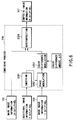
- FIG. 1 there is shown a flowchart illustrating an image information processing method according to the present invention.
- the image information processing method of the present invention will be described with reference to this flowchart.
- Additional information 101 to be embedded includes characters, images, sound, etc., which are information a creator wants to embed invisibly.
- a main image 102 is an image in which additional information is to be embedded, such as a photograph of a person's face on an identity card. The main image serves as information for producing a full-color image.
- a mask image (pattern image information) 103 is two-valued image information which is used in a combining process (step S106) and a recovery process (a) or (b) (step S109 or S112) as will be described later.
- the to-be-embedded information 101 is binary-coded (two-valued and coded).
- analog data such as sound
- digital data such as characters and images
- to-be-embedded image creating step S105 the binary (two-valued) data produced in binary coding step S104 is converted into binary image data in accordance with a predetermined format, thereby producing a to-be-embedded additional image.
- data that is usually invisible, such as sound data is converted into visible data (binary image data).
- the to-be-embedded image produced in step S105, the main image 102, and the mask image 103 are combined into a full-color composite image 107.
- the composite image 107 when made visible, apparently looks identical to the main image 102; the additional image is hidden in a state of invisibility.
- the composite image 107 can be stored in a commonly used format, for example, TIFF or JPEG.
- the composite image 107 thus produced can be distributed via either an electronic medium, such as a home page on the Internet or electronic mail, or a non-electronic medium such as paper.
- the distribution of the composite image via an electronic medium will be described.
- the composite image 107 produced in combining step S106 is recorded on an electronic medium, such as a home page or electronic mail on the Internet.
- step (a) S109 a person who received the composite image recorded on the electronic medium performs a recovery operation in step (a) S109 to make visible the additional image invisibly embedded in the composite image.
- the recipient performs a reproduction operation in step (a) S110 to reproduce the embedded additional information 101.
- the composite image 107 produced in combining step S106 is recorded on a non-electronic medium such as paper.
- a person who received the composite image 107 recorded on the non-electronic medium performs a recovery operation in step (b) S112 to make visible the additional image invisibly embedded in the composite image.
- the recipient performs a reproduction operation in step (b) S113 to reproduce the embedded additional information.
- FIG. 2 Reference will be made next to FIG. 2 to describe the method for creating the additional image to be embedded in more detail.
- step S201 the additional embedded information 101 consisting of analog data, such as sound, is converted into digital data.
- analog data such as sound
- header creation step S202 a header for the additional information is produced.
- the header contains the embedding position, the size, the type, and the attribute information for each piece of additional information.
- the header information is used when reproducing the embedded additional information.
- Table 1 below shows an example of a header for additional information to be embedded. Item Symbol Data size Header size HdrSize 4 byte Additional Information numbers St1InfoNum 2 byte Information 1 position (x, y) 1EmbPosX, 1EmbPosY 4 byte, 4 byte Information 1 size (x, y) 1EmbSizeX, 1EmbSizeY 4 byte 4 byte Information 1 type 1EmbType 2 byte ... ... ...
- the digitized to-be-embedded information and header are converted into a bilevel image using two-dimensional codes indicated below.
- the to-be-embedded information which is binary is divided from the beginning into blocks of four bits. Each block which is four bits is replaced with a black and white image region of 2 ⁇ 2 pixels as shown in FIG. 3, depending on its value.
- the upper left pixel corresponds to the least significant bit (LSB), the lower left pixel to the next high-order bit, the upper right pixel to the next high-order bit, and the lower right pixel to the most significant bit (MSB).
- to-be-embedded additional information is arranged from the beginning in hexadecimal representation as follows:
- the bilevel image information is enlarged by a factor of n in order to prevent the degradation of to-be-embedded images during a smoothing step in the combining process to be described later.
- n 2, 3 or 4.
- FIG. 5 there is shown the result of enlarging the bilevel image information of FIG. 4 by a factor of two.
- the calra code is applied to the two-dimensional coding
- a matrix type two-dimensional code or a two-dimensional bar code, such as the glyph code can be used.
- step S105 After the replacement of all the to-be-embedded additional information with two-dimensional codes, in step S105, these are laid out two-dimensionally to obtain the to-be-embedded images.
- the header a, the first information b, the second information c, the third information d, and the fourth information e are converted into two-dimensional codes.
- each piece of to-be-embedded information is related with the main image. This provides a criterion for allowing users to draw certain specific information from multiple pieces of information embedded in a composite image.
- a photograph of the owner's face is used as a main image and personal information that identifies the owner is used as to-be-embedded information.
- the personal information may be made of fingerprints or voiceprint.
- Voiceprint information can be embedded in a portion of the face photograph that corresponds with the mouth.
- the main image 102 is image information in which additional information is to be embedded and, in the case of an identity card, corresponds to an owner's face photograph.
- the image information has 24 bits of information per pixel (8 bits for each of R, G and B components).
- the to-be-embedded image 105 is a bilevel image obtained by converting additional information through the previously described technique and, in the case of an identity card, corresponds to an identification number by way of example. This information has one bit of information per pixel.
- the mask image 103 is image information used in the combining process and the embedded image recovery process and has one bit of information per pixel.
- a smoothing process is performed in step S301 with black pixels in the to-be-embedded image 105 as 1s and white pixels as 0s.
- each pair of two adjacent pixels on the periphery is set to 0s as shown in FIG. 8.
- color difference modulation step S303 on the basis of the results of the phase modulation in step S302, color difference modulation is performed in accordance with the following rules.
- the color difference amount ⁇ V is an integer in the range of 0 to 255.
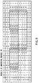
- the results for red component when all the pixel values of the main image 102 are 127, i.e., when (R, G, B) (127, 127, 127), are shown in FIG. 12.
- Each pixel value takes an integer in the range of 0 to 255.
- the red component has the maximum value of 255.
- the (0, 0) pixel and the (1, 0) pixel each have a value of 79
- the (2, 0) pixel and the (3, 0) pixel each have a value of 175. That is, in an area where no additional image is embedded, two successive pixels in which there is little red component and two successive pixels in which the red component is rich alternate.
- the color difference amount for red component is opposite in sign to those for green and blue components. Therefore, in a pixel in which the red component prevails, the green and blue components are reduced. In a pixel in which the red component is reduced, on the other hand, the other color components are increased. Green plus blue (i.e., cyan) is the complement of red. Thus, even if red and cyan are located adjacent to each other, they are difficult to recognize by human eyes and looks achromatic. Since red-rich pixels and cyan-rich pixels are alternated in units of two pixels, the human visual system cannot recognize the difference in color between pixels and hence will determine that the color difference amount is 0.
- a composite image is usually recorded on an electronic medium in a general-purpose imaging format, such as JPEG, TIFF, or the like.
- a general-purpose imaging format such as JPEG, TIFF, or the like.
- to-be-embedded information does not depend on any imaging format, not only presently available imaging formats but also formats that will be developed in future can be employed.
- the contents of a composite image are recorded on the electronic medium in such a form as shown in FIG. 12.
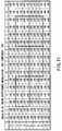
- the mask image 103 shown in FIG. 7 is used.
- the pixels of the mask image 103 are made to correspond one for one with the pixels of the composite image 107.
- the composite image is made effective in areas in which the mask image 103 takes a value of 1 or ineffective in areas in which the mask image pixels have a value of 0.
- the results are shown in FIG. 13. In this figure, shaded pixels are ineffective ones.
- the effective data pixels (shown unshaded) are cut out in a predetermined size.
- effective data is cut out in units of 4 ⁇ 4 pixels. If all the effective data pixels in a 4 ⁇ 4 pixel area take a red-rich value (175 in this example), then the embedded image in this area is made 1. If, on the other hand, they take a cyan-rich value (79 in this example), then the embedded image is made 0. When the effective data area contains both red-rich pixels and cyan-rich pixels, the embedded image depends on the pixels which are larger in number.
- the embedded image is made 1; otherwise, the embedded image is made 0. That both the red-rich pixels and the cyan-rich pixels are contained is attributed to the smoothing step in the combining process.
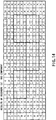
- FIG. 14 The results of recovery of the embedded image by this method are shown in FIG. 14.
- portions enclosed by bold lines corresponds to the embedded image and matches with that of FIG. 8. It thus will be seen that the embedded information can be recovered completely. Furthermore, by reversing the procedure of creating the embedded image described in conjunction with FIG. 2, the embedded information can be reproduced.
- the same method can be used to recover an embedded image.
- the non-electronic medium printed with the composite image is read by an optical reader and digitization is then performed to obtain the state of FIG. 12. After that, the embedded information is simply recovered by the same method as described above.
- Another method of reproduction can be used by which a mask sheet is physically superimposed on the composite image, which has the transmission factor distribution of the same pattern as the mask image 103 and is produced at the same recording resolution as that at the time of recording a composite image.
- This method has an advantage of requiring no troublesome operations and complex equipment in recovering embedded information.
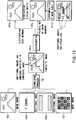
- FIG. 15 An embodiment in which copyright information and narration and associated background music (BGM) are embedded in, for example, a landscape photograph as the main image 102.
- a to-be-embedded additional image 105a uses the logotype, "T CORP.”, as the copyright information.
- a to-be-embedded additional image 105b is one into which narration (voice) for explaining the landscape photograph and appropriate BGM have been converted in accordance with the procedure of the present invention.
- An element 103 is a mask image which serves as the key to the combining and recovery processes. Note that, though not shown, the to-be-embedded images 105a and 105b are combined in advance into a single to-be-embedded image.
- the combining process according to the present invention is carried out to produce a composite image 107.
- This composite image appears simply as a landscape photograph to human eyes, but has the copyright information, narration, etc., embedded in a state of invisibility.
- the composite image is distributed over a network or through a paper medium in printed form. Depending on the contents of an image, a charge may be needed.
- the user Upon receipt of the composite image over a network by a personal computer, the user is allowed to display the composite image 107b on the display unit and to recover and reproduce the invisibly embedded narration and so on in accordance with the technique of the present invention.
- the user When receiving the composite image 107c printed in hard copy form, the user is allowed to read the composite image by means of an optical scanner and to recover and reproduce the embedded contents through the same processing as in the case of reception over a network.
- the copyright information is embedded in the distributed composite image, it can be recovered and reproduced using the same procedure as in the case of the narration, which makes it possible to make clear who has the copyright of the composite image. Even if the composite image is copied by a color copying machine, the embedded image is protected from damage or destruction. Even if, therefore, there is no optical scanner, the embedded image can be reproduced by directly superimposing a mask sheet upon the composite image as in step S112 of FIG. 15. That is, the copyright information "T CORP.” can be displayed visually. Thus, the copyright becomes obvious to everyone.
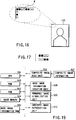
- the mask image 103 is made of checker-like patterns each of 4 ⁇ 2 pixels as shown in FIGS. 7 and 17. Of course, a pattern of 2 ⁇ 2 or 8 ⁇ 2 pixels can be used instead. It will be better to change the type of the mask image 103, depending on the time when the composite image is produced or its contents. By so doing, embedded information becomes prevented from being stolen by a third party.
- an alignment function and a function of identifying the type of the mask image 103 can be provided at the same time, which provides a very excellent system.
- this embodiment utilizes the fact that equation (4-1) is taken as equation (5) because the sensitivity of human eyes is not enough. In order to prevent embedded information from becoming known, it is better to decrease the color difference amount ⁇ V. The smaller the color difference amount ⁇ V, the smaller the absolute value of VR(i) in equation (4-1) becomes and the more difficult it is to know the embedded information.
- the composite image 107 is distributed via an electronic medium, it is relatively easy to identify the embedded information numerically even if the color difference amount ⁇ V is small.
- optical reading is required to recover the embedded image as described before. In this case, taking into consideration the performance of the optical reading means, environmental conditions, printing variations in the embedded image, etc., unless the color difference amount ⁇ V is large to some degree there arises the possibility that the embedded image is buried in noise and cannot be identified.
- the error dispersion processing decreases low-frequency components but increases high-frequency components.
- the embedded image in the composite image consists of high-frequency components.
- the error dispersion processing further increases the high-frequency components of the embedded image, which makes it more difficult for the embedded image to be identified visually.
- the processing device is constructed roughly from an image creating and recording device which creates and records a composite image on either an electronic medium or a non-electronic medium, and an image reproducing device which reproduces an embedded image from the composite image recorded on the electronic or non-electronic medium.
- a CPU central processing unit
- a ROM read-only memory
- a RAM random access memory
- An image memory 404 stores image information when images are combined and is used when processes are performed which will be described later.
- a to-be-embedded image is divided into fixed information and fluid information.
- the fixed information includes serial numbers inherent in a system and so on, whereas the fluid information includes the date and time of processing, identification numbers, voice, etc.
- the fixed information and the fluid information are entered from a to-be-embedded image ROM 409 and a to-be-embedded image input unit 410, respectively, into a to-be-embedded image creation unit 408.
- a to-be-embedded image is created in accordance with the procedure shown in FIG. 2 and then stored in the image memory 404.
- a main image 102 such as a photograph of the face of a person or a landscape photograph, is entered from a main image input unit 407 into a separate area of the image memory 404.
- the CPU 401 operates a smoothing unit 411 to perform a smoothing process on the to-be-embedded image stored in the image memory 404 and then sends the results to a phase modulation unit 412.
- the phase modulation unit 412 performs a phase modulation process as shown in FIG. 11 on the basis of the results of the smoothing process and a mask image 103 from a mask image ROM 405 and then sends the results to a color difference modulation unit 413.
- the color difference modulation unit 413 performs a color difference modulation process as shown in FIG. 11 on the basis of the results of the phase modulation process and color difference amount information from a color difference amount ROM 406 and then passes the results to a superimposition processing unit 414.
- the superimposition processing unit 414 performs a superimposition process on the results of the color difference modulation and the main image 102 stored in the image memory 404 to produce a composite image 107 and stores it into the image memory 404.
- the composite image 107 When the composite image 107 is distributed via an electronic medium, it is distributed from a composite image output unit (electronic medium) 415 via a network by way of example. In the case of distribution via a non-electronic medium, the composite image is output from a composite image output unit (non-electronic medium) 416 composed of a printer driver and a color printer. That is, the composite image 417 (107) is output in printed form.
- a CPU 501 performs the overall control of the device.
- a ROM 502 stores programs that the CPU 501 carries out to control of the operation of the entire device.
- a RAM 503 is used as a working memory of the CPU 501.
- An image memory 504 stores image information when embedded information is recovered and is used for processes which will be described later.
- the composite image reader includes an optical scanner and its driver.
- a composite image recorded on an electronic medium is directly stored into the image memory 504.
- the alignment marks M as shown in FIG. 16 are read out at the same time the composite image 507 is read and then stored in the RAM 503.
- the CPU 501 controls each unit to recover the embedded information.
- the mask image creation unit 508 identifies the type of the mask image from the alignment mark information stored in the RAM 503, takes out of the mask image ROM 505 a mask information necessary for recovery and reproduction of the embedded image, creates mask image, and stores it into the image memory 504.
- An embedded image visualization unit 509 for making visible the embedded image superimposes the mask image 103 and the composite image 507 (107) upon each other as illustrated in FIGS. 7 and 8 and extracts only the effective data of the embedded image, thereby visualizing the embedded image.
- an embedded image reproduction unit 510 performs the procedure which is the reverse of that of FIG. 2, thereby reproducing the embedded information.
- a composite image in which additional information is superimposed on a main image can be created irrespective of which of electronic and non-electronic media it is to be recorded on.
- the composite image can be recorded and added image information can be reproduced.
- multimedia contents such as electronic picture books, picture mail, sounding pictures, and so on
- multimedia contents such as electronic picture books, picture mail, sounding pictures, and so on
- the user can be identified as the owner very easily.
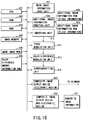
- FIG. 20 illustrates a process flow of an image information processing method according to the second embodiment.
- This flowchart is the same as that of FIG. 6 except that an achromatic coloring (discoloration) process S401 is added.
- the main image subjected to discoloration and the additional image subjected to color difference modulation in step S303 are superimposed upon each other.
- the resulting composite image has its respective pixel composed of three color components of R, G, and B.
- the main image 102 has been discolored (achromatic-colored)
- the resulting composite image also looks achromatic colors including black and white. For this reason, when the composite image is printed in auto mode by a color copying machine, the color difference information is not copied. That is, the composite image exhibits very high integrity of security.
- step S107 the composite image produced in step S304 is recorded (printed) on a recording medium such as an identity card.
- the recorded composite image has such data values as shown in FIG. 12.
- the composite image Since the composite image is blocked with the mask sheet, it is visible only through the whitened portions of the mask sheet. Thus, focusing on the whitened portions only, data values on the periphery of the embedded image are 79, while data values within the embedded image are 175. The difference between these data values, i.e., the difference in image density, allows the shape of the embedded image to be recognized visually.
- FIG. 13 shows the red component only. Likewise, the blue and green components have the differences in image density. However, since the embedded color difference amount for the red component is opposite in sign to those for the blue and green components as indicated in equations (3-1), (3-2) and (3-3), the image will appear to human eyes so that the red embedded image is embossed on the cyan background.
- the composite image looks a black and white image.
- the embedded image looks colored red and embossed on the cyan background as described above, which will have great effect on inspectors and make it easy to inspect identity cards.
- the third embodiment is intended to prevent the forgery of identity cards using the image information processing method of the second embodiment of the present invention.
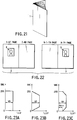
- FIG. 21 shows an example of a booklet-like identity card 1 with multiple pages.
- face photographs 4 and 5 of the owner are recorded (printed) on the first page 2 and the n-th (the last) page 3, respectively, of the identity card.
- the face photograph 4 on the first page is a common color photograph of the owner's face.
- the face photograph 5 on the last page is a variation of the face photograph 4, which is produced in such a way that the face photograph 4 is converted into a black and white image using the image information processing method of the second embodiment and then embedded with security information.
- the security information to be embedded preferably includes information associated with the owner himself or herself such as the name, the date of birth, the domicile of origin, and so on.
- the face photograph 4 on the first page is used to identify the owner (user) of the identity card, while the face photograph 5 on the last page is used to assure the face photograph 4.
- the image quality of the composite image and the strength of the security information are incompatible with each other. That is, the image quality of the composite image degrades as the security strength increases.
- the image quality and the security strength can be made compatible with each other.
- the photograph image 5 on the last page 3 appears to human eyes as a black and white image; however, since it is composed of three primary colors of R, G, and B (or C, M, and Y), it, like the photographic image 4 on the first page, can be printed out by a usual color printer. That is, the apparatus can be used in common, which is very economical.
- the identification image and the security image are used, they do not necessarily need to be printed on the first page and the last page. If, in the identity card, there exists a page which is very secure, for example, a watermarked page, the security image can be printed on that page to further increase the security.
- the security strength and the image quality are not compatible with each other as described previously.
- the image quality degrades as the security strength increases.
- causes of the degradation of image quality will be discussed.
- DESR(i), DESG(i) and DESB(i) each take an integer in the range of 0 to 255.
- an overflow results, so that 38 by which the result exceeds 255 is thrown away.
- DESR(i) 288, the embedded image should have well balanced with the composite image, so that it is placed in a state of invisibility.
- DESR(i) is limited to 255 as a result of overflow, the embedded image (security information) becomes visible.
- the color difference amount ⁇ V is fixed at Vo regardless of SRC (indicating data values of the embedded image) shown on the vertical axis as shown in FIG. 23A.
- an image information processing method and a method of preventing the forgery of identity cards and so on can be provided which provide great security against forgery without making any distinction between color image information and black and white image information.
Abstract
Description
| Item | Symbol | Data size | |
| | HdrSize | 4 byte | |
| Additional | St1InfoNum | 2 | |
| Information | |||
| 1 position (x, y) | 1EmbPosX, | 4 byte, 4 | |
| Information | |||
| 1 size (x, y) | 1EmbSizeX, | 4 | |
| Information | |||
| 1 | 1EmbType | 2 byte | |
| ... | ... | ... | |
| Information n position (x, y) | nEmbPosX, | 4 byte, 4 byte | |
| Information n size (x, y) | NEmbSizeX, | 4 byte, 4 byte | |
| Information | nEmbType | 2 byte |
Claims (10)
- An image processing method characterized by comprising the steps of:converting predetermined additional information into a visible additional image to be embedded in a main image (step S106);creating a composite image by embedding the additional image in the main image in a state of invisibility (steps S106);recording the composite image on a recording medium (steps S108, S111); andextracting the embedded additional image from the composite image recorded on the recording medium to recover the predetermined information (S110).
- The method according to claim 1, characterized in that the conversion step includes a substep of converting the additional information into visible two-valued two-dimensional codes (step S104).
- The method according to claim 1, characterized in that the conversion step includes a substep of converting the additional information into visible two-valued two-dimensional codes (step S103) and a substep of modulating the two-dimensional codes using predetermined mask pattern information (step S302), and the reproduction step includes a substep of extracting the additional image from the composite image using the mask pattern information (step S113).
- The method according to claim 1, characterized in that the conversion step includes a substep of converting the additional information into visible two-valued two-dimensional codes (step S104), a substep of smoothing the two-dimensional codes (FIG. 9), and a substep of modulating the two-dimensional codes with predetermined mask pattern information.
- The method according to claim 1, characterized in that the conversion step includes a substep of converting the additional information into visible two-valued two-dimensional codes (step S104), a substep of modulating the two-dimensional codes using predetermined mask pattern information, a substep of converting the value of each pixel of the modulated additional information into a positive or negative color difference amount for each of R, G, and B components to form three color difference modulated images for R, G, and B components (FIG. 11).
- The method according to claim 5, characterized in that the color difference amount for the R component is opposite in sign to those for the G and B components in the same pixel position on the color difference modulated images (FIG. 11).
- The method according to claim 6, characterized in that the creation step creates the composite image by superimposing the three color difference modulated images for the R, G, and B components on a full-color main image.
- The method according to claim 1, characterized by further comprising a step of converting a full-color main image into an achromatic image composed of R, G, and B components, and wherein the creation step creates the composite image in such a way that it looks black and white to the human visual system and its respective pixels is composed of multiple color components.
- The method according to claim 7, characterized in that, for pixels in a region where the additional image exhibits a maximum or minimum level of brightness, their color difference amounts are set smaller than those of other pixels, thereby preventing overflow or underflow of the composite image.
- An image processing method characterized by comprising the steps of:converting predetermined additional information into a visible additional image to be embedded in a main image;creating a composite image by embedding the additional image in the main image in a state of invisibility, the composite image is produced in such a way that it looks a black and white image to the human visual system and its respective pixel is composed of multiple color components; andrecording the composite image on a recording medium.
Applications Claiming Priority (4)
| Application Number | Priority Date | Filing Date | Title |
|---|---|---|---|
| JP9332943A JPH11168616A (en) | 1997-12-03 | 1997-12-03 | Image information processing method and image information processor |
| JP33294397 | 1997-12-03 | ||
| JP16355898 | 1998-06-11 | ||
| JP16355898A JP4015753B2 (en) | 1998-06-11 | 1998-06-11 | Image information processing method |
Publications (3)
| Publication Number | Publication Date |
|---|---|
| EP0921675A2 true EP0921675A2 (en) | 1999-06-09 |
| EP0921675A3 EP0921675A3 (en) | 2001-04-18 |
| EP0921675B1 EP0921675B1 (en) | 2006-07-05 |
Family
ID=26488954
Family Applications (1)
| Application Number | Title | Priority Date | Filing Date |
|---|---|---|---|
| EP98121556A Expired - Lifetime EP0921675B1 (en) | 1997-12-03 | 1998-11-18 | Method of processing image information and method of preventing forgery of certificates or the like |
Country Status (3)
| Country | Link |
|---|---|
| US (2) | US6438251B1 (en) |
| EP (1) | EP0921675B1 (en) |
| DE (1) | DE69835133T8 (en) |
Cited By (23)
| Publication number | Priority date | Publication date | Assignee | Title |
|---|---|---|---|---|
| EP1087611A2 (en) * | 1999-09-27 | 2001-03-28 | Eastman Kodak Company | Embedding information in a printed image |
| US6285776B1 (en) | 1994-10-21 | 2001-09-04 | Digimarc Corporation | Methods for identifying equipment used in counterfeiting |
| EP1136947A2 (en) * | 2000-03-21 | 2001-09-26 | Kabushiki Kaisha Toshiba | Information processing method |
| US6345104B1 (en) | 1994-03-17 | 2002-02-05 | Digimarc Corporation | Digital watermarks and methods for security documents |
| EP1330107A1 (en) * | 2000-09-22 | 2003-07-23 | Ricoh Company, Ltd. | Document acquiring device, document filing system, and electronic document notarizing system |
| EP1385121A1 (en) * | 2002-07-23 | 2004-01-28 | Kabushiki Kaisha Toshiba | Image processing method |
| EP1410313A1 (en) * | 2001-07-02 | 2004-04-21 | Digimarc Corporation | Hiding information out-of-phase in color channels |
| EP1014318B1 (en) * | 1998-12-18 | 2004-05-19 | Kabushiki Kaisha Toshiba | Ticket issuing method, ticket issuing system and ticket collating method |
| EP1461760A1 (en) * | 2001-11-30 | 2004-09-29 | International Barcode Corporation | System and method for validating a digital image and corresponding data |
| US6883982B2 (en) * | 2003-04-25 | 2005-04-26 | Kabushiki Kaisha Toshiba | Image processing system |
| EP1571822A1 (en) * | 2004-03-03 | 2005-09-07 | Fuji Photo Film Co., Ltd. | Print controller and printer |
| US7207491B2 (en) | 2001-11-09 | 2007-04-24 | International Barcode Corporation | System and method for generating a combined bar code image |
| FR2897487A1 (en) * | 2006-02-13 | 2007-08-17 | Adentis Sa | DIGITAL FILE MARKED BY A SUITE OF TRADEMARKS WHOSE CONCATENATION IS FORMING A MESSAGE AND METHOD OF EXTRACTING A BRAND OF SUCH A DIGITAL FILE MARK |
| US7322514B2 (en) | 2001-11-30 | 2008-01-29 | International Barcode Corporation | Method for identifying and authenticating goods using codes, barcodes and radio frequency identification |
| US7337972B2 (en) | 2001-11-09 | 2008-03-04 | International Barcode Corporation | System and method for embedding characters in a bar of a bar code |
| EP1936949A2 (en) * | 2006-12-22 | 2008-06-25 | Canon Kabushiki Kaisha | Image processing apparatus and image processing method |
| EP2028616A1 (en) | 2007-08-17 | 2009-02-25 | Kabushiki Kaisha Toshiba | Image processing method and image processing apparatus |
| EP2043041A1 (en) | 2007-09-27 | 2009-04-01 | Kabushiki Kaisha Toshiba | Image processing method and image processing device |
| US7809172B2 (en) | 2005-11-07 | 2010-10-05 | International Barcode Corporation | Method and system for generating and linking composite images |
| US7991157B2 (en) | 2006-11-16 | 2011-08-02 | Digimarc Corporation | Methods and systems responsive to features sensed from imagery or other data |
| US8126020B2 (en) | 1996-04-25 | 2012-02-28 | Digimarc Corporation | Wireless methods using signature codes |
| US8565815B2 (en) | 2006-11-16 | 2013-10-22 | Digimarc Corporation | Methods and systems responsive to features sensed from imagery or other data |
| FR3076251A1 (en) * | 2017-12-30 | 2019-07-05 | Imprimerie Nationale | METHOD FOR PROTECTING A PORTRAIT IN AN IDENTITY DOCUMENT |
Families Citing this family (69)
| Publication number | Priority date | Publication date | Assignee | Title |
|---|---|---|---|---|
| US8144368B2 (en) | 1998-01-20 | 2012-03-27 | Digimarc Coporation | Automated methods for distinguishing copies from original printed objects |
| US6763123B2 (en) | 1995-05-08 | 2004-07-13 | Digimarc Corporation | Detection of out-of-phase low visibility watermarks |
| US6721440B2 (en) | 1995-05-08 | 2004-04-13 | Digimarc Corporation | Low visibility watermarks using an out-of-phase color |
| US6718046B2 (en) | 1995-05-08 | 2004-04-06 | Digimarc Corporation | Low visibility watermark using time decay fluorescence |
| US7715446B2 (en) | 1996-04-25 | 2010-05-11 | Digimarc Corporation | Wireless methods and devices employing plural-bit data derived from audio information |
| US6965873B1 (en) | 1998-04-16 | 2005-11-15 | Digimarc Corporation | Electronic commerce using optical input device |
| JP2000106625A (en) * | 1998-07-27 | 2000-04-11 | Fuji Photo Film Co Ltd | Method and system for printing image and its storage medium |
| JP3853541B2 (en) * | 1998-07-30 | 2006-12-06 | 富士写真フイルム株式会社 | Data distribution method |
| US6731775B1 (en) * | 1998-08-18 | 2004-05-04 | Seiko Epson Corporation | Data embedding and extraction techniques for documents |
| US7536706B1 (en) * | 1998-08-24 | 2009-05-19 | Sharp Laboratories Of America, Inc. | Information enhanced audio video encoding system |
| US6628802B1 (en) * | 1999-01-29 | 2003-09-30 | International Business Machines Corporation | Marking and determining distortion in an image |
| US7164413B2 (en) * | 1999-05-19 | 2007-01-16 | Digimarc Corporation | Enhanced input peripheral |
| US6993148B1 (en) * | 1999-07-16 | 2006-01-31 | Canon Kabushiki Kaisha | Image processing apparatus and method, and storage medium |
| JP2001125846A (en) * | 1999-10-26 | 2001-05-11 | Fujitsu Ltd | Electronic device and storage medium |
| US7634089B1 (en) * | 1999-10-29 | 2009-12-15 | Sarnoff Corporation | Cinema anti-piracy measures |
| JP3976969B2 (en) * | 1999-12-02 | 2007-09-19 | キヤノン株式会社 | Image processing apparatus, image processing method, and storage medium |
| US7738673B2 (en) * | 2000-04-19 | 2010-06-15 | Digimarc Corporation | Low visible digital watermarks |
| US8027509B2 (en) | 2000-04-19 | 2011-09-27 | Digimarc Corporation | Digital watermarking in data representing color channels |
| US6912295B2 (en) | 2000-04-19 | 2005-06-28 | Digimarc Corporation | Enhancing embedding of out-of-phase signals |
| US6804377B2 (en) | 2000-04-19 | 2004-10-12 | Digimarc Corporation | Detecting information hidden out-of-phase in color channels |
| US6572025B1 (en) * | 2000-05-10 | 2003-06-03 | Japan Gain The Summit Co., Ltd. | Information code product, manufacturing device and method for manufacturing the same, information code reading device, authentication system, authentication terminal, authentication server, and authentication method |
| US7162035B1 (en) | 2000-05-24 | 2007-01-09 | Tracer Detection Technology Corp. | Authentication method and system |
| US6813367B1 (en) * | 2000-09-11 | 2004-11-02 | Seiko Epson Corporation | Method and apparatus for site selection for data embedding |
| EP1317734B1 (en) * | 2000-09-15 | 2005-02-16 | Trustcopy Pte Ltd | Optical watermark |
| US7162460B2 (en) * | 2000-10-10 | 2007-01-09 | Stamps.Com Inc | Media type identification |
| US8103877B2 (en) * | 2000-12-21 | 2012-01-24 | Digimarc Corporation | Content identification and electronic tickets, coupons and credits |
| US6965683B2 (en) * | 2000-12-21 | 2005-11-15 | Digimarc Corporation | Routing networks for use with watermark systems |
| US20020178362A1 (en) * | 2001-05-10 | 2002-11-28 | Kwon Oh-Jin | Method fo embedding hidden digital watermark into subband-decomposed image for identification of copyrighter |
| US8094869B2 (en) | 2001-07-02 | 2012-01-10 | Digimarc Corporation | Fragile and emerging digital watermarks |
| US7537170B2 (en) | 2001-08-31 | 2009-05-26 | Digimarc Corporation | Machine-readable security features for printed objects |
| US7213757B2 (en) | 2001-08-31 | 2007-05-08 | Digimarc Corporation | Emerging security features for identification documents |
| US7188778B2 (en) * | 2001-09-17 | 2007-03-13 | Codemagic | Machine-readable symbol and related method |
| DK1456810T3 (en) | 2001-12-18 | 2011-07-18 | L 1 Secure Credentialing Inc | Multiple image security features to identify documents and methods of producing them |
| TWI235926B (en) | 2002-01-11 | 2005-07-11 | Sonix Technology Co Ltd | A method for producing indicators and processing system, coordinate positioning system and electronic book system utilizing the indicators |
| JP4143441B2 (en) * | 2002-04-24 | 2008-09-03 | キヤノン株式会社 | Information processing method and apparatus, computer program, and computer-readable storage medium |
| US7824029B2 (en) | 2002-05-10 | 2010-11-02 | L-1 Secure Credentialing, Inc. | Identification card printer-assembler for over the counter card issuing |
| WO2004029871A1 (en) | 2002-09-26 | 2004-04-08 | Kenji Yoshida | Information reproduction/i/o method using dot pattern, information reproduction device, mobile information i/o device, and electronic toy |
| US7230740B2 (en) * | 2002-11-25 | 2007-06-12 | Hewlett-Packard Development Company, L.P. | Substantial preclusion of output of pixels for other color components upon output of pixel for image pixel color component |
| US7076083B2 (en) * | 2002-12-12 | 2006-07-11 | Eastman Kodak Company | Personnel access control system |
| US7225991B2 (en) * | 2003-04-16 | 2007-06-05 | Digimarc Corporation | Three dimensional data storage |
| JP4036333B2 (en) * | 2003-05-23 | 2008-01-23 | 日本アイ・ビー・エム株式会社 | Sender mail server, receiver mail server, e-mail system, signature data management method, and program |
| JP3693666B2 (en) * | 2003-09-11 | 2005-09-07 | シャープ株式会社 | Image processing apparatus, image forming apparatus, and image processing method |
| US7421581B2 (en) * | 2003-09-30 | 2008-09-02 | Graphic Security Systems Corporation | Method and system for controlling encoded image production |
| JP3943073B2 (en) * | 2003-11-28 | 2007-07-11 | 富士通株式会社 | Image data processing apparatus, image data processing method, and image data processing program |
| JP4167590B2 (en) * | 2003-12-22 | 2008-10-15 | 株式会社東芝 | Image processing method |
| US20050203872A1 (en) * | 2004-03-05 | 2005-09-15 | Kwong Kwan John M. | Method and apparatus making, operating and using media parsers to mark, read, and unmark instances of media formats supporting one, two and multi-dimensional instances and data streams |
| JP4660212B2 (en) * | 2005-01-24 | 2011-03-30 | 株式会社東芝 | Image processing apparatus and image processing method |
| KR100707689B1 (en) | 2005-04-21 | 2007-04-16 | 퍼스텍주식회사 | System and method for verifying faces by individual standard difference |
| CN101167084B (en) | 2005-04-28 | 2010-05-12 | 吉田健治 | Information I/O method using dot pattern |
| JP4569382B2 (en) * | 2005-05-20 | 2010-10-27 | ブラザー工業株式会社 | PRINT DATA EDITING DEVICE, PRINT DATA EDITING PROGRAM, AND RECORDING MEDIUM |
| JP4687263B2 (en) * | 2005-06-13 | 2011-05-25 | 富士ゼロックス株式会社 | Encoding device, decoding device, encoding method, decoding method, and programs thereof |
| JP2006352628A (en) * | 2005-06-17 | 2006-12-28 | Viva Computer Co Ltd | Digital image generating/transmitting/receiving apparatus and distribution and reproducing system thereof |
| US8107099B2 (en) * | 2005-06-24 | 2012-01-31 | Xerox Corporation | Watermarking |
| JP3771252B1 (en) | 2005-07-01 | 2006-04-26 | 健治 吉田 | Dot pattern |
| US20070074029A1 (en) * | 2005-09-28 | 2007-03-29 | Kabushiki Kaisha Toshiba | Data embedding apparatus |
| US8797389B2 (en) * | 2007-02-22 | 2014-08-05 | Nec Corporation | Image processing apparatus, method and program, and display apparatus |
| US8325970B2 (en) * | 2007-03-19 | 2012-12-04 | Ricoh Company, Limited | Apparatus, method, and computer product for image processing |
| US20090244558A1 (en) * | 2008-03-25 | 2009-10-01 | Kabushiki Kaisha Toshiba | Image processing apparatus and image processing method |
| US7995196B1 (en) | 2008-04-23 | 2011-08-09 | Tracer Detection Technology Corp. | Authentication method and system |
| US8254785B1 (en) * | 2008-05-15 | 2012-08-28 | Sprint Communications Company L.P. | Optical image processing to wirelessly transfer a voice message |
| CN101753473B (en) * | 2008-12-09 | 2012-08-08 | 宏碁股份有限公司 | Method for instantaneously transmitting interactive image and system using method |
| US9117268B2 (en) | 2008-12-17 | 2015-08-25 | Digimarc Corporation | Out of phase digital watermarking in two chrominance directions |
| US8199969B2 (en) | 2008-12-17 | 2012-06-12 | Digimarc Corporation | Out of phase digital watermarking in two chrominance directions |
| US9159112B2 (en) * | 2010-09-16 | 2015-10-13 | Hewlett-Packard Development Company, L.P. | Digital watermarking using saturation patterns |
| US8903120B1 (en) * | 2011-12-21 | 2014-12-02 | Symantec Corporation | System and method for providing an image having an embedded matrix code |
| US9227428B2 (en) * | 2012-06-19 | 2016-01-05 | Electronics For Imaging, Inc. | Simulated embossing and imprinting |
| US10249015B2 (en) * | 2013-08-28 | 2019-04-02 | Morphotrust Usa, Llc | System and method for digitally watermarking digital facial portraits |
| US11582202B2 (en) | 2015-02-16 | 2023-02-14 | Arebus, LLC | System, method and application for transcoding data into media files |
| WO2020018022A1 (en) * | 2018-07-19 | 2020-01-23 | Secur3Dp+ Pte. Ltd. | Method of additive manufacturing of object using object material, object manufactured using the same, and method of scanning an object identifier formed using the same |
Citations (3)
| Publication number | Priority date | Publication date | Assignee | Title |
|---|---|---|---|---|
| EP0554115A1 (en) * | 1992-01-31 | 1993-08-04 | Canon Kabushiki Kaisha | Image processing method and apparatus |
| WO1995014289A2 (en) * | 1993-11-18 | 1995-05-26 | Pinecone Imaging Corporation | Identification/authentication coding method and apparatus |
| JPH09248935A (en) * | 1996-03-14 | 1997-09-22 | Toshiba Corp | Image recording and reproducing device |
Family Cites Families (23)
| Publication number | Priority date | Publication date | Assignee | Title |
|---|---|---|---|---|
| US3067659A (en) * | 1959-04-30 | 1962-12-11 | Paul W Schwimmer | Method of making indentification cards with pictures |
| GB2196167B (en) * | 1986-10-01 | 1991-01-02 | Emi Plc Thorn | Apparatus for marking a recorded signal |
| JP2756280B2 (en) * | 1988-11-14 | 1998-05-25 | キヤノン株式会社 | Color image processing equipment |
| IL91221A (en) * | 1989-08-04 | 1995-03-30 | Ibm Israel | Method for the compression of binary text |
| US5169155A (en) * | 1990-03-29 | 1992-12-08 | Technical Systems Corp. | Coded playing cards and other standardized documents |
| US5522623A (en) * | 1990-03-29 | 1996-06-04 | Technical Systems Corp. | Coded identification card and other standardized documents |
| NL192610C (en) * | 1990-12-13 | 1997-11-04 | Enschede & Zonen Grafisch | Image carrier and method for printing an image on an image carrier. |
| US5369261A (en) * | 1992-02-12 | 1994-11-29 | Shamir; Harry | Multi-color information encoding system |
| US5502576A (en) * | 1992-08-24 | 1996-03-26 | Ramsay International Corporation | Method and apparatus for the transmission, storage, and retrieval of documents in an electronic domain |
| US5449200A (en) * | 1993-06-08 | 1995-09-12 | Domtar, Inc. | Security paper with color mark |
| US5636292C1 (en) * | 1995-05-08 | 2002-06-18 | Digimarc Corp | Steganography methods employing embedded calibration data |
| US5493677A (en) * | 1994-06-08 | 1996-02-20 | Systems Research & Applications Corporation | Generation, archiving, and retrieval of digital images with evoked suggestion-set captions and natural language interface |
| US6053405A (en) * | 1995-06-07 | 2000-04-25 | Panda Eng., Inc. | Electronic verification machine for documents |
| US5530759A (en) * | 1995-02-01 | 1996-06-25 | International Business Machines Corporation | Color correct digital watermarking of images |
| US5727092A (en) * | 1995-05-17 | 1998-03-10 | The Regents Of The University Of California | Compression embedding |
| US5613004A (en) * | 1995-06-07 | 1997-03-18 | The Dice Company | Steganographic method and device |
| US6006328A (en) * | 1995-07-14 | 1999-12-21 | Christopher N. Drake | Computer software authentication, protection, and security system |
| EP0766468B1 (en) * | 1995-09-28 | 2006-05-03 | Nec Corporation | Method and system for inserting a spread spectrum watermark into multimedia data |
| US6095566A (en) * | 1996-03-14 | 2000-08-01 | Kabushiki Kaisha Toshiba | Image recorded product, image recording system, image reproducing system, and recording medium for use to superimpose-record/reproduce additional information |
| US5974548A (en) * | 1996-07-12 | 1999-10-26 | Novell, Inc. | Media-independent document security method and apparatus |
| US5825892A (en) * | 1996-10-28 | 1998-10-20 | International Business Machines Corporation | Protecting images with an image watermark |
| US5974150A (en) * | 1997-09-30 | 1999-10-26 | Tracer Detection Technology Corp. | System and method for authentication of goods |
| US5946414A (en) * | 1998-08-28 | 1999-08-31 | Xerox Corporation | Encoding data in color images using patterned color modulated image regions |
-
1998
- 1998-11-18 DE DE69835133T patent/DE69835133T8/en active Active
- 1998-11-18 EP EP98121556A patent/EP0921675B1/en not_active Expired - Lifetime
- 1998-12-02 US US09/203,562 patent/US6438251B1/en not_active Expired - Lifetime
-
2002
- 2002-06-11 US US10/166,165 patent/US6724921B2/en not_active Expired - Lifetime
Patent Citations (3)
| Publication number | Priority date | Publication date | Assignee | Title |
|---|---|---|---|---|
| EP0554115A1 (en) * | 1992-01-31 | 1993-08-04 | Canon Kabushiki Kaisha | Image processing method and apparatus |
| WO1995014289A2 (en) * | 1993-11-18 | 1995-05-26 | Pinecone Imaging Corporation | Identification/authentication coding method and apparatus |
| JPH09248935A (en) * | 1996-03-14 | 1997-09-22 | Toshiba Corp | Image recording and reproducing device |
Cited By (43)
| Publication number | Priority date | Publication date | Assignee | Title |
|---|---|---|---|---|
| US6345104B1 (en) | 1994-03-17 | 2002-02-05 | Digimarc Corporation | Digital watermarks and methods for security documents |
| US6285776B1 (en) | 1994-10-21 | 2001-09-04 | Digimarc Corporation | Methods for identifying equipment used in counterfeiting |
| US6427020B1 (en) | 1995-05-08 | 2002-07-30 | Digimarc Corporation | Methods and devices for recognizing banknotes and responding accordingly |
| US8126020B2 (en) | 1996-04-25 | 2012-02-28 | Digimarc Corporation | Wireless methods using signature codes |
| EP1014318B1 (en) * | 1998-12-18 | 2004-05-19 | Kabushiki Kaisha Toshiba | Ticket issuing method, ticket issuing system and ticket collating method |
| EP1087611A3 (en) * | 1999-09-27 | 2002-05-02 | Eastman Kodak Company | Embedding information in a printed image |
| EP1087611A2 (en) * | 1999-09-27 | 2001-03-28 | Eastman Kodak Company | Embedding information in a printed image |
| EP1136947A2 (en) * | 2000-03-21 | 2001-09-26 | Kabushiki Kaisha Toshiba | Information processing method |
| US6885755B2 (en) | 2000-03-21 | 2005-04-26 | Kabushiki Kaisha Toshiba | Information processing method |
| EP1136947A3 (en) * | 2000-03-21 | 2003-11-26 | Kabushiki Kaisha Toshiba | Information processing method |
| EP1330107A1 (en) * | 2000-09-22 | 2003-07-23 | Ricoh Company, Ltd. | Document acquiring device, document filing system, and electronic document notarizing system |
| EP1330107A4 (en) * | 2000-09-22 | 2006-10-18 | Ricoh Kk | Document acquiring device, document filing system, and electronic document notarizing system |
| EP2352111A1 (en) * | 2001-07-02 | 2011-08-03 | Digimarc Corporation | Hiding information in colour channels with reduced visibility |
| EP1410313A4 (en) * | 2001-07-02 | 2010-12-22 | Digimarc Corp | Hiding information out-of-phase in color channels |
| EP1410313A1 (en) * | 2001-07-02 | 2004-04-21 | Digimarc Corporation | Hiding information out-of-phase in color channels |
| US7207491B2 (en) | 2001-11-09 | 2007-04-24 | International Barcode Corporation | System and method for generating a combined bar code image |
| US7337972B2 (en) | 2001-11-09 | 2008-03-04 | International Barcode Corporation | System and method for embedding characters in a bar of a bar code |
| US7322514B2 (en) | 2001-11-30 | 2008-01-29 | International Barcode Corporation | Method for identifying and authenticating goods using codes, barcodes and radio frequency identification |
| EP1461760A1 (en) * | 2001-11-30 | 2004-09-29 | International Barcode Corporation | System and method for validating a digital image and corresponding data |
| EP1461760A4 (en) * | 2001-11-30 | 2007-02-21 | Int Barcode Corp | System and method for validating a digital image and corresponding data |
| EP1494168A2 (en) * | 2002-07-23 | 2005-01-05 | Kabushiki Kaisha Toshiba | Image processing method |
| US6901862B2 (en) | 2002-07-23 | 2005-06-07 | Kabushiki Kaisha Toshiba | Image processing method |
| EP1494168A3 (en) * | 2002-07-23 | 2006-08-23 | Kabushiki Kaisha Toshiba | Image processing method |
| EP1385121A1 (en) * | 2002-07-23 | 2004-01-28 | Kabushiki Kaisha Toshiba | Image processing method |
| US7489800B2 (en) | 2002-07-23 | 2009-02-10 | Kabushiki Kaisha Toshiba | Image processing method |
| US6883982B2 (en) * | 2003-04-25 | 2005-04-26 | Kabushiki Kaisha Toshiba | Image processing system |
| US7483157B2 (en) | 2004-03-03 | 2009-01-27 | Fujifilm Corporation | Print controller and printer |
| EP1571822A1 (en) * | 2004-03-03 | 2005-09-07 | Fuji Photo Film Co., Ltd. | Print controller and printer |
| US7809172B2 (en) | 2005-11-07 | 2010-10-05 | International Barcode Corporation | Method and system for generating and linking composite images |
| FR2897487A1 (en) * | 2006-02-13 | 2007-08-17 | Adentis Sa | DIGITAL FILE MARKED BY A SUITE OF TRADEMARKS WHOSE CONCATENATION IS FORMING A MESSAGE AND METHOD OF EXTRACTING A BRAND OF SUCH A DIGITAL FILE MARK |
| WO2007093728A3 (en) * | 2006-02-13 | 2007-11-08 | Adentis | Digital file marked by a series of marks the concatenation of which forms a message and method for extracting a mark from such a digital file |
| WO2007093728A2 (en) * | 2006-02-13 | 2007-08-23 | Adentis | Digital file marked by a series of marks the concatenation of which forms a message and method for extracting a mark from such a digital file |
| US8565815B2 (en) | 2006-11-16 | 2013-10-22 | Digimarc Corporation | Methods and systems responsive to features sensed from imagery or other data |
| US7991157B2 (en) | 2006-11-16 | 2011-08-02 | Digimarc Corporation | Methods and systems responsive to features sensed from imagery or other data |
| EP1936949A2 (en) * | 2006-12-22 | 2008-06-25 | Canon Kabushiki Kaisha | Image processing apparatus and image processing method |
| US7952750B2 (en) | 2006-12-22 | 2011-05-31 | Canon Kabushiki Kaisha | Image processing apparatus and image processing method |
| EP1936949A3 (en) * | 2006-12-22 | 2009-07-08 | Canon Kabushiki Kaisha | Image processing apparatus and image processing method |
| EP2146313A1 (en) * | 2007-08-17 | 2010-01-20 | Kabushi Kaisha Toshiba | Image processing method and image processing apparatus |
| US8175323B2 (en) | 2007-08-17 | 2012-05-08 | Kabushiki Kaisha Toshiba | Image processing method and image processing apparatus |
| EP2028616A1 (en) | 2007-08-17 | 2009-02-25 | Kabushiki Kaisha Toshiba | Image processing method and image processing apparatus |
| EP2043041A1 (en) | 2007-09-27 | 2009-04-01 | Kabushiki Kaisha Toshiba | Image processing method and image processing device |
| US8320607B2 (en) | 2007-09-27 | 2012-11-27 | Kabushiki Kaisha Toshiba | Image processing method and image processing device for embedding invisible sub information into main images |
| FR3076251A1 (en) * | 2017-12-30 | 2019-07-05 | Imprimerie Nationale | METHOD FOR PROTECTING A PORTRAIT IN AN IDENTITY DOCUMENT |
Also Published As
| Publication number | Publication date |
|---|---|
| DE69835133T2 (en) | 2007-02-08 |
| DE69835133D1 (en) | 2006-08-17 |
| US6724921B2 (en) | 2004-04-20 |
| DE69835133T8 (en) | 2007-05-16 |
| EP0921675B1 (en) | 2006-07-05 |
| US20020181025A1 (en) | 2002-12-05 |
| US6438251B1 (en) | 2002-08-20 |
| EP0921675A3 (en) | 2001-04-18 |
Similar Documents
| Publication | Publication Date | Title |
|---|---|---|
| EP0921675B1 (en) | Method of processing image information and method of preventing forgery of certificates or the like | |
| EP1014318B1 (en) | Ticket issuing method, ticket issuing system and ticket collating method | |
| JP4495824B2 (en) | Information processing method | |
| US6095566A (en) | Image recorded product, image recording system, image reproducing system, and recording medium for use to superimpose-record/reproduce additional information | |
| JP3373811B2 (en) | Method and apparatus for embedding and detecting watermark information in black and white binary document image | |
| EP1591953B1 (en) | System and method for decoding digital encoded images | |
| CN1952976B (en) | Improved techniques for detecting, analyzing and using visible authentication patterns | |
| US6978035B2 (en) | Information hiding system, method, and printed matter into which information is hidden | |
| US7197161B2 (en) | Embedding information in images using two-layer conjugate screening | |
| US20080028221A1 (en) | Additional Information Processing Apparatus, Additional Information Processing System, and Additional Information Processing Method | |
| KR100547794B1 (en) | Image processing method | |
| US20070003341A1 (en) | Image processing device, image processing method, program, and recording medium | |
| US20090087020A1 (en) | Image processing method and image processing device | |
| US6636614B1 (en) | Method for preventing the falsification of documents comprising a photograph, preferably a facial-view photograph | |
| JP2005102264A (en) | Method for embedding screen code capable of storing large amount of data on paper | |
| JP3853541B2 (en) | Data distribution method | |
| JPH11168616A (en) | Image information processing method and image information processor | |
| JP4015753B2 (en) | Image information processing method | |
| JPH09179494A (en) | Confidential information recording method | |
| JP2001126046A (en) | Ic card, ic card authentication system and its authentication method | |
| JP2005159438A (en) | Image processing method | |
| JP2001094755A (en) | Image processing method | |
| JPH09251522A (en) | Recorded matter and recording/reproducing device | |
| JP4829164B2 (en) | Image processing apparatus and image processing method | |
| JPH09154007A (en) | Secret information recording method |
Legal Events
| Date | Code | Title | Description |
|---|---|---|---|
| PUAI | Public reference made under article 153(3) epc to a published international application that has entered the european phase |
Free format text: ORIGINAL CODE: 0009012 |
|
| 17P | Request for examination filed |
Effective date: 19981118 |
|
| AK | Designated contracting states |
Kind code of ref document: A2 Designated state(s): DE FR GB |
|
| AX | Request for extension of the european patent |
Free format text: AL;LT;LV;MK;RO;SI |
|
| PUAL | Search report despatched |
Free format text: ORIGINAL CODE: 0009013 |
|
| AK | Designated contracting states |
Kind code of ref document: A3 Designated state(s): AT BE CH CY DE DK ES FI FR GB GR IE IT LI LU MC NL PT SE |
|
| AX | Request for extension of the european patent |
Free format text: AL;LT;LV;MK;RO;SI |
|
| AKX | Designation fees paid |
Free format text: DE FR GB |
|
| 17Q | First examination report despatched |
Effective date: 20030813 |
|
| GRAP | Despatch of communication of intention to grant a patent |
Free format text: ORIGINAL CODE: EPIDOSNIGR1 |
|
| RIN1 | Information on inventor provided before grant (corrected) |
Inventor name: YAMAGUCHI, TAKASHI,KABUSHIKI KAISHA TOSHIBA |
|
| GRAS | Grant fee paid |
Free format text: ORIGINAL CODE: EPIDOSNIGR3 |
|
| GRAA | (expected) grant |
Free format text: ORIGINAL CODE: 0009210 |
|
| AK | Designated contracting states |
Kind code of ref document: B1 Designated state(s): DE FR GB |
|
| REG | Reference to a national code |
Ref country code: GB Ref legal event code: FG4D |
|
| REF | Corresponds to: |
Ref document number: 69835133 Country of ref document: DE Date of ref document: 20060817 Kind code of ref document: P |
|
| PGFP | Annual fee paid to national office [announced via postgrant information from national office to epo] |
Ref country code: GB Payment date: 20061115 Year of fee payment: 9 |
|
| ET | Fr: translation filed | ||
| PLBE | No opposition filed within time limit |
Free format text: ORIGINAL CODE: 0009261 |
|
| STAA | Information on the status of an ep patent application or granted ep patent |
Free format text: STATUS: NO OPPOSITION FILED WITHIN TIME LIMIT |
|
| 26N | No opposition filed |
Effective date: 20070410 |
|
| GBPC | Gb: european patent ceased through non-payment of renewal fee |
Effective date: 20071118 |
|
| PG25 | Lapsed in a contracting state [announced via postgrant information from national office to epo] |
Ref country code: GB Free format text: LAPSE BECAUSE OF NON-PAYMENT OF DUE FEES Effective date: 20071118 |
|
| REG | Reference to a national code |
Ref country code: FR Ref legal event code: PLFP Year of fee payment: 18 |
|
| REG | Reference to a national code |
Ref country code: FR Ref legal event code: PLFP Year of fee payment: 19 |
|
| REG | Reference to a national code |
Ref country code: FR Ref legal event code: PLFP Year of fee payment: 20 |
|
| PGFP | Annual fee paid to national office [announced via postgrant information from national office to epo] |
Ref country code: FR Payment date: 20171012 Year of fee payment: 20 Ref country code: DE Payment date: 20171114 Year of fee payment: 20 |
|
| REG | Reference to a national code |
Ref country code: DE Ref legal event code: R071 Ref document number: 69835133 Country of ref document: DE |