EP0923187A2 - Alternator for a vehicle - Google Patents
Alternator for a vehicle Download PDFInfo
- Publication number
- EP0923187A2 EP0923187A2 EP98123192A EP98123192A EP0923187A2 EP 0923187 A2 EP0923187 A2 EP 0923187A2 EP 98123192 A EP98123192 A EP 98123192A EP 98123192 A EP98123192 A EP 98123192A EP 0923187 A2 EP0923187 A2 EP 0923187A2
- Authority
- EP
- European Patent Office
- Prior art keywords
- stator
- conductor segments
- disposed
- portions
- connected portions
- Prior art date
- Legal status (The legal status is an assumption and is not a legal conclusion. Google has not performed a legal analysis and makes no representation as to the accuracy of the status listed.)
- Granted
Links
Images


Classifications
-
- H—ELECTRICITY
- H02—GENERATION; CONVERSION OR DISTRIBUTION OF ELECTRIC POWER
- H02K—DYNAMO-ELECTRIC MACHINES
- H02K3/00—Details of windings
- H02K3/04—Windings characterised by the conductor shape, form or construction, e.g. with bar conductors
- H02K3/28—Layout of windings or of connections between windings
-
- H—ELECTRICITY
- H02—GENERATION; CONVERSION OR DISTRIBUTION OF ELECTRIC POWER
- H02K—DYNAMO-ELECTRIC MACHINES
- H02K19/00—Synchronous motors or generators
- H02K19/16—Synchronous generators
- H02K19/22—Synchronous generators having windings each turn of which co-operates alternately with poles of opposite polarity, e.g. heteropolar generators
-
- H—ELECTRICITY
- H02—GENERATION; CONVERSION OR DISTRIBUTION OF ELECTRIC POWER
- H02K—DYNAMO-ELECTRIC MACHINES
- H02K3/00—Details of windings
- H02K3/04—Windings characterised by the conductor shape, form or construction, e.g. with bar conductors
- H02K3/12—Windings characterised by the conductor shape, form or construction, e.g. with bar conductors arranged in slots
-
- H—ELECTRICITY
- H02—GENERATION; CONVERSION OR DISTRIBUTION OF ELECTRIC POWER
- H02K—DYNAMO-ELECTRIC MACHINES
- H02K3/00—Details of windings
- H02K3/04—Windings characterised by the conductor shape, form or construction, e.g. with bar conductors
- H02K3/24—Windings characterised by the conductor shape, form or construction, e.g. with bar conductors with channels or ducts for cooling medium between the conductors
-
- H—ELECTRICITY
- H02—GENERATION; CONVERSION OR DISTRIBUTION OF ELECTRIC POWER
- H02K—DYNAMO-ELECTRIC MACHINES
- H02K3/00—Details of windings
- H02K3/46—Fastening of windings on the stator or rotor structure
- H02K3/50—Fastening of winding heads, equalising connectors, or connections thereto
-
- H—ELECTRICITY
- H02—GENERATION; CONVERSION OR DISTRIBUTION OF ELECTRIC POWER
- H02K—DYNAMO-ELECTRIC MACHINES
- H02K9/00—Arrangements for cooling or ventilating
- H02K9/02—Arrangements for cooling or ventilating by ambient air flowing through the machine
- H02K9/04—Arrangements for cooling or ventilating by ambient air flowing through the machine having means for generating a flow of cooling medium
- H02K9/06—Arrangements for cooling or ventilating by ambient air flowing through the machine having means for generating a flow of cooling medium with fans or impellers driven by the machine shaft
-
- H—ELECTRICITY
- H02—GENERATION; CONVERSION OR DISTRIBUTION OF ELECTRIC POWER
- H02K—DYNAMO-ELECTRIC MACHINES
- H02K7/00—Arrangements for handling mechanical energy structurally associated with dynamo-electric machines, e.g. structural association with mechanical driving motors or auxiliary dynamo-electric machines
- H02K7/10—Structural association with clutches, brakes, gears, pulleys or mechanical starters
- H02K7/1004—Structural association with clutches, brakes, gears, pulleys or mechanical starters with pulleys
- H02K7/1008—Structural association with clutches, brakes, gears, pulleys or mechanical starters with pulleys structurally associated with the machine rotor
Definitions
- the present invention relates to a stator of a vehicle alternator.
- An alternator disclosed in JP-A-3-235644 has a pair of cooling fans fixed to opposite sides of a rotor.
- the pair of inner cooling fans take cooling air into frames and discharge the cooling air from windows formed in the circumferential surface of the frames, thereby cooling the stator winding.
- U.S.P. 1,822,261 and WO92/06527 disclose a plurality of U-shaped conductor segments welded to form a stator winding.
- sharp edges may be formed on the welded portions. Such edges may cause concentration of mechanical stress and electrochemical stress, thereby resulting in mechanical breakdown or electrochemical corrosion.
- dust or foreign particles introduced with the cooling air may accumulate on the edges if such a stator winding is cooled by such a inner cooling fans. If salt water is introduced by the inner cooling fans, insulation members disposed in the stator may be deteriorated.
- the present invention is to prevent such mechanical and electrochemical troubles on the connected portion of conductor segments forming a stator winding.
- the stator winding is composed of a plurality of conductor segments having end portions extending in the opposite direction to each other and a plurality of ball-shaped connected portion between the conductor segments to form continuously connected coils.
- Each of the ball-shaped connected portions includes one end of one conductor segment and the other end of another conductor segment.
- the ball-shaped connected portions are disposed at the same end of said stator core.
- Each of the conductor segments can have a U-shaped portion.
- the conductor segments is preferably welded by a non-contact type welder, such as a tungsten inert gas (TIG) welder, to form the connected portions into a ball shape.
- a non-contact type welder such as a tungsten inert gas (TIG) welder
- a stator of a vehicle alternator according to a first embodiment of the invention is described with reference to Figs. 1- 6.
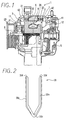
- vehicle alternator 1 is composed of stator 2, rotor 3, a pair of frames 4, rectifier 5 and others.
- Stator 2 is composed of stator core 32, a plurality of conductor segments 33 forming a stator winding and insulator 34 disposed between stator core 32 and the conductor segments 33.
- Stator core 32 is a laminate of cylindrical thin steel sheets which has a plurality of slots in the inner periphery thereof.
- Conductor segments 33 extend from stator core 32 to form coil ends 31.
- Rotor 3 is composed of cylindrically-wound-and-insulated field coil 8, a pair of pole cores 7 respectively having six claw poles which enclose field coil therebetween and shaft 6 press-fitted to the pair of cores 7.
- Rotor 3 has a mixed flow type cooling fan 11 at the front end thereof to supply cooling air from front portions of the rotor in the axial and radial directions and a centrifugal type cooling fan 12 at the rear end thereof to supply cooling air from rear portions of the rotor in the radial direction.
- the pair of frames 4 accommodates and supports stator 2 and rotor 3 so that rotor 3 can rotate about shaft 6 and stator core 2 can be disposed around circumference of rotor 3 at a certain air gap.
- the pair of frames 4 has air-discharge windows 42 at the portions thereof opposite to coil ends 31 of stator 2 and air-intake windows 41 at the axially opposite surfaces thereof.
- Vehicle alternator 1 is driven to rotate by an engine (not shown) via pulley 20 and a belt.
- field coil 8 is supplied with exciting current
- the claw poles of the pair of pole cores 7 are excited to generate three-phase ac voltage in the stator winding, and dc power is supplied from output terminals of rectifier 5.
- each of U-shaped copper conductor segments 33 has U-turn portion 33c, inner-portion 33a to be disposed in one of slots 35 at a circumference inside U-turn portion 33c and outer-portion 33b to be disposed in another of slots 35 at a circumference outside U-turn portion 33c.
- Each of inner-portion 33a and outer-portion 33b has a straight portion to be disposed in one of slots 35 and a portion to extend outward from the one of slots 35.
- both inner-portion 33a and outer-portion 33b have a rectangular cross-section with the radial sides being longer than the circumferential sides. Because conductor segments 33 are not coated with insulating material, S-shaped insulator 34 is disposed in each of slots 35 to insulate two conductor segments from each other.
- U-turn portions 33c are disposed at the same end of stator core 32.
- Inclined portions 33e extending left are formed from outer-portion 33b, and inclined portions 33e extending right are formed from inner-portion 33a to form uniform coil ends 31.
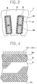
- Each of connected portions 33f is formed to join another as shown in Fig. 5A.
- Joining end portions 33d are welded together by a contactless type welder such as a tungsten inert-gas welder (hereinafter referred to as the TIG welder) so that only limited area of end portions can be melted to form ball-shaped or raindrop-shaped connected portions 33f.
- the TIG welder discharges arc current between a tungsten electrode and a base metal member in an inert gas to melt the base metal member and a filler metal member for welding.
- the TIG welder can control quantity of heat and quantity of filler material separately.
- End portions 33d of neighboring conductor segments 33 are put side by side, and a nozzle having a tungsten electrode is brought near the end portions 33d to be welded by the TIG welder.
- each of connected portions 33f is melted wide enough to form into a raindrop-shaped ball without any edge due to surface tension as shown in Fig. 5B.
- Each of connected portions 33f becomes larger than conductor segment 33 both in thickness (T > t) and in width (W > 2w).
- T > t thickness
- W > 2w width
- the edge-less ball-shaped portions are free from concentration of stresses and corrosion.
- the ball-shaped surface of the connected portion 33f is coated evenly with resinous film 33g for protection and insulation as shown in Fig. 5C.
- the stator winding is formed as follows. U-shaped conductor segments 33 are inserted into respective slots 35 of stator 2 so that U-turn portions 33c are disposed on the same axial end of stator core 32, so that outer-portions 33b are disposed at the inner portion of slots 35 (or an outer circumference of stator core 32), and inner-portion 33a are disposed in the outlet portion of slots 35 (or an inner circumference of stator core 32) as shown in Fig. 3.
- Each of conductor segments 33 is manufactured as follows. A copper plate is bent and press-formed into a U-shape so that opposite sides of outer-portion 33b and inner-portion 33a are inserted in one of slots 35 to be in contact with the parallel side walls of one of slots 33 via insulator 34.
- each of two end portions 33d of one of conductor segments 33 is bent in the circumferential direction opposite to each other so that outer-portion 33b of the one of conductor segments 33 can be connected to inner-portion 33a of another of conductor segments extending from different one of slots 35 and inner-portion 33a of the former can be connected to outer-portion 33b of another of conductor segments 33 extending from different one of slots 35 at end portions 33d, thereby forming a ring of connected portions 33f, at a certain height from stator core 32.
- connected portions 33f is dipped in a tank of liquid insulation material, and taken out from the tank to form uniform insulation film on connected portions 33f.
- stator core 32 Because all end portions 33d are disposed on the same end of stator core 32, the connection can be carried out by a TIG welder without turning stator core 32. Because all conductor segments 33 are almost the same in shape and connected portions 33f are located at the same height, the dipping process for the insulation of all connected portions 33f can be carried out at the same time. Thus, the insulation process can be made simple, and production cost can be reduced.
- a stator according to a second embodiment of the invention has four conductor segments 133 aligned in the radial direction in one of slot 135.
- Conductor segments 133 have insulation coating thereon, and a insulator 134 is disposed between conductor segments 133 and inner wall of slot 135.
- the connected portions are shown in Fig. 8.
- Four conductor segments 133 in one of slots 135 extends alternately in the opposite circumferential directions. That is, the outermost segments extend clockwise, and the innermost segments extend counter-clockwise in Fig. 8.
- End portions 133d of conductor segments 133 extending from one of slots 135 are respectively connected to end portions 133d extending from different one of slots 135 spaced apart at a certain pitch therefrom.
- the innermost conductor segments 133 are connected respectively to the second inner conductor segments 133
- third inner conductor segments 133 are connected respectively to the outermost conductor segments 133.
- a plurality of connected portions 133f are formed into two rings so that each of connected portions 133f is spaced apart from another in both radial and circumferential directions. All the connected portions 133f are welded by a TIG welder to have edgeless raindrop shape in the manner substantially the same as the stator according to the first embodiment.
- the above structure is effective to provide a smaller-sized vehicle alternator having the same number of slots 35, the distance between the connected portions is closer.
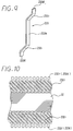
- Conductor segments 33 illustrated in Fig. 2 can be separated at the middle of U-turn portion, as shown in Fig. 9.
- Such conductor segments 233 can be used to a stator according to a third embodiment of the invention.
- conductor segment 233 is composed of straight inner portion 233h and outer portions 233i extending axially outward from opposite ends of inner portion 233h.
- Outer portions 233i incline at a certain angle to the axial direction so that end portions 233d extending from one of slots can be welded to end portions 233d extending from another slot to form a stator winding.
- Connected portions 233f are formed at both ends of the stator core and cooled by the pair of cooling fans 11, 12 (Fig. 1).
- the connected portions 233f are also formed into an edgeless raindrop shape as described before.
- the cooling fan can be axial flow fan also.
- the ball-shaped connected portions can be applied to an any kind of electric machine having water cooling structure.
- the cross-section of conductor segments 33 can be circular, elliptic or polygonal.
- a contactless arc welder other than TIG welder can be applicable to connect end portions 33d of conductor segments 33.
Abstract

Description
- The present invention relates to a stator of a vehicle alternator.
- An alternator disclosed in JP-A-3-235644 has a pair of cooling fans fixed to opposite sides of a rotor. The pair of inner cooling fans take cooling air into frames and discharge the cooling air from windows formed in the circumferential surface of the frames, thereby cooling the stator winding.
- U.S.P. 1,822,261 and WO92/06527 disclose a plurality of U-shaped conductor segments welded to form a stator winding. However, sharp edges may be formed on the welded portions. Such edges may cause concentration of mechanical stress and electrochemical stress, thereby resulting in mechanical breakdown or electrochemical corrosion. Moreover, dust or foreign particles introduced with the cooling air may accumulate on the edges if such a stator winding is cooled by such a inner cooling fans. If salt water is introduced by the inner cooling fans, insulation members disposed in the stator may be deteriorated.
- The present invention is to prevent such mechanical and electrochemical troubles on the connected portion of conductor segments forming a stator winding.
- In a stator of an alternator for a vehicle according to a main aspect of the invention, the stator winding is composed of a plurality of conductor segments having end portions extending in the opposite direction to each other and a plurality of ball-shaped connected portion between the conductor segments to form continuously connected coils. Each of the ball-shaped connected portions includes one end of one conductor segment and the other end of another conductor segment.
- Preferably, the ball-shaped connected portions are disposed at the same end of said stator core. Each of the conductor segments can have a U-shaped portion.
- The conductor segments is preferably welded by a non-contact type welder, such as a tungsten inert gas (TIG) welder, to form the connected portions into a ball shape.
- Other objects, features and characteristics of the present invention as well as the functions of related parts of the present invention will become clear from a study of the following detailed description, the appended claims and the drawings. In the drawings:
- Fig. 1 is a cross-sectional view illustrating the whole structure of a vehicle alternator having a stator according to a first embodiment of the invention;
- Fig. 2 is a perspective view of a conductor segment of the stator according to the first embodiment;
- Fig. 3 is a fragmentary schematic cross-sectional view of the stator according to the first embodiment;
- Fig. 4 is a fragmentary side view of the stator according to the first embodiment;
- Fig. 5A is a perspective view illustrating a connected portion before welding of the conductor segments illustrated in Fig. 2, Fig. 5B is a perspective view of the connected portion after welding, and Fig. 5C is a schematic cross-sectional view of the connected portion;
- Fig. 6 is a perspective view illustrating coil ends of the stator according to the first embodiment;
- Fig. 7 is a fragmentary cross-sectional view of the stator according to a second embodiment of the invention;
- Fig. 8 is a fragmentary perspective view of the stator according to the second embodiment;
- Fig. 9 is a perspective view of a conductor segment of a stator according to a third embodiment of the invention; and
- Fig. 10 is a fragmentary side view of the stator according to the third embodiment.
-
- A stator of a vehicle alternator according to a first embodiment of the invention is described with reference to Figs. 1- 6.
- In Fig. 1, vehicle alternator 1 is composed of
stator 2,rotor 3, a pair offrames 4, rectifier 5 and others. -
Stator 2 is composed ofstator core 32, a plurality ofconductor segments 33 forming a stator winding andinsulator 34 disposed betweenstator core 32 and theconductor segments 33.Stator core 32 is a laminate of cylindrical thin steel sheets which has a plurality of slots in the inner periphery thereof.Conductor segments 33 extend fromstator core 32 to formcoil ends 31. -
Rotor 3 is composed of cylindrically-wound-and-insulated field coil 8, a pair of pole cores 7 respectively having six claw poles which enclose field coil therebetween and shaft 6 press-fitted to the pair of cores 7.Rotor 3 has a mixed flowtype cooling fan 11 at the front end thereof to supply cooling air from front portions of the rotor in the axial and radial directions and a centrifugaltype cooling fan 12 at the rear end thereof to supply cooling air from rear portions of the rotor in the radial direction. - The pair of
frames 4 accommodates and supportsstator 2 androtor 3 so thatrotor 3 can rotate about shaft 6 andstator core 2 can be disposed around circumference ofrotor 3 at a certain air gap. The pair offrames 4 has air-discharge windows 42 at the portions thereof opposite tocoil ends 31 ofstator 2 and air-intake windows 41 at the axially opposite surfaces thereof. - Vehicle alternator 1 is driven to rotate by an engine (not shown) via
pulley 20 and a belt. When field coil 8 is supplied with exciting current, the claw poles of the pair of pole cores 7 are excited to generate three-phase ac voltage in the stator winding, and dc power is supplied from output terminals of rectifier 5. - As shown in Fig. 2, each of U-shaped
copper conductor segments 33 hasU-turn portion 33c, inner-portion 33a to be disposed in one ofslots 35 at a circumference insideU-turn portion 33c and outer-portion 33b to be disposed in another ofslots 35 at a circumference outsideU-turn portion 33c. Each of inner-portion 33a and outer-portion 33b has a straight portion to be disposed in one ofslots 35 and a portion to extend outward from the one ofslots 35. - When the stator winding is formed, two
conductor segments 33 are inserted in every one ofslots 35 and eachend portion 33d is connected withdifferent end portion 33d extending from different one ofslots 35. As shown in Fig. 3, both inner-portion 33a and outer-portion 33b have a rectangular cross-section with the radial sides being longer than the circumferential sides. Becauseconductor segments 33 are not coated with insulating material, S-shaped insulator 34 is disposed in each ofslots 35 to insulate two conductor segments from each other. - As shown in Fig. 4,
U-turn portions 33c are disposed at the same end ofstator core 32. Inclinedportions 33e extending left are formed from outer-portion 33b, andinclined portions 33e extending right are formed from inner-portion 33a to formuniform coil ends 31. Each of connectedportions 33f is formed to join another as shown in Fig. 5A. - Joining
end portions 33d are welded together by a contactless type welder such as a tungsten inert-gas welder (hereinafter referred to as the TIG welder) so that only limited area of end portions can be melted to form ball-shaped or raindrop-shaped connectedportions 33f. The TIG welder discharges arc current between a tungsten electrode and a base metal member in an inert gas to melt the base metal member and a filler metal member for welding. The TIG welder can control quantity of heat and quantity of filler material separately. -
End portions 33d of neighboringconductor segments 33 are put side by side, and a nozzle having a tungsten electrode is brought near theend portions 33d to be welded by the TIG welder. - Because
conductor segments 33 made of copper is highly heat conductive, each of connectedportions 33f is melted wide enough to form into a raindrop-shaped ball without any edge due to surface tension as shown in Fig. 5B. Each of connectedportions 33f becomes larger thanconductor segment 33 both in thickness (T > t) and in width (W > 2w). Thus, sufficient mechanical strength and electrical connection can be provided at the connectedportions 33f. The edge-less ball-shaped portions are free from concentration of stresses and corrosion. The ball-shaped surface of the connectedportion 33f is coated evenly with resinous film 33g for protection and insulation as shown in Fig. 5C. - The stator winding is formed as follows.
U-shaped conductor segments 33 are inserted intorespective slots 35 ofstator 2 so thatU-turn portions 33c are disposed on the same axial end ofstator core 32, so that outer-portions 33b are disposed at the inner portion of slots 35 (or an outer circumference of stator core 32), and inner-portion 33a are disposed in the outlet portion of slots 35 (or an inner circumference of stator core 32) as shown in Fig. 3. - Each of
conductor segments 33 is manufactured as follows. A copper plate is bent and press-formed into a U-shape so that opposite sides of outer-portion 33b and inner-portion 33a are inserted in one ofslots 35 to be in contact with the parallel side walls of one ofslots 33 viainsulator 34. - As shown in Fig. 6, each of two
end portions 33d of one ofconductor segments 33 is bent in the circumferential direction opposite to each other so that outer-portion 33b of the one ofconductor segments 33 can be connected to inner-portion 33a of another of conductor segments extending from different one ofslots 35 and inner-portion 33a of the former can be connected to outer-portion 33b of another ofconductor segments 33 extending from different one ofslots 35 atend portions 33d, thereby forming a ring ofconnected portions 33f, at a certain height fromstator core 32. Then, connectedportions 33f is dipped in a tank of liquid insulation material, and taken out from the tank to form uniform insulation film onconnected portions 33f. - Because all
end portions 33d are disposed on the same end ofstator core 32, the connection can be carried out by a TIG welder without turningstator core 32. Because allconductor segments 33 are almost the same in shape andconnected portions 33f are located at the same height, the dipping process for the insulation of allconnected portions 33f can be carried out at the same time. Thus, the insulation process can be made simple, and production cost can be reduced. - The number of conductor members per slot can be increased to more than two. As shown in Fig. 7, a stator according to a second embodiment of the invention has four
conductor segments 133 aligned in the radial direction in one ofslot 135.Conductor segments 133 have insulation coating thereon, and ainsulator 134 is disposed betweenconductor segments 133 and inner wall ofslot 135. The connected portions are shown in Fig. 8. Fourconductor segments 133 in one ofslots 135 extends alternately in the opposite circumferential directions. That is, the outermost segments extend clockwise, and the innermost segments extend counter-clockwise in Fig. 8. End portions 133d ofconductor segments 133 extending from one ofslots 135 are respectively connected to end portions 133d extending from different one ofslots 135 spaced apart at a certain pitch therefrom. In other words, theinnermost conductor segments 133 are connected respectively to the secondinner conductor segments 133, and thirdinner conductor segments 133 are connected respectively to theoutermost conductor segments 133. Accordingly, a plurality of connected portions 133f are formed into two rings so that each of connected portions 133f is spaced apart from another in both radial and circumferential directions. All the connected portions 133f are welded by a TIG welder to have edgeless raindrop shape in the manner substantially the same as the stator according to the first embodiment. - The above structure is effective to provide a smaller-sized vehicle alternator having the same number of
slots 35, the distance between the connected portions is closer. -
Conductor segments 33 illustrated in Fig. 2 can be separated at the middle of U-turn portion, as shown in Fig. 9.Such conductor segments 233 can be used to a stator according to a third embodiment of the invention. In Fig. 9,conductor segment 233 is composed of straightinner portion 233h andouter portions 233i extending axially outward from opposite ends ofinner portion 233h.Outer portions 233i incline at a certain angle to the axial direction so thatend portions 233d extending from one of slots can be welded to endportions 233d extending from another slot to form a stator winding.Connected portions 233f are formed at both ends of the stator core and cooled by the pair of coolingfans 11, 12 (Fig. 1). Theconnected portions 233f are also formed into an edgeless raindrop shape as described before. - It is also possible to provide a single centrifugal cooling fan to cool
connected portions 33f instead of a pair of cooling fans. The cooling fan can be axial flow fan also. The ball-shaped connected portions can be applied to an any kind of electric machine having water cooling structure. The cross-section ofconductor segments 33 can be circular, elliptic or polygonal. A contactless arc welder other than TIG welder can be applicable to connectend portions 33d ofconductor segments 33. - In the foregoing description of the present invention, the invention has been disclosed with reference to specific embodiments thereof. It will, however, be evident that various modifications and changes may be made to the specific embodiments of the present invention without departing from the broader spirit and scope of the invention as set forth in the appended claims. Accordingly, the description of the present invention in this document is to be regarded in an illustrative, rather than restrictive, sense.
Claims (13)
- A stator (2) of an alternator (1) for a vehicle including a stator core (32) having a plurality of slots (35) and stator windings (33) disposed in said plurality of slots (35), whereinsaid stator winding (33) comprises a plurality of conductor segments (33) having a first and second ends (33d) and a plurality of ball-shaped connected portion (33f) between said conductor segments (33) thereby forming continuously connected coils, andeach of said ball-shaped connected portions (33f) comprises said first end (33d) of one of said conductor segments (33) and said second end (33d) of another of said conductor segments (33).
- The stator (2) as claimed in claim 1, whereinsaid ball-shaped connected portions (33f) are disposed at the same end of said stator core (32).
- The stator as claimed in claim 2, whereineach of said conductor segments (33) has a U-shaped portion (33c).
- The stator (2) as claimed claim 1, whereineach of said connected portions (33f) is disposed to receive cooling air from the inside of said stator (2).
- The stator (2) as claimed in claim 1, whereineach of said conductor segments (33) is welded by a non-contact type welder.
- The stator (2) as claimed in claim 5, whereinsaid non-contact type welder is a TIG welder.
- The stator (2) as claimed in claim 1, whereinevery two of said conductor segments (33) are disposed in one of said slots (35).
- The stator (2) as claimed in claim 1, whereinsaid ball-shaped connected portions (33f) are disposed at the same height from said stator core (32).
- The stator (2) as claimed in claim 1, whereineach of said conductor segments has rectangular cross section at said first and second ends,said rectangular cross section has radial sides longer than circumferential sides, andsaid first end of one of said conductor segments and said second end of another of said conductor segments are disposed side by side.
- The stator (2) as claimed in claim 9, whereineach of said connected portions (33f) is larger in both thickness and width than any one of said first and second ends (33d) of said conductor segments (33).
- The stator (2) as claimed in claim 10, whereineach of said connected portion (33f) has a shape that has radial size longer than circumferential size.
- The stator (2) as claimed in claim 11, whereinsaid connected portions (33f) are disposed in a circumferential line.
- The stator (2) as claimed in claim 11, whereinsaid connected portions (33f) are disposed in a plurality of circumferential lines.
Priority Applications (1)
| Application Number | Priority Date | Filing Date | Title |
|---|---|---|---|
| DE69803745T DE69803745T3 (en) | 1997-12-10 | 1998-12-04 | Alternator for motor vehicles |
Applications Claiming Priority (8)
| Application Number | Priority Date | Filing Date | Title |
|---|---|---|---|
| JP36206397 | 1997-12-10 | ||
| JP36206397 | 1997-12-10 | ||
| JP12834198A JP3855453B2 (en) | 1997-05-26 | 1998-04-21 | AC generator for vehicles |
| JP12834198 | 1998-04-21 | ||
| JP12477698A JP3456144B2 (en) | 1997-05-26 | 1998-05-07 | Rotating electric machine |
| JP12477698 | 1998-05-07 | ||
| JP14300998A JP3724951B2 (en) | 1998-05-25 | 1998-05-25 | Vehicle alternator |
| JP14300998 | 1998-05-25 |
Publications (4)
| Publication Number | Publication Date |
|---|---|
| EP0923187A2 true EP0923187A2 (en) | 1999-06-16 |
| EP0923187A3 EP0923187A3 (en) | 1999-10-20 |
| EP0923187B1 EP0923187B1 (en) | 2002-02-06 |
| EP0923187B2 EP0923187B2 (en) | 2012-08-15 |
Family
ID=27471063
Family Applications (1)
| Application Number | Title | Priority Date | Filing Date |
|---|---|---|---|
| EP98123192A Expired - Lifetime EP0923187B2 (en) | 1997-12-10 | 1998-12-04 | Alternator for a vehicle |
Country Status (2)
| Country | Link |
|---|---|
| EP (1) | EP0923187B2 (en) |
| DE (1) | DE69803745T3 (en) |
Cited By (5)
| Publication number | Priority date | Publication date | Assignee | Title |
|---|---|---|---|---|
| EP1081830A2 (en) * | 1999-08-06 | 2001-03-07 | Denso Corporation | Electric rotary machine having a plurality of conductor segments and method of manufacturing the same |
| EP1126579A1 (en) * | 2000-02-14 | 2001-08-22 | Mitsubishi Denki Kabushiki Kaisha | Stator of alternating current generator |
| EP1128527A1 (en) * | 2000-02-24 | 2001-08-29 | Mitsubishi Denki Kabushiki Kaisha | Alternator |
| EP1134877A2 (en) * | 2000-03-16 | 2001-09-19 | Mitsubishi Denki Kabushiki Kaisha | Stator for an automotive alternator and method of manufacturing the same |
| CN109309423A (en) * | 2017-07-28 | 2019-02-05 | 天津市松正电动汽车技术股份有限公司 | A kind of flat wire motor stator winding structure |
Families Citing this family (3)
| Publication number | Priority date | Publication date | Assignee | Title |
|---|---|---|---|---|
| US8789259B2 (en) | 2011-11-17 | 2014-07-29 | Remy Technologies, L.L.C. | Method of winding a stator core with a continuous conductor having a rectangular cross-section and a stator core |
| US9467010B2 (en) | 2011-11-17 | 2016-10-11 | Remy Technologies, L.L.C. | Method of winding a stator core with a continuous conductor having a rectangular cross-section and a stator core |
| US8745847B2 (en) * | 2011-11-17 | 2014-06-10 | Remy Technologies, L.L.C. | Method of P-forming a continuous conductor having a rectangular cross section and a stator including a stator winding formed from a P-formed conductor having a rectangular cross-section |
Citations (23)
| Publication number | Priority date | Publication date | Assignee | Title |
|---|---|---|---|---|
| US1332154A (en) † | 1918-12-23 | 1920-02-24 | Vincent G Apple | Machine for bending armature-terminals |
| US1556891A (en) † | 1923-11-20 | 1925-10-13 | Dayton Enginering Lab Company | Apparatus for making armatures |
| US1822261A (en) * | 1927-06-28 | 1931-09-08 | Vincent G Apple | Bar wound field element |
| US1826295A (en) † | 1928-06-14 | 1931-10-06 | Vincent G Apple | Dynamo electric machine element |
| US2407935A (en) † | 1944-05-25 | 1946-09-17 | Chrysler Corp | Electrical machine |
| FR1140338A (en) † | 1956-01-20 | 1957-07-19 | Laborde & Kupfer | Device for mounting the stator winding elements of alternators or others |
| US2928963A (en) † | 1956-06-06 | 1960-03-15 | Gen Motors Corp | Dynamoelectric machine |
| DE1180045B (en) † | 1961-07-11 | 1964-10-22 | Bbc Brown Boveri & Cie | Process for the production and isolation of soldered connections on the end connections of the stator windings of large AC machines |
| JPS573540A (en) † | 1980-06-09 | 1982-01-09 | Fuji Electric Co Ltd | Coil of electric rotary machine |
| US4418295A (en) † | 1979-10-09 | 1983-11-29 | Nippondenso Co., Ltd. | Multi-path cooling in AC generator for vehicle |
| US4419597A (en) † | 1980-05-09 | 1983-12-06 | Nippondenso Co., Ltd. | Alternator assembly having a rectifier device in thermal contact with case and cover |
| DE3441825A1 (en) † | 1984-08-27 | 1986-05-22 | Siemens AG, 1000 Berlin und 8000 München | Three-phase or multi-phase bar wave winding for an electrical machine having p pole pairs and N slots |
| FR2594271A1 (en) † | 1986-02-13 | 1987-08-14 | Paris & Du Rhone | Rotor for electric rotating machine, with slots housing two overlying conductors |
| SU1377964A1 (en) † | 1986-05-11 | 1988-02-28 | Ленинградское Электромашиностроительное Объединение "Электросила" Им.С.М.Кирова | Combination single=phase/m2-phase/m2-phase electric machine winding |
| JPS63274335A (en) † | 1987-04-30 | 1988-11-11 | Nippon Denso Co Ltd | Armature coil |
| JPH03235644A (en) † | 1990-02-07 | 1991-10-21 | Hitachi Ltd | Ac generator for vehicle |
| EP0454039A1 (en) † | 1990-04-24 | 1991-10-30 | Nippondenso Co., Ltd. | Alternating current generator having a plurality of independent three-phase windings |
| US5097167A (en) † | 1985-03-27 | 1992-03-17 | Nippondenso Co., Ltd. | Rotary electric machine coil assemblies |
| WO1992006527A1 (en) * | 1990-10-04 | 1992-04-16 | Robert Bosch Gmbh | Stator for electric motors and process for making it |
| US5210928A (en) * | 1990-08-15 | 1993-05-18 | Hitachi, Ltd. | Method of manufacturing an electric motor |
| DE4343025A1 (en) † | 1992-12-21 | 1994-06-23 | Hitachi Ltd | Rotor armature and method for forming an armature winding |
| EP0730335A2 (en) † | 1993-10-15 | 1996-09-04 | Nippondenso Co., Ltd. | Electric rotating machine |
| JPH09215280A (en) † | 1996-01-31 | 1997-08-15 | Denso Corp | Armature coil jointing method |
-
1998
- 1998-12-04 EP EP98123192A patent/EP0923187B2/en not_active Expired - Lifetime
- 1998-12-04 DE DE69803745T patent/DE69803745T3/en not_active Expired - Lifetime
Patent Citations (23)
| Publication number | Priority date | Publication date | Assignee | Title |
|---|---|---|---|---|
| US1332154A (en) † | 1918-12-23 | 1920-02-24 | Vincent G Apple | Machine for bending armature-terminals |
| US1556891A (en) † | 1923-11-20 | 1925-10-13 | Dayton Enginering Lab Company | Apparatus for making armatures |
| US1822261A (en) * | 1927-06-28 | 1931-09-08 | Vincent G Apple | Bar wound field element |
| US1826295A (en) † | 1928-06-14 | 1931-10-06 | Vincent G Apple | Dynamo electric machine element |
| US2407935A (en) † | 1944-05-25 | 1946-09-17 | Chrysler Corp | Electrical machine |
| FR1140338A (en) † | 1956-01-20 | 1957-07-19 | Laborde & Kupfer | Device for mounting the stator winding elements of alternators or others |
| US2928963A (en) † | 1956-06-06 | 1960-03-15 | Gen Motors Corp | Dynamoelectric machine |
| DE1180045B (en) † | 1961-07-11 | 1964-10-22 | Bbc Brown Boveri & Cie | Process for the production and isolation of soldered connections on the end connections of the stator windings of large AC machines |
| US4418295A (en) † | 1979-10-09 | 1983-11-29 | Nippondenso Co., Ltd. | Multi-path cooling in AC generator for vehicle |
| US4419597A (en) † | 1980-05-09 | 1983-12-06 | Nippondenso Co., Ltd. | Alternator assembly having a rectifier device in thermal contact with case and cover |
| JPS573540A (en) † | 1980-06-09 | 1982-01-09 | Fuji Electric Co Ltd | Coil of electric rotary machine |
| DE3441825A1 (en) † | 1984-08-27 | 1986-05-22 | Siemens AG, 1000 Berlin und 8000 München | Three-phase or multi-phase bar wave winding for an electrical machine having p pole pairs and N slots |
| US5097167A (en) † | 1985-03-27 | 1992-03-17 | Nippondenso Co., Ltd. | Rotary electric machine coil assemblies |
| FR2594271A1 (en) † | 1986-02-13 | 1987-08-14 | Paris & Du Rhone | Rotor for electric rotating machine, with slots housing two overlying conductors |
| SU1377964A1 (en) † | 1986-05-11 | 1988-02-28 | Ленинградское Электромашиностроительное Объединение "Электросила" Им.С.М.Кирова | Combination single=phase/m2-phase/m2-phase electric machine winding |
| JPS63274335A (en) † | 1987-04-30 | 1988-11-11 | Nippon Denso Co Ltd | Armature coil |
| JPH03235644A (en) † | 1990-02-07 | 1991-10-21 | Hitachi Ltd | Ac generator for vehicle |
| EP0454039A1 (en) † | 1990-04-24 | 1991-10-30 | Nippondenso Co., Ltd. | Alternating current generator having a plurality of independent three-phase windings |
| US5210928A (en) * | 1990-08-15 | 1993-05-18 | Hitachi, Ltd. | Method of manufacturing an electric motor |
| WO1992006527A1 (en) * | 1990-10-04 | 1992-04-16 | Robert Bosch Gmbh | Stator for electric motors and process for making it |
| DE4343025A1 (en) † | 1992-12-21 | 1994-06-23 | Hitachi Ltd | Rotor armature and method for forming an armature winding |
| EP0730335A2 (en) † | 1993-10-15 | 1996-09-04 | Nippondenso Co., Ltd. | Electric rotating machine |
| JPH09215280A (en) † | 1996-01-31 | 1997-08-15 | Denso Corp | Armature coil jointing method |
Non-Patent Citations (17)
| Title |
|---|
| BIBLIOTHÈQUE DE L'ENSEIGNEMENT TECHNIQUE: 'Électrotechnique à l'usage des ingénieurs', 1952, DUNOD, PARIS article A. FOUILLÉ, pages 114 - 120 † |
| BOSCH: 'Automotive electric/electronic Systems', vol. 2, June 1994, ROBERT BOSCH GMBH, STUTTGART, ISBN 1-56091-596-X † |
| BÜRGER, SCHIMANN COMPACT LIQUID COOLED ATERNATOR 20 October 1997 - 22 October 1997, AACHEN, † |
| DENSO - HISTORY OF DENSO 1996 - 1996, † |
| DIAGNOSTIC DES PANNES: 'Circuit de charge', 1995, E.T.A.I, PARIS, ISBN 2-7268-8160-2 article G. DUMAZEAU, D. RODES: 'tests, contrÔles, Diagnostic localisation de la panne' † |
| E.T.A.I REVUE TECHNIQUE AUTOMOBILE NR. 572 April 1995 - April 1995, PARIS, pages 73 - 74 † |
| E.T.A.I REVUE TECHNIQUE AUTOMOBILE NR. 579 December 1995 - December 1995, PARIS, pages 58 - 59 † |
| 'Engine Electrical' DENSO 1996 - 1996, † |
| M. BLANC LE SOUDAGE TIG 23 November 1972 - 23 November 1972, pages 146 - 150 † |
| M. BLANC LE SOUDAGE TIG DES LAMES DE COLLECTEURS 23 November 1972 - 23 November 1972, pages 176 - 177 † |
| NIPPONDENSO CO, LTD. 1986 - 1986, † |
| ROBERT BOSCH GMBH BOSCH NOTICE TECHNIQUE- DÉMARREURS ÉLECTRIQUE vol. 1, 01 October 1972 - 01 October 1972, ALLEMAGNE, page Q † |
| ROBERT BOSCH GMBH BOSCH NOTICE TECHNIQUE GÉNÉRATRICES vol. 1, 01 November 1972 - 01 November 1972, ALLEMAGNE, † |
| ROBERT BOSCH GMBH TEILE FÜR STARTER UND GENERATOREN 1994 - 1994, ALLEMAGNE, † |
| 'Système de génération éléctrique' VALEO June 1990 - June 1990, † |
| THÉORIE, FONCTIONNEMENT ET CALCUL DES MACHINES ÉLECTRIQUES- 2: 'Machines synchrones', 1965, DUNOD, PARIS article A. GUILBERT † |
| VALEO TEAM: ' V40 ESA Alterateur' BROCHURE TECHNIQUE VALEO TEAM GARAGE July 1993 - July 1993, † |
Cited By (11)
| Publication number | Priority date | Publication date | Assignee | Title |
|---|---|---|---|---|
| EP1081830A2 (en) * | 1999-08-06 | 2001-03-07 | Denso Corporation | Electric rotary machine having a plurality of conductor segments and method of manufacturing the same |
| EP1081830A3 (en) * | 1999-08-06 | 2001-09-12 | Denso Corporation | Electric rotary machine having a plurality of conductor segments and method of manufacturing the same |
| US6459177B1 (en) | 1999-08-06 | 2002-10-01 | Denso Corporation | Electric rotary machine having a plurality of conductor segments and method of manufacturing the same |
| EP1126579A1 (en) * | 2000-02-14 | 2001-08-22 | Mitsubishi Denki Kabushiki Kaisha | Stator of alternating current generator |
| US6288462B1 (en) | 2000-02-14 | 2001-09-11 | Mitsubishi Denki Kabushiki Kaisha | Stator of alternating current generator |
| EP1128527A1 (en) * | 2000-02-24 | 2001-08-29 | Mitsubishi Denki Kabushiki Kaisha | Alternator |
| US6448681B1 (en) | 2000-02-24 | 2002-09-10 | Mitsubishi Denki Kabushiki Kaisha | Alternator |
| EP1134877A2 (en) * | 2000-03-16 | 2001-09-19 | Mitsubishi Denki Kabushiki Kaisha | Stator for an automotive alternator and method of manufacturing the same |
| EP1134877A3 (en) * | 2000-03-16 | 2004-01-14 | Mitsubishi Denki Kabushiki Kaisha | Stator for an automotive alternator and method of manufacturing the same |
| US6946759B2 (en) | 2000-03-16 | 2005-09-20 | Mitsubishi Denki Kabushiki Kaisha | Stator for an automotive alternator and method of manufacturing the same |
| CN109309423A (en) * | 2017-07-28 | 2019-02-05 | 天津市松正电动汽车技术股份有限公司 | A kind of flat wire motor stator winding structure |
Also Published As
| Publication number | Publication date |
|---|---|
| DE69803745D1 (en) | 2002-03-21 |
| EP0923187B1 (en) | 2002-02-06 |
| EP0923187A3 (en) | 1999-10-20 |
| DE69803745T3 (en) | 2012-12-06 |
| EP0923187B2 (en) | 2012-08-15 |
| DE69803745T2 (en) | 2002-09-26 |
Similar Documents
| Publication | Publication Date | Title |
|---|---|---|
| US6181043B1 (en) | Alternator for vehicle | |
| US6335583B1 (en) | Stator of vehicle AC generator and method of manufacturing the same | |
| US6462453B1 (en) | Stator for an alternator | |
| US6604272B1 (en) | Method of manufacturing a vehicle AC generator | |
| US6208060B1 (en) | Stator of vehicle AC generator and method of manufacturing the same | |
| US8884488B2 (en) | Stator for electric rotating machine and manufacturing method of the same | |
| JP3275839B2 (en) | AC generator for vehicles | |
| EP0961386B1 (en) | Stator of ac generator for vehicle | |
| US6834422B2 (en) | Method of forming stator winding of rotary electric machine | |
| US6998749B2 (en) | Rotary electric machine | |
| US8344573B2 (en) | Stator for use in electric rotating machine | |
| US6252326B1 (en) | Stator of vehicle AC generator with circumferentially offset coil ends | |
| EP1204195B1 (en) | Stator arrangement of rotary electric machine | |
| US20070007843A1 (en) | Rotary electric machine for vehicles | |
| JP2004015839A (en) | Method of manufacturing stator winding of rotary electric machine, winding structure, and method of manufacturing winding | |
| US8772995B2 (en) | Stator for electric rotating machine | |
| US20080054750A1 (en) | Rotary electric machine and stator for rotary electric machines | |
| US20030067239A1 (en) | Stator arrangement of vehicle AC generator | |
| JP3630141B2 (en) | Manufacturing method of stator of rotating electric machine | |
| KR100398761B1 (en) | Alternator | |
| EP0923187B1 (en) | Alternator for a vehicle | |
| JP3724951B2 (en) | Vehicle alternator | |
| JP3738772B2 (en) | AC generator for vehicles | |
| JP4120122B2 (en) | AC generator for vehicles | |
| JP2002204543A (en) | Rotating electric machine for vehicle |
Legal Events
| Date | Code | Title | Description |
|---|---|---|---|
| PUAI | Public reference made under article 153(3) epc to a published international application that has entered the european phase |
Free format text: ORIGINAL CODE: 0009012 |
|
| AK | Designated contracting states |
Kind code of ref document: A2 Designated state(s): DE FR GB IT |
|
| AX | Request for extension of the european patent |
Free format text: AL;LT;LV;MK;RO;SI |
|
| PUAL | Search report despatched |
Free format text: ORIGINAL CODE: 0009013 |
|
| AK | Designated contracting states |
Kind code of ref document: A3 Designated state(s): AT BE CH CY DE DK ES FI FR GB GR IE IT LI LU MC NL PT SE |
|
| AX | Request for extension of the european patent |
Free format text: AL;LT;LV;MK;RO;SI |
|
| RIC1 | Information provided on ipc code assigned before grant |
Free format text: 6H 02K 3/12 A, 6H 02K 15/00 B |
|
| 17P | Request for examination filed |
Effective date: 19991206 |
|
| AKX | Designation fees paid |
Free format text: DE FR GB IT |
|
| GRAG | Despatch of communication of intention to grant |
Free format text: ORIGINAL CODE: EPIDOS AGRA |
|
| 17Q | First examination report despatched |
Effective date: 20010806 |
|
| GRAG | Despatch of communication of intention to grant |
Free format text: ORIGINAL CODE: EPIDOS AGRA |
|
| GRAH | Despatch of communication of intention to grant a patent |
Free format text: ORIGINAL CODE: EPIDOS IGRA |
|
| GRAA | (expected) grant |
Free format text: ORIGINAL CODE: 0009210 |
|
| REG | Reference to a national code |
Ref country code: GB Ref legal event code: IF02 |
|
| AK | Designated contracting states |
Kind code of ref document: B1 Designated state(s): DE FR GB IT |
|
| REF | Corresponds to: |
Ref document number: 69803745 Country of ref document: DE Date of ref document: 20020321 |
|
| PLBQ | Unpublished change to opponent data |
Free format text: ORIGINAL CODE: EPIDOS OPPO |
|
| PLBI | Opposition filed |
Free format text: ORIGINAL CODE: 0009260 |
|
| PLBF | Reply of patent proprietor to notice(s) of opposition |
Free format text: ORIGINAL CODE: EPIDOS OBSO |
|
| 26 | Opposition filed |
Opponent name: KOCH, ALEXANDER W. DR.-ING. Effective date: 20021105 Opponent name: VALEO EQUIPEMENTS ELECTRIQUES MOTEUR Effective date: 20021105 |
|
| PLBF | Reply of patent proprietor to notice(s) of opposition |
Free format text: ORIGINAL CODE: EPIDOS OBSO |
|
| PLBB | Reply of patent proprietor to notice(s) of opposition received |
Free format text: ORIGINAL CODE: EPIDOSNOBS3 |
|
| APBP | Date of receipt of notice of appeal recorded |
Free format text: ORIGINAL CODE: EPIDOSNNOA2O |
|
| APAH | Appeal reference modified |
Free format text: ORIGINAL CODE: EPIDOSCREFNO |
|
| APBP | Date of receipt of notice of appeal recorded |
Free format text: ORIGINAL CODE: EPIDOSNNOA2O |
|
| APAW | Appeal reference deleted |
Free format text: ORIGINAL CODE: EPIDOSDREFNO |
|
| APBQ | Date of receipt of statement of grounds of appeal recorded |
Free format text: ORIGINAL CODE: EPIDOSNNOA3O |
|
| APBQ | Date of receipt of statement of grounds of appeal recorded |
Free format text: ORIGINAL CODE: EPIDOSNNOA3O |
|
| APBU | Appeal procedure closed |
Free format text: ORIGINAL CODE: EPIDOSNNOA9O |
|
| PUAH | Patent maintained in amended form |
Free format text: ORIGINAL CODE: 0009272 |
|
| STAA | Information on the status of an ep patent application or granted ep patent |
Free format text: STATUS: PATENT MAINTAINED AS AMENDED |
|
| 27A | Patent maintained in amended form |
Effective date: 20120815 |
|
| AK | Designated contracting states |
Kind code of ref document: B2 Designated state(s): DE FR GB IT |
|
| REG | Reference to a national code |
Ref country code: DE Ref legal event code: R102 Ref document number: 69803745 Country of ref document: DE Effective date: 20120815 |
|
| REG | Reference to a national code |
Ref country code: FR Ref legal event code: PLFP Year of fee payment: 18 |
|
| REG | Reference to a national code |
Ref country code: FR Ref legal event code: PLFP Year of fee payment: 19 |
|
| REG | Reference to a national code |
Ref country code: FR Ref legal event code: PLFP Year of fee payment: 20 |
|
| PGFP | Annual fee paid to national office [announced via postgrant information from national office to epo] |
Ref country code: DE Payment date: 20171211 Year of fee payment: 20 Ref country code: FR Payment date: 20171221 Year of fee payment: 20 |
|
| PGFP | Annual fee paid to national office [announced via postgrant information from national office to epo] |
Ref country code: GB Payment date: 20171221 Year of fee payment: 20 |
|
| PGFP | Annual fee paid to national office [announced via postgrant information from national office to epo] |
Ref country code: IT Payment date: 20171221 Year of fee payment: 20 |
|
| REG | Reference to a national code |
Ref country code: DE Ref legal event code: R071 Ref document number: 69803745 Country of ref document: DE |
|
| REG | Reference to a national code |
Ref country code: GB Ref legal event code: PE20 Expiry date: 20181203 |
|
| PG25 | Lapsed in a contracting state [announced via postgrant information from national office to epo] |
Ref country code: GB Free format text: LAPSE BECAUSE OF EXPIRATION OF PROTECTION Effective date: 20181203 |