EP0924793B1 - Radio communications handset antenna arrangements - Google Patents
Radio communications handset antenna arrangements Download PDFInfo
- Publication number
- EP0924793B1 EP0924793B1 EP98203306A EP98203306A EP0924793B1 EP 0924793 B1 EP0924793 B1 EP 0924793B1 EP 98203306 A EP98203306 A EP 98203306A EP 98203306 A EP98203306 A EP 98203306A EP 0924793 B1 EP0924793 B1 EP 0924793B1
- Authority
- EP
- European Patent Office
- Prior art keywords
- antenna
- radiating element
- radio communications
- ground plane
- communications handset
- Prior art date
- Legal status (The legal status is an assumption and is not a legal conclusion. Google has not performed a legal analysis and makes no representation as to the accuracy of the status listed.)
- Expired - Lifetime
Links
- 238000004891 communication Methods 0.000 title claims description 14
- 230000005404 monopole Effects 0.000 claims description 11
- 230000009977 dual effect Effects 0.000 description 8
- KTXUOWUHFLBZPW-UHFFFAOYSA-N 1-chloro-3-(3-chlorophenyl)benzene Chemical compound ClC1=CC=CC(C=2C=C(Cl)C=CC=2)=C1 KTXUOWUHFLBZPW-UHFFFAOYSA-N 0.000 description 6
- 238000003780 insertion Methods 0.000 description 4
- 230000037431 insertion Effects 0.000 description 4
- 230000005855 radiation Effects 0.000 description 4
- 230000001939 inductive effect Effects 0.000 description 3
- 239000003990 capacitor Substances 0.000 description 2
- 230000001419 dependent effect Effects 0.000 description 2
- 230000002708 enhancing effect Effects 0.000 description 2
- 238000004519 manufacturing process Methods 0.000 description 2
- 238000010295 mobile communication Methods 0.000 description 2
- 238000000926 separation method Methods 0.000 description 2
- 238000001228 spectrum Methods 0.000 description 2
- 230000005540 biological transmission Effects 0.000 description 1
- 230000015572 biosynthetic process Effects 0.000 description 1
- 239000004020 conductor Substances 0.000 description 1
- 238000010276 construction Methods 0.000 description 1
- 230000008878 coupling Effects 0.000 description 1
- 230000001808 coupling effect Effects 0.000 description 1
- 238000010168 coupling process Methods 0.000 description 1
- 238000005859 coupling reaction Methods 0.000 description 1
- 230000001627 detrimental effect Effects 0.000 description 1
- 231100001261 hazardous Toxicity 0.000 description 1
- 230000002093 peripheral effect Effects 0.000 description 1
Images


Classifications
-
- H—ELECTRICITY
- H01—ELECTRIC ELEMENTS
- H01Q—ANTENNAS, i.e. RADIO AERIALS
- H01Q1/00—Details of, or arrangements associated with, antennas
- H01Q1/12—Supports; Mounting means
- H01Q1/22—Supports; Mounting means by structural association with other equipment or articles
- H01Q1/24—Supports; Mounting means by structural association with other equipment or articles with receiving set
- H01Q1/241—Supports; Mounting means by structural association with other equipment or articles with receiving set used in mobile communications, e.g. GSM
- H01Q1/242—Supports; Mounting means by structural association with other equipment or articles with receiving set used in mobile communications, e.g. GSM specially adapted for hand-held use
- H01Q1/243—Supports; Mounting means by structural association with other equipment or articles with receiving set used in mobile communications, e.g. GSM specially adapted for hand-held use with built-in antennas
-
- H—ELECTRICITY
- H04—ELECTRIC COMMUNICATION TECHNIQUE
- H04R—LOUDSPEAKERS, MICROPHONES, GRAMOPHONE PICK-UPS OR LIKE ACOUSTIC ELECTROMECHANICAL TRANSDUCERS; DEAF-AID SETS; PUBLIC ADDRESS SYSTEMS
- H04R1/00—Details of transducers, loudspeakers or microphones
- H04R1/20—Arrangements for obtaining desired frequency or directional characteristics
- H04R1/22—Arrangements for obtaining desired frequency or directional characteristics for obtaining desired frequency characteristic only
- H04R1/225—Arrangements for obtaining desired frequency or directional characteristics for obtaining desired frequency characteristic only for telephonic receivers
Definitions
- the invention generally relates to radio communications handsets, and in particular to internal antenna arrangements.
- Half or quarter wavelength monopoles extend a significant length from the handset and have a number of disadvantages including the inconvenience of such a long protuberance which is easily broken and can be hazardous to users eyes for example.
- the inverted L antenna requires a significant physical length (quarter wavelength) for efficient operation, this is generally not possible within a handset so that a shortened L is generally inefficient.
- US4021810 discloses a 3D array of meander structure conductors above a ground plane which is complex to produce and is susceptible to the vagaries of manufacturing tolerances.
- WO96/38882 discloses a printed meandering monopole antenna extending from a mobile handset. While the meandering monopole is shorter than a standard monopole, it still represents an inconvenient protuberance outside the handset.
- WO93/12559 discloses a planar metallic sheet inverted F antenna having dependant elements angled with respect to the planar structure. As such it is delicate and complicated to manufacture.
- US-A-4 679 233 discloses a radio communications handset comprising a speaker having an adjacent volume of free space for acoustic enhancement and an antenna arrangement which incorporates said volume within the antenna arrangement, said antenna arrangement comprising a ground plane and a radiating element.
- the ground plane has a "u"-shaped form that encloses the free space volume.
- the radiating element is positioned above the ground plane remote from the free space volume location.
- a radio communications handset comprising:
- the radiating element is spaced a non-uniform distance over its length from said ground plane.
- the radiating element of the antenna arrangement comprises a meandering radiating element extending in a series of opposing bends from a radio-frequency feed point.
- the antenna arrangement further comprises a planar element connected to a free end of said radiating element and extending backwards of and substantially parallel with said radiating element
- said non-uniform spacing is such that the radiating element extends in an arc across the ground plane.
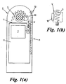
- a handset 1 comprising a speaker unit 10 and an adjacent volume of free space V extending behind the speaker unit (as shown in detail 1(b)) for acoustic enhancement; an antenna arrangement 2 comprising a ground plane 4 and a radiating element 3 extending from a radio frequency feed point 8 on the handsets printed circuit board (PCB) 11.
- PCB printed circuit board
- the radiating element 3 is curved with respect to the ground plane 4 and is arranged to fit around the peripheral edges of the acoustic enhancing volume of free space V, thereby incorporating the volume V within the antenna arrangement 2..
- the ground plane may be formed on the handset's PCB 11, or a metallic plane may be formed perpendicular to the PCB 11 for example by a shielding case.
- the radiating element 3 does not require tuning or matching stubs, nor grounding at any point along its length to achieve the desired resonant frequency from its compact dimensions.
- the radiating element is fed at one end while the other end is left free. This facilitates inclusion of handset elements such as speaker acoustic enhancing volumes between the radiating element 3 and the ground plane 4.
- the antenna arrangement 2 comprises a radiating element 3 and ground plane 4 connected to the handset's radio frequency transceiver circuitry 7 via a radio frequency feed point 8.
- the antenna 2 is shown in plan in figure 2a and in elevation in figure 2b.
- the radiating element 3 is a monopole structure which extends from the feed point 8 in a series of opposing bends which form a zigzag pattern of substantially parallel sections 6 separated by the bends 5.
- the radiating element 3 extends in a curve A with respect to the ground plane 4.
- the series of bends 5 and sections 6 which form the radiating element 3 need not form a regular pattern as is shown in the preferred embodiment.
- a further embodiment antenna 2 is shown in figures 4 (a) and (b) which comprises a dual band antenna 2 in which a plate or planar element 20 is connected to the free end of the radiating element 3 extending back from the connection and substantially parallel with the radiating element 3.
- the presence of the planar element 20 shifts the second harmonic of the fundamental resonant frequency of the antenna 2 along the frequency spectrum effectively introducing a further controllable frequency band.
- the planar element 20 shifts the second harmonic down the frequency spectrum depending on for example the planar elements length and distance from the radiating element 3.
- the dimensions of the planar element 20 and its physical relationship to the radiating element 3 are obtained experimentally for the desired frequency bands.
- Figure 4 shows the dual band antenna tuned to the 850 MHz and 1920 MHz frequency bands.
- the first preferred embodiment antenna arrangement has been shown to have an antenna efficiency of 75% at 850 MHz.
- the antenna efficiency at 850 MHz has been measured at 75%, and at the higher band of 1920 MHz an antenna efficiency of 91% has been achieved. This compares favourably with an antenna efficiency of 71% for a helix antenna at 920 MHz.
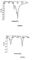
- Figure 5 shows the insertion loss of the single frequency antenna. It can be seen that adequate return loss (>10dB) is seen across the band, this can be improved by retuning. Placement of the intended speaker unit 10 inside the antenna 2 produced only a slight change in frequency which is readily retuned.
- Figures 6, 7 and 8 show respectively the insertion loss of the dual band antenna; the azimuth radiation pattern of the single band antenna; the azimuth radiation pattern of the dual band antenna at 850 MHz; and at 1920 MHz.
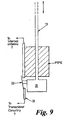
- FIG. 9 a further inventive aspect in which a switching arrangement is used to switch between the internal antenna 2 and an external antenna 13 such as a telescopically extendible monopole.
- an external antenna 13 such as a telescopically extendible monopole.
- the switching arrangement is shown in more detail in figure 9 and makes use of the manual engagement or disengagement of the external antenna 13.
- a metallic contact 31 attached at its base engages a flat spring contact 32 which disconnects the internal antenna 2 from the transceiver output 33, and simultaneously connects the external antenna 13 to the transceiver output 33.
- the reverse occurs when the external antenna 13 is manually pushed back into the handset.
- the switching arrangement could also be modified to operate using external antennas which are folded out or which are physically connected to the handset when required.
- Various alternative switching arrangements are conceivable by a person skilled in the art, including electronic switching, capacitive coupling, and other mechanical switching means.
Description
- The invention generally relates to radio communications handsets, and in particular to internal antenna arrangements.
- Recent advances in mobile communications have been coupled with increasing demand for miniaturisation of mobile communications handsets. A significant limitation on such miniaturisation is the internal antenna size which cannot easily be reduced.
- Existing antennas used in radio communications handsets include extendible monopoles, microstrip patch antennas, inverted L and F antennas, and helix antennas.
- Half or quarter wavelength monopoles extend a significant length from the handset and have a number of disadvantages including the inconvenience of such a long protuberance which is easily broken and can be hazardous to users eyes for example.
- The microstrip patch , while having a low profile, small size and light weight, has low efficiency or a narrow bandwidth.
- The inverted L antenna requires a significant physical length (quarter wavelength) for efficient operation, this is generally not possible within a handset so that a shortened L is generally inefficient. This can be improved by using a tuning element in the form of a stub to the ground plane giving the antenna an inverted F configuration, however this still suffers from inefficiency and limited bandwidth in the physical size constraints applicable to a handset.
- The helix antenna, while conveniently short, still requires a significant cylindrical volume which may be extended outside the main body of the handset forming a short protuberance. While this facilitates to some extent miniaturisation of the main handset, the protuberance is inconvenient in practical use. The helix also suffers from a narrow bandwidth.
- Various meandering antenna arrangements are also known. US4021810 discloses a 3D array of meander structure conductors above a ground plane which is complex to produce and is susceptible to the vagaries of manufacturing tolerances. WO96/38882 discloses a printed meandering monopole antenna extending from a mobile handset. While the meandering monopole is shorter than a standard monopole, it still represents an inconvenient protuberance outside the handset. WO93/12559 discloses a planar metallic sheet inverted F antenna having dependant elements angled with respect to the planar structure. As such it is delicate and complicated to manufacture.
- In addition to the above mentioned antenna size and volume constraints on the miniaturisation of handsets, there is now an increasing need for a handset to be used in different communications systems such as mobile and cordless telephony or mobiles in different countries, which requires the handset to be operable over more than one frequency band. While a single antenna and a multiple band matching circuit may be employed, this can prove overly complex and costly so that in practice each handset may require a separate antenna for each frequency band together with sufficient spacing between adjacent antennas to minimise coupling effects there between.
- US-A-4 679 233 discloses a radio communications handset comprising a speaker having an adjacent volume of free space for acoustic enhancement and an antenna arrangement which incorporates said volume within the antenna arrangement, said antenna arrangement comprising a ground plane and a radiating element. The ground plane has a "u"-shaped form that encloses the free space volume. The radiating element is positioned above the ground plane remote from the free space volume location.
- It is an object of the present invention to facilitate handset miniaturisation by providing improved or alternative internal antenna arrangements for such handsets.
- In accordance with a first aspect, there is provided a radio communications handset comprising:
- a speaker having an adjacent volume of free space V for acoustic enhancement;
- and an antenna arrangement which incorporates said volume within the antenna arrangement, said antenna arrangement comprising a ground plane and a radiating element, characterised in that the arrangement is such that the volume of free space adjacent the speaker is located between the ground plane and the radiating element.
-
- Preferably, the radiating element is spaced a non-uniform distance over its length from said ground plane.
- Preferably, the radiating element of the antenna arrangement comprises a meandering radiating element extending in a series of opposing bends from a radio-frequency feed point.
- Preferably also, said opposing bends in the radiating element are effected in more than one plane.
- Preferably further, the antenna arrangement further comprises a planar element connected to a free end of said radiating element and extending backwards of and substantially parallel with said radiating element
- Preferably further, the radiating element is a monopole antenna radiating element.
- Preferably further, the handset further comprises:
- an extendible external antenna;
- radio frequency transceiver means; and antenna switching means which is arranged to switch between said transceiver means and said external antenna or said antenna arrangement upon manual extension or retraction of said external antenna.
-
- Preferably further, said non-uniform spacing is such that the radiating element extends in an arc across the ground plane.
- In order that a greater understanding of the invention be obtained, embodiments of the invention will now be described with reference to the accompanying drawings, by way of example only and without intending to be limited, in which:
- Figure 1(a) shows a preferred embodiment handset arrangement of the invention, and figure 1(b) shows a detail section of the handset's acoustic volume contained within the handset's antenna arrangement;
- Figures 2 (a) and (b) show in detail an preferred embodiment antenna arrangement of the invention in plan and elevation respectively;
- Figures 3 (a) and (b) show an alternative embodiment antenna arrangement in perspective and section respectively;
- Figures 4 (a) and (b) show a multi band embodiment of the antenna arrangement in plan and elevation respectively;
- Figure 5 shows insertion loss for a single band antenna;
- Figure 6 shows insertion loss for a dual band antenna;
- Figure 7 shows the azimuth radiation pattern for the single band antenna;
- Figure 8 shows the azimuth radiation pattern for the dual band antenna; and
- Figure 9 shows an external antenna switching arrangement.
-
- Referring to figure 1(a), a handset 1 is there shown comprising a
speaker unit 10 and an adjacent volume of free space V extending behind the speaker unit (as shown in detail 1(b)) for acoustic enhancement; anantenna arrangement 2 comprising aground plane 4 and aradiating element 3 extending from a radiofrequency feed point 8 on the handsets printed circuit board (PCB) 11. - The radiating
element 3 is curved with respect to theground plane 4 and is arranged to fit around the peripheral edges of the acoustic enhancing volume of free space V, thereby incorporating the volume V within theantenna arrangement 2.. - The ground plane may be formed on the handset's
PCB 11, or a metallic plane may be formed perpendicular to thePCB 11 for example by a shielding case. - The
radiating element 3 of theantenna arrangement 2 is preferably a monopole type structure formed into a zig-zag pattern which consists of a series of opposing bends. The zigzag formation of theradiating element 3 maintains a small and convenient volume within the handset 1 while providing a self-resonant antenna 2 as described herein below. This particular antenna construction also provides good antenna efficiency and bandwidth characteristics. - It should be noted that unlike conventional short antennas for handset applications, such as inverted F and folded monopole antennas, the radiating
element 3 does not require tuning or matching stubs, nor grounding at any point along its length to achieve the desired resonant frequency from its compact dimensions. By contrast the radiating element is fed at one end while the other end is left free. This facilitates inclusion of handset elements such as speaker acoustic enhancing volumes between theradiating element 3 and theground plane 4. - The inclusion of the acoustics volume V between the
radiating element 3 and theground plane 4 reduces the combined internal antenna and acoustic volumes on further miniaturisation of handsets with this acoustic volume V. - A preferred antenna arrangement is described in more detail with reference to figures 2 (a) and (b). The
antenna arrangement 2 comprises a radiatingelement 3 andground plane 4 connected to the handset's radiofrequency transceiver circuitry 7 via a radiofrequency feed point 8. Theantenna 2 is shown in plan in figure 2a and in elevation in figure 2b. Referring to figure 2a, the radiatingelement 3 is a monopole structure which extends from thefeed point 8 in a series of opposing bends which form a zigzag pattern of substantially parallel sections 6 separated by thebends 5. Referring to figure 2b, the radiatingelement 3 extends in a curve A with respect to theground plane 4. - Each
bend 5 introduces an inductive element Lbn into theantenna 2 which increases with sharpness (reduced radius r) of thebend 5. Capacitive elements Cbn are introduced between adjacent sections 6 which are dependent on the respective parallel lengths I and distances d between adjacent sections. Further capacitive elements Cgn are introduced between the radiatingelement 3 and theground plane 4, each notional capacitance Cgn being dependent on the distance between theground plane 4 and radiatingelement 3 at that point. - The combination of
bends 5 and sections 6 can be thought of as a matching network composed of a variable inductor and capacitor in parallel, together with a shunt capacitor to ground. By varying the length I and separation distance d of the sections 6 the capacitance Cb can be varied and by varying thebend 5 distance or radius r, the inductance L6 can be varied. Similarly by varying the separation between the radiatingelement 3 andground plane 4 and the radiating element radius R, the shunt capacitance Cg can be varied. - By varying these capacitive and inductive elements experimentally the
antenna 2 can be made self-resonant at a desired frequency. Theantenna 2 of the invention therefore does not require a matching network for tuning. - The bandwidth of the antenna can be broadened by extending the total length of the radiating
element 3. The capacitive elements Cgn also influence the bandwidth of thetuned antenna 2. - The centre frequency of the
antenna 2 is influenced by the capacitive elements Cgn and Cbn and the inductive elements Lbn. In practice these elements are varied experimentally to obtain the desired centre frequency and bandwidth of theantenna 2. The dimensions of the resulting antenna structure can then be mass produced as required. - Preferably the radiating
element 3 consists of a piece of plated wire bent into a series of bends to cause inductance and capacitance along its length. Thewhole radiating element 3 sits above theground plane 4 of aPCB 11 in the handset 1, forming a variable impedance transmission line as the distance between theground plane 4 and radiatingelement 3 varies. - The series of
bends 5 and sections 6 which form theradiating element 3 need not form a regular pattern as is shown in the preferred embodiment. - The zig-zag pattern of the
bends 5 and sections 6 is formed in a plane colinear with the direction of extension of the radiating element - denoted by curve A in figure 2b. While this plane is shown in figures 2a and 2b as perpendicular to thePCB 11 plane, the zig-zag pattern may be formed in any plane colinear with curve A. For example figure 1 shows the radiatingelement 3 formed in a plane parallel with thePCB 11 plane. - As a further alternative the radiating element zigzag pattern may be formed in more than one plane as is shown in figure 3 in which the pattern extends in two perpendicular planes - one parallel and one perpendicular to the
PCB 11 plane. - A
further embodiment antenna 2 is shown in figures 4 (a) and (b) which comprises adual band antenna 2 in which a plate orplanar element 20 is connected to the free end of the radiatingelement 3 extending back from the connection and substantially parallel with the radiatingelement 3. The presence of theplanar element 20 shifts the second harmonic of the fundamental resonant frequency of theantenna 2 along the frequency spectrum effectively introducing a further controllable frequency band. Theplanar element 20 shifts the second harmonic down the frequency spectrum depending on for example the planar elements length and distance from the radiatingelement 3. The dimensions of theplanar element 20 and its physical relationship to theradiating element 3 are obtained experimentally for the desired frequency bands. Figure 4 shows the dual band antenna tuned to the 850 MHz and 1920 MHz frequency bands. - In experimentation, the first preferred embodiment antenna arrangement has been shown to have an antenna efficiency of 75% at 850 MHz. For the second preferred dual band antenna arrangement of figure 4, the antenna efficiency at 850 MHz has been measured at 75%, and at the higher band of 1920 MHz an antenna efficiency of 91% has been achieved. This compares favourably with an antenna efficiency of 71% for a helix antenna at 920 MHz.
- Figure 5 shows the insertion loss of the single frequency antenna. It can be seen that adequate return loss (>10dB) is seen across the band, this can be improved by retuning. Placement of the intended
speaker unit 10 inside theantenna 2 produced only a slight change in frequency which is readily retuned. - Figures 6, 7 and 8 show respectively the insertion loss of the dual band antenna; the azimuth radiation pattern of the single band antenna; the azimuth radiation pattern of the dual band antenna at 850 MHz; and at 1920 MHz.
- Referring now to figures 1 and 9 and a further inventive aspect in which a switching arrangement is used to switch between the
internal antenna 2 and anexternal antenna 13 such as a telescopically extendible monopole. This allows each antenna to be individually optimised without the detrimental influence of the other antenna being in circuit. The need for complex and expensive dual matching circuitry is therefore essentially eliminated. The use of the switching arrangement is not restricted to the particular antenna arrangement of the invention as described above, but could be used with any type of internal and external antenna. - The switching arrangement is shown in more detail in figure 9 and makes use of the manual engagement or disengagement of the
external antenna 13. As theexternal antenna 13 is pulled out ametallic contact 31 attached at its base engages aflat spring contact 32 which disconnects theinternal antenna 2 from thetransceiver output 33, and simultaneously connects theexternal antenna 13 to thetransceiver output 33. The reverse occurs when theexternal antenna 13 is manually pushed back into the handset. - The switching arrangement could also be modified to operate using external antennas which are folded out or which are physically connected to the handset when required. Various alternative switching arrangements are conceivable by a person skilled in the art, including electronic switching, capacitive coupling, and other mechanical switching means.
Claims (8)
- A radio communications handset (1) comprising:a speaker (10) having an adjacent volume of free space V for acoustic enhancement;and an antenna arrangement (2) which incorporates said volume within the antenna arrangement, said antenna arrangement comprising a ground plane (14) and a radiating element (3), characterised in that the arrangement is such that the volume of free space adjacent the speaker is located between the ground plane and the radiating element.
- A radio communications handset according to claim 1, characterised in that the radiating element (3) is spaced a non-uniform distance over its length from said ground plane (4).
- A radio communications handset according to claim 1 or claim 2, characterised in that the radiating element of the antenna arrangement (1) comprises a meandering radiating element (3) extending in a series of opposing bends (5) from a radio-frequency feed point (8).
- A radio communications handset according to claim 3, characterised in that said opposing bends (5) in the radiating element (3) are effected in more than one plane.
- A radio communications handset according to any preceding claim, characterised in that the antenna arrangement (2) further comprises a planar element (20) connected to the free end of said radiating element (3) and extending backwards of and substantially parallel with said radiating element.
- A radio communications handset according to any one of claims 3 to 5, characterised in that the radiating element (3) is a monopole antenna radiating element.
- A radio communications handset according to any preceding claim, characterised in that the handset further comprises:an extendible external antenna (13);radio frequency transceiver means (7); andantenna switching means (31,32) which is arranged to switch between said transceiver means (7) and said external antenna (13) or said antenna arrangement (2) upon manual extension or retraction of said external antenna.
- A radio communications handset according to any one of claims 2 to 7, characterised in that said non-uniform spacing is such that the radiating element extends in an arc across the ground plane.
Applications Claiming Priority (2)
| Application Number | Priority Date | Filing Date | Title |
|---|---|---|---|
| US995602 | 1997-12-22 | ||
| US08/995,602 US6304222B1 (en) | 1997-12-22 | 1997-12-22 | Radio communications handset antenna arrangements |
Publications (3)
| Publication Number | Publication Date |
|---|---|
| EP0924793A2 EP0924793A2 (en) | 1999-06-23 |
| EP0924793A3 EP0924793A3 (en) | 2000-03-29 |
| EP0924793B1 true EP0924793B1 (en) | 2003-03-26 |
Family
ID=25541993
Family Applications (1)
| Application Number | Title | Priority Date | Filing Date |
|---|---|---|---|
| EP98203306A Expired - Lifetime EP0924793B1 (en) | 1997-12-22 | 1998-09-30 | Radio communications handset antenna arrangements |
Country Status (5)
| Country | Link |
|---|---|
| US (1) | US6304222B1 (en) |
| EP (1) | EP0924793B1 (en) |
| CA (1) | CA2251314C (en) |
| DE (1) | DE69812565T2 (en) |
| GB (2) | GB9804104D0 (en) |
Cited By (2)
| Publication number | Priority date | Publication date | Assignee | Title |
|---|---|---|---|---|
| US8207893B2 (en) | 2000-01-19 | 2012-06-26 | Fractus, S.A. | Space-filling miniature antennas |
| US8738103B2 (en) | 2006-07-18 | 2014-05-27 | Fractus, S.A. | Multiple-body-configuration multimedia and smartphone multifunction wireless devices |
Families Citing this family (27)
| Publication number | Priority date | Publication date | Assignee | Title |
|---|---|---|---|---|
| DK174546B1 (en) * | 1998-12-21 | 2003-05-19 | Sony Ericsson Mobile Comm Ab | A communication device |
| WO2001009976A1 (en) * | 1999-07-29 | 2001-02-08 | Siemens Aktiengesellschaft | Radio device with a housing having a hollow body for receiving an antenna element |
| EP1526604A1 (en) | 1999-09-20 | 2005-04-27 | Fractus, S.A. | Multilevel antenna |
| FR2802045B1 (en) * | 1999-12-07 | 2002-02-15 | Sagem | CELLULAR NETWORK COMPACT TELEPHONE |
| FR2802709B1 (en) * | 1999-12-15 | 2005-08-05 | Canon Europa Nv | DEVICE FOR ARRANGING A WIRED ANTENNA IN A COMMUNICATION APPARATUS |
| FI114592B (en) * | 2000-06-30 | 2004-11-15 | Nokia Corp | Coupler and adapter arrangements for connecting external and internal antennas for example to an expansion board |
| FI115341B (en) | 2000-08-29 | 2005-04-15 | Nokia Corp | Mobile station and antenna arrangement for a mobile station |
| DE10052909A1 (en) * | 2000-10-25 | 2002-05-08 | Siemens Ag | communication terminal |
| DE10063242C2 (en) | 2000-12-19 | 2003-02-20 | Siemens Ag | Communication terminal with antenna |
| FR2824216B1 (en) * | 2001-04-30 | 2003-08-08 | Sagem | CELLULAR RADIOTELEPHONY TERMINAL WITH INTEGRATED TWO-BAND ANTENNA AND CORRESPONDING ANTENNA |
| FI117233B (en) * | 2001-06-06 | 2006-07-31 | Flextronics Odm Luxembourg Sa | A method for improving the acoustic performance of a terminal and a terminal |
| US6906667B1 (en) * | 2002-02-14 | 2005-06-14 | Ethertronics, Inc. | Multi frequency magnetic dipole antenna structures for very low-profile antenna applications |
| US20030003970A1 (en) * | 2001-06-28 | 2003-01-02 | Alan Johnson | Portable communications device |
| FR2829651B1 (en) * | 2001-09-13 | 2005-06-24 | Cit Alcatel | COMPONENT FOR RADIOCOMMUNICATION TERMINAL COMPRISING ANTENNA, SPEAKER AND RINGER |
| EP1317116B1 (en) * | 2001-11-30 | 2005-05-18 | Sagem SA | Mobile telephone with an integrated element in the space between the antenna and the circuit board |
| US6717551B1 (en) | 2002-11-12 | 2004-04-06 | Ethertronics, Inc. | Low-profile, multi-frequency, multi-band, magnetic dipole antenna |
| US6943730B2 (en) | 2002-04-25 | 2005-09-13 | Ethertronics Inc. | Low-profile, multi-frequency, multi-band, capacitively loaded magnetic dipole antenna |
| US6744410B2 (en) * | 2002-05-31 | 2004-06-01 | Ethertronics, Inc. | Multi-band, low-profile, capacitively loaded antennas with integrated filters |
| US7084813B2 (en) * | 2002-12-17 | 2006-08-01 | Ethertronics, Inc. | Antennas with reduced space and improved performance |
| US6919857B2 (en) * | 2003-01-27 | 2005-07-19 | Ethertronics, Inc. | Differential mode capacitively loaded magnetic dipole antenna |
| US7123209B1 (en) * | 2003-02-26 | 2006-10-17 | Ethertronics, Inc. | Low-profile, multi-frequency, differential antenna structures |
| DE10357176A1 (en) * | 2003-12-06 | 2005-06-30 | Modine Manufacturing Co., Racine | capacitor |
| US7193565B2 (en) * | 2004-06-05 | 2007-03-20 | Skycross, Inc. | Meanderline coupled quadband antenna for wireless handsets |
| US7113135B2 (en) * | 2004-06-08 | 2006-09-26 | Skycross, Inc. | Tri-band antenna for digital multimedia broadcast (DMB) applications |
| US7428431B2 (en) * | 2005-07-06 | 2008-09-23 | Kyocera Wireless Corp. | Extendable antenna and speaker box |
| WO2008119699A1 (en) | 2007-03-30 | 2008-10-09 | Fractus, S.A. | Wireless device including a multiband antenna system |
| US11862838B2 (en) | 2020-04-17 | 2024-01-02 | Apple Inc. | Electronic devices having wideband antennas |
Family Cites Families (18)
| Publication number | Priority date | Publication date | Assignee | Title |
|---|---|---|---|---|
| FI379774A (en) | 1974-12-31 | 1976-07-01 | Martti Eelis Tiuri | |
| US4679233A (en) * | 1985-08-30 | 1987-07-07 | Motorola, Inc. | Microphone |
| US4860020A (en) | 1987-04-30 | 1989-08-22 | The Aerospace Corporation | Compact, wideband antenna system |
| JPH01317001A (en) * | 1988-06-17 | 1989-12-21 | Mitsubishi Electric Corp | Antenna changeover device |
| US4876709A (en) * | 1988-09-08 | 1989-10-24 | Dynascan Corporation | Antenna for cordless telephone system |
| AT396532B (en) | 1991-12-11 | 1993-10-25 | Siemens Ag Oesterreich | ANTENNA ARRANGEMENT, ESPECIALLY FOR COMMUNICATION TERMINALS |
| KR0150247B1 (en) * | 1993-02-25 | 1998-11-02 | 안쏘니 제이. 살리, 주니어 | Receiver having concealed external antenna |
| FR2703550B1 (en) * | 1993-03-30 | 1995-05-24 | Sagem | Portable radio with amplified listening. |
| DE69529192D1 (en) * | 1994-03-08 | 2003-01-30 | Telit Mobile Terminals Spa | PORTABLE TRANSMITTER AND / OR RECEIVER |
| WO1996027219A1 (en) | 1995-02-27 | 1996-09-06 | The Chinese University Of Hong Kong | Meandering inverted-f antenna |
| DE69617947T2 (en) | 1995-06-02 | 2002-06-20 | Ericsson Inc | PRINTED MULTI-BAND MONOPOLAN ANTENNA |
| GB2303968B (en) * | 1995-08-03 | 1999-11-10 | Nokia Mobile Phones Ltd | Antenna |
| US5696517A (en) * | 1995-09-28 | 1997-12-09 | Murata Manufacturing Co., Ltd. | Surface mounting antenna and communication apparatus using the same |
| JP3166589B2 (en) | 1995-12-06 | 2001-05-14 | 株式会社村田製作所 | Chip antenna |
| EP0790668B1 (en) * | 1996-02-19 | 2003-06-18 | Murata Manufacturing Co., Ltd. | Antenna apparatus and communication apparatus using the same |
| EP0806810A3 (en) * | 1996-05-07 | 1998-04-08 | Ascom Tech Ag | Antenna formed of a strip-like resonance element over a base plate |
| GB9627091D0 (en) * | 1996-12-31 | 1997-02-19 | Northern Telecom Ltd | An inverted E antenna |
| FI112723B (en) * | 1997-03-27 | 2003-12-31 | Nokia Corp | Antenna for wireless telephones |
-
1997
- 1997-12-22 US US08/995,602 patent/US6304222B1/en not_active Expired - Lifetime
-
1998
- 1998-02-27 GB GBGB9804104.9A patent/GB9804104D0/en not_active Ceased
- 1998-02-27 GB GBGB9804103.1A patent/GB9804103D0/en not_active Ceased
- 1998-09-30 EP EP98203306A patent/EP0924793B1/en not_active Expired - Lifetime
- 1998-09-30 DE DE69812565T patent/DE69812565T2/en not_active Expired - Lifetime
- 1998-10-23 CA CA002251314A patent/CA2251314C/en not_active Expired - Lifetime
Cited By (8)
| Publication number | Priority date | Publication date | Assignee | Title |
|---|---|---|---|---|
| US8207893B2 (en) | 2000-01-19 | 2012-06-26 | Fractus, S.A. | Space-filling miniature antennas |
| US8212726B2 (en) | 2000-01-19 | 2012-07-03 | Fractus, Sa | Space-filling miniature antennas |
| US8471772B2 (en) | 2000-01-19 | 2013-06-25 | Fractus, S.A. | Space-filling miniature antennas |
| US8558741B2 (en) | 2000-01-19 | 2013-10-15 | Fractus, S.A. | Space-filling miniature antennas |
| US8610627B2 (en) | 2000-01-19 | 2013-12-17 | Fractus, S.A. | Space-filling miniature antennas |
| US9331382B2 (en) | 2000-01-19 | 2016-05-03 | Fractus, S.A. | Space-filling miniature antennas |
| US8738103B2 (en) | 2006-07-18 | 2014-05-27 | Fractus, S.A. | Multiple-body-configuration multimedia and smartphone multifunction wireless devices |
| US9099773B2 (en) | 2006-07-18 | 2015-08-04 | Fractus, S.A. | Multiple-body-configuration multimedia and smartphone multifunction wireless devices |
Also Published As
| Publication number | Publication date |
|---|---|
| EP0924793A3 (en) | 2000-03-29 |
| GB9804104D0 (en) | 1998-04-22 |
| GB9804103D0 (en) | 1998-04-22 |
| EP0924793A2 (en) | 1999-06-23 |
| CA2251314C (en) | 2007-03-13 |
| DE69812565D1 (en) | 2003-04-30 |
| US6304222B1 (en) | 2001-10-16 |
| CA2251314A1 (en) | 1999-06-22 |
| DE69812565T2 (en) | 2003-09-25 |
Similar Documents
| Publication | Publication Date | Title |
|---|---|---|
| EP0924793B1 (en) | Radio communications handset antenna arrangements | |
| KR100723086B1 (en) | Asymmetric dipole antenna assembly | |
| US7148847B2 (en) | Small-size, low-height antenna device capable of easily ensuring predetermined bandwidth | |
| US4571595A (en) | Dual band transceiver antenna | |
| US7755545B2 (en) | Antenna and method of manufacturing the same, and portable wireless terminal using the same | |
| US6204826B1 (en) | Flat dual frequency band antennas for wireless communicators | |
| EP0655797B1 (en) | Quarter-wave gap-coupled tunable strip antenna | |
| US6218992B1 (en) | Compact, broadband inverted-F antennas with conductive elements and wireless communicators incorporating same | |
| US6100848A (en) | Multiple band printed monopole antenna | |
| EP1202382B1 (en) | Antenna | |
| US6025805A (en) | Inverted-E antenna | |
| EP1204159A2 (en) | Antenna equipment | |
| US6229487B1 (en) | Inverted-F antennas having non-linear conductive elements and wireless communicators incorporating the same | |
| EP1057223A1 (en) | Dual band antenna for radio terminal | |
| WO1996038882A9 (en) | Multiple band printed monopole antenna | |
| CN102165641A (en) | Antenna combination | |
| JP2002009539A (en) | Integrated antenna for mobile phone | |
| KR100766784B1 (en) | Antenna | |
| US6567047B2 (en) | Multi-band in-series antenna assembly | |
| KR20020015694A (en) | Flat-plate monopole antennae | |
| EP2047561A2 (en) | Antenna arrangement | |
| EP0470797A2 (en) | Antenna apparatus | |
| KR200284259Y1 (en) | A portable phone antenna having the zig-zag shaped line | |
| KR100688648B1 (en) | Multi-band internal antenna using a short stub for mobile terminals | |
| KR100896441B1 (en) | Broad Band Antenna |
Legal Events
| Date | Code | Title | Description |
|---|---|---|---|
| PUAI | Public reference made under article 153(3) epc to a published international application that has entered the european phase |
Free format text: ORIGINAL CODE: 0009012 |
|
| AK | Designated contracting states |
Kind code of ref document: A2 Designated state(s): DE FI FR GB IT SE |
|
| AX | Request for extension of the european patent |
Free format text: AL;LT;LV;MK;RO;SI |
|
| RAP3 | Party data changed (applicant data changed or rights of an application transferred) |
Owner name: NORTEL NETWORKS CORPORATION |
|
| PUAL | Search report despatched |
Free format text: ORIGINAL CODE: 0009013 |
|
| AK | Designated contracting states |
Kind code of ref document: A3 Designated state(s): AT BE CH CY DE DK ES FI FR GB GR IE IT LI LU MC NL PT SE |
|
| AX | Request for extension of the european patent |
Free format text: AL;LT;LV;MK;RO;SI |
|
| RAP1 | Party data changed (applicant data changed or rights of an application transferred) |
Owner name: NORTEL NETWORKS LIMITED |
|
| 17P | Request for examination filed |
Effective date: 20000929 |
|
| AKX | Designation fees paid |
Free format text: DE FI FR GB IT SE |
|
| 17Q | First examination report despatched |
Effective date: 20020423 |
|
| GRAH | Despatch of communication of intention to grant a patent |
Free format text: ORIGINAL CODE: EPIDOS IGRA |
|
| GRAH | Despatch of communication of intention to grant a patent |
Free format text: ORIGINAL CODE: EPIDOS IGRA |
|
| GRAA | (expected) grant |
Free format text: ORIGINAL CODE: 0009210 |
|
| AK | Designated contracting states |
Designated state(s): DE FI FR GB IT SE |
|
| PG25 | Lapsed in a contracting state [announced via postgrant information from national office to epo] |
Ref country code: IT Free format text: LAPSE BECAUSE OF FAILURE TO SUBMIT A TRANSLATION OF THE DESCRIPTION OR TO PAY THE FEE WITHIN THE PRESCRIBED TIME-LIMIT;WARNING: LAPSES OF ITALIAN PATENTS WITH EFFECTIVE DATE BEFORE 2007 MAY HAVE OCCURRED AT ANY TIME BEFORE 2007. THE CORRECT EFFECTIVE DATE MAY BE DIFFERENT FROM THE ONE RECORDED. Effective date: 20030326 Ref country code: FI Free format text: LAPSE BECAUSE OF FAILURE TO SUBMIT A TRANSLATION OF THE DESCRIPTION OR TO PAY THE FEE WITHIN THE PRESCRIBED TIME-LIMIT Effective date: 20030326 |
|
| REG | Reference to a national code |
Ref country code: GB Ref legal event code: FG4D |
|
| REF | Corresponds to: |
Ref document number: 69812565 Country of ref document: DE Date of ref document: 20030430 Kind code of ref document: P |
|
| PG25 | Lapsed in a contracting state [announced via postgrant information from national office to epo] |
Ref country code: SE Free format text: LAPSE BECAUSE OF FAILURE TO SUBMIT A TRANSLATION OF THE DESCRIPTION OR TO PAY THE FEE WITHIN THE PRESCRIBED TIME-LIMIT Effective date: 20030626 |
|
| RAP2 | Party data changed (patent owner data changed or rights of a patent transferred) |
Owner name: NORTEL NETWORKS LIMITED |
|
| ET | Fr: translation filed | ||
| PLBE | No opposition filed within time limit |
Free format text: ORIGINAL CODE: 0009261 |
|
| STAA | Information on the status of an ep patent application or granted ep patent |
Free format text: STATUS: NO OPPOSITION FILED WITHIN TIME LIMIT |
|
| 26N | No opposition filed |
Effective date: 20031230 |
|
| REG | Reference to a national code |
Ref country code: GB Ref legal event code: 732E Free format text: REGISTERED BETWEEN 20130502 AND 20130508 |
|
| REG | Reference to a national code |
Ref country code: GB Ref legal event code: 732E Free format text: REGISTERED BETWEEN 20130509 AND 20130515 |
|
| REG | Reference to a national code |
Ref country code: FR Ref legal event code: TP Owner name: APPLE INC., US Effective date: 20130515 |
|
| REG | Reference to a national code |
Ref country code: DE Ref legal event code: R082 Ref document number: 69812565 Country of ref document: DE Representative=s name: BARDEHLE PAGENBERG PARTNERSCHAFT MBB PATENTANW, DE Effective date: 20130801 Ref country code: DE Ref legal event code: R082 Ref document number: 69812565 Country of ref document: DE Representative=s name: BARDEHLE PAGENBERG PARTNERSCHAFT MBB PATENTANW, DE Effective date: 20140313 Ref country code: DE Ref legal event code: R081 Ref document number: 69812565 Country of ref document: DE Owner name: APPLE INC., CUPERTINO, US Free format text: FORMER OWNER: NORTEL NETWORKS LTD., ST. LAURENT, QUEBEC, CA Effective date: 20140313 Ref country code: DE Ref legal event code: R081 Ref document number: 69812565 Country of ref document: DE Owner name: APPLE INC., US Free format text: FORMER OWNER: NORTEL NETWORKS LTD., ST. LAURENT, CA Effective date: 20140313 |
|
| REG | Reference to a national code |
Ref country code: FR Ref legal event code: PLFP Year of fee payment: 19 |
|
| REG | Reference to a national code |
Ref country code: FR Ref legal event code: PLFP Year of fee payment: 20 |
|
| PGFP | Annual fee paid to national office [announced via postgrant information from national office to epo] |
Ref country code: GB Payment date: 20170927 Year of fee payment: 20 Ref country code: FR Payment date: 20170810 Year of fee payment: 20 |
|
| PGFP | Annual fee paid to national office [announced via postgrant information from national office to epo] |
Ref country code: DE Payment date: 20170927 Year of fee payment: 20 |
|
| REG | Reference to a national code |
Ref country code: DE Ref legal event code: R071 Ref document number: 69812565 Country of ref document: DE |
|
| REG | Reference to a national code |
Ref country code: GB Ref legal event code: PE20 Expiry date: 20180929 |
|
| PG25 | Lapsed in a contracting state [announced via postgrant information from national office to epo] |
Ref country code: GB Free format text: LAPSE BECAUSE OF EXPIRATION OF PROTECTION Effective date: 20180929 |